1
PV Inverter
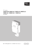
SUNNY BOY US
User Manual
SB_CL_US-BUS094410 | TBUS-SBUS | Version 1.0
US
SMA America, LLC
Legal Restrictions
Copyright © 2010 SMA America, LLC. All rights reserved.
No part of this document may be reproduced, stored in a retrieval system, or transmitted, in any form
or by any means, electronic, mechanical, photographic, magnetic or otherwise, without the prior
written permission of SMA America, LLC.
SMA America, LLC makes no representations, express or implied, with respect to this documentation
or any of the equipment and/or software it may describe, including (with no limitation) any implied
warranties of utility, merchantability, or fitness for any particular purpose. All such warranties are
expressly disclaimed. Neither SMA America, LLC nor its distributors or dealers shall be liable for any
indirect, incidental, or consequential damages under any circumstances.
(The exclusion of implied warranties may not apply in all cases under some statutes, and thus the
above exclusion may not apply.)
Specifications are subject to change without notice. Every attempt has been made to make this
document complete, accurate and up-to-date. Readers are cautioned, however, that
SMA America, LLC reserves the right to make changes without notice and shall not be responsible for
any damages, including indirect, incidental or consequential damages, caused by reliance on the
material presented, including, but not limited to, omissions, typographical errors, arithmetical errors
or listing errors in the content material.
All trademarks are recognized even if these are not marked separately. Missing designations do not
mean that a product or brand is not a registered trademark.
The Bluetooth® word mark and logos are registered trademarks owned by Bluetooth SIG, Inc. and
any use of such marks by SMA America, LLC is under license.
SMA America, LLC
3801 N. Havana Street
Denver, CO 80239 U.S.A.
User Manual
SB_CL_US-BUS094401
3
Important Safety Instructions
SMA America, LLC
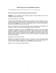
IMPORTANT SAFETY INSTRUCTIONS
SAVE THESE INSTRUCTIONS
This manual contains important instructions for Sunny Boy inverter, that must be followed during
installation and maintenance of the inverter.
The Sunny Boy is designed and tested according to international safety requirements, but as with all
electrical and electronic equipment, certain precautions must be observed when installing and/or
operating the Sunny Boy. To reduce the risk of personal injury and to ensure the safe installation and
operation of the Sunny Boy, you must carefully read and follow all instructions, cautions and warnings
in this user manual.
Warnings in this document
A warning describes a hazard to equipment or personnel. It calls attention to a procedure or practice,
which, if not correctly performed or adhered to, could result in damage to or destruction of part or all
of the SMA equipment and/or other equipment connected to the SMA equipment or personal injury.
DANGER
DANGER indicates a hazardous situation which, if not avoided, will result in death or
serious injury.
WARNING
WARNING indicates a hazardous situation which, if not avoided, could result in death or
serious injury.
CAUTION
CAUTION indicates a hazardous situation which, if not avoided, could result in minor or
moderate injury.
NOTICE
NOTICE is used to address practices not related to personal injury.
4
SB_CL_US-BUS094401
User Manual
SMA America, LLC
Important Safety Instructions
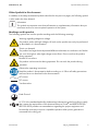
Other Symbols in this document
In addition to the safety and hazard symbols described on the previous pages, the following symbol
is also used in this User Manual:
Information
This symbol accompanies notes that call attention to supplementary information that you
must know and use to ensure optimal operation of the system.
Markings on this product
The following symbols are used as product markings with the following meanings.
Warning regarding dangerous voltage
The product works with high voltages. All work on the product must only be performed
as described in it‘s documentation.
Electric arc hazards
The product has large electrical potential differences between its conductors. Arc flashes
can occur through air when high-voltage current flows. Do not work on the product
during operation.
Beware of hot surface
The product can become hot during operation. Do not touch the product during
operation.
Observe the operating instructions
Read the product’s documentation before working on it. Follow all safety precautions
and instructions as described in the documentation.
AC current
DC current
Transformerless
Earth Ground
UL1741 is the standard applied by Underwriters Laboratories to the Sunny Boy to certify
that it meets the requirements of the National Electrical Code® and IEEE-929-2000.
IEEE 929-2000 provides recommendations regarding the proper equipment and
functionality necessary to ensure compatible operation when power generation is
connected to the utility grid.
User Manual
SB_CL_US-BUS094401
5
General Warnings
SMA America, LLC
General Warnings
General Warnings
All electrical installations must be done in accordance with the local and National
Electrical Code® ANSI/NFPA 70. For installation in Canada the installations must be done
in accordance with applicable Canadian standards.
The Sunny Boy contains no user-serviceable parts except for the fans on the bottom of the
enclosure and the filters behind the fans as well as the handle covers on the sides of the
unit. For all repair and maintenance, always return the unit to an authorized SMA Service
Center.
Before installing or using the Sunny Boy, read all of the instructions, cautions, and warnings
on the Sunny Boy in this User Manual.
Before connecting the Sunny Boy to the electrical utility grid, contact the local utility
company. This connection must be made only by qualified personnel.
Wiring of the Sunny Boy must be made by qualified personnel only.
6
SB_CL_US-BUS094401
User Manual
SMA America, LLC
Table of Contents
Table of Contents
1
1.1
1.2
1.3
1.4
1.5
Notes on this manual. . . . . . . . . . . . . . . . . . . . . . . . . . . . . .
Validity . . . . . . . . . . . . . . . . . . . . . . . . . . . . . . . . . . . . . . . . . . . .
Target group . . . . . . . . . . . . . . . . . . . . . . . . . . . . . . . . . . . . . . . .
Storage of the manuals. . . . . . . . . . . . . . . . . . . . . . . . . . . . . . . .
Additional information . . . . . . . . . . . . . . . . . . . . . . . . . . . . . . . .
Nomenclature . . . . . . . . . . . . . . . . . . . . . . . . . . . . . . . . . . . . . . .
9
9
9
9
9
9
2
2.1
2.2
2.3
Safety . . . . . . . . . . . . . . . . . . . . . . . . . . . . . . . . . . . . . . . . . 10
Appropriate usage . . . . . . . . . . . . . . . . . . . . . . . . . . . . . . . . . . 10
Safety precautions . . . . . . . . . . . . . . . . . . . . . . . . . . . . . . . . . . 11
Identifying the Sunny Boy . . . . . . . . . . . . . . . . . . . . . . . . . . . . . 12
3
3.1
Operating modes . . . . . . . . . . . . . . . . . . . . . . . . . . . . . . . . 13
LED operation indicators. . . . . . . . . . . . . . . . . . . . . . . . . . . . . . 14
3.1.1
All LEDs are off . . . . . . . . . . . . . . . . . . . . . . . . . . . . . . . . . . . . . . . . . . . . . . . 14
3.1.2
All LEDs are on . . . . . . . . . . . . . . . . . . . . . . . . . . . . . . . . . . . . . . . . . . . . . . . 14
3.1.3
The green LED is blinking rapidly . . . . . . . . . . . . . . . . . . . . . . . . . . . . . . . . . 14
3.1.4
The green LED is blinking slowly . . . . . . . . . . . . . . . . . . . . . . . . . . . . . . . . . 15
3.1.5
The green LED is continuously on . . . . . . . . . . . . . . . . . . . . . . . . . . . . . . . . . 15
3.1.6
The green LED goes out briefly . . . . . . . . . . . . . . . . . . . . . . . . . . . . . . . . . . . 15
3.2
LED fault indicators . . . . . . . . . . . . . . . . . . . . . . . . . . . . . . . . . . 16
3.2.1
Red and Yellow LEDs are on. . . . . . . . . . . . . . . . . . . . . . . . . . . . . . . . . . . . . 16
3.2.2
3.2.3
The Red LED is continously on. . . . . . . . . . . . . . . . . . . . . . . . . . . . . . . . . . . . 16
The yellow LED blinks twice. . . . . . . . . . . . . . . . . . . . . . . . . . . . . . . . . . . . . . 17
3.2.4
The yellow LED blinks 4 times . . . . . . . . . . . . . . . . . . . . . . . . . . . . . . . . . . . . 18
3.2.5
The yellow LED blinks 5 times . . . . . . . . . . . . . . . . . . . . . . . . . . . . . . . . . . . . 18
3.2.6
The yellow LED blinks 6 times . . . . . . . . . . . . . . . . . . . . . . . . . . . . . . . . . . . . 19
3.2.7
The yellow LED blinks 7 times . . . . . . . . . . . . . . . . . . . . . . . . . . . . . . . . . . . . 20
4
4.1
Information on the display . . . . . . . . . . . . . . . . . . . . . . . . 21
Activating the backlight. . . . . . . . . . . . . . . . . . . . . . . . . . . . . . . 21
User Manual
SB_CL_US-BUS094401
7
Table of Contents
SMA America, LLC
4.2
4.3
4.4
Display messages in the startup phase . . . . . . . . . . . . . . . . . . . 22
Display messages during operation . . . . . . . . . . . . . . . . . . . . . 22
Fault messages . . . . . . . . . . . . . . . . . . . . . . . . . . . . . . . . . . . . . 22
4.4.1
Disturbance . . . . . . . . . . . . . . . . . . . . . . . . . . . . . . . . . . . . . . . . . . . . . . . . . . 23
4.4.2
Warning . . . . . . . . . . . . . . . . . . . . . . . . . . . . . . . . . . . . . . . . . . . . . . . . . . . . 23
4.4.3
Error . . . . . . . . . . . . . . . . . . . . . . . . . . . . . . . . . . . . . . . . . . . . . . . . . . . . . . . 23
4.4.4
Rapid Blinking of background illumination . . . . . . . . . . . . . . . . . . . . . . . . . . 24
5
5.1
Maintenance and cleaning . . . . . . . . . . . . . . . . . . . . . . . . 25
Checking heat dissipation. . . . . . . . . . . . . . . . . . . . . . . . . . . . . 25
5.1.1
Cleaning the fans . . . . . . . . . . . . . . . . . . . . . . . . . . . . . . . . . . . . . . . . . . . . . 25
5.2
Cleaning the display . . . . . . . . . . . . . . . . . . . . . . . . . . . . . . . . . 25
6
6.1
6.2
6.3
Measurement channels and messages . . . . . . . . . . . . . . 26
Measuring channels . . . . . . . . . . . . . . . . . . . . . . . . . . . . . . . . . 26
Status Messages . . . . . . . . . . . . . . . . . . . . . . . . . . . . . . . . . . . . 27
Error messages . . . . . . . . . . . . . . . . . . . . . . . . . . . . . . . . . . . . . 29
7
Glossary . . . . . . . . . . . . . . . . . . . . . . . . . . . . . . . . . . . . . . . 35
8
Contact . . . . . . . . . . . . . . . . . . . . . . . . . . . . . . . . . . . . . . . . 37
8
SB_CL_US-BUS094401
User Manual
SMA America, LLC
Notes on this manual
1 Notes on this manual
1.1 Validity
This manual describes how to operate the following SMA inverters:
• Sunny Boy 8000TL-US (SB 8000TLUS-10)
• Sunny Boy 9000TL-US (SB 9000TLUS-10)
• Sunny Boy 10000TL-US (SB 10000TLUS-10)
This manual does not cover any details concerning equipment connected to the Sunny Boy (e. g. PV
modules). Information concerning the connected equipment is available from the manufacturer of the
equipment.
1.2 Target group
This manual is for qualified personnel an for the operator.
• Qualified personnel have received training and have demonstrated skills and knowledge in the
construction and operation of this device. Qualified personnel are trained to deal with the
dangers and hazards involved in installing electric devices.
• The operator has been adequately supervised by qualified personnel to ensure a save use of
the Sunny Boy.
1.3 Storage of the manuals
Keep all Sunny Boy manuals in a convenient place for future reference.
1.4 Additional information
You will find further information on special topics in the download area at www.SMA-America.com.
1.5 Nomenclature
In this document SMA America Production, LLC is referred to in the following as SMA.
The syntax specified here for menus and parameters applies throughout the entire manual:
User Manual
SB_CL_US-BUS094410
9
Safety
SMA America, LLC
2 Safety
2.1 Appropriate usage
The Sunny Boy is a PV inverter which converts the DC current of the PV array to AC current and feeds
it into the grid.
More precise information on this subject and on your device can be found in the installation guide.
The operational limits specified in the installation guide for the particular inverter must be observed.
All inverters may only be operated with PV generators (modules and cabling) with protective
insulation. Do not connect any sources of energy other than PV modules to the inverter.
Do not use the inverter for purposes other than those described here. Alternative uses, modifications
to the inverter or the installation of components not expressly recommended or sold by the
manufacturer void the warranty claims and operating permission. If you have questions regarding the
proper usage of the inverters, contact the SMA Serviceline.
Principle of the string inverter
The string inverter is used to connect a number of series-connected PV modules (strings) to the public
supply grid. This way, even a large PV generator can be constructed from a large number of
individual strings, each having its own string inverter. The energy is then combined on the AC side.
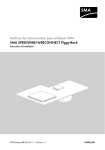
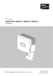
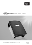
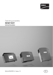
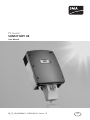
Principle of a PV plant with a Sunny Boy
Position
A
B
C
D
E
F
G
10
Description
PV modules
Sunny Boy Combiner Box
Sunny Boy with SMA DC Disconnect
AC load circuit breaker
Load
Energy meter
Utility grid
SB_CL_US-BUS094410
User Manual
SMA America, LLC
Safety
2.2 Safety precautions
DANGER
During operation, high voltages are present in the Sunny Boy.
Death or serious injury due to electric shock.
The following work on the inverter must be carried out by qualified personnel only.
• Electrical installation
• Repairs
• Modifications
Even when no external voltage is applied, high voltages can still be present in the device.
These high voltages can result in death or serious injury.
WARNING
The Sunny Boy becomes hot during operation.
Risk of burn.
• Do not touch the enclosure during operation.
• Only touch the lid during operation.
NOTICE
Overvoltages in the inverter.
Destruction of the inverter will result.
• Contact your installer whenever the inverter reports an error.
User Manual
SB_CL_US-BUS094410
11
Safety
SMA America, LLC
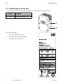
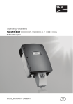
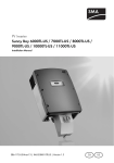
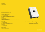
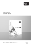
2.3 Identifying the Sunny Boy
You can identify the Sunny Boy by the type label. It is on the right side of the enclosure.
Position
A
B
Description
Type label
General warning label
The type label shows:
• The serial number (Serial No.).
• The type of product (Type/Model).
• Device-specific characteristics.
12
SB_CL_US-BUS094410
User Manual
SMA America, LLC
Operating modes
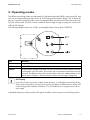
3 Operating modes
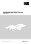
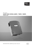
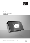
The different operating modes are indicated by 3 light-emitting diodes (LEDs) on the inverter lid, and
also via the integrated display (see section 4 "Information on the display" (page 21)). To allow the
device to signal its operating mode via the 3 integrated LEDs, the inverter must be connected to the
DC side of the system. The level of solar irradiation must be high enough to supply the inverter with
sufficient DC voltage.
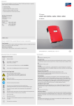
The following diagram shows the 3 LEDs, as exemplified by the Sunny Boy 10000TLUS.
LED
Green
Red
Yellow
Meaning
The green LED indicates normal operation of the inverter.
The red LED indicates an earth fault.
The yellow LED indicates that there is a fault of some kind, either inside the inverter
or somewhere in the PV system. The inverter will not operate until the fault has been
corrected. The different error codes and possible causes are addressed later in this
section and in chapter 6 "Measurement channels and messages" (page 26).
LED Display
If you do not have any means of plant communication, it is advisable, particularly during
the first year of operation, to keep a close eye on this display at different times of day and
under varying solar irradiation conditions. This will enable you to recognize errors at an
early stage.
A detailed description of the possible LED signals and blink codes is given in the following section.
User Manual
SB_CL_US-BUS094410
13
Operating modes
SMA America, LLC
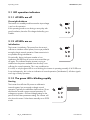
3.1 LED operation indicators
3.1.1 All LEDs are off
Overnight shutdown
The inverter is in standby mode because the input voltage
is too low for operation.
If this operating mode occurs during a sunny day with
good irradiation, have the PV voltage checked by your
installer.
3.1.2 All LEDs are on
Initialization
The inverter is initializing. The power from the array is
sufficient to initialize control power, but not yet powerful
enough to begin normal operation. Data transmission is
not possible during initialization.
Occasionally, during inclement weather or low
irradiation, the LEDs may all turn on at once and then go
off again. This indicates that the inverter is trying to
initialize but the power available from the array is not
sufficient for normal operation. This is not a malfunction.
If no LED, or only the green LED is on or blinking, the inverter is operating normally. If all 3 LEDs are
lit up simultaneously, this is also an indication of normal operation ("initialization"). All other signals
are a sign of faulty operation.
3.1.3 The green LED is blinking rapidly
Starting
The inverter has sufficient PV power to calibrate its
internal systems, but not enough to begin normal
operation. Typically, the calibration lasts less than 10 sec.
and then the inverter resumes normal operation. PV
voltage must remain > PV Start Voltage setting for the
period of the P-Start parameter setting. The inverter will
also show this status if it has been manually set to STOP
mode.
14
SB_CL_US-BUS094410
User Manual
SMA America, LLC
Operating modes
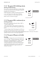
3.1.4 The green LED is blinking slowly
Waiting, Grid Monitoring
The inverter has determined that there is enough voltage
from the array to operate and is checking the condition of
the grid prior to connecting to it.
If the inverter fails to connect to the utility grid 3 times in
a row, it will wait 10 min. before the next attempt.
In case of a grid failure, the Sunny Boy waits 5 min.
before it tries to reconnect to the grid.
3.1.5 The green LED is continuously on
Feeding operation
The inverter is feeding the utility grid in either “MPP” or
“Constant Voltage” mode.
“MPP” Mode: The Sunny Boy adjusts the voltage and
current from the PV array to obtain the greatest PV output
power.
“Constant Voltage” Mode: The voltage from the PV array
has been set to a fixed value. This value is set by using the
Sunny Boy Control or the Sunny Data software (the parameter name is “V-Const”). This mode is
typically used for fuel cell or micro-hydro applications.
3.1.6 The green LED goes out briefly
Derating
The Sunny Boy is designed to operate at full rated power
up to 113 °F (45 °C) ambient temperature. The inverter
will continue to operate beyond 113 °C (45 °C) and
will derate as required to maintain a safe internal
component temperature. Unnecessary derating can be
caused by blocked fan intakes. For this reason the fan
intakes must be inspected in regular intervals and
cleaned if necessary.
User Manual
SB_CL_US-BUS094410
15
Operating modes
SMA America, LLC
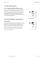
3.2 LED fault indicators
3.2.1 Red and Yellow LEDs are on
The inverter has detected a ground fault in the PV system
and has disconnected from the grid. The ground fault
must be located and fixed before the inverter will resume
normal operation. Refer to the installation guide for
information on solving PV array ground faults (the inverter
will not restart automatically).
3.2.2 The Red LED is continously on
Ground fault
The red LED on the Sunny Boy is permanently on. With
this blink code it is irrelevant whether the green or yellow
LEDs are on or blinking. When the red LED lights up
continuously, the inverter has detected a ground fault.
Contact your installer to have the error corrected.
Instructions on correction errors can be found in the
inverter installation guide.
16
SB_CL_US-BUS094410
User Manual
SMA America, LLC
Operating modes
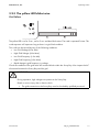
3.2.3 The yellow LED blinks twice
Grid failure
The yellow LED is on for 5 sec., out for 3 sec. and then blinks twice. The code is repeated 3 times. This
code sequence will repeat as long as there is a grid fault condition.
This code can be caused by any of the following conditions:
• Low Grid Voltage (<Vac Min)
• High Grid Voltage (>Vac Max)
• Low Grid Frequency (< fac Min)
• High Grid Frequency (>fac Max)
• Rapid change in grid frequency or voltage
Check the condition of the grid at the AC terminal blocks within the Sunny Boy. Also inspect the AC
disconnect between the Sunny Boy and the grid.
WARNING
During operation, high voltages are present in the Sunny Boy.
Death or serious injury due to electric shock.
• The grid connection to the Sunny Boy must be checked by qualified personnel.
User Manual
SB_CL_US-BUS094410
17
Operating modes
SMA America, LLC
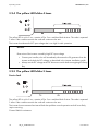
3.2.4 The yellow LED blinks 4 times
The yellow LED is on for 5 sec., remains off for 3 sec. and then blinks 4 times. The code is repeated
3 times. If the condition remains the code will continue to be sent.
The inverter has detected a DC input voltage that is too high for safe operation.
NOTICE
Destruction of the inverter caused by high DC input voltage.
• Contact your installer, who will immediately disconnect the PV generator from the
inverter and check the DC voltage, as described in the inverter installation guide.
• Always test the DC voltage at the DC disconnect switch before energizing the Sunny
Boy.
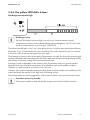
3.2.5 The yellow LED blinks 5 times
Device fault
The yellow LED is on for 5 sec., remains off for 3 sec. and then blinks 5 times. The code is repeated
3 times. If the condition remains the code will continue to be sent.
The inverter has encountered an internal fault that prohibits normal operation and will most likely
require servicing.
Contact SMA for assistance.
18
SB_CL_US-BUS094410
User Manual
SMA America, LLC
Operating modes
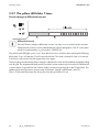
3.2.6 The yellow LED blinks 6 times
Discharge current too high
Discharge current
The fault "Discharge current too high" can only occur in transformerless inverters.
Transformerless inverters can be identified by their device designation. The "TL" in the name
stands for transformerless, e.g. Sunny Boy 10000TL‑US.
The yellow fault LED lights up for 5 sec. when the fault occurs, and then starts emitting the following
blink code. 3 sec. off and then 6 brief consecutive blinks. This code is emitted 3 times in succession.
If this fault is still present, the fault signal starts over again.
The discharge current from the inverter and the PV generator is too high. The Sunny Boy interrupts grid
feeding immediately after exceeding a threshold value and switches back onto the grid automatically
after testing. If necessary, testing will be repeated several times.
Discharge current is dependent on the capacity of the PV generator relative to ground and also
depends on the type of modules and manner of installation as well as the weather conditions.
Therefore, it is quite normal for this value to vary over time.
However, if the inverter frequently displays this fault, please notify the installer who installed your PV
system and clarify the reasons for the high level of discharge current.
This fault message can also be triggered by a PE connection which is not connected to the inverter.
Correction of error by installer
Contact your installer to deal with the fault or get in touch with the SMA Serviceline.
User Manual
SB_CL_US-BUS094410
19
Operating modes
SMA America, LLC
3.2.7 The yellow LED blinks 7 times
Drastic change in differential current
Differential current
The fault "Drastic change in differential current" can only occur in transformerless inverters.
Transformerless inverters can be identified by their device designation. The "TL" in the name
stands for transformerless, e.g. Sunny Boy 10000TL‑US.
The yellow fault LED lights up for 5 sec. when the fault occurs, and then starts emitting the following
blink code. 3 sec. off and then 7 brief consecutive blinks. This code is emitted 3 times in succession.
If this fault is still present, the fault signal starts over again.
The Sunny Boy has detected a drastic change in differential current and immediately stopped feeding
into the grid. The integrated all-pole-sensitive residual current monitoring unit monitors the differential
current relative to ground from the inverter supply connection right through to the PV generator. This
additional personal protection system reacts to a drastic change in differential current of
IDN > 30 mA and disconnects the Sunny Boy from the grid within 0.2 sec.
20
SB_CL_US-BUS094410
User Manual
SMA America, LLC
Information on the display
4 Information on the display
Sunny Boy inverters are equipped with a LC display in the lid.
Display Messages
Detailed explanations of the individual error and fault messages can be found in section
6 "Measurement channels and messages" (page 26).
4.1 Activating the backlight
The backlight is switched on by knocking on the lid. Additional knocks switch the display on to the
next message.
The backlight shuts off automatically after 2 min.
User Manual
SB_CL_US-BUS094410
21
Information on the display
SMA America, LLC
4.2 Display messages in the startup phase
• After startup of the inverter, the display first shows
the device type.
• After 6 sec., the display shows the firmware
versions of the operation control unit (BFR) and the
current control unit (SRR).
4.3 Display messages during operation
The LCD continuously scrolls through all relevant operating data. Each message is displayed for 5
sec., after all messages have been displayed the LCD repeats from the beginning.
• Message 1: Energy generated that day and the
current operating mode:
• Message 2: Nominal grid voltage configuration
and actual line-to-neutral voltage measurements:
• Message 3: Current feed-in power and the voltage
of the PV generator:
• Message 4: Accumulated energy yield of the
device since installation and the total operating
hours:
The screens may also be scrolled through manually by repeatedly knocking on the lid of
the inverter. Each knock advances the screen to the next message.
4.4 Fault messages
In case of a fault condition the LCD switches to “Fault“ mode and the backlight is activated.
Each fault message is displayed for 5 sec. After 5 sec., the LCD will once again scroll
through its normal operating screens. The fault condition will be included in the series of
screens until the condition is cleared.
The upper display line indicates one of the three following failure types:
• Disturbance
• Warning
• Error
22
SB_CL_US-BUS094410
User Manual
SMA America, LLC
Information on the display
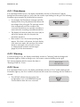
4.4.1 Disturbance
If an operational failure occurs, the display immediately switches to "Disturbance" and the
background illumination lights up. In this case the inverter stops feeding into the grid. The following
illustrations give examples of possible failure scenarios.
• For example, this Disturbance message would be
displayed if the Sunny Boy detected a problem with
the voltage of the utility grid. The message would
clear automatically once the condition was
corrected. Disturbances are typically caused by a
measured value exceeding a predetermined limit.
• The display will show the value of the error (at:) as
well as the present value for the particular
parameter (present:).
• After another 5 sec. the normal operating data
appear. If the fault is still present, the fault display
cycle starts over again. An overview of the status
and error messages can be found in section
6 "Measurement channels and messages"
(page 26) of this documentation.
4.4.2 Warning
If a fault warning occurs, the display immediately switches to "Warning" and the background
illumination lights up. When warnings occur, the inverter continues feeding into the grid.
This warning appears after the inverter has been in
"Derating" mode for 10 min.
Warning
Derating
4.4.3 Error
If an operational failure occurs, the display immediately switches to "Error" and the background
illumination lights up. An Error condition will prevent the inverter from restarting until the condition is
cleared.
• "Error ROM" indicates that the inverter has
recognized an error in the EEPROM firmware.
Contact SMA to have the error corrected.
User Manual
SB_CL_US-BUS094410
23
Information on the display
SMA America, LLC
4.4.4 Rapid Blinking of background illumination
DC Overvoltage
If an excessive DC input voltage is present at the Sunny
Boy, this is indicated by rapid blinking of the background
illumination and the message shown on the right.
NOTICE
DC input voltage too high. Destruction of the inverter.
• Contact your installer, who will immediately disconnect the PV generator from the
inverter and check the DC voltage, as described in the inverter installation guide.
24
SB_CL_US-BUS094410
User Manual
SMA America, LLC
Maintenance and cleaning
5 Maintenance and cleaning
Check the correct operation of the inverter at regular intervals. Impurities such as dust or pollen can
cause heat accumulation that can lead to yield losses. Also check the inverters and the cables for
visible external damage. Have repairs carried out if necessary.
5.1 Checking heat dissipation
5.1.1 Cleaning the fans
If the fan guards are only covered with loose dust, they can be cleaned with a vacuum cleaner. If
vacuum cleaning does not produce a satisfactory result, contact your installer, who will dismantle the
fans for cleaning.
• The fan cleaning procedure is described in the respective installation guide and must be carried
out by qualified personnel.
5.2 Cleaning the display
If the display or the status LEDs are so soiled that they can no longer be read, they should be cleaned
with a damp cloth.
• Never use solvents, abrasives or corrosive materials for cleaning.
User Manual
SB_CL_US-BUS094410
25
Measurement channels and messages
SMA America, LLC
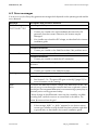
6 Measurement channels and messages
If your inverter is equipped with a communication component, then numerous measurement channels
and messages to aid diagnosis can be transmitted.
The following abbreviations apply:
BFR: Operation control unit
SRR: Current control unit
The BFR and SRR are redundant processor control systems for the utility protection functions.
6.1 Measuring channels
Measuring
channel
Balancer
CO2 saved
E-total
Error
Event-Cnt
Fac
Grid Type
h-On
h-total
I-dif
Iac
Inv.TmpVal
Ipv
Max Vpv
Mode
Pac
Pcb.Tmp.Val
Power On
Riso
Serial Number
Vac
Vac L1
Vac L2
26
Description
Displays the currently active operating mode of the Sunny Boy, which has been
set via the operating parameter "PowerBalancer".
Amount CO2 saved in operation time
Total amount of energy fed into the grid
Identification of the current disturbance / error.
Counter of events which have occurred
Grid frequency
Type of grid the inverter is connected to
h-on indicates how long sufficient DC voltage has been applied to the Sunny
Boy and the Sunny Boy has been active including the time it was not able to
feed to the utility with respect to low DC voltage or operation in stop mode.
Total number of grid-feeding operational hours
Differential current of the PV system (inverter and PV generator)
Grid current (active current)
Temperature measured at IGBT module
PV current
Maximum PV input voltage
Display of the current operating mode
Generated AC power
Temperature measured at PCB board
Total system start-up counter
Insulation resistance of the PV system before grid connection
Serial number of inverter
Grid voltage L1 - L2
Grid voltage L1 - N
Grid voltage L2 - N
SB_CL_US-BUS094410
User Manual
SMA America, LLC
Measuring
channel
Vfan
Vpv
Vpv-Setpoint
Measurement channels and messages
Description
Fan supply voltage
PV input voltage
PV target voltage
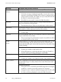
6.2 Status Messages
The inverters can be in various operating modes. These are displayed as status messages which can
vary according to the method of communication.
Message
Balanced
Description and corrective measure
The Sunny BoyBoy has disconnected from the grid, or is limiting its output to
6 kW (adustable with parameter PowerBalMax) over a 10-minute average. The
Sunny Boy is part of a three-phase system equipped with two further Sunny Boys
and the SMA Power Balancer to avoid unbalanced load. The "Balanced" message
is displayed for the following reasons:
Case 1:
The operating parameter "PowerBalancer" is set to "PhaseGuard". One of the three
Sunny Boy inverters in this system has indicated a grid fault and disconnected from
the grid. Consequently, the other two Sunny Boy inverters also disconnect from the
grid to avoid an unbalanced load, and send the message "Balanced".
Case 2:
The operating parameter "PowerBalancer" is set to "PowerGuard". One of the
3 Sunny Boys in this system has detected a device or grid fault and disconnected
from the grid. The two remaining Sunny Boys reduce their output over a 10-minute
average to 6 kW (adustable with parameter PowerBalMax) in order to prevent an
unbalanced load.
Case 3:
The operating parameter "PowerBalancer" is set to "FaultGuard". One of the 3
Sunny Boys in this system has indicated a device or grid fault and disconnected
from the grid.
When grid failure occurs, the other two Sunny Boys also disconnect from the grid
to prevent an unbalanced load, and send the message "Balanced".
In the event of a device fault, the fault message is sent to the other two devices with
a time lapse of 5 min. After the 5 min. have passed, the other two devices
disconnect from the grid and send the message "Balanced".
User Manual
SB_CL_US-BUS094410
27
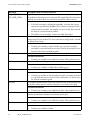
Measurement channels and messages
Message
Derating
SMA America, LLC
Description and corrective measure
Overtemperature in the inverter.
The inverter reduces its output to prevent the device from overheating.
Corrective measures
• In the case of fan devices check heat dissipation, as described in section
5.1 "Checking heat dissipation" (page 25).
• To avoid unnecessary yield losses, your installer must check the configuration
and string size.
Disturbance
• The installer should also check whether the inverter could be installed in a
better position with better ventilation and adequate heat dissipation.
Disturbance. This error is generated for safety reasons and prevents the Sunny Boy
from connecting to the grid.
Corrective measures
Error
• Contact your installer or SMA.
An error has been detected.
Corrective measures
• Contact your installer or SMA.
Testing the grid status, relay test etc.
Grid
Monitoring
MPP-Search
Offset
Riso
Stop
V-Const
This message occurs during the startup phase before the Sunny Boy has connected
to the grid. The message usually appears in the morning and evening when there is
little solar irradiation. Grid monitoring is also carried out after a fault has occurred.
The Sunny Boy is operating in MPP mode. It extracts the highest possible power
output from the PV generator. MPP is the standard display message when operating
under normal irradiation conditions.
The inverter is calculating the MPP (Maximum Power Point)
Offset calibration of the electronics (at start-up).
Measurement of the insulation resistance of the PV system.
Interruption of operation after a disturbance. This status can also be set manually.
Constant-voltage operation ("Const. Volt.")
Waiting
Warning
The input voltage of the PV array is set at a given nominal value and the inverter is
not operating in MPP mode. In some cases this mode can be set as the operating
mode.
PV voltage is not high enough to start.
System warning advising further investigation.
MPP
28
SB_CL_US-BUS094410
User Manual
SMA America, LLC
Measurement channels and messages
6.3 Error messages
If an error occurs, the Sunny Boy generate a message which depends on the operating mode and the
error detected.
Message
!PV-Overvoltage!
!DISCONNECT DC!
Description and corrective measure
Overvoltage at DC input.
Corrective measures
• Contact your installer who will immediately disconnect the PV
generator from the inverter! Otherwise, the inverter may be
damaged.
CAN
Check L-N-PE
DC link
• Your installer must check the DC voltage, as described in the inverter
installation guide.
Internal communication fault.
Corrective measures
• Contact your installer or the SMA Serviceline if this problem recurs.
L and N are swapped on the AC connection or PE is not connected.
Corrective measures
• Contact your installer to check the AC connection.
The internal hardware monitoring system has detected a fault in the power
electronics.
Corrective measures
Derating
• Contact your installer or the SMA Serviceline.
The inverter reduces the output power due to high internal temperature.
Corrective measures
dI-Bfr
• See Section 3.1.6 "The green LED goes out briefly" (page 15) for
more information on this warning.
The inverter has detected a drastic change in the differential current. This
fault only occurs in transformerless inverters that have no galvanic isolation
from the grid. The integrated differential current monitoring system plays an
important part in ensuring personal safety.
dI-Srr
A drastic change in the differential current can be caused by a sudden
grounding fault, residual current or an actual fault in the device. The
inverter disconnects from the grid.
Corrective measures
• If the message „dI-Bfr“ or „dI-Srr“ appears for no obvious reason,
contact your installer to verify whether the plant insulation might have
a ground fault, as described in the inverter installation guide.
User Manual
SB_CL_US-BUS094410
29
Measurement channels and messages
Message
dI-Meas-Srr
SMA America, LLC
Description and corrective measure
Deviation in the differential current measurement / differential current
Corrective measures
dI-Meas
• If this fault message is displayed repeatedly, it means that inverter
operation is permanently disabled. If the inverter is equipped with a
communication interface, the installer can try to rectify the fault with
the help of a communication product.
• Should this be unsuccessful, contact the SMA Serviceline.
Transition disturbance during reading or writing of EEPROM data. This
data is not essential for safe operation.
EEPROM
• The disturbance has no effect on the performance of the inverter.
Data EEPROM defective, device is set to permanent disable due to the fact
that the data loss affects important functions of the inverter.
Corrective measures
EEPROM p
• Contact SMA.
One of the duplicate data sets in the EEPROM is defective and has been
reconstructed without loss of data.
EeRestore
• This error message is for information purposes only and has no effect
on the performance of the inverter.
The grid frequency is no longer within the permissible range ("Bfr" or "Srr"
is an internal message with no relevance for the user). The Sunny Boy
assumes that the public grid is down and disconnects from the grid in order
to avoid islanding.
Corrective measures
Fac-Bfr
Fac-Srr
• Contact your installer to deal with the fault.
• If the grid frequency is within the tolerance range, yet "Fac-Bfr" or
"Fac-Srr" faults are still being displayed, contact SMA.
Internal measurement fault or hardware defect.
Corrective measures
HW-Signal
Iac-DC_Offs-Srr
• Contact your installer or the SMA Serviceline if this problem recurs.
The DC component of the electricity being fed into the grid has exceeded
the permissible range. For safety reasons, the inverter disconnects itself
from the grid.
Corrective measures
• If the grid current is outside the permissible range due to local grid
conditions, contact the local utility operator for assistance.
• If the grid current is within the tolerance range, yet the "Iac-DC_OffsSrr" fault is still being displayed, contact the SMA Serviceline.
30
SB_CL_US-BUS094410
User Manual
SMA America, LLC
Message
IGBTs
Measurement channels and messages
Description and corrective measure
The internal hardware monitoring system has detected a fault in the power
electronics.
Corrective measures
MSD-FAC
• Contact your installer or the SMA Serviceline.
Internal measurement comparison fault or hardware defect.
Corrective measures
MSD-Idif
• Contact your installer or SMA if this problem recurs.
Internal measurement comparison fault or hardware defect.
Corrective measures
MSD-VAC
• Contact your installer or SMA if this problem recurs.
Internal measurement comparison fault or hardware defect.
Corrective measures
MSD-Timeout
• Contact your installer or SMA if this problem recurs.
Internal measurement comparison fault or hardware defect.
Corrective measures
Offset
• Contact your installer or the SMA Serviceline if this problem recurs.
Fault in the acquisition of measurement data.
Corrective measures
PowerBalancer
REL_INV_CLOSE
REL_GRID_CLOSE
• Contact your installer or SMA if this problem recurs.
The Sunny Boy is part of a three-phase system with two further Sunny Boys.
This is equipped with the SMA Power Balancer for preventing unbalanced
loads. The operating parameter "PowerBalancer" is set to "PhaseGuard" or
"FaultGuard".
Corrective measures
• For more detailed descriptions of the operation modes
„PhaseGuard“ and „FaultGuard“ refer to section 6.2 "Status
Messages" (page 25) under „Balanced“.
A grid relay does not close. The inverter checks the relays connecting it to
the grid before feeding power into the grid. If the grid relays do not function
properly, the inverter does not connect to the grid for safety reasons.
Corrective measures
• If this fault message is displayed repeatedly, it means that inverter
operation is permanently disabled. If the inverter is equipped with a
communication interface, the installer can try to rectify the fault with
the help of a communication product.
• Should this be unsuccessful, contact the SMA Serviceline.
User Manual
SB_CL_US-BUS094410
31
Measurement channels and messages
Message
REL_INV_OPEN
REL_GRID_OPEN
SMA America, LLC
Description and corrective measure
A grid relay does not open. The inverter checks the relays connecting it to
the grid before feeding power into the grid. If the grid relays do not function
properly, the inverter does not connect to the grid for safety reasons.
Corrective measures
• If this fault message is displayed repeatedly, it means that inverter
operation is permanently disabled. If the inverter is equipped with a
communication interface, the installer can try to rectify the fault with
the help of a communication product.
• Should this be unsuccessful, contact the SMA Serviceline.
The electrical insulation of the PV system to ground is faulty. The resistance
between the DC plus and/or DC minus connection and ground is outside
the defined limit range.
Corrective measures
Riso
• Contact your installer to check whether your system is properly
insulated or a ground fault has occurred. Further information is to be
found in the inverter installation guide.
The insulation measurement has failed.
Corrective measures
Riso-Sense
ROM
• Contact your installer or the SMA Serviceline if this problem recurs.
The inverter firmware is faulty.
Corrective measures
SD-DI-Conv
• Contact your installer or SMA if this problem recurs.
The inverter has detected an insulation fault on the DC side.
Corrective measures
• Contact your installer to check whether the plant is properly insulated
or a ground fault has occurred. Further information is to be found in
the inverter installation guide.
The inverter has detected an overcurrent on the AC side. It disconnects from
the grid for safety reasons and then attempts to reconnect to the grid.
Corrective measures
SD-Imax
SD-INV-Bridge
Shutdown
• Contact your installer or the SMA Serviceline if this problem recurs.
The inverter has detected a fault in the power electronics. It disconnects
from the grid and then attempts to reconnect to the grid.
Corrective measures
• Contact your installer or the SMA Serviceline if this problem recurs.
Temporary inverter fault.
Corrective measures
• Contact your installer or SMA.
32
SB_CL_US-BUS094410
User Manual
SMA America, LLC
Message
STM-Timeout
Vac-Bfr
Vac-Srr
Measurement channels and messages
Description and corrective measure
Internal program run fault.
Corrective measures
• Please contact your installer or the SMA Serviceline if this problem
recurs.
The grid voltage is no longer within the permissible range ("Bfr" or "Srr" is
an internal message that has no meaning for the user). This can be caused
by any of the following:
• Grid disconnected (line circuit breaker, fuse),
• AC cable is broken or
• AC cable is highly resistive
For safety reasons, the inverter disconnects itself from the grid.
Corrective measures
• Contact your installer to check the grid voltage and the grid
connection at the inverter.
• If the grid voltage is outside the acceptable range due to local grid
conditions, your installer should ask the utility operator whether the
voltage can be adjusted at the feed-in point or whether they would
agree to modifications in the monitored operational limits (operating
parameters: Vac-Min and Vac-Max).
VacL1-Bfr
VacL1-Srr
• If the grid frequency is within the tolerable range, yet "Vac-Bfr," or
"Vac-Srr" faults are still being displayed, contact SMA.
The grid voltage on line 1 is no longer within the permissible range ("Bfr"
or "Srr" is an internal message that has no meaning for the user). This can
be caused by any of the following:
• Grid disconnected (line circuit breaker, fuse),
• AC cable is broken or
• AC cable is highly resistive
For safety reasons, the inverter disconnects itself from the grid.
Corrective measures
• Contact your installer to check the grid voltage and the grid
connection at the inverter.
• If the grid voltage is outside the acceptable range due to local grid
conditions, your installer must ask the utility operator whether the
voltage can be adjusted at the feed-in point or whether they would
agree to modifications in the monitored operational limits (operating
parameters: Vac-Min and Vac-Max).
• If the grid frequency is within the tolerable range, yet "Vac-Bfr," or
"Vac-Srr" faults are still being displayed, contact SMA.
User Manual
SB_CL_US-BUS094410
33
Measurement channels and messages
Message
VacL2-Bfr
SMA America, LLC
Description and corrective measure
The grid voltage on line 2 is no longer within the permissible range ("Bfr"
or "Srr" is an internal message that has no meaning for the user). This can
be caused by any of the following:
VacL2-Srr
• Grid disconnected (line circuit breaker, fuse),
• AC cable is broken or
• AC cable is highly resistive
For safety reasons, the inverter disconnects itself from the grid.
Corrective measures
• Contact your installer to check the grid voltage and the grid
connection at the inverter.
• If the grid voltage is outside the acceptable range due to local grid
conditions, your installer must ask the utility operator whether the
voltage can be adjusted at the feed-in point or whether they would
agree to modifications in the monitored operational limits (operating
parameters: Vac-Min and Vac-Max).
VdclinkMax
• If the grid frequency is within the tolerable range, yet "Vac-Bfr," or
"Vac-Srr" faults are still being displayed, contact SMA.
The internal hardware monitor has detected an overvoltage condition in
the intermediate circuit of the inverter.
Corrective measures
VpvMax
• Contact your installer or the SMA Serviceline if this problem recurs.
Overvoltage at DC input.
Corrective measures
• Contact your installer who will immediately disconnect the PV
generator from the inverter! Otherwise, the inverter may be
damaged.
Watchdog
Watchdog Srr
• Your installer must check the DC voltage, as described in the inverter
installation guide.
Internal program run fault.
Corrective measures
• Contact your installer or the SMA Serviceline if this problem recurs.
34
SB_CL_US-BUS094410
User Manual
SMA America, LLC
Glossary
7 Glossary
AC
Abbreviation for "Alternating Current"
DC
Abbreviation for "Direct Current"
Derating
A controlled reduction in performance, usually dependent on component temperatures. Compared
with the (also common) practice of completely shutting down the device, derating has a less drastic
effect on the external grid.
Grid-connected system
PV system which is connected to the power supply grid of an external energy supplier.
Grid impedance
The grid impedance is a characteristic grid specification, which is determined both by the grid
infrastructure, and by the number of power suppliers and power consumers. If supply to the grid
section drops due to a grid shutdown on the part of the adjacent energy suppliers (medium-voltage
transformers), the grid impedance changes abruptly. In order to detect this occurrence, and to prevent
the formation of an unwanted stand-alone grid, SMA Grid Guard monitors the grid impedance and
disconnects the inverter from the grid in the event of a sudden impedance variation.
Inverter
A device for converting the direct current (DC) from the PV generator into alternating current (AC),
which is used by most normal household devices, and especially for feeding energy into an existing
supply grid.
Maximum Power Point "MPP"
The operating point (current / voltage) of the PV generator at which the highest possible performance
under the prevailing conditions is achieved. The actual MPP changes constantly, depending on the
level of solar irradiation, cell temperature, etc.
MPP tracker
A device that adjusts the voltage and current of a PV generator so that it operates at its
"Maximum Power Point".
PV
Abbreviation for "photovoltaic" describing the conversion of solar energy into electrical energy.
PV generator
Technical device for the conversion of solar energy into electrical energy. This normally refers to all
installed and electrically connected PV modules in a PV system.
User Manual
SB_CL_US-BUS094410
35
Glossary
SMA America, LLC
PV module
A collection of solar cells in an enclosure that protects the sensitive cells from mechanical stress and
allows easy installation.
SMA Grid Guard
The SMA Grid Guard concept monitors, for instance, the voltage and frequency of the connected AC
grid according to predefined parameters. This serves to prevent the formation of a stand-alone grid
in the event of grid disconnection.
SMA Power Balancer
The SMA Power Balancer is a serial feature of the Sunny Boy. The SMA Power Balancer prevents the
formation of an unbalanced load during three-phase grid feeding. To this effect, a group made up of
3 Sunny Boys are each connected via a control line to a 3-phase feeding unit.
Solar cell
An electronic component which generates electrical energy when irradiated with sunlight. Since the
voltage produced by a single solar cell is very small (approx. 0.5 V), several solar cells are combined
to form a PV module.
Solar energy
"Sun energy", i.e. energy from sunlight (solar irradiation).
PV power plant
Describes the totality of components required for the exploitation and utilization of solar energy. In
grid-connected systems this includes not only the PV generator, but also the inverter, e.g. Sunny Boy.
String
Describes a group of series-connected PV modules.
String inverter
In string technology, the PV generator is subdivided into individual module surfaces, or "strings", each
of which has an assigned string inverter. This technology reduces system costs while at the same time
making installation a lot simpler and increasing the energy yield and system availability.
Unbalanced load
The difference between the power fed into the grid at the individual phase conductors.
36
SB_CL_US-BUS094410
User Manual
SMA America, LLC
Contact
8 Contact
If you have technical problems concerning our products, contact your installer or the SMA Serviceline.
We require the following information in order to provide you with the necessary assistance:
• Inverter type
• Type and number of modules connected
• Communication method
• Serial number of the Sunny Boy
• Failure or warning number of the Sunny Boy
• Display of the Sunny Boy
SMA Solar Technology America, LLC
4031 Alvis Court
Rocklin, CA 95677
Tel. +1 916 625 0870
Tel. +1 877-MY SMA TECH
Tel. +1 877 697 6283 (Toll free, available for USA, Canada and Puerto Rico)
Fax +1 916 625 0871
[email protected]
www.SMA-America.com
User Manual
SB_CL_US-BUS094410
37
4.""NFSJDB--$
XXX4.""NFSJDBDPN