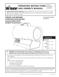
1
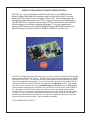
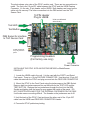
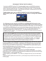
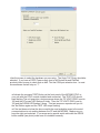
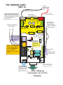
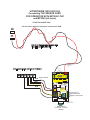
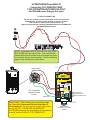
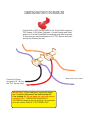
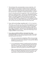
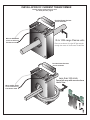
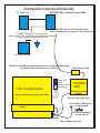
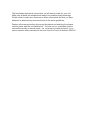
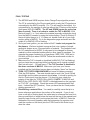
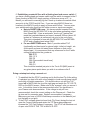
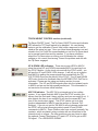
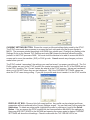
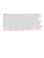
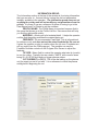
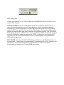
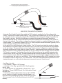
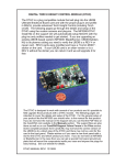
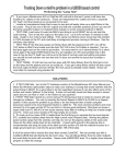
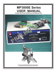
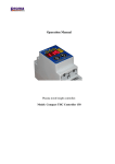
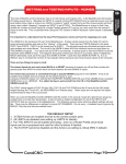
DTHC-SETUP/INSTALL
MANUAL REV3
For use with the following CandCNC products:
UBOBII Builders Kit
UBOB III Builders Kit
MP3000 rev B or later
BladeRunner (all versions)
Use this manual to install and setup a DTHC Expansion
Module in the field for any of the above listed CandCNC
products OR to setup and test the DTHC functions in a
a CandCNC Product that already has the DTHC Module
installed.
CandCNC
May 15th 2010
DIGITAL TORCH HEIGHT CONTROL MODULE (DTHC)
The DTHC is a plug compatible module that will plug into the UBOB Ultimate
BreakOut Board card and with the proper plug-in and profile in MACH, provide
advanced Torch Height Control (including Torch on/off). The following pages go
through the details and setup of the DTHC using the custom screens and plug-ins.
The MP3000-DTHC Install file on the support CD will automatically setup MACH3
with the plug-ins and profiles needed to get started. If you are upgrading an
existing UBOB based system (MP3000; BladeRunner; UBOB Builders Kit) to do
plasma cutting you need to verify the UBOB is a UBOB III or newer card.
The DTHC is designed to work with several of our products and it’s possible to field upgrade
those products with a DTHC module. The following pages are intended to cover the details
and setup of the DTHC. For the general setup of your product like the MP3000 you should
refer to the manual for that product. If you do not have the manual or the Support CD you
can find the PDF files on the CandCNC.com website in the Manuals section. The support
files are also there as well as on our CandCNCSupport Yahoo Forum in the Files section.
Some complete products from CandCNC may not have the correct version of the UBOB to
do a direct plug of the DTHC and there may not be a slot for the card in the front panel.
Please advise us if you need a new front panel with a slot for the DTHC and which product
you have. If you do not have an MP3000 or BladeRunner in the case then you can get a
special front panel amuminum plate that will mount the components inside your case and
expose the plugs for easy hookup. See our website for details.
DTHC MANUAL REV3 5/16/10
The photo shows a top view of the DTHC module card. There are two connections to
make. The first is the 16 pin IDC cable between the DTHC and the UBOB Feature
Connector. It’s the only 16 pin header on the UBOB. Both headers are keyed so the
cable only fits one way. The other connection is to the DB9 socket from the THC
Sensor Card.
16 PIN Header
Plug to UBOB
Units are calibrated
at the factory.
Test LED
Test Button
DB9 Socket for interface
to THC Sensor Card
Actual card layout
may vary from the
photo.
Programming Headers
(For factory use only)
DC to DC
Power Converter
INSTALLING THE DTHC INTO AN EXISTING MP3000 or BladeRunner
PRODUCT
1. Locate the UBOB card in the unit. It is the card with the PORT1 and Serial
Port inputs. There is a 16 pin FEATURE CONNECTOR. Use the short 16 pin IDC
cable included with the DTHC and plug one end into the FEATURE CONNECTOR
2. Mount the DTHC to the Front Panel using the jackscrews on the DB9 Socket.
Remove both hex jackscrews and line up the holes for the TEST LED and the
TEST BUTTON. Replace the hex jackscrews through the front into the DB9
Socket and tighten until the board is snug against the inside of the panel. DO
NOT OVERTIGHTEN AND STRIP THE INTERNAL FASTENERS ON THE DB9!
It will make secure mounting difficult. The threads on the jackscrews are 4-40.
3. Hold the back of the DTHC Card and insert the other end of the 16 pin IDC
cable from the UBOB card FEATURE CONNECTOR Header.
4. Proceed to DTHC preliminary testing
PRELIMINARY TESTING THE DTHC MODULE:
If you have an MP3000 with the DTHC already installed, power up the MP3000 and using a
small probe (stiff wire, paperclip, etc push the TEST Button that is recessed behind the front
panel. Press and release one time. The yellow LED should start to flash. If it does not check
the AC cord and plug and try again. If the LED lights and flashes it indicates that the DTHC has
power and the on-board processor is working.
Further testing requires you have MACH3 installed, the serial cable attached and the
MP3000-DHTC profile and screen set loaded. See the section on Loading DTHC DRIVERS
Below.
LOADING DTHC DRIVERS/PLUG-INS
The Following assumes that the auto INSTALL for the MP3000 (MP3000-Install) unit has
been done and the basic profile has been checked and the Basic screens have been tested.
If they have not, refer to the MP3000 User Manual and perform those steps. If you are building up
a unit (UBOB or UBOB Builders Kit) you need to refer to those manuals for the base setup. All of
the plug-ins will be loaded during the base install but the DTHC install adds addtional screens,
MACH profiles and Icons to use with the DTHC. The communication drivers need to be
configured for DTHC interface. The following steps will take you through setting up the system to
use with the DTHC module.
UPDATE: Any unit shipped after 2/25/2010 has a new auto-installer that puts both the Basic
(router/mill) and the DTHC (plasma) profiles and their related screens and drivers on the PC in
MACH and does NOT need the update install. IF your desktop has both the MP3000-DTHC or
the BladeRunner Dragon-Cut shortcuts then you do not need tho do the DTHC Upgrade install
listed below. All current units being shipped have the updated auto installer. The update for
DTHC procedure is included for users that have an older MP3000, BladeRunner, or UBOB
Builders Kit and are adding a DTHC module for plasma cutting in the Field.
? From the Support CD (or a web download locate the MP3000E-DTHC_INSTALL file. Run it in
Windows with MACH3 NOT RUNNING. It will place an MP3000-DTHC icon on the desktop that
will Start MACH with the correct profile instead of having to use MACH Loader each time. It will
add and configure the MACH com objects (driver). The MP3000-DTHC profile in MACH will be
added along with the matching screen sets and macros.
?After the MP3000-DTHC Install open MACH3 using either the MP3000-DTHC Icon OR from the
matching named profile in the MACH Loader.
?If you re-install MACH or upgrade, you may need to run the DTHC-Install again.
?Open MACH using the MP3000-DTHC profile and select CONFIG PLUGINS from the CONFIG
menu in the top row. You will se a list of plugins that are available At the topof the list are the three
CandCNC plugi-ins. Each one starts with “ccc_”
?Confirm that they are all ENABLED. If you make any changes make sure you close and restart
MACH.
?Click the CONFIG (yellow) text next to the ccc_comm plugin and you will see the screen on the
following page:
?Use the screen to select the hardware you are using. The Ubob THC Plugin should be
selected. If you have a ESPC Power supply (part of all RouterPak and PlazPak
products) then be sure to check that as well. Not the COM port selection box. In most
circumstances that will stay on “1”.
AActivate the recessed TEST Button on the front panel of the MP3000-DTHC or
your unit with the DTHC module installed and connected. The TEST LED should
start flashing.The unit goes into a test sequence where the TIP VOLTS DRO is set to
100 and the UP screen LED flashes 5 times. Then the TIP VOLTS DRO is set to
150 and the DOWN LED flashes 5 times. This test sequence repeats until you hit
the Test Button again and the TEST LED stops flashing.
AIf the test does not show the above results the most probable cause is the serial
communications is not working between the PC and the MP3000. Make sure you
have the right port selected. If you were sent a special serial cable with the RS232
buffer module (see photo) make sure it is installed correctly.
OBSOLETE CARD
THC Sensor Card REV12A
Use with MP1000B; MP1000C; MP3000-DTHC; DTHC Module.
Signal Status
LED’s- see
instructions
To TORCH SWITCH
CIRCUIT in PLASMA
Fires the torch From CT for
RAW TIPS Volts
Input (CAUTION
HIGH VOLTAGE
when torch is ON
Arc OK
Sensitivity
Adjust
(CT input
ONLY)
Arc OK - see
instructions
DB9 Cable
From
DTHC
Card
No Polarity on any signals
From Plasma Unit
Arc Ok (Dry Contacts)
output.
The THC Sensor card pictured above is mounted at the plasma unit and the
process is covered in the MP3000-DTHC manual and in the following pages.
Each plasma unit is slightly different so we cannot give specifics as to where to
make the connections. We have included the information on the Hypertherm
1000 series. If you have another model or brand you can contact us if you have
problems locating the signals you need. The THC Sensor needs the:
? Raw Tip Volts (undivided voltage) between the electrode wire and the
workclamp).
? an ARC OK switch (dry contact) or if your plasma does not have an Arc OK
(Arc Xfer; OK to Move, etc) signal you can access, then you will need to order
the optional CT transformer (part #CT-01) from us and make the proper
connections on the THC Sensor card.
?Torch Start. The final signal is an output from the THC Sensor Card to start
the torch (basically low current isolated relay contacts). On some plasma units
with machine torches you can fire the torch remotely by closing a switch across
two terminals. The Torch Switch output on the THC Sensor card does that. On
others you will have to find the actual Torch Switch wires in the Torch cable
THC SENSOR CARD
REV 14
DAMGER
HIGH VOLTAGE
WHEN TORCH
is ON
To TORCH (ELECTRODE WIRES)
Mount card at least ½”from any
Metal. Use ½”or longer standoffs
above metal case Do not let shell
of DB9 contact metal of
Plasma Case
TO TORCH POS
(WORKCLAMP WIRE)
Spark Gap
For HV Systems
J16
J17
J14
TO ARC XFR
[OK to Move]
Relay Contacts
(DRY CONTACTS)
D13
R1
NO POLARITY
J15
RV1
R7
Tip
Volts
Workclamp
+ [POS]
L4
- [NEG]
Tip Volts
Electrode
TORCH SWITCH
CAUTION!
HIGH VOLTAGE
D6
CAUTION!
HIGH VOLTAGE
CAUTION!
HIGH VOLTAGE
C1
NO POLARITY
R8
R6
THC Sensor
REV 14
R2
Volts
D22
Switch
Torch
Switch
Torch
CandCNC
ARC OK LED
ACTIVE ONLY
WHEN CT INPUT
is USED.
J10
D21
36
L2
C2
J3
Arc OK[V]
ARC OK
DCP
TORCH RELAY
ARC OK
Input Jack
for
Digital Current
Probe (DCP)
+
Arc
OK
5
TP1
TP4
J4
TP3
J1
J5
TORCH
ACTIVE
D2
NOTE: BOARD Lettering
(silkscreen) on REV14
cards is REVERSED
For J11 and J10.
J10 is the Torch Switch
Wires
L1
J11
37
FOR CT (Current
Transformer) Input
Only. See page
information
1
VR2
39
38
SENSIVITY ADJUST
FOR ARC OK FROM
CT Transformer ONLY
Not used with other
ARC OK methods
PLUG
9
TP2
6
TP1 - TP2 Test voltage:
When torch fired = approx
1/7 of Rat TIP VOLTS.
DB9 Cable to
Connector on DTHC
Module
HYPERTHERM 1000/1250/1650
Connecting THC SENSOR CARD
FOR OPERATION WITH MP1000C-THC
and MP3000 (all series)
TIP VOLTS CONNECTION
J15 and J16 are Slide-on connectors located on the PCB
J15
J16
Use 18 or 20ga insulated Hookup wire
Insulation rating to 400V Min
DAMGER
HIGH VOLTAGE
WHEN TORCH
is ON
To TORCH (ELECTRODE WIRES)
J19 Located inside Cabinet on PC Board
Spark Gap
For HV Systems
J16
J17
J15
L4
J14
RV1
D13
R1
WHT START SIGNAL
R7
Tip
Volts
Workclamp
+ [POS]
- [NEG]
Tip Volts
Electrode
CAUTION!
HIGH VOLTAGE
D6
CAUTION!
HIGH VOLTAGE
CAUTION!
HIGH VOLTAGE
C1
RED
R8
R6
L2
THC Sensor
REV 14
R2
Volts
D22
Switch
Torch
Switch
Torch
CandCNC
ARC OK LED
ACTIVE ONLY
WHEN CT INPUT
is USED.
J10
D21
36
L1
C2
J3
Arc OK[V]
ARC OK
DCP
ARC OK
Connector for
OPTIONAL DCP
Digital Current Probe
+
TORCH RELAY
ARC XFR
J11
BLK
37
YEL
Arc
J4
OK
5
TP1
TP4
J5
TP3
J1
D2
TORCH
ACTIVE
1
39
38
PLUG
9
TP2
6
VR2
TP1 - TP2 Test voltage:
When torch fired = approx
1/7 of Raw TIP VOLTS.
DB9 Cable to
Connector on DTHC
Module
CONNECTIONS FOR SYSTEMS USING CT TRANSFORMER
THC SENSOR CARD
REV 14
DAMGER
HIGH VOLTAGE
WHEN TORCH
is ON
To TORCH (ELECTRODE WIRES)
Mount card at least 6½”from any
9
Metal. UseVR2½”or longer standoffs
above metal case Do not let shell
of DB9 contact metal of
Plasma Case
TO TORCH POS
(WORKCLAMP WIRE)
Spark Gap
For HV Systems
J16
J17
J14
R1
D13
D6
CAUTION!
HIGH VOLTAGE
CAUTION!
HIGH VOLTAGE
FOR CT (Current
Transformer) Input
Only. See page
information
J15
RV1
R7
Tip
Volts
Workclamp
+ [POS]
L4
- [NEG]
Tip Volts
Electrode
CAUTION!
HIGH VOLTAGE
C1
R8
R6
R2
Volts
Switch
Torch
Switch
Torch
J10
ARC OK LED
ACTIVE ONLY
WHEN CT INPUT
is USED.
DCP
ARC OK
+
Arc
TP4
J4
OK
5
TP1
1
J5
J1
D2
TORCH
ACTIVE
TP3
TORCH RELAY
THC Sensor
REV 14
J3
Arc OK[V]
ARC OK
CandCNC
D21
36
L2
L1
J11
37
C2
D22
TP2
39
SENSIVITY ADJUST
FOR ARC OK FROM
CT Transformer ONLY
Not used with other
ARC OK methods
TP1 - TP2 Test voltage:
When torch fired = approx
1/7th of Raw TIP VOLTS.
(Divide by 7 circuit)
DB9 Cable to
Connector on DTHC
Module
CT Transformer is an OPTION and must be ordered separately. It is used on Plasma
Cutters that do not have an available ARC OK (Called other names by different
Plasma manufacturers). The ARC OK provides feedback to the control that a valid
pierce has been made and the arc current is at a level where motion can be released
and the cut begun. The ARC OK is used only when the control has the THC enabled
(Screen button). IT IS REQUIRED for Automated cutting with THC. All CandCNC
THC Sensor cards have had the ability to use an external Current Transformer (CT)
placed in the AC line to the plasma. The CT will only sense AC current so cannot be
used on the DC side of the plasma. A new DC Current Probe (DCP) will be
introduced in 2009 (late summer) that will read and sense the actual DC current at the
WorkClamp lead and the REV14 card has the pads for the connector that will
interface the DCP (Digital Current Probe) through the THC Sensor. To use the DCP
you will have to have a DTHC Module Rev 8 or later. You can trade in older DTHC
modules for the upgrade when you purchase a new DCP module.
HYPERTHERM PowerMAX 45
Connecting THC SENSOR CARD
FOR OPERATION WITH MP3000-DTHC
and BladeRunner Dragon-Cut seris
TIP VOLTS CONNECTION
J19 and J21 are Screw connectors located on the PCB inside the
PowerMAX 45. See the location drawing next page. Detailed
instructions for making these connections are in
https://www.hypertherm.com/library/files/Manuals/Service%20Manual%
20%28SM%29/806110r0.pdf
J21
J19
Use 18 or 20ga insulated Hookup wire
Insulation rating to 600V Min, Twist wires
along the length of the run.
NOTE: Hypertherm START (remote torch fire) DOES
NOT WORK with the Hand Torch. You must find the
Switch wires from the Hand torch and splice into them
to be able to fire the torch remotely. See the following
page to help identify the correct wires.
DAMGER
HIGH VOLTAGE
WHEN TORCH
is ON
To TORCH (ELECTRODE WIRES)
START SIGNAL
Spark Gap
For HV Systems
J16
J17
J14
R1
D13
D6
CAUTION!
HIGH VOLTAGE
CAUTION!
HIGH VOLTAGE
C1
12
J15
RV1
R7
Tip
Volts
Workclamp
+ [POS]
CAUTION!
HIGH VOLTAGE
L4
4
- [NEG]
Tip Volts
Electrode
3
R8
R6
THC Sensor
REV 14
R2
Switch
Torch
Switch
Torch
CandCNC
ARC OK LED
ACTIVE ONLY
WHEN CT INPUT
is USED.
J10
DCP
Connector for
OPTIONAL DCP
Digital Current Probe
+
TORCH RELAY
ARC OK
Arc
J4
OK
5
TP1
TP4
J5
TP3
J1
D2
TORCH
ACTIVE
1
39
38
PLUG
9
TP2
6
VR2
IMPORTANT: When making any connection inside
the PowerMAX disconnect the unit from the AC
Line (unplug it). Do not open the case with power
on the AC line. THERE ARE DANGEROUS
VOLTAGES present in the unit anytime it is connected
to an AC source EVEN IF IT IS TURNED OFF.
L2
D22
D21
36
Volts
ARC XFR
C2
J3
Arc OK[V]
ARC OK
J12 connector
located on rear
of unit.
L1
J11
37
14
TP1 - TP2 Test voltage:
When torch fired = approx
1/7 of Raw TIP VOLTS.
DB9 Cable to
Connector on DTHC
Module
CONNECTING HAND TORCH TO THC SENSOR CARD
Use ScotchLoc IDC Splices (RED) to tie Torch Switch output on
THC Sensor (J10) Screw Terminals. Locate Orange and Violet
wires at J10 in the PowerMAX box and tap each wire as shown.
To test short two screw terminals on J10 THC Sensor and torch
should fire (Plasma Unit on)
Connect to Screw
terminals J10 1 & 2 on
the THC Sensor Card
IMPORTANT: When making any connection inside
the PowerMAX disconnect the unit from the AC
Line (unplug it). Do not open the case with power
on the AC line. THERE ARE DANGEROUS
VOLTAGES present in the unit anytime it is connected
to an AC source EVEN IF IT IS TURNED OFF.
FROM HAND TORCH CABLE
HYPERTHERM PowerMAX 45
Connecting THC SENSOR CARD
FOR OPERATION WITH MP3000-DTHC
and BladeRunner Dragon-Cut seris
SIGNAL NAME(s)
POWERMAX
REF
THC
SENSOR
REV14 REF
NOTES
WIRE Type
TORCH SWITCH;
START - MECH
TORCH
PINS 3 & 4
J12
J10 Screw
Term 1 & 2
For use with mechanical
Torch ONLY.
18-22Ga stranded low
voltage insulated
TORCH SWITCH
HAND TORCH
ORG & VIO
wires at J10
J10 Screw
Term 1 & 2
Parallel taps where Torch
Cable Plugs into J10 in
PowerMax
18-22Ga stranded low
voltage insulated
ARC VOLTS; RAW
TIP VOLTS
J19 & J21
inside
Powermax45
J14 (neg) ,
J15 (pos)
This is NOT the 50:1
divided voltage at J12.
See detailed instructions
18-22 PVC stranded ,
insulted, twisted pair min
600V rated insulation
ARC OK ; ARC
XFR
PINS 12 & 14
J12
J4 & J5 ARC
OK Switch
Input
Dry Contact ouput from
PowerMAX (no voltage)
18-22Ga stranded low
voltage insulated
Drawign not to scale
LOCATION OF J19 and J21
Inside PowerMAX 45
FRONT
J19 or J18
(white wire)
TP 19
W
192 VDC
+ -
J2
1
CAUTION: Make sure wires
and terminals do not touch
anything but the screws for
J19 and J21. HIGH
VOLTAGE IS PRESENT
WHEN TORCH IS ON.
(w
o
rk
le
ad
TP 18
R
TP 17
B
192 VDC
+ -
)
To THC SENSOR CARD J14
NEG input terminal
To THC SENSOR CARD J15
POS input terminal
THC SENSOR CARD TESTING
Before you make connections to the plasma unit you may want to do some testing on to
confirm proper operation of the THC SENSOR with the DTHC Module.
? Set the THC SENSOR card on an insulated surface close to the DTHC and PC.
? Connect the THC SENSOR to the DB9 connector on the DTHC Module using a 25ft
DB9 Extension cable (all wires straight through).
? Load MACH and the MP3000-DTHC Profile and make sure you can come out of
RESET and that the CP (Charge Pump) LED on the front of the UBOB/MP3000 is ON.
? On some products you may have to have the Motor DC on to come out of RESET
? Click on the TORCH icon on the screen. You should see the LED above the TORCH
button on MACH turn on and there will be a click on the THC Sensor card and one of the
small LED’s on the card will light. That indicates the TORCH ON relay is working.
? The next check is to confirm the ARC OK circuit is working. Short across the J4 and J5
Terminals with a small screwdriver or jumper wire. The ARC OK LED on the MACH3
Screen should light. If it does you can proceed to the actual hookup of the THC SENSOR
card.
? If any of the tests fail make sure you have the cables firmly attached and that they are
the correct type. All of the cables we ship with any Package Deal are all “Extension” type
cables with all pins straight through.
? All cards are checked at least twice and most three times before they leave the factory.
It’s unusual for a THC SENSOR to be bad or fail in no load testing. If you have checked
all of the connections, cables and MACH setup and you still cannot get the THC SENSOR
to work contact us at 903-364-2740 or via e-mail at Tom @CandCNC.com
NOTE: Some Larger (>100A) plasma units or older smaller models use various methods
to start the initial ARC. Most common is HF (HIgh Frequency) start. HF Start presents
several challenges. It uses the concept that higher frequency waves travel through air
(and arc) easier than DC voltage. The HF is normally combined with a higher voltage and
it starts an ARC that the plasma uses to ignite the air. Once the arc fires if a conductive
part is close the arc will transfer to the material. The HF start causes a lot of noise and
current spikes. The other form of High voltage start is the CD (Capacitor discharge)
method. It is basically a high current version of an Automotive ignition system. Up to
30,000 volts can be generated. If the THC Sensor is not protected, the high voltage and
high frequency can cause component failure on the card or (worse) in the THC unit and
even burn the board. The THC Sensor (REV10 and up) is protected from HF and most
High Voltage start circuits. The REV 14 card has been introduced to work with any units
including units that use both HF and HV.
The smaller Hypertherm and other modern brand units use a low noise method called
“contact arc start”. The electrode is mounted against a spring that keeps it pushed
against the inside of the Nozzle as long as air is not flowing. When the unit is triggered
the starts a few milliseconds after the current starts to flow in the electrode circuit. As the
air flows it pulls the electrode away from the nozzle and creates an ARC. That is used
ionize the air and start the plasma.
The MP3000 can be used with all types of plasma units. The HF units tend to be very
noisy and some even have large amounts of RFI. The total isolation of the DTHC circuit
from any low level (PC logic) including any common ground stops any conducted noise.
The internal circuits are protected from RFI with proper layout and careful attention to
bypass components on all active circuits.
Hooking Up Your Plasma Machine to the MP3000-THC
CAUTION: Portions of this install may include opening your plasma cutter
machine and attaching wires. MAKE SURE THE UNIT IS UNPLUGGED PRIOR
TO REMOVING ANY COVER(S) OR MAKING ANY CONNECTIONS. Plasma
units have HIGH VOLTAGES present that can be dangerous or lethal. IF
YOU ARE NOT EXPERIENCED WORKING WITH HIGH VOLTAGES, DO NOT
ATTEMPT TO INSTALL THIS OR ANY OTHER DEVICE INSIDE YOUR
PLASMA UNIT YOURSELF. SEEK PROFESSIONAL HELP.
In order to control your plasma unit, there are three main connections that need
to be made to the plasma unit itself. All of the following operations are to be
done with the power disconnected from your plasma unit You should
decide if you want to mount the THC Sensor PCB inside your plasma unit or in a
small external box on the outside of the unit. You will need access to the DB9
connector on the THC Sensor card so if you mount the card inside, it should be
so that the DB9 is exposed If you cut a small square in the cover or front panel
so that the connector frame will pass through and drill two holes for the connector
mounting holes you can use the connector mounting jack screws to hold the
board in place. If you use an external box you will need to provide holes for the
signals listed in the following steps. Also there is a trigger level adjustment pot on
the front of the card (VR1) to adjust the level of current that trips the ARC GOOD
signal. Drill an access hole to be able to adjust that pot. External connectors,
hookup wire and external enclosure are not provided.
THC SENSOR PCB INSTALL:
If your plasma unit does not have an external activate (remote) torch
switch, you must find the torch activate switch connections. Normally the torch
handle will have at least one set of small wires coming from the torch head cable
and attaching to a screw terminal post inside the box. Find the point where the
torch cable enters the box and identify any small pair(s) of wires that travel up the
torch head cable. Most machines are setup to be able to change out the entire
torch head and cable assembly and will have screw terminals (or a plug) inside to
make that operation easier. Some machines have different types of special
connectors to make changing the torch out easier so you may have to trace back
where the wires make attachment to a terminal strip or an internal card. If you
modify any wiring or circuitry be aware it may void your warranty on the plasma
machine.
1. The terminals provide a convenient place to do your connections. Use
crimp-on spade or round terminals to attach the wires to the terminal
strips. Make sure the new wires you install do not touch adjacent metal
objects. On some machines there may be more than one set of small
wires and are used for sensing tip shorts and other conditions. To identity
the correct pair use an ohmmeter or continuity checker across each pair
while you manually push the torch head button. When you identify the pair
make note of where they attach. Use #22 to #18 stranded wire (twisted
pair) to connect between the two screw terminals on the THC Sensor PCB
marked “Torch Switch” to the two switch terminals in the plasma unit.
There is no polarity. NOTE: IF your unit has noise filter chokes from the
torch switch wires up to its internal logic card, it is recommended you place
the two wires to the THC Sensor PCB on the other side of the chokes from
their torch head connection (end closest to the internal logic card).
2. If your unit has a tip voltage connection point (i.e. like the Hypertherm
1000 series) ,you will need to use their manual and suggestions as to how
to connect to the two points and run those wires to the THC Sensor card.
Just make sure you use wire that has insulation rated for at least 400 V.
Small signal wire like telephone wire (UTP) is not rated that high and can
arc to nearby components. The THC Sensor card is designed to take the
full tip voltage and divide and filter it. Open circuit full tip voltage can be
as high as 300VDC in some machines.
3. If your plasma unit does not have a designated tip voltage
measurement point, you will need to locate a place inside the unit where
you can get one wire onto the workclamp lead and another on the heavy
lead that connects to the torch tip.
a. Note: some machines like the Hypertherm 380 do not have a single
heavy wire to the Torch tip and instead have a set of parallel smaller
wires that all terminate into one connector. In the case of the 380 the
WHITE wires are the tip volts.
b. You can identify both locations by visually tracing the two leads as
they come into the box. You should find several locations/terminal
strips that have connections to these two points and you can use
those for your sense wire connections. Use unshielded stranded
twisted wire of #22 to #18 ga rated for at least 400V insulation.
c. Make a connection between the locations you have identified that tie
directly to the two leads (workclamp and torch tip) to the two “Torch
Tip” terminals. Make sure that these wires are routed where they
cannot come into contact with hot or moving components.
4. If your plasma unit does not have an “arc good” signal jack do the
following: Make SURE the cord to the plasma unit is disconnected from
any voltage source. If you have room inside the unit disconnect one of the
AC hot leads prior or following the Main switch and slide the wire through
the center of the current sense transformer like a finger through a donut.
There are two connections on top of the transformer and the large power
resistor supplied needs to be connected with one lead on each
connection. In addition you need to connect a twisted pair wire between
the two connections and the terminal on the board marked “ARC
Good”(J6). No polarity. The transformer is a current transformer and
forms its voltage across the power resistor. This is an AC voltage that we
rectify and use to trip the Arc Good circuit /relay on the THC Sensor PCB
and use the isolated relay contacts to signal the parallel port and
MACH2/3. A good way to mount the current transformer inside the unit is
to use a plastic cable tie and secure it to a nearby bundle of wires or
bracket.
5. If you have a plasma unit that DOES have an Arc Good signal, you do
not need to install the Current Transformer and power resistor. Just make
the connection to the Arc Good terminals. Some units provide only relay
contacts; (“dry Contacts”) For that type signal the ARC Good inputs are J4
and J5 on the THC Sensor card.
Note: The term Arc Good is interchangeable with Arc Okay , Arc Xfer and OK
to MOVE.
6. NOTE: IT is ESSENTIAL that the chassis of the plasma unit have a good
earth ground. Refer to the suggested grounding section of the diagrams
(#####) and provide for a good earth ground close to the table. A safety
ground back to a breaker panel many feet away may be a good ground for
AC frequencies (60hz) but poor for higher frequencies like plasma noise.
Since we are bypassing any high frequency noise to the plasma chassis, if
it has a poor noise ground it can actually put noise back into the tip volts
rather than shunting it away!
INSTALLATION OF CURRENT TRANSFORMER
Used for plasma units that do not have
Arc Good (Arc Xfer) signal
Provided Power Resistor
across terminals
Wires to ARC OKAY
screw terminals on
THC Sensor Card
35 to 100A range Plasma units
Pass one conductor from the AC line straight
through the center of the Current Transformer
Provided Power Resistor
across terminals
Less than 35A Units
Take a full wrap with one wire from
the AC line.
Wires to ARC OKAY
screw terminals on
THC Sensor Card
Grounding practices to reduce noise and increase safety
MP3000-DTHC Interface/Control Box
PC w/MACH3
Note THC Sensor Card shielded cable
is not connected to any ground in the Control box
Do NOT Ground PC or Controllers to
Earth Ground Rod. Conrollers will reference themselves
to power ground through their AC lines
Controller Cabinet
MP3000 and UBOB have built in isolation on all inputs from the table
to prevent noise transfer and ground loops
Tabel I/O
Card
(limits, home
Aux relay)
CNC PLASMA TABLE
Use ground strap to gantry from table
THC Sensor Card
PLASMA
UNIT
Attached to metal
Chassi
#10 to #4 Ga heavy wire
Ground Rod or Metal pole
in earth ground
Gantry
Ground runs should
be less than 10’
Grounding plate
#10 to #4 Ga heavy wire
That concludes the internal connections you will have to make for your unit.
Make sure all leads are insulated and away from possible physical damage.
Double check to make sure there are no loose connections and that you have
attached/ re-attached any wires mentioned in the above guidelines.
Replace all covers and safety devices on the plasma unit and plug the plasma
unit into power with the unit switched off. Turn the unit on, and make sure the
unit works correctly in manual mode. (i.e. cut a piece of metal by hand). If you
have a machine torch manually fire the torch from the Torch On button in MACH3
FINAL TESTING
1. The MP3000 and UBOB requires that a Charge Pump signal be present.
The CP is controlled by the Plug-ins and (which is why the CP signals are
not enabled in the MACH outputs). Pin 17 is still used for that signal It is
not possible for the machine to start up without the CP being on and active
(front panel LED ON. NOTE: The UP and DOWN inputs are active low
(box checked). There is a button to enable the THC in MACH3. With
the torch head ½ to 1 inch above the material manually activate the torch
from the MACH3 console by using the button/hotkey (Torch On Button) IF
the torch lights then go to 4. If it does not, double check all of your logic
and pin setup in MACH2. Go to the diagnostics page and make sure the
output #1 in MACH3 LED is flashing.
2. Once you have ignition, you are close to liftoff! Load a test program for
the plasma. We have included a program that cuts a series of simple
geometric shapes on an 18 square piece of material. The feedrate is set
for 1/8” material and is 85IPM ; it may need to be changed for thinner
material or other materials besides steel or other types of machines. For
example the proper feedrate for a Hypertherm 1000 (1250, 1650) set to
60A with a 60A tip is about 120IPM. Follow the recommend cut rate for
your machine.
3. Make sure the THC is turned on (enabled) in MACH3 (THC led flashing)
and you have the pos and neg limits (correctons) set to logical numbers.
Start out with min= -.125 and max=+1 The THC function is disabled in
the demo versions of MACH3. Make sure you have your license
installed and the Help\About screen does not display “demo” as the user.
4. TURN OFF THE PLASMA MACHINE but leave all cables connected.
Click the RUN button . The code should start to scroll, the Torch ON led
should light and the table movement should stop. It should be waiting for
the Arc Good signal from the plasma. If it does not stop, check the
polarity of the input for TORCH ON in MACH 3 NOTE: IN MACH2 and
MACH3 the “ARC OKAY/ ARC GOOD” is labeled/named on the input pin
as “THC ON”. (confusing). Check the screen LED associated with that
input. It should be OFF (inactive). Once you have the Arc Good portion
working proceed to 6.
5. Establishing a material Zero. You need to carefully move the tip to a
known reference point above the surface of the material. If you do not
have a unit with a floating head, the safest way to reference the head is to
place a small block of wood below the head on the top of the material and
carefully lower the tip until it just touches the block. In MACH3 Enter the
thickness of the wood (measure with dial micrometer for precision and
mark the number on the block) into the Z DRO and hit the Enter key to
store the value.
6. Establishing a material Zero with a floating head and sensor switch. If
you have a floating head and sensor switch and the switch is mapped to the Z
Home function in MACH2/3 simply perform a Reference move on Z. In
Mach2 you will need to manually jog the Z back up to where the switch offset
amount is in the Z DRO and hit Zero. If you are using MACH3 there is a
location in the MACH3 config to apply a Home switch offset. You can enter
your switchtravel value there and no further moves or inputs are needed.
a. Note to SHEETCAM users. We have provided a special Post for
MACH3 and the MP3000-THC to be used when generating output
from SheetCAM. It has an automatic “touch-n-go” feature that
reads the traveled distance and once it exceeds 500mm (about 20
inches) a Z reference is performed just prior to the next pierce.
This post is intended for use with the MP1000-THC and MP3000DTHC and a floating head setup ONLY.
b. For non-SHEETCAM users. Mach 3 provides added THC
functionality and has inputs for pierce height, initial cut height , etc.
At this point we have not tested those features so their use is
discouraged. It is recommend that any references for the Z while
cutting be edited into the g-code as:
G00 Z.75
G28.1 Z.5
G92 Z0
G00 Z[your switch travel here]
G92 Z0
G00 Z.5
This should be inserted just prior to the Torch ON (M03) event at
any given pierce point where you wish to re-reference the Z
Doing a startup test using a manual cut.
1. To establish that the DTHC is working and to find the best Tip Volts setting
it’s advised you load a file with a long straight cut and normal pierce height
and initial cut height parameters. You should make a cut with the THC
turned off in MACH with the tip at the right gap and watch the TIP VOLTS
DRO on the MACH screen. Make note of the “average” volts you see as it
cuts. It should be close to the recommended volts if you have them in
your Plasma units documentation. If the voltage is way off from
recommended, check the current setting on the Plasma unit. Check the
tip size and for excessive wear. Replace consumables if necessary.
Make sure you have a GOOD Workclamp connection to the Material (not
just the table or cut grid).
2. .If the DTHC software goes into head lock (Tip Saver) during the test cut
open the Current Settings and widen the TIP Saver percentage and
increase the THC Fault voltage if necessary. The DTHC will shutdown out
of spec cuts EVEN IF THE THC in MACH IS OFF!
8. Cut quality in plasma is a function of several factors:
· Clean DRY air.
· Sufficient and consistent air pressure (typically 65 to 80
PSI)
· Good consumables.
· Accurate Pierce Height (Initial Height Sense)
· Proper Cut Height (Proper adjustment of THC voltage)
· Correct Pierce Delay
· Proper Feedrate (cutting speed)
· Proper settings of the THC Rate and CV settings in
MACH3
· Cut Profile Settings for Span and Tip Saver
If your cut edges are flared in or out check all but the last
factor. If your MP3000-DTHC does not respond fast enough
on uneven (warped/un-level) material you may need to
increase the THC Rate (percentage of Max Z speed) from
20% to as high as 50%. Do not go much higher than 50% on a
stepper axis, since while the THC has control of the Z,
accel/deccel settings for the motor are ignored. If the cuts are
jagged on curves, or the movements of the machine becomes
jerky you may need to alter the values for Constant Velocity
tuning in MACH3. Each machine is different and the values
are preset for a value that works with most machines but your
results may vary. See the section for CV tuning for
suggestions or refer to the MACH manual for more detail.
1. Setting the Arc Good trip point. If you are using the supplied Current
Transformer for Arc Good sensing, It is possible that you will need to
adjust the trip point of the ARC GOOD circuit by adjusting it with VR1 on
the THC Sensor Card. Turn the control fully counterclock wise and
determine it if lights the ARC GOOD led on the MP3000-DTHC Screen
when firing the torch against the metal. (doing a normal pierce). If it does
not light it is possible your torch is a smaller unit and you need to change
the value of the power resistor at the Current Transformer from the 15ohm
to a 30 ohm. Make sure you disconnect the plasma until from
any power BEFORE making any of the listed modifications
Units smaller than 35A ratings (especially if they are wired and running
from 230VAC) need the higher value of resistor. Another change is to take
the AC line going through the CT hole and loop it through another turn so
there is a full loop. (See diagram #####) This doubles the developed
voltage per amp of current. Once the Arc Good LED comes on you should
slowly increase the setting until it ceases to turn on with a valid pierce or
you hit the stop. In either case back the pot off of the max setting so you
are about 2/3’s of the way between the Min setting and the Max setting.
The goal is to have the Arc Good fire when there is a valid arc under most
of the current settings you would use with your machine but NOT when it is
just idling or firing the torch in the air.
MP3000-DTHC Screen Section
The following pages cover the operation and
screens involved with the CUT PROFILES and
TORCH HEIGHT CONTROL section
THC ON/OFF BUTTON: The THC functions in MACH are controlled by the
THC ON/OFF button on the screen. If The LED above the THC ON/OFF
button is greyed out (off) then the THC inputs to MACH are ignored. It also
turns off the “Hold for Arc OK” function in MACH so that you can have XYZ
motion without getting an ARC OK from the THC Sensor Card (at the plasma
unit) If you have the Auto THC ON box checked (in the Cut Profiles Popup)
the THC will automatically activate when the RUN button is pressed to run
G-code. There may be times you wan to run without THC or to tune the THC
logic in MACH ON/OFF while cutting. You can use the THC button to do that.
The TORCH ON/OFF button controls turning the Torch on/off. Under normal
cutting condiitons (e.g. running from code) the Torch ON/OFF is controlled
from the software. You have the option of turning the torch on or off
manually using the button. The Torch button will fire the torch anytime
MACH is out of RESET. The TORCH LED above the button shows the
status of the Torch output. When it is illuminated the signal is being sent to
the Mp3000 to turn on the torch. Anytime the Torch is on (or should be on)
through manual OR software activation that LED should will be on.
The TIP SAVER LED is a indicator to let the operator know that the DTHC
TIP SAVER circuit has activated and has locked the Z down movement. The
parameters used for the Tip Saver are set in the DTHC Cut Profiles Popup
window. The settings and operation of the DTHC is covered the DTHC
Operation and Setup and the CUT PROFILES part of the manual. NOTE:
It is normal for the TIP SAVER to go active at the end of a cut where you
would normally get a head dive or as it’s cutting if it cuts across or very close
to an existing cut. If the torch preset value is wrong for the type material and
tip you are using then the TIP SAVER may come on and stay on. Check
your settings if this occurs.
TORCH HEIGHT CONTROL section (continued)
Tip Saver ON/OFF [new]. The Tip Saver ON/OFF button and Indicator
LED allows the TIP Saver feature to be disabled. It’s used during
setup to get the calibration (Preset Volts) within range and to test to
observe the actual cut gap. Once you have those parameters set and
stored in the Cut Profile it’s recommended you turn the Tip Saver back
on to prevent head dives and tip crashes. If you have conditions
where the Tip Saver stays on during a cut it indicates the voltage
settings or cut current is set wrong. Correct the problem and run with
the Tip Saver engaged.
UP & DOWN LED indicators. These two screen LEDS in MACH
show the actual UP and DOWN commands MACH is receiving from
the DTHC Module. As the torch cuts and with the DTHC active, you
will see the UP and DOWN LEDs change. It will tell you at a glance
that MACH is getting the proper signals and coupled with the TIP
VOLTS DRO show you the activity of the DTHC. The UP and DOWN
LED’s also function as feedback when the MP3000-DTHC Self Test is
activated. Please see the setup and testing section for more
information. The UP and DOWN signals come into the isolated inputs
in MACH and are on the high speed parallel port. This information is
not carried on the slower serial interface.
ARC OK Indicator. The ARC OK is a intergal part of our cutting
system. It is a signal that tells MACH (and the DTHC module) you
have a fired the torch and it has a valid arc and you are ready to cut. It
also detects the loss of arc and MACH will stop movement BUT not
turn off the torch output signal. THe DTHC can be set to do that
function independant of MACH (see the section on General THC
Settings). If you do not get Arc OK MACH will not release motion and
the DTHC will not start processing data to send UP and DOWN
commands to MACH. Some Plasma units have a signal (normally “dry
contacts...which are basicly relay contacts with no connection to the
internal circuit or voltage. On other machines you may have to order
the optional Current Transformer (CT) part # CT-01 kit to get an ARC
OK signal. IT’s a REQUIRED SIGNAL.
MP 3000 CONTROL SECTION
The MP3000 Control provides controls to change the cut parameters for
the DTHC. It allows the operator to set and change values before and
while cutting.
UP ARROW Button: The UP arrow increases the PRESET VOLTS by
one full volt per click in essence raising the torch and increasing the gap.
It increments the PRESET VOLTS DRO and automatically sends the
value to the DTHC. This can be useful since you can change the
PRESET VOLTS while cutting which will adjust the CUT GAP at the
TORCH. Sometimes a volt ot two of “tweek” can improve the cut. At the
end of the cut the Current Settings will remain (for the next cut) and they
become the new “Current Settings” in the memory of the DTHC so if the
system is shutdown, the next time it comes up, the values will be the new
setting. See the section on using the Cut Profiles button.
DOWN ARROW Button: Performs the same function as the UP ARROW
but decrements the PRESET VOLTS DRO (value). It has the same effect
as lowering the torch and decreasing the Tip Volts.
SEND to MP3000 Button: This button is provided in the event you enter
a value directly into the PRESET VOLTS DRO and then need to update
the current settings with that value. To enter a value into a DRO you must
select the DRO (backgound color will change), Type in the new value and
hit ENTER on the keyboard. If you fail to hit ENTER the value will not
“stick” and reverts back to the previous value. Do not use the direct DRO
input while cutting! It made to change the value by a large amount like
when you change tip sizes or go to Fine Cut Consummables. Normally a
few volts is all you need to adjust to make a big difference in the cut gap.
TORCH VOLTS DRO Shows the actual volts at the Torch Tip. It will
change as the Torch cuts but with the DTHC engaged (and the THC
button in MACH3 Active) it should track closely the PRESET VOLTS
provided the TIP SAVER or THC FAULT has not been tripped
MP3000 Conrol Secion (Cont)
PRESET VOLTS. This is probabaly the most important DRO on the
screen. It displays the “target” voltage you need to achieve a given
gap. It forms a feedback servo circuit that will read the actual troch
volts, compare it the the Preset Volts and raise or lower the torch (via
the Z) to try and make them match. If you have the Preset volts
entered correctly for the specific tip, current and material the gap will
be correct. If you are off a few volts you can get a condtion where the
torch pulls up and out if the cut OR moves down and hits the metal. It
can cause another condition where the TIP SAVER locks the down
motion (which is what it is supposed to do). It is important the you
have the proper value if Preset Volts. If your plasma unit has an
operator manual with cut charts then the preset (target) voltages will
be listed and are a good starting point. If your plasma does not have
a chart you will have to build one yourself. Set the Tip Saver
Percentage to 10% in the Cut Profile (see CUT PROFILE Functions)
and setup a manual cut so you position the cut gap manually (above
the material) and make a line cut. Observe the TORCH VOLTS and
establish a voltage average and use that as the beginning Preset
Volts for your automated cut. Most plasma units cut from 100V to 150
VDC for normal nozzle (tip sizes) and from 75 to 90V for smaller (Fine
Cut) tip sizes. The Preset Volts DOES NOT SET THE HEIGHT it
establishes a voltage (reference point) like an auto-pilot that will adjust
the Z to match the Torch Volts (actual gap volts) to the Preset Value.
CURRENT SETTINGS BUTTON: Shows the current profile and settings being used by the DTHC.
The DTHC uses a real time processor to process the torch volts and send the proper signals to
MACH. The processor stores the settings in NVRAM (non-volatile ram) Changing any setting in the
Settings Group or the General THC Settings and using OK (closes the window) saves the profile
(writes it to the DTHC processor RAM. You must close the window to be able to access the MACH
screen and to move the machine (JOG) or RUN g-code. Cancel cancels any changes you have
made before you exit
The DTHC module “remembers” the settings you used last even if you power everything off. The Cut
Profile values are sent to the DTHC module (via a serial connection from the PC to the UBOB and up
to the DTHC module) The “Current Values are what is in the DTHC memory. Values are transferred
when you hit OK NOT when they are just displayed. ONLY the CURRENT SETTINGS values are
what the DTHC uses during cutting. If you pull up a profile and do not transfer it to the DTHC module
PROFILE LIST BOX : Shows a list of all saved profiles. Any profile can be selected and those
parameters will be transferred to the Current Settings screen. You can Add new Profiles using the
Add button. To delete an entire profile. highlight the profile by clicking on it and hit the Delete
Button. If for any reason the DTHC module has lost communication with MACH the settings on
the screen ARE NOT SAVED to the NVRAM and opening the screen again to display CURRENT
SETTINGS will show the old settings. Check to make sure the THC ONLINE LED is on.
Adding Profiles. As you do cutting on your table using the DTHC Digital Torch Height Control you
will be able to choose optimized settings for each type of cutting you do. You can edit and save an
existing Cut Profile or ADD a new one of you own. Since there are variables that change from one
machine to another the sample values may or may not be usable in your environment. It’s best to
start out with the default Settings and use the Tip Volt Preset recommended by your plasma
manufacturer. If your plasma machine has no documentation or recommended cut charts then go to
the Plasma Setup section in this manual and use the Initial setup and calibration methods to
establish a base line for building your own charts. The two most critical components are the feedrate
(set in the G-Code and CAM program) and the Tip Volt Preset. Since both values vary between
machines it’s best to run a series of tests. Even the cut gap (distance from the tip to the material)
and the gap volts (actual tip volts) varies from one plasma manufacturer to another. Example: A
Hypertherm G series calls for .063 (1/16 ) cut gap and a tip volts reading of 140VDC on 10Ga
material with a 40A tip. A Thermal Dynamics unit uses a wider cut gap (about .1 to .12) and lower tip
volts (about 110VDC) for the same material. Other machines will vary. It’s best to develop your own
values for your machine over time and store them in the Cut Profiles. NOTE: The Cut Profiles are
stored in a flat file named THC_Profiles.txt located in the main MACH3 folder. It’s a good idea to
back up your MACH settings (XML files), Screens (SET Files) and the Cut Profile listed. Restoring
values from a backup copy can save hours or frustration.
INFORMATION GROUP:
The Information section at the top of the window is for storing information
that you can refer to. It saves time by having the vital cut parameters
instantly available to the operator The information group does not set
anything for cutting and will not modify any cut parameters from the
g-code. It is there to use as a reference in place of having to go to the
User Manual and Cut Charts to get the numbers
PROFILE NAME: The Profile Name is important because that is
the name that shows up in the Profile List Box. Use names that will help
you find the right profile quickly.
MATERIAL: Allows you to list material detail. It helps the operator
confirm that the setting matches the material being cut.
FEEDRATE: The recommended Feed Rate, This is informational
for reference only and does not set the actual feedrate the file runs at.
It gives the operator a value to confirm when the job runs. Feedrates are
set in g-code (from the CAM program). The operator can use the
Feedrate Override controls on the Program Run Screen to adjust the
feedrate.
TIP SIZE: Memo field to remind the operator what size tip (nozzle)
to use for cutting. Typically tips are rated in “AMPS” with common sizes
being 25, 40, 60, 80 and larger on bigger plasma cutters.
CUT CURRENT (in AMPS). This is the dial setting on the plasma
unit (in amps) you set to cut with. It is a reference to check the plasma
setting before beginning the cut
SETTINGS GROUP:
The Settings Group consists of important values that the DTHC uses to cut with. These
values are not taken from code and need to be correct for the type of cutting you are
doing. Changing a value in this group will change the way the DTHC reacts and cuts.
Typically the default values will work fine. Do not make large changes in numbers to
try and fix a problem. Change one parameter at a time. If you have been getting
good cuts on the same type of material and the cut quality changes or the DTHC will not
track correctly you should not start making changes in the Settings values to try and
correct the problem. You should confirm that all external influences have been checked
and eliminated. Worn or clogged tips, electrodes or vent holes around the nozzle will
cause cut quality to suffer. The air supply most be dry and clean and of sufficient volume.
The workclamp lead should be clean and clamped tightly onto the workpiece. Often just
clamping it to the table is not sufficient and can cause tip volts to vary and the DTHC to
cut above or below the proper height,
1. Tip Volt Preset.(Volts) This is the value you use for the Preset for tip volts. It is
sometimes called the TARGET value. Plasma cutting is done with the tip above the
metal. The Arc Gap (distance between the tip/nozzle and the material being cut)
determines the tip volts (and vice versa) . Change one and you change the other. The
wider the gap the higher the actual tip volts. The DTHC reads the actual tip volts and
compares that to the Preset Tip Volts, and decides if the torch head needs to raise (UP)
or lower (Down). It is, in essence, a servo system that tries to keep the gap constant by
keeping the actual Tip Volts equal to the Preset Tip Volts. Study the section on Proper
Plasma Cutting and understand the relationship of Preset and Actual tip volts.
SPAN GAP (VOLTS): This is the tolerance range in which the DTHC is “satisfied”
with the match between the Preset Tip Volts and the Actual Tip volts. It is set in 1/4 volt
increments. The lowest setting is 1/4 volt. As long as the actual Tip Volts is within the
setting the Torch will not go UP or DOWN. For most cutting a value of “4” (meaning
4/4 volts or 1 volt) is recommended. This value can be changed to give more or less
THC DELAY (sec). This is the time the DTHC waits before it starts to
measure the actual tip volts immediately following a pierce. The pierce is typically
down at a height greater than the cut height (usually about 2X normal cut height).
The gap is wider and the voltage spikes as the pierce is being made. If the circuit
starts to measure voltage before the end of the piece cycle it can cause the TIP
SAVER cut in and prevent the Z from moving down from pierce height to Inital Cut
Height (Head Lock) The circuit will remain locked as long as the voltage is the
percentage out from the PRESET VOLTS VALUE. If the tip stays too high it may
trigger the UPPER FAULT Limit and depending on the settings in the General THC
Settings group, issue a STOP and turn of the motion and Torch. This can all happen
in fractions of a second and just looks like a misfire and stop. For this reason we
have a minimum of ½ sec (.5) in the THC delay. IF you see conditions where the TIP
SAVER locks on (LED stays on with the torch Fired, and keeps the torch from
moving all the way down to proper cut height you should adjust the THC Delay value
up by ½ sec increments until at the fault/lock condition no longer occurs.
TIP SAVER %: This value determines the lowest the DTHC will let the torch
head go down before it locks movement. It’s a percentage of the Preset Tip Volts. It
constantly measures the actual tip volts and if the value is too high, it keeps the Torch
from moving down any lower. (remember that if the actual voltage is ABOVE the
Preset it will LOWER the torch until they match. Under certain cutting conditions for
example where the cut passes over a void or another cut line the voltage will go up
and the normal reaction is for the torch to “dive” down. The torch will dive any time
the flame has nothing to cut. At the end of a closed cut (i.e a circle or polyline object)
where the end is close to the beginning the voltage will climb and and cause the torch
to dive down. In some cases it hits the metal. By setting the Lower Lock % to a
value that represents a voltage that will still have the tip off the metal, tip crashes are
prevented. Since the head is free to climb up it just sets a minimum gap based on
the volts. This feature can save tips and even end caps and torch damage from the
head dropping into a void.
UPPER FAULT LIMIT/LOWER FAULT LIMIT: Consider this to be an outside
(of the Lock %) set of limits that detect a serious fault condition and applies one or
more of the General THC parameters. The Upper fault limit is in absolute volts. It’s in
Tip Volts (rather than a percentage) It’s the highest volt reading you will allow before
the fault triggers one or more of the action parameters. Since a high voltage would
indicate a large gap and the possibility of the torch cutting air over a void the User
can define that motion STOPs, the Torch turns off and the Torch raises rapidly to Safe
Z height (set in MACH). Unlike the Head Lock, set by the TIP SAVER % value, this
GENERAL THC SETTINGS
The General THC Settings allow the operator to define cetain actions and options
that are applied when a Fault or MACH conditon occurs. The General THC
Options are GLOBAL. They apply to all Cut Profiles. Changing a setting changes
it for all Cut Profiles. The following is a list of the General THC Settings and what
they do.
STOP on FAULT. If a THC FAULT occurs based on the settings of UPPER FAULT
LIMIT or LOWER FAULT LIMIT the Stop on Fault (if checked) issues a STOP
command to MACH3. A STOP command stops execution of G-CODE and stops
motion via normal decceleration. All outputs are turned off.
RAISE HEAD on FAULT. If this box is checked the Z (torch) will rapid UP to the
defined Safe Z (Settings TAB). It’s recommended you combine this option with the
STOP on FAULT action above. If used alone it could result in the torch staying on
and motion continuing but with the head at Safe Z.
AUTO THC ON. This option is for the distracted or absent minded operator.
It automatically turns on the THC Button in MACH whenever the machine is out of
reset and the RUN button (to start the G-Code program running) is pressed. After
the DTHC turns on with the automatic option you can turn if off and back on at any
point in the cut. If you want to run with no THC (MACH ignores UP & DOWN
commands from the DTHC) you can de-select this option OR just turn off the THC
via the screen button after the cut starts.
THC OFF on ARC LOSS. Usually (by definition) if you loose arc the plasma unit
will turn off the torch or you lose arc if the torch turns off. If the plasma unit turns off
the torch (for any reason) MACH will continue to hold the Torch Output on. The
TORCH OFF on ARC LOSS turns off the Torch Output any time the DTHC loses
the Arc OK signal for more than 1 second. The delay is there in case the arc is
reestablished and the torch should remain on. There are conditions where you can
lose the Arc OK signal but it quickly comes back and the delay allows that to
happen.
Avg Count. This is a factory adjustment and should be set at 64. UNLESS
YOU ARE ADVISED FROM a CNCNC Technical person to change it,
DO NOT CHANGE THIS VALUE.
THC Status box
Gives visual feedback of THC ONLINE and the INCREMENTAL MOVES of the Z as it’s
under DTHC Control.
THC Moves DRO shows the actual realtime moves in incremental values of the Z. It
does not show the absolute value of Z and changes to fast to be used as a position
indicator but it allows the operator to confirm that moves are being sent to the pulsing
engine in MACH to adjust the Z up and down. The numbers at any given instant may be
positive or negative since each one is relative to the previous position. The THC Moves
DRO reflects a register in MACH that is used to update the Z DRO. At intervals along the
cut the THC Moves is totaled and sent to the Z DRO. At the end of a cut (torch off) it’s
important that the THC Moves display 0.00 value, indicating that it has updated the Z
DRO with the last moves.
THC ONLINE shows that the MACH DTHC Plug-in is talking to the DTHC hardware via
the serial port. It should stay on anythime MACH is loaded and the DTHC is present and
powered up. It’s an instant visual check that the DTHC is active on the Serial
communications between the PC and UBOB are working.
Some torches will have more than one set of small wires
for other sensors in the head. Confirm switch pair with an ohmmeter
while operating the switch (Plasma Unit power OFF)
Air and/or tip voltage
Hi Volts
Workpiece Clamp
Good connection to the workpiece with clamp is essential
for proper operation of the THC
Torch Switch Wires
HOW DTHC (THC/AVC/DTHC) WORKS
Automatic Torch Height Control (often called just THC) works by reading the Arc Gap voltage while
cutting. Plasma uses constant current cutting. If the Current stays constant and you vary the gap (either
by moving the torch or moving the material UP or DOWN) then the voltage will change in proportion to
the change in arc gap. Much like the altimeter on a plane (that measures barometric pressure to
determine altitude) the Arc voltage indicates the RELATIVE distance from the end (tip) of the nozzle to
the top of the material. The change in voltage for a change in height is a small percentage of the overall
cutting voltage. A 1% change in voltage (100 to 101 volts) is equal to several thousands (typically .025 or
more) of arc gap change so the THC must be able
to see and act on a small change in a large number. The THC control must take the actual cut voltage
and compare to to a preset “target” and move the Torch Up or Down to try and correct the height based
on it’s arc voltage. The process forms a “servo loop” where an “error” voltage from a preset is used to
physically move the torch Up or Down to “correct” the error. Under normal cutting conditions the voltage
stays constant but certain conditions that effect the arc gap voltage can skew the gap volts and case the
THC circuit to overreact. The feedrate (how fast the tip is moving across the material) determines the
current density and the Gap Volts. A slower feedrate willwill cause an increase in Gap volts (if no THC
servo is there to correct). With THC engaged the circuit will sense the higher voltage and based on the
error created lower the torch to try and correct. This condition appears when a CNC machine has to slow
it’s feedrate to make a sharp turn or to cut small detail. The DTHC has added features that sense a nonstandard change in arc volts and locks downward movement to prevent “head bounce”
? Arc Gap = Arc volts
? 1volt (change) = approx .025”(change)
? >Arc volts = > Arc Gap. (greater the Arc Gap the greater
the Arc Volts)
? Z moves opposite Arc Volts based on Preset Volts. Torch
Volts Above Preset LOWERS torch; Torch Volts below Preset
RAISES torch.
? Control has “window” (Span Volts) where no UP or DOWN
occurs. (prefect cut height) Anything inside the Span (+ or -)
from the Preset generates NO change. SPAN VOLTS is set in
1/4V increments in the Cut Profile and stored in the DTHC
memory.
Arc Gap
-
Gap Volts
+