1
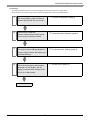
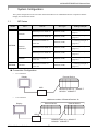
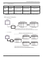
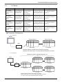
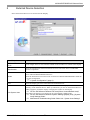
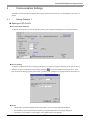
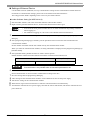
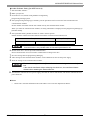
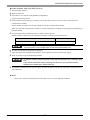
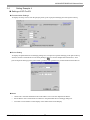
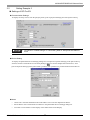
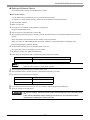
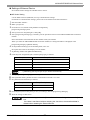
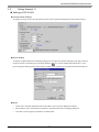
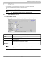
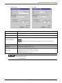
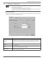
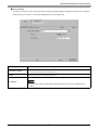
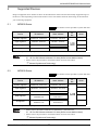
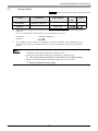
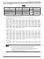
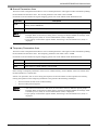
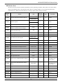
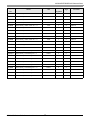
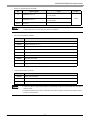
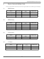
YASKAWA Electric Corporation
MP/INVERTER/SERVO
Ethernet Driver
1
System Configuration....................................................................................................... 3
2
External Device Selection ................................................................................................ 6
3
Communication Settings .................................................................................................. 7
4
Setup Items .................................................................................................................... 37
5
Supported Devices......................................................................................................... 42
6
Device Code and Address Code.................................................................................... 50
7
Error Messages.............................................................................................................. 51
1
MP/INVERTER/SERVO Ethernet Driver
Introduction
This manual describes how to connect the Display and the External Device (target PLC).
In this manual, the connection procedure will be described in the sections identified below:
1
System Configuration
This section lists the types of External
Devices and SIO that you can connect.
2
External Device Selection
Select a model (series) of the External
Device and its connection method.
3
Communication Settings
This section shows setting examples for
communicating between the Display and
the External Device.
4
Setup Items
This section describes communication
setup items on the Display. Set the
Display’s communication settings in GP
Pro-EX or in offline mode.
"2 External Device Selection" (page 6)
Operation
GP-Pro EX Device/PLC Connection Manual
"1 System Configuration" (page 3)
2
"3 Communication Settings" (page 7)
"4 Setup Items" (page 37)
MP/INVERTER/SERVO Ethernet Driver
1
System Configuration
The system configuration in the case when the External Device of YASKAWA Electric Corporation and the
Display are connected is shown.
1.1
MP Series
Series
CPU
Link I/F
SIO Type
Ethernet port on 218IF-01
Ethernet (UDP)
"3.1 Setting Example 1"
(page 7)
Ethernet port on 218IF-02
Ethernet (UDP)
"3.4 Setting Example 4"
(page 16)
Ethernet Connector on
CPU unit
Ethernet (UDP)
"3.2 Setting Example 2"
(page 10)
Ethernet port on 218IF-01
Ethernet (UDP)
"3.3 Setting Example 3"
(page 13)
Ethernet port on 218IF-02
Ethernet (UDP)
"3.4 Setting Example 4"
(page 16)
MP2400
Ethernet Connector on
CPU unit
Ethernet (UDP)
"3.2 Setting Example 2"
(page 10)
CPU201
Ethernet Connector on
CPU unit
Ethernet (UDP)
"3.9 Setting Example 9"
(page 31)
MP2300
MP2200
MP2000
MP2310
MP2300S
MP3000
Setting Example
Connection Configuration
•
1:1 Connection
Display
External Device
HUB
•
MP2000 (218IF-01) : 10BASE-T
MP3000 : 100BASE-T
1:n Connection
Maximum number of External Devices: 32
Display
External Device
External Device
HUB
MP2000 (218IF-01) : 10BASE-T
MP3000 : 100BASE-T
GP-Pro EX Device/PLC Connection Manual
3
MP/INVERTER/SERVO Ethernet Driver
1.2
Inverter Series
CPU*1
Series
Link I/F
Communication
Setting Example
V1000
CIMR-VA
A
V1000 Option
MECHATROLINK-II
(SI-T3/V)
Ethernet (UDP) and
MECHATROLINK-II
"3.10 Setting Example 10"
(page 33)
A1000
CIMR-A
A
A1000
MECHATROLINK-II
(SI-T3)
Ethernet (UDP) and
MECHATROLINK-II
"3.11 Setting Example 11"
(page 35)
*1
The
symbol in the inverter model name represents the maximum applicable motor capacity and other
specifications.
Connection Configuration
•
1:1 Connection
Display
External Device
External Device
HUB
MP series
Inverter series
Between Display and MP series: Ethernet connection
Between MP series and Inverter series: MECHATROLINK connection
•
1:n Connection
Maximum number of External Devices: 32
Display
External Device
External Device
Inverter series
Inverter series
Inverter series
Inverter series
External Device
HUB
MP series
Between Display and MP series: Ethernet connection
Between MP series and Inverter series: MECHATROLINK connection
Between Inverter series and Inverter series: MECHATROLINK connection
GP-Pro EX Device/PLC Connection Manual
4
MP/INVERTER/SERVO Ethernet Driver
Σ-V Series
1.3
Series
CPU
Σ-V Series
Rotary Motors
(M-II)
SGDV-
Σ-V Series
Linear Motors
(M-II)
SGDV-
Σ-V Series
Rotary Motors
(M-III)
SGDV-
Σ-V Series
Linear Motors
(M-III)
SGDV-
Link I/F
SIO Type
Setting Example
MECHATROLINK
11 Communications
Connectors
(CN6A/CN6B)
Ethernet (UDP) and
MECHATROLINK-II
"3.5 Setting Example 5"
(page 19)
MECHATROLINK
15 Communications
Connectors
(CN6A/CN6B)
Ethernet (UDP) and
MECHATROLINK-II
"3.6 Setting Example 6"
(page 22)
MECHATROLINK
21 Communications
Connectors
(CN6A/CN6B)
Ethernet (UDP) and
"3.7 Setting Example 7"
MECHATROLINK-III (page 25)
MECHATROLINK
25 Communications
Connectors
(CN6A/CN6B)
Ethernet (UDP) and
"3.8 Setting Example 8"
MECHATROLINK-III (page 28)
Connection Configuration
•
1:1 Connection
Display
External Device
External Device
HUB
MP series
Σ-V series
Between Display and MP series: Ethernet connection
Between MP series and Σ-V series: MECHATROLINK connection
•
1:n Connection
Maximum number of External Devices: 32
Display
External Device
External Device
Σ-V series
Σ-V series
External Device
External Device
Σ-V series
Σ-V series
External Device
HUB
MP series
Between Display and MP series: Ethernet connection
Between MP series and Σ-V series: MECHATROLINK connection
Σ-V series and Σ-V series: MECHATROLINK connection
GP-Pro EX Device/PLC Connection Manual
5
MP/INVERTER/SERVO Ethernet Driver
2
External Device Selection
Select the External Device to be connected to the Display.
Setup Items
Setup Description
Number of Devices/
PLCs
Use an integer from 1 to 4 to enter the number of Devices/PLCs to connect to the display.
Manufacturer
Select the manufacturer of the External Device to be connected. Select "YASKAWA
Electric Corporation".
Series
Select a model (series) of the External Device to be connected and connection method.
Select "MP/INVERTER/SERVO Ethernet".
Check the External Device which can be connected in "MP/INVERTER/SERVO Ethernet"
in system configuration.
"1 System Configuration" (page 3)
Port
Select the Display port to be connected to the External Device.
Use System Area
Check this option to synchronize the system data area of the Display and the device
(memory) of the External Device. When synchronized, you can use the External Device’s
ladder program to switch the display or display the window on the Display.
Cf. GP-Pro EX Reference Manual "LS Area (Direct Access Method Area)"
This feature can also be set in GP-Pro EX or in the Display's offline mode.
Cf. GP-Pro EX Reference Manual "System Settings [Display Unit] - [System
Area] Settings Guide"
Cf. Maintenance/Troubleshooting Guide "Main Unit - System Area Settings"
GP-Pro EX Device/PLC Connection Manual
6
MP/INVERTER/SERVO Ethernet Driver
3
Communication Settings
Examples of communication settings of the Display and the External Device, recommended by Pro-face, are
shown.
3.1
Setting Example 1
Settings of GP-Pro EX
Communication Settings
To display the setup screen, from the [Project] menu, point to [System Settings] and select [Device/PLC].
Device Setting
To display the [Individual Device Settings] dialog box, from [Device-Specific Settings] in the [Device/PLC]
window, select the External Device and click [Settings]
. To connect multiple External Devices, from
[Device-Specific Settings] in the [Device/PLC] window, click [Add Device] to add another External Device.
Notes
•
Check with a network administrator about IP address. Do not set the duplicate IP address.
•
Set IP address on the External Device address in the [Individual Device Settings] dialog box.
•
You need to set IP address on the Display in the offline mode of the Display.
GP-Pro EX Device/PLC Connection Manual
7
MP/INVERTER/SERVO Ethernet Driver
Settings of External Device
Use the ladder software (MPE720) to set up communication settings for the communication module 218IF-01.
For details on communication settings, please refer to the manual of the External Device.
The setup procedure differs depending on the version of your ladder software.
Ladder Software Setting (for MPE720 Ver.5)
1
2
Start the ladder software, and in the root folder make the order and PLC folders.
Right-click the generated External Device, and from the shortcut menu select Logon.
• In the shortcut menu, please confirm there is no check mark beside the [Online] command
before logging on.
• For methods on logging on, refer to the User's Manual of the External Device.
3
From the PLC folder, double-click the [Definition folder]’s [Module Configuration] to display the [Engineering
Manager].
4
In the [Engineering Manager]’s [Controller], use the pull-down menu to select the rack classification and
communication module.
Set the number associated with the slot number used by the communication module.
When you select the communication module, its setting information is displayed in the [Engineering Manager]’s
[Module details].
5
In the [Module details], double-click the No. field’s numeric portion.
Double-click the number associated with the slot number connected to the Ethernet unit.
Setup Items
Transmission parameter
Setup Description
This Station IP address
PLC IP address
• Please make the connection parameter blank.
Communication is not possible when a connection parameter is set.
6
Double-click "No.1" and set up serial communication.
Serial communication is used to transfer communication settings to the PLC.
7
8
9
10
11
Save the settings and exit [Engineering Manager].
After turning ON the communication module’s "INIT" DIP Switch, turn ON the power supply.
Transfer the settings to the communication module.
While online, logon to the External Device. Write the transferred data to FLASH memory.
Turn OFF the External Device’s power supply, turn OFF the "INIT" DIP Switch, and turn the External Device’s
power back ON.
GP-Pro EX Device/PLC Connection Manual
8
MP/INVERTER/SERVO Ethernet Driver
Ladder Software Setting (for MPE720 Ver.6)
1
2
3
Start the ladder software.
Make a project file.
From the tree view, double-click [Module Configuration].
[Engineering Manager] starts.
4
In the [Engineering Manager]’s [Controller], use the pull-down menu to select the rack classification and
communication module.
Set the number associated with the slot number used by the communication module.
When you select the communication module, its setting information is displayed in the [Engineering Manager]’s
[Module details].
5
In the [Module details], double-click the No. field’s numeric portion.
Double-click the number associated with the slot number connected to the Ethernet unit.
Setup Items
Transmission parameter
Setup Description
This Station IP address
PLC IP address
• Please make the connection parameter blank.
Communication is not possible when a connection parameter is set.
6
Double-click "No.1" and set up serial communication.
Serial communication is used to transfer communication settings to the PLC.
7
8
9
Save the settings and exit [Engineering Manager].
After turning ON the communication module’s "INIT" DIP Switch, turn ON the power supply.
Write the settings to the communication module.
• To write the settings, select the [Save to flash after transferring to the controller] check
box.
If the data is transferred without selecting the check box, the transferred data is
deleted when restarting the External Device.
10
Turn OFF the External Device’s power supply, turn OFF the "INIT" DIP Switch, and turn the External Device’s
power back ON.
Notes
•
Check with a network administrator about IP address. Do not set the duplicate IP address.
GP-Pro EX Device/PLC Connection Manual
9
MP/INVERTER/SERVO Ethernet Driver
3.2
Setting Example 2
Settings of GP-Pro EX
Communication Settings
To display the setup screen, from the [Project] menu, point to [System Settings] and select [Device/PLC].
Device Setting
To display the [Individual Device Settings] dialog box, from [Device-Specific Settings] in the [Device/PLC]
window, select the External Device and click [Settings]
. To connect multiple External Devices, from
[Device-Specific Settings] in the [Device/PLC] window, click [Add Device] to add another External Device.
Notes
•
Check with a network administrator about IP address. Do not set the duplicate IP address.
•
Set IP address on the External Device address in the [Individual Device Settings] dialog box.
•
You need to set IP address on the Display in the offline mode of the Display.
GP-Pro EX Device/PLC Connection Manual
10
MP/INVERTER/SERVO Ethernet Driver
Settings of External Device
Use the ladder software (MPE720) to set up communication settings for the communication module CPU unit.
For details on communication settings, please refer to the manual of the External Device.
The setup procedure differs depending on the version of your ladder software.
Ladder Software Setting (for MPE720 Ver.5)
1
2
Start the ladder software, and in the root folder make the order and PLC folders.
Right-click the generated External Device, and from the shortcut menu select Logon.
• In the shortcut menu, please confirm there is no check mark beside the [Online] command
before logging on.
• For methods on logging on, refer to the User's Manual of the External Device.
3
From the PLC folder, double-click the [Definition folder]’s [Module Configuration] to display the [Engineering
Manager].
4
In the [Engineering Manager]’s [Controller], use the pull-down menu to select the rack classification and
communication module.
Set the number associated with the slot number used by the communication module.
When you select the communication module, its setting information is displayed in the [Engineering Manager]’s
[Module details].
5
In the [Module details], double-click the No. field’s numeric portion.
Double-click the number associated with the slot number connected to the Ethernet unit.
Setup Items
Transmission parameter
Setup Description
This Station IP address
PLC IP address
• Please make the connection parameter blank.
Communication is not possible when a connection parameter is set.
6
7
8
9
10
Save the settings and exit [Engineering Manager].
After turning ON the communication module’s "INIT" DIP Switch, turn ON the power supply.
Transfer the settings to the communication module.
While online, logon to the External Device. Write the transferred data to FLASH memory.
Turn OFF the External Device’s power supply, turn OFF the "INIT" DIP Switch, and turn the External Device’s
power back ON.
GP-Pro EX Device/PLC Connection Manual
11
MP/INVERTER/SERVO Ethernet Driver
Ladder Software Setting (for MPE720 Ver.6)
1
2
3
Start the ladder software.
Make a project file.
From the tree view, double-click [Module Configuration].
[Engineering Manager] starts.
4
In the [Engineering Manager]’s [Controller], use the pull-down menu to select the rack classification and
communication module.
Set the number associated with the slot number used by the communication module.
When you select the communication module, its setting information is displayed in the [Engineering Manager]’s
[Module details].
5
In the [Module details], double-click the No. field’s numeric portion.
Double-click the number associated with the slot number connected to the Ethernet unit.
Setup Items
Transmission parameter
Setup Description
This Station IP address
PLC IP address
• Please make the connection parameter blank.
Communication is not possible when a connection parameter is set.
6
7
8
Save the settings and exit [Engineering Manager].
After turning ON the communication module’s "INIT" DIP Switch, turn ON the power supply.
Write the settings to the communication module.
• To write the settings, select the [Save to flash after transferring to the controller] check
box.
If the data is transferred without selecting the check box, the transferred data is
deleted when restarting the External Device.
9
Turn OFF the External Device’s power supply, turn OFF the "INIT" DIP Switch, and turn the External Device’s
power back ON.
Notes
•
Check with a network administrator about IP address. Do not set the duplicate IP address.
GP-Pro EX Device/PLC Connection Manual
12
MP/INVERTER/SERVO Ethernet Driver
3.3
Setting Example 3
Settings of GP-Pro EX
Communication Settings
To display the setup screen, from the [Project] menu, point to [System Settings] and select [Device/PLC].
Device Setting
To display the [Individual Device Settings] dialog box, from [Device-Specific Settings] in the [Device/PLC]
window, select the External Device and click [Settings]
. To connect multiple External Devices, from
[Device-Specific Settings] in the [Device/PLC] window, click [Add Device] to add another External Device.
Notes
•
Check with a network administrator about IP address. Do not set the duplicate IP address.
•
Set IP address on the External Device address in the [Individual Device Settings] dialog box.
•
You need to set IP address on the Display in the offline mode of the Display.
GP-Pro EX Device/PLC Connection Manual
13
MP/INVERTER/SERVO Ethernet Driver
Settings of External Device
Use the ladder software (MPE720) to set up communication settings for the communication module 218IF-01.
For details on communication settings, please refer to the manual of the External Device.
The setup procedure differs depending on the version of your ladder software.
Ladder Software Setting (for MPE720 Ver.5)
1
2
Start the ladder software, and in the root folder make the order and PLC folders.
Right-click the generated External Device, and from the shortcut menu select Logon.
• In the shortcut menu, please confirm there is no check mark beside the [Online] command
before logging on.
• For methods on logging on, refer to the User's Manual of the External Device.
3
From the PLC folder, double-click the [Definition folder]’s [Module Configuration] to display the [Engineering
Manager].
4
In the [Engineering Manager]’s [Controller], use the pull-down menu to select the rack classification and
communication module.
Set the number associated with the slot number used by the communication module.
When you select the communication module, its setting information is displayed in the [Engineering Manager]’s
[Module details].
5
In the [Module details], double-click the No. field’s numeric portion.
Double-click the number associated with the slot number connected to the Ethernet unit.
Setup Items
Transmission parameter
Setup Description
This Station IP address
PLC IP address
• Please make the connection parameter blank.
Communication is not possible when a connection parameter is set.
6
7
8
9
10
Save the settings and exit [Engineering Manager].
After turning ON the communication module’s "INIT" DIP Switch, turn ON the power supply.
Transfer the settings to the communication module.
While online, logon to the External Device. Write the transferred data to FLASH memory.
Turn OFF the External Device’s power supply, turn OFF the "INIT" DIP Switch, and turn the External Device’s
power back ON.
GP-Pro EX Device/PLC Connection Manual
14
MP/INVERTER/SERVO Ethernet Driver
Ladder Software Setting (for MPE720 Ver.6)
1
2
3
Start the ladder software.
Make a project file.
From the tree view, double-click [Module Configuration].
[Engineering Manager] starts.
4
In the [Engineering Manager]’s [Controller], use the pull-down menu to select the rack classification and
communication module.
Set the number associated with the slot number used by the communication module.
When you select the communication module, its setting information is displayed in the [Engineering Manager]’s
[Module details].
5
In the [Module details], double-click the No. field’s numeric portion.
Double-click the number associated with the slot number connected to the Ethernet unit.
Setup Items
Transmission parameter
Setup Description
This Station IP address
PLC IP address
• Please make the connection parameter blank.
Communication is not possible when a connection parameter is set.
6
7
8
Save the settings and exit [Engineering Manager].
After turning ON the communication module’s "INIT" DIP Switch, turn ON the power supply.
Write the settings to the communication module.
• To write the settings, select the [Save to flash after transferring to the controller] check
box.
If the data is transferred without selecting the check box, the transferred data is
deleted when restarting the External Device.
9
Turn OFF the External Device’s power supply, turn OFF the "INIT" DIP Switch, and turn the External Device’s
power back ON.
Notes
•
Check with a network administrator about IP address. Do not set the duplicate IP address.
GP-Pro EX Device/PLC Connection Manual
15
MP/INVERTER/SERVO Ethernet Driver
3.4
Setting Example 4
Settings of GP-Pro EX
Communication Settings
To display the setup screen, from the [Project] menu, point to [System Settings] and select [Device/PLC].
Device Setting
To display the [Individual Device Settings] dialog box, from [Device-Specific Settings] in the [Device/PLC]
window, select the External Device and click [Settings]
. To connect multiple External Devices, from
[Device-Specific Settings] in the [Device/PLC] window, click [Add Device] to add another External Device.
Notes
•
Check with a network administrator about IP address. Do not set the duplicate IP address.
•
Set IP address on the External Device address in the [Individual Device Settings] dialog box.
•
You need to set IP address on the Display in the offline mode of the Display.
GP-Pro EX Device/PLC Connection Manual
16
MP/INVERTER/SERVO Ethernet Driver
Settings of External Device
Use the ladder software (MPE720) to set up communication settings for the communication module 218IF-01.
For details on communication settings, please refer to the manual of the External Device.
The setup procedure differs depending on the version of your ladder software.
Ladder Software Setting (for MPE720 Ver.5)
1
2
Start the ladder software, and in the root folder make the order and PLC folders.
Right-click the generated External Device, and from the shortcut menu select Logon.
• In the shortcut menu, please confirm there is no check mark beside the [Online] command
before logging on.
• For methods on logging on, refer to the User's Manual of the External Device.
3
From the PLC folder, double-click the [Definition folder]’s [Module Configuration] to display the [Engineering
Manager].
4
In the [Engineering Manager]’s [Controller], use the pull-down menu to select the rack classification and
communication module.
Set the number associated with the slot number used by the communication module.
When you select the communication module, its setting information is displayed in the [Engineering Manager]’s
[Module details].
5
In the [Module details], double-click the No. field’s numeric portion.
Double-click the number associated with the slot number connected to the Ethernet unit.
Setup Items
Transmission parameter
Setup Description
This Station IP address
PLC IP address
• Please make the connection parameter blank.
Communication is not possible when a connection parameter is set.
6
7
8
9
10
Save the settings and exit [Engineering Manager].
After turning ON the communication module’s "INIT" DIP Switch, turn ON the power supply.
Transfer the settings to the communication module.
While online, logon to the External Device. Write the transferred data to FLASH memory.
Turn OFF the External Device’s power supply, turn OFF the "INIT" DIP Switch, and turn the External Device’s
power back ON.
GP-Pro EX Device/PLC Connection Manual
17
MP/INVERTER/SERVO Ethernet Driver
Ladder Software Setting (for MPE720 Ver.6)
1
2
3
Start the ladder software.
Make a project file.
From the tree view, double-click [Module Configuration].
[Engineering Manager] starts.
4
In the [Engineering Manager]’s [Controller], use the pull-down menu to select the rack classification and
communication module.
Set the number associated with the slot number used by the communication module.
When you select the communication module, its setting information is displayed in the [Engineering Manager]’s
[Module details].
5
In the in [Module details], double-click the No. field’s numeric portion.
Double-click the number associated with the slot number connected to the Ethernet unit.
Setup Items
Transmission parameter
Setup Description
This Station IP address
PLC IP address
• Please make the connection parameter blank.
Communication is not possible when a connection parameter is set.
6
7
8
Save the settings and exit [Engineering Manager].
After turning ON the communication module’s "INIT" DIP Switch, turn ON the power supply.
Write the settings to the communication module.
• To write the settings, select the [Save to flash after transferring to the controller] check
box.
If the data is transferred without selecting the check box, the transferred data is
deleted when restarting the External Device.
9
Turn OFF the External Device’s power supply, turn OFF the "INIT" DIP Switch, and turn the External Device’s
power back ON.
Notes
•
Check with a network administrator about IP address. Do not set the duplicate IP address.
GP-Pro EX Device/PLC Connection Manual
18
MP/INVERTER/SERVO Ethernet Driver
3.5
Setting Example 5
Settings of GP-Pro EX
Communication Settings
To display the setup screen, from the [Project] menu, point to [System Settings] and select [Device/PLC].
• To connect Σ-V Series using a 1:n connection, [Wait To Send] must be 100ms or
more.
Device Setting
To display the [Individual Device Settings] dialog box, from [Device-Specific Settings] in the [Device/PLC]
window, select the External Device and click [Settings]
. To connect multiple External Devices, from
[Device-Specific Settings] in the [Device/PLC] window, click [Add Device] to add another External Device.
Notes
•
Check with a network administrator about IP address. Do not set the duplicate IP address.
•
Set IP address on the External Device address in the [Individual Device Settings] dialog box.
•
You need to set IP address on the Display in the offline mode of the Display.
GP-Pro EX Device/PLC Connection Manual
19
MP/INVERTER/SERVO Ethernet Driver
Settings of External Device
Set communication settings for both MP and Σ-V Series.
MP Series Setting
Use the ladder software (MPE720) to set up communication settings.
For details on communication settings, please refer to the manual of the External Device.
1
2
3
Start the ladder software.
Make a project file.
From the tree view, double-click [Module Configuration].
[Engineering Manager] starts.
4
5
In the [Create new file] dialog box, click [OK].
In the [Engineering Manager]’s [Controller], use the pull-down menu to select MECHATROLINK connection
module.
Select the number associated with the slot number used by the module.
When you select the MECHATROLINK connection module, its setting information is displayed in the
[Engineering Manger]’s [Module details].
6
In the [module Details]’s [Circuit Number] field, enter "01".
Set up the same value as the Display’s circuit number.
7
8
In [Details], double-click [MECHATROLINK].
Click the [Link Assignments] tab, and then set [ST#]’s [01] field as follows.
Setup Items
Setup Description
Select the type of Σ-V Series you are using.
TYPE
• [ST#] is defined based on the Σ-V Series station address.
When the station address is 41H, define "ST#01".
9
10
11
In the [Engineering Manager]’s [Controller], select CPU.
In the [Module details], double-click the communication module’s No. field.
Set [Transmission Parameters] as follows.
Setup Items
12
13
Setup Description
IP Address
192.168.0.1
Subnet Mask
255.255.255.0
From the [File] menu select [Save] to save your settings, and exit [Engineering Manager].
Write the settings to the MP Series.
• To write the settings, select the [Save to flash after transferring to the controller] check
box.
If the data is transferred without selecting the check box, the transferred data is
deleted when restarting the External Device.
GP-Pro EX Device/PLC Connection Manual
20
MP/INVERTER/SERVO Ethernet Driver
Σ-V Series Setting
Set up communication settings with the DIP Switch (SW2) and the rotary switch (SW1). For example, when the
SW2-3 is OFF and SW1 is 1, the station address is 41H.
For details on communication settings, please refer to the manual for the External Device.
•
•
DIP Switch (SW2) Setting
DIP Switch
Settings
Setup Description
1
ON
2
Optional
3
OFF
Define the station address in combination with the rotary switch (SW1).
ON: Tenth’s position of station address is 0x5
OFF: Tenth’s position of station address is 0x4
4
OFF
Always OFF
Communication speed: 10Mbps (MECHATROLINK-II)
Data transfer size.
ON: 32-byte data transfer
OFF: 17-byte data transfer
Rotary Switch (SW1) Setting
Set the station address in combination with the DIP Switch (SW2), number 3.
Rotary Switch
Settings
SW1
1
Setup Description
Ones place of the station address
Notes
•
Check with a network administrator about IP address. Do not set the duplicate IP address.
GP-Pro EX Device/PLC Connection Manual
21
MP/INVERTER/SERVO Ethernet Driver
3.6
Setting Example 6
Settings of GP-Pro EX
Communication Settings
To display the setup screen, from the [Project] menu, point to [System Settings] and select [Device/PLC].
• To connect Σ-V Series using a 1:n connection, [Wait To Send] must be 100ms or
more.
Device Setting
To display the [Individual Device Settings] dialog box, from [Device-Specific Settings] in the [Device/PLC]
window, select the External Device and click [Settings]
. To connect multiple External Devices, from
[Device-Specific Settings] in the [Device/PLC] window, click [Add Device] to add another External Device.
Notes
•
Check with a network administrator about IP address. Do not set the duplicate IP address.
•
Set IP address on the External Device address in the [Individual Device Settings] dialog box.
•
You need to set IP address on the Display in the offline mode of the Display.
GP-Pro EX Device/PLC Connection Manual
22
MP/INVERTER/SERVO Ethernet Driver
Settings of External Device
Set communication settings for both MP and Σ-V Series.
MP Series Setting
Use the ladder software (MPE720) to set up communication settings.
For details on communication settings, please refer to the manual of the External Device.
1
2
3
Start the ladder software.
Make a project file.
From the tree view, double-click [Module Configuration].
[Engineering Manager] starts.
4
5
In the [Create new file] dialog box, click [OK].
In the [Engineering Manager]’s [Controller], use the pull-down menu to select MECHATROLINK connection
module.
Select the number associated with the slot number used by the module.
When you select the MECHATROLINK connection module, its setting information is displayed in the
[Engineering Manger]’s [Module details].
6
In the [module Details]’s [Circuit Number] field, enter "01".
Set up the same value as the Display’s circuit number.
7
8
In [Details], double-click [MECHATROLINK].
Click the [Link Assignments] tab, and then set [ST#]’s [01] field as follows.
Setup Items
Setup Description
Select the type of Σ-V Series you are using.
TYPE
• [ST#] is defined based on the Σ-V Series station address.
When the station address is 41H, define "ST#01".
9
10
11
In the [Engineering Manager]’s [Controller], select CPU.
In the [Module details], double-click the communication module’s No. field.
Set [Transmission Parameters] as follows.
Setup Items
12
13
Setup Description
IP Address
192.168.0.1
Subnet Mask
255.255.255.0
From the [File] menu select [Save] to save your settings, and exit [Engineering Manager].
Write the settings to the MP Series.
• To write the settings, select the [Save to flash after transferring to the controller] check
box.
If the data is transferred without selecting the check box, the transferred data is
deleted when restarting the External Device.
GP-Pro EX Device/PLC Connection Manual
23
MP/INVERTER/SERVO Ethernet Driver
Σ-V Series Setting
Set up communication settings with the DIP Switch (SW2) and the rotary switch (SW1). For example, when the
SW2-3 is OFF and SW1 is 1, the station address is 41H.
For details on communication settings, please refer to the manual for the External Device.
•
•
DIP Switch (SW2) Setting
DIP Switch
Settings
Setup Description
1
ON
2
Optional
3
OFF
Define the station address in combination with the rotary switch (SW1).
ON: Tenth’s position of station address is 0x5
OFF: Tenth’s position of station address is 0x4
4
OFF
Always OFF
Communication speed: 10Mbps (MECHATROLINK-II)
Data transfer size.
ON: 32-byte data transfer
OFF: 17-byte data transfer
Rotary Switch (SW1) Setting
Set the station address in combination with the DIP Switch (SW2), number 3.
Rotary Switch
Settings
SW1
1
Setup Description
Ones place of the station address
Notes
•
Check with a network administrator about IP address. Do not set the duplicate IP address.
GP-Pro EX Device/PLC Connection Manual
24
MP/INVERTER/SERVO Ethernet Driver
3.7
Setting Example 7
Settings of GP-Pro EX
Communication Settings
To display the setup screen, from the [Project] menu, point to [System Settings] and select [Device/PLC].
• To connect Σ-V Series using a 1:n connection, [Wait To Send] must be 100ms or
more.
Device Setting
To display the [Individual Device Settings] dialog box, from [Device-Specific Settings] in the [Device/PLC]
window, select the External Device and click [Settings]
. To connect multiple External Devices, from
[Device-Specific Settings] in the [Device/PLC] window, click [Add Device] to add another External Device.
Notes
•
Check with a network administrator about IP address. Do not set the duplicate IP address.
•
Set IP address on the External Device address in the [Individual Device Settings] dialog box.
•
You need to set IP address on the Display in the offline mode of the Display.
GP-Pro EX Device/PLC Connection Manual
25
MP/INVERTER/SERVO Ethernet Driver
Settings of External Device
Set communication settings for both MP and Σ-V Series.
MP Series Setting
Use the ladder software (MPE720) to set up communication settings.
For details on communication settings, please refer to the manual of the External Device.
1
2
3
Start the ladder software.
Make a project file.
From the tree view, double-click [Module Configuration].
[Engineering Manager] starts.
4
5
In the [Create new file] dialog box, click [OK].
In the [Engineering Manager]’s [Controller], use the pull-down menu to select MECHATROLINK connection
module.
Select the number associated with the slot number used by the module.
When you select the MECHATROLINK connection module, its setting information is displayed in the
[Engineering Manger]’s [Module details].
6
In the [module Details]’s [Circuit Number] field, enter "01".
Set up the same value as the Display’s circuit number.
7
8
In [Details], double-click [MECHATROLINK].
Click the [Link Assignments] tab, and then [ST#]’s [01] as follows.
Setup Items
Setup Description
ADR
03H
ExADR
00
VENDOR
Yaskawa Electric co.
DEVICE
Σ-V Series type
• [PROFILE], [BYTE] and [SCAN] are defined automatically.
9
10
11
In the [Engineering Manager]’s [Controller], select CPU.
In the [Module details], double-click the communication module’s No. field.
Set [Transmission Parameters] as follows.
Setup Items
12
13
Setup Description
IP Address
192.168.0.1
Subnet Mask
255.255.255.0
From the [File] menu select [Save] to save your settings, and exit [Engineering Manager].
Write the settings to MP Series.
• To write the settings, select the [Save to flash after transferring to the controller] check
box.
If the data is transferred without selecting the check box, the transferred data is
deleted when restarting the External Device.
GP-Pro EX Device/PLC Connection Manual
26
MP/INVERTER/SERVO Ethernet Driver
Σ-V Series Setting
Set up communication settings with rotary switches (S1 and S2).
For details on communication settings, please refer to the manual of the External Device.
Rotary Switch
Settings
S1 (x16)
0
S2 (x1)
3
Setup Description
Station address
Notes
•
Check with a network administrator about IP address. Do not set the duplicate IP address.
GP-Pro EX Device/PLC Connection Manual
27
MP/INVERTER/SERVO Ethernet Driver
3.8
Setting Example 8
Settings of GP-Pro EX
Communication Settings
To display the setup screen, from the [Project] menu, point to [System Settings] and select [Device/PLC].
• To connect Σ-V Series using a 1:n connection, [Wait To Send] must be 100ms or
more.
Device Setting
To display the [Individual Device Settings] dialog box, from [Device-Specific Settings] in the [Device/PLC]
window, select the External Device and click [Settings]
. To connect multiple External Devices, from
[Device-Specific Settings] in the [Device/PLC] window, click [Add Device] to add another External Device.
Notes
•
Check with a network administrator about IP address. Do not set the duplicate IP address.
•
Set IP address on the External Device address in the [Individual Device Settings] dialog box.
•
You need to set IP address on the Display in the offline mode of the Display.
GP-Pro EX Device/PLC Connection Manual
28
MP/INVERTER/SERVO Ethernet Driver
Settings of External Device
Set communication settings for both MP and Σ-V Series.
MP Series Setting
Use the ladder software (MPE720) to set up communication settings.
For details on communication settings, please refer to the manual of the External Device.
1
2
3
Start the ladder software.
Make a project file.
From the tree view, double-click [Module Configuration].
[Engineering Manager] starts.
4
5
In the [Create new file] dialog box, click [OK].
In the [Engineering Manager]’s [Controller], use the pull-down menu to select MECHATROLINK connection
module.
Select the number associated with the slot number used by the module.
When you select the MECHATROLINK connection module, its setting information is displayed in the
[Engineering Manger]’s [Module details].
6
In the [module Details]’s [Circuit Number] field, enter "01".
Set up the same value as the Display’s circuit number.
7
8
In [Details], double-click [MECHATROLINK].
Click the [Link Assignments] tab, and then [ST#]’s [01] as follows.
Setup Items
Setup Description
ADR
03H
ExADR
00
VENDOR
Yaskawa Electric co.
DEVICE
Σ-V Series type
• [PROFILE], [BYTE] and [SCAN] are defined automatically.
9
10
11
In the [Engineering Manager]’s [Controller], select CPU.
In the [Module details], double-click the communication module’s No. field.
Set [Transmission Parameters] as follows.
Setup Items
12
13
Setup Description
IP Address
192.168.0.1
Subnet Mask
255.255.255.0
From the [File] menu select [Save] to save your settings, and exit [Engineering Manager].
Write the settings to MP Series.
• To write the settings, select the [Save to flash after transferring to the controller] check
box.
If the data is transferred without selecting the check box, the transferred data is
deleted when restarting the External Device.
GP-Pro EX Device/PLC Connection Manual
29
MP/INVERTER/SERVO Ethernet Driver
Σ-V Series Setting
Set up communication settings with rotary switches (S1 and S2).
For details on communication settings, please refer to the manual of the External Device.
Rotary Switch
Settings
S1 (x16)
0
S2 (x1)
3
Setup Description
Station address
Notes
•
Check with a network administrator about IP address. Do not set the duplicate IP address.
GP-Pro EX Device/PLC Connection Manual
30
MP/INVERTER/SERVO Ethernet Driver
3.9
Setting Example 9
Settings of GP-Pro EX
Communication Settings
To display the setup screen, from the [Project] menu, point to [System Settings] and select [Device/PLC].
Device Setting
To display the [Individual Device Settings] dialog box, from [Device-Specific Settings] in the [Device/PLC]
window, select the External Device and click [Settings]
. To connect multiple External Devices, from
[Device-Specific Settings] in the [Device/PLC] window, click [Add Device] to add another External Device.
Notes
•
Check with a network administrator about IP address. Do not set the duplicate IP address.
•
Set IP address on the External Device address in the [Individual Device Settings] dialog box.
•
You need to set the Display's IP address in its offline mode.
GP-Pro EX Device/PLC Connection Manual
31
MP/INVERTER/SERVO Ethernet Driver
Settings of External Device
Use the ladder software (MP720 Ver.7) to set up communication settings.
For details on communication settings, please refer to the manual of the External Device.
1
2
3
4
5
6
Start the ladder software.
Make a project file.
Click [Module Configuration] to start [MC-Configurator].
Double-click [218IFD] on the CPU you want to use.
Click the [Transmission Parameters] tab.
In the [Transmission Parameters], set the [IP Address] and [Subnet Mask].
Setup Items
Setup Description
IP Address
Subnet Mask
7
8
192.168.0.1
255.255.255.0
Write the settings to the External Device.
Turn ON the External Device again.
Notes
•
Check with a network administrator about IP address. Do not set the duplicate IP address.
GP-Pro EX Device/PLC Connection Manual
32
MP/INVERTER/SERVO Ethernet Driver
3.10
Setting Example 10
Settings of GP-Pro EX
Communication Settings
To display the setup screen, from the [Project] menu, point to [System Settings] and select [Device/PLC].
Device Setting
To display the [Individual Device Settings] dialog box, from [Device-Specific Settings] in the [Device/PLC]
window, select the External Device and click [Settings]
. To connect multiple External Devices, from
[Device-Specific Settings] in the [Device/PLC] window, click [Add Device] to add another External Device.
Notes
•
Check with a network administrator about IP address. Do not set the duplicate IP address.
•
Set IP address on the External Device address in the [Individual Device Settings] dialog box.
•
You need to set the Display's IP address in offline mode.
GP-Pro EX Device/PLC Connection Manual
33
MP/INVERTER/SERVO Ethernet Driver
Settings of External Device
For details on communication settings, please refer to the manual of the External Device.
Setup Procedure
1
2
3
Press UP to display the Parameter Setting Mode screen. Press ENTER to change to Set Up Mode.
Press UP to display setup items. Press ENTER key to change to setup screen.
Press UP or RESET to select the setup value. Press ENTER to set up a description.
Setup Description
Setup Items
Setup value
Description
b1-02*1
3
Run Command Selection (Option Card)
F60-20
21
MECHATROLINK station address
F60-22
0
MECHATROLINK link rate (10Mbps)
*1
Set b1-01 to 3 when you set the frequency via MECHATROLINK.
GP-Pro EX Device/PLC Connection Manual
34
MP/INVERTER/SERVO Ethernet Driver
3.11
Setting Example 11
Settings of GP-Pro EX
Communication Settings
To display the setup screen, from the [Project] menu, point to [System Settings] and select [Device/PLC].
Device Setting
To display the [Individual Device Settings] dialog box, from [Device-Specific Settings] in the [Device/PLC]
window, select the External Device and click [Settings]
. To connect multiple External Devices, from
[Device-Specific Settings] in the [Device/PLC] window, click [Add Device] to add another External Device.
Notes
•
Check with a network administrator about IP address. Do not set the duplicate IP address.
•
Set IP address on the External Device address in the [Individual Device Settings] dialog box.
•
You need to set the Display's IP address in offline mode.
GP-Pro EX Device/PLC Connection Manual
35
MP/INVERTER/SERVO Ethernet Driver
Settings of External Device
For details on communication settings, please refer to the manual of the External Device.
Setup Procedure
1
2
3
Press UP to display the Parameter Setting Mode screen. Press ENTER to change to Set Up Mode.
Press UP to display setup items. Press ENTER key to change to setup screen.
Press UP or RESET to select the setup value. Press ENTER to set up a description.
Setup Description
Setup Items
Setup value
Description
b1-02*1
3
Run Command Selection (Option Card)
F60-20
21
MECHATROLINK station address
F60-22
0
MECHATROLINK link rate (10Mbps)
*1
Set b1-01 to 3 when you set the frequency via MECHATROLINK.
GP-Pro EX Device/PLC Connection Manual
36
MP/INVERTER/SERVO Ethernet Driver
4
Setup Items
Set up the Display’s communication settings in GP Pro-EX or in the Display’s offline mode.
The setting of each parameter must match that of the External Device.
"3 Communication Settings" (page 7)
• Set the Display’s IP address in offline mode.
Cf.
4.1
Maintenance/Troubleshooting Guide "Ethernet Settings"
Setup Items in GP-Pro EX
Communication Settings
To display the setup screen, from the [Project] menu, point to [System Settings] and select [Device/PLC].
Setup Items
Setup Description
Port No.
Enter a port number of the External Device, using 1024 to 65535. Check into [Auto], and a
port number is set automatically.
Timeout
Use an integer from 1 to 127 to enter the time (s) for which Display waits for the response
from External Device.
Retry
In case of no response from the External Device, use an integer from 0 to 255 to enter how
many times the Display retransmits the command.
Wait To Send
Use an integer from 0 to 255 to enter standby time (ms) for the Display from receiving
packets to transmitting next commands.
• Refer to the GP-Pro EX Reference Manual for Indirect Device.
Cf. GP-Pro EX Reference Manual "Changing the Device/PLC at Runtime (Indirect
Device)"
GP-Pro EX Device/PLC Connection Manual
37
MP/INVERTER/SERVO Ethernet Driver
Device Setting
To display the [Individual Device Settings] dialog box, from [Device-Specific Settings] in the [Device/PLC]
window, select the External Device and click [Settings]
. To connect multiple External Devices, from
[Device-Specific Settings] in the [Device/PLC] window, click [Add Device] to add another External Device.
MP2000/MP3000 Series
Setup Items
Product
Setup Description
Select the product name of the External Device.
Set IP address of the External Device.
IP Address
• Check with a network administrator about IP address. Do not set the duplicate IP
address.
GP-Pro EX Device/PLC Connection Manual
38
MP/INVERTER/SERVO Ethernet Driver
Σ-V Series
Inverter Series
Setup Items
Setup Description
Product
Select the product name of the External Device.
Series
Select the series of the External Device.
Set IP address of the relay device (MP Series).
Relay IP Address
• Check with a network administrator about IP address. Do not set the duplicate IP
address.
Device Type
Display the device type.
Circuit No.
Enter the circuit number, from 1 to 16.
Station No.
Inverter Series: Enter the station number, from 1 to 255.
Σ-V Series: Enter the station number as follows.
MECHATROLINK-II: "65 to 79" and "80 to 95"
MECHATROLINK-III: "3 to 239"
• When communicating with the Σ-V Series, the first three octets in the subnet mask
should be set to 255.
e.g.: 255.255.255.0
GP-Pro EX Device/PLC Connection Manual
39
MP/INVERTER/SERVO Ethernet Driver
4.2
Setup Items in Offline Mode
• Please refer to Maintenance/Troubleshooting Guide for more information on how to enter
offline mode or about operation.
Cf. Maintenance/Troubleshooting Guide "Offline Mode"
• The number of the setup items to be displayed for 1 page in the offline mode depends on the
Display in use. Please refer to the Reference manual for details.
Communication Settings
To display the setting screen, touch [Device/PLC Settings] from [Peripheral Settings] in offline mode. Touch the
External Device you want to set from the displayed list.
Setup Items
Setup Description
Port No.
Enter a port number of the Display.
Select either of "Fixed" "Auto". Enter a port number of the Display with "1024-65535",
when select "Fixed". Assign automatically without affecting the input value, when select
"Auto".
Timeout
Use an integer from 1 to 127 to enter the time (s) for which Display waits for the response
from External Device.
Retry
In case of no response from the External Device, use an integer from 0 to 255 to enter how
many times the Display retransmits the command.
Wait To Send
Use an integer from 0 to 255 to enter standby time (ms) for the Display from receiving
packets to transmitting next commands.
GP-Pro EX Device/PLC Connection Manual
40
MP/INVERTER/SERVO Ethernet Driver
Device Setting
To display the setting screen, touch [Device/PLC Settings] from [Peripheral Settings] in offline mode. Touch the
External Device you want to set from the displayed list, and touch [Device].
Setup Items
Setup Description
Device/PLC Name
Select the External Device for device setting. Device name is a title of the External Device
set with GP-Pro EX. (Initial value [PLC1])
Series
Display the series of the External Device.
Set IP addresses used by the External Device or relay device (MP Series).
IP Address
• Check with a network administrator about IP address. Do not set the duplicate IP
address.
GP-Pro EX Device/PLC Connection Manual
41
MP/INVERTER/SERVO Ethernet Driver
5
Supported Devices
Range of supported device address is shown in the table below. Please note that the actually supported range of
the devices varies depending on the External Device to be used. Please check the actual range in the manual of
your connecting equipment.
5.1
MP2000 Series
This address can be specified as system data area.
*1
32
bits
Device
Bit Address
Word Address
Notes
System registers
SB000000 - SB08191F
SW00000 - SW08191
Input registers
IB00000 - IBFFFFF
IW0000 - IWFFFF
*1
Output registers
OB00000 - OBFFFFF
OW0000 - OWFFFF
*1
Data registers
MB000000 - MB65534F
MW00000 - MW65534
As for Input and Output registers, device 0x9000-0xFFFF cannot be written.
• Please refer to the GP-Pro EX Reference Manual for system data area.
Cf. GP-Pro EX Reference Manual "LS Area (Direct Access Method Area)"
• Please refer to the precautions on manual notation for icons in the table.
"Manual Symbols and Terminology"
5.2
MP3000 Series
This address can be specified as system data area.
*1
32
bits
Device
Bit Address
Word Address
Notes
System registers
SB000000 - SB65534F
SW00000 - SW65534
Input registers
IB000000 - IB17FFFF
IW00000 - IW17FFF
*1
Output registers
OB000000 - OB17FFFF
OW00000 - OW17FFF
*1
Data registers
MB00000000 MB1048575F
MW0000000 MW1048575
G registers
GB000000000 GB02097151F
GW00000000 GW02097151
As for Input and Output registers, device 0x9000-0xFFFF cannot be written.
• Please refer to the GP-Pro EX Reference Manual for system data area.
Cf. GP-Pro EX Reference Manual "LS Area (Direct Access Method Area)"
• Please refer to the precautions on manual notation for icons in the table.
"Manual Symbols and Terminology"
GP-Pro EX Device/PLC Connection Manual
42
MP/INVERTER/SERVO Ethernet Driver
5.3
Inverter Series
This address can be specified as system data area.
*1
Device
Bit Address
Word Address
32
bits
Bit registers*1
BR0000.0 - BR195C.F
-
-
Registers*1
-
0000~195C
Notes
*2
*2
In the Inverter, bit registers and registers use the same device. Bit registers are used only for bit
addresses.
The access method when specifying bits varies depending on the device.
Bit registers.................................BR0000.0 - BR195C.F
Registers .....................................
*2
The available register numbers and available read/write operations differ depending on the
External Device model. For further information, refer to the instruction manual for your External
Device.
• You can only set the Read Area Size for the system area in the External Device. Please refer
to the GP-Pro EX Reference Manual for Read Area Size.
• Please refer to the GP-Pro EX Reference Manual for system data area.
Cf. GP-Pro EX Reference Manual "LS Area (Direct Access Method Area)"
• Please refer to the precautions on manual notation for icons in the table.
"Manual Symbols and Terminology"
GP-Pro EX Device/PLC Connection Manual
43
MP/INVERTER/SERVO Ethernet Driver
5.4
Σ-V Series
This address can be specified as system data area.
Device
32
bits
Bit Address
Word Address
Notes
Normal Parameters Area
0000.0 - 0FFF.F
0000 - 0FFF
*1 *2
Temporary Parameters Area
1000.0 - 1FFF.F
1000 - 1FFF
*1 *2
Monitor Area
E000.0 - EFFF.F
E000 - EFFF
*1 *2
*1
When you write to the bit address, the Display reads the entire word, sets the defined bit, then returns the
new word value to the External Device. If the ladder program writes data to this word address during the bit
write process, the resulting data may be incorrect.
*2
The following addresses are 32 bit parameters. Please use two words when reading or writing.
• Normal Parameters Area
020AH / 020EH / 0210H / 0212H / 0282H / 051BH / 0520H / 0522H / 0524H /
0804H / 0806H / 0808H / 0814H / 0819H / 0820H / 0822H / 0834H / 0836H /
083CH / 083EH / 0840H / 0890H / 0892H / 0894H / 0896H / 0898H / 089AH /
08A0H / 08A2H / 08A4H / 08A6H / 08A8H / 08AAH / 08ACH / 08AEH / 08B0H /
08B6H / 08B8H / 08BAH / 08BCH / 08BEH / 0A02H / 0A04H / 0A06H / 0A08H /
0A0EH / 0A10H / 0A12H / 0A14H / 0A16H / 0A18H / 0A42H / 0A44H / 0A46H /
0A4CH / 0A4EH / 0A50H / 0A52H / 0A82H / 0A84H / 0A86H / 0A88H / 0A8AH /
0A90H / 0A92H / 0AC2H / 0AC4H / 0AC6H / 0AC8H / 0ACAH / 0ACCH / 0ACEH /
0B06H / 0B08H / 0B0AH / 0B0CH / 0B0EH / 0B10H / 0B12H / 0B14H / 0B16H /
0B1CH / 0B1EH / 0B20H / 0B22H / 0B24H / 0B26H /
• Temporary Parameters Area
120AH / 120EH / 1210H /
1804H / 1806H / 1808H /
183CH / 183EH / 1840H /
18A0H / 18A2H / 18A4H /
18B6H / 18B8H / 18BAH /
1A0EH / 1A10H / 1A12H /
1A4CH / 1A4EH / 1A50H /
1A90H / 1A92H / 1AC2H /
1B06H / 1B08H / 1B0AH /
1B1CH / 1B1EH / 1B20H /
1212H /
1814H /
1890H /
18A6H /
18BCH /
1A14H /
1A52H /
1AC4H /
1B0CH /
1B22H /
1282H /
1819H /
1892H /
18A8H /
18BEH /
1A16H /
1A82H /
1AC6H /
1B0EH /
1B24H /
151BH /
1820H /
1894H /
18AAH /
1A02H /
1A18H /
1A84H /
1AC8H /
1B10H /
1B26H /
1520H / 1522H /
1822H / 1834H /
1896H / 1898H /
18ACH / 18AEH /
1A04H / 1A06H /
1A42H / 1A44H /
1A86H / 1A88H /
1ACAH / 1ACCH /
1B12H / 1B14H /
1524H /
1836H /
189AH /
18B0H /
1A08H /
1A46H /
1A8AH /
1ACEH /
1B16H /
0526H /
0838H /
089CH /
08B2H /
0A0AH /
0A48H /
0A8CH /
0B02H /
0B18H /
0531H /
083AH /
089EH /
08B4H /
0A0CH /
0A4AH /
0A8EH /
0B04H /
0B1AH /
1526H /
1838H /
189CH /
18B2H /
1A0AH /
1A48H /
1A8CH /
1B02H /
1B18H /
1531H /
183AH /
189EH /
18B4H /
1A0CH /
1A4AH /
1A8EH /
1B04H /
1B1AH /
• Monitor Area
E003H / E009H / E00EH / E010H / E012H / E016H / E01BH / E084H / E52AH / E52CH / E52EH /
E530H / E532H / E534H / E536H / E538H / E53AH / E53CH / E601H / E603H / E605H / E707H
• You can only set the Read Area Size for the system area available to use in the External
Device. Please refer to the GP-Pro EX Reference Manual for Read Area Size.
• Please refer to the GP-Pro EX Reference Manual for system data area.
Cf. GP-Pro EX Reference Manual "LS Area (Direct Access Method Area)"
• Please refer to the precautions on manual notation for icons in the table.
"Manual Symbols and Terminology"
GP-Pro EX Device/PLC Connection Manual
44
MP/INVERTER/SERVO Ethernet Driver
Normal Parameters Area
This area is used to map the External Device’s user constant parameters. The register number is defined by adding
the Pn number and the offset value. The normal parameters area offset value is 0000H.
For details on the Pn number and register mapping, please refer to the manual of the External Device.
Operation
Description
Read
Reads volatile memory such as RAM for values. Unable to read values from non-volatile
memory such as EEPROM.
Write
Writes values to volatile memory such as RAM, and non-volatile memory such as EEPROM.
• You cannot run consecutive reads from, or consecutive writes to, different register groups.
Example: When consecutively reading from or writing to 07FFH to 0800H, the message "Data
Consistency Error (33H)" or "Access Denied Error (31H)" is displayed.
• If you specify a nonexistent register number, the message "Access Denied Error (31H)," is
displayed.
Temporary Parameters Area
This area is used to map the External Device’s user constant parameters. The register number is defined by adding
the Pn number and the offset value. The temporary parameters area offset value is 1000H.
For details on the Pn number and register mapping, please refer to the manual of the External Device.
Operation
Description
Read
Reads volatile memory such as RAM for values.
Write
Writes values to volatile memory such as RAM.
Since writing to Temporary Parameters Area is run in volatile memory (such as RAM), values are cleared when
the External Device is turned OFF.
If there is an operation, such as servo tuning, that requires an extreme number of write operations to memory,
running the operation in the Temporary Parameters Area generates the following advantages.
•
You can increase the life of non-volatile memory.
•
You can reduce processing time.
• You cannot run consecutive reads from, or consecutive writes to, different register groups.
Example: When consecutively reading from or writing to 07FFH to 0800H, the message "Data
Consistency Error (33H)" or "Access Denied Error (31H)" is displayed.
• If you specify a nonexistent register number, the message "Access Denied Error (31H)," is
displayed.
GP-Pro EX Device/PLC Connection Manual
45
MP/INVERTER/SERVO Ethernet Driver
Monitor Area
This area is used to reference internal information (such as operating condition, alarm status, and various status
flags) on the External Device. By referring to the value of a register number, you can check the status of the
External Device. While the External Device is running, register values change constantly.
Register
Name
No.
Unit
No. of
Registers
Sign
Remarks
Rotary: min-1
E000H
1
S
Un000
1
S
Un001
%
1
S
Un002
Pulse
2
U
Un003
deg
1
U
Un004
Motor Rotational/Translational Speed
Linear: mm/s
Rotary: min-1
E001H
Reference Speed
Linear: mm/s
E002H
Internal Torque/Thrust Force Reference
E003H
Rotational Angle 1
(Number of Pulses from the Origin)
E005H
Rotational Angle 2
(Angle from the Origin)
E006H
Input Signal Monitor
-
1
-
Un005
E007H
Output Signal Monitor
-
1
-
Un006
E008H
Input Reference Pulse Speed
1
S
Un007
Reference unit
2
S
Un008
Rotary: min-1
Linear: mm/s
E009H
Position Error Counter
E00BH
Accumulated Load Rate
%(10s cycle)
1
U
Un009
E00CH
Regenerative Load Rate
%(10s cycle)
1
U
Un00A
E00DH
Dynamic Break Consumption Power
%(10s cycle)
1
U
Un00B
E00EH
Input Reference Pulse Counter (32bit)
Pulse
2
S
Un00C
E010H
Feedback Pulse Counter (32bit)
Pulse
2
S
Un00D
E012H
Fully-closed Feedback Pulse Counter
(32bit)
Pulse
2
S
Un00E
E016H
Total Operation Time
100ms
2
U
Un012
E018H
Upper Limit of Maximum Motor Speed
mm/s
1
U
Un010
(Available only in
linear motor)
E019H
Upper Limit of Divided Pulse Output
Setting
Pulse/Pitch
1
U
Un010
(Available only in
linear motor)
E01AH
Magnetic Pole Sensor Information
-
1
-
Un011
E01BH
Feedback Pulse Counter
Reference unit
2
S
Un013
E01DH
Effective Gain Set Number
-
1
U
Un014
E01EH
Safety I/O Signal Monitor
-
1
-
Un015
E084H
Linear Scale Pitch
pm
2
U
Un084
E086H
Linear Scale Pitch Scaling Exponent
Power of Ten
1
S
Un085
GP-Pro EX Device/PLC Connection Manual
46
MP/INVERTER/SERVO Ethernet Driver
Register
No.
Name
Unit
No. of
Registers
Sign
Remarks
E500H
Alarm History Alarm Code No. = 0
Code
1
U
Fn000-0
E501H
Alarm History Alarm Code No. = 1
Code
1
U
Fn000-1
E502H
Alarm History Alarm Code No. = 2
Code
1
U
Fn000-2
E503H
Alarm History Alarm Code No. = 3
Code
1
U
Fn000-3
E504H
Alarm History Alarm Code No. = 4
Code
1
U
Fn000-4
E505H
Alarm History Alarm Code No. = 5
Code
1
U
Fn000-5
E506H
Alarm History Alarm Code No. = 6
Code
1
U
Fn000-6
E507H
Alarm History Alarm Code No. = 7
Code
1
U
Fn000-7
E508H
Alarm History Alarm Code No. = 8
Code
1
U
Fn000-8
E509H
Alarm History Alarm Code No. = 9
Code
1
U
Fn000-9
E50AH
Current Alarm Information
Code
1
U
E51BH
Servo Running Status
-
1
U
E51CH
Control Mode Status
-
1
U
E52AH
Alarm History Time Stamp No. = 0
100ms
2
U
E52CH
Alarm History Time Stamp No. = 1
100ms
2
U
E52EH
Alarm History Time Stamp No. = 2
100ms
2
U
E530H
Alarm History Time Stamp No. = 3
100ms
2
U
E532H
Alarm History Time Stamp No. = 4
100ms
2
U
E534H
Alarm History Time Stamp No. = 5
100ms
2
U
E536H
Alarm History Time Stamp No. = 6
100ms
2
U
E538H
Alarm History Time Stamp No. = 7
100ms
2
U
E53AH
Alarm History Time Stamp No. = 8
100ms
2
U
E53CH
Alarm History Time Stamp No. = 9
100ms
2
U
GP-Pro EX Device/PLC Connection Manual
47
MP/INVERTER/SERVO Ethernet Driver
•
Input Signal Monitor (E006H)
MECHATROLINK Interface Type
Bit
•
Status Signal
Logic
0
SI0(CN1-13)
0 = Lo (Close)
1 = Hi (Open)
1
SI1(CN1-7)
0 = Lo (Close)
1 = Hi (Open)
2
SI2(CN1-8)
0 = Lo (Close)
1 = Hi (Open)
3
SI3(CN1-9)
0 = Lo (Close)
1 = Hi (Open)
4
SI4(CN1-10)
0 = Lo (Close)
1 = Hi (Open)
5
SI5(CN1-11)
0 = Lo (Close)
1 = Hi (Open)
6
SI6(CN1-12)
0 = Lo (Close)
1 = Hi (Open)
7
Reserved
Un No.
Un005
Output Signal Monitor (E007H)
MECHATROLINK Interface Type
Bit
Status Signal
Logic
0
ALM(CN1-3,4)
0 = Lo (Close)
1 = Hi (Open)
1
SO1(CN1-1,2)
0 = Lo (Close)
1 = Hi (Open)
2
SO2(CN1-23,24)
0 = Lo (Close)
1 = Hi (Open)
3
SO3(CN1-25,26)
0 = Lo (Close)
1 = Hi (Open)
4
Reserved
5
Reserved
6
Reserved
7
Reserved
GP-Pro EX Device/PLC Connection Manual
48
Un No.
Un006
MP/INVERTER/SERVO Ethernet Driver
•
Safety I/O Signal Monitor (E01EH)
Bit
Status Signal
Logic
0
/HWBB1(CN8-3,4)
0 = Lo (Close)
1 = Hi (Open)
1
/HWBB2(CN8-5,6)
0 = Lo (Close)
1 = Hi (Open)
2 to 7
Un No.
Un015
Reserved
• /HWBB1 and /HWBB2 are valid only when the safety option card is not connected. When the
safety option card is connected, they become indefinite.
•
Servo Running Status (E51BH)
Reading
•
Description
0000H
Reserved (Initial State)
0001H
Alarm Occurred (A.***)
0002H
Hardwired Base Blocked (HWBB)
0003H
Forward / Reverse Run Prohibited (PTNT)
0004H
Forward Run Prohibited (P-OT)
0005H
Reverse Run Prohibited (N-OT)
0006H
Base Blocked (BB)
0007H
Base Enabled (RUN)
0008H
Magnetic Pole Detecting (PDET)
Control Mode Status (E51CH)
Reading
Description
0000H
Speed Control Mode
0001H
Position Control Mode
0002H
Torque Control Mode
• JOG Drive Mode, Origin Search Mode, and Internally Set Speed Control Mode become Speed
control mode.
• Programmed JOG Drive Mode, Advanced Auto-Tuning Mode, and Easy FFT Mode become
Position Control Mode.
GP-Pro EX Device/PLC Connection Manual
49
MP/INVERTER/SERVO Ethernet Driver
6
Device Code and Address Code
Use device code and address code when you select "Device Type & Address" for the address type in data displays.
6.1
6.2
6.3
6.4
MP2000 Series
Device
Device Name
Device Code
(HEX)
Address Code
System registers
SW/SB
0080
Word address
Input registers
IW/IB
0001
Word address
Output registers
OW/OB
0081
Word address
Data registers
MW/MB
0000
Word address
Device
Device Name
Device Code
(HEX)
Address Code
System registers
SW/SB
0080
Word address
MP3000 Series
Input registers
IW/IB
0001
Word address
Output registers
OW/OB
0081
Word address
Data registers
MW/MB
0000
Word address
G registers
GW/GB
0002
Word address
Device
Device Name
Device Code
(HEX)
Address Code
Bit registers
BR
0080
Address
Registers
-
0000
Address
Inverter Series
Σ-V Series
Device
Device Name
Device Code
(HEX)
Address Code
Normal Parameters Area
0
0000
Word address
Temporary Parameters Area
1
0001
Word address
Monitor Area
E
0009
Word address
GP-Pro EX Device/PLC Connection Manual
50
MP/INVERTER/SERVO Ethernet Driver
7
Error Messages
Error messages are displayed on the screen of Display as follows: "No. : Device Name: Error Message (Error
Occurrence Area)". Each description is shown below.
Item
Description
No.
Error No.
Device Name
Name of External Device where error occurs. Device name is a title of External Device set
with GP-Pro EX.((Initial value [PLC1])
Error Message
Displays messages related to the error which occurs.
Displays IP address or device address of External Device where error occurs, or error codes
received from External Device.
Error Occurrence Area
• IP address is displayed such as "IP address (Decimal): MAC address (Hex)".
• Device address is displayed such as "Address: Device address".
• Received error codes are displayed such as "Decimal [Hex]".
Display Examples of Error Messages
"RHAA035: PLC1: Error has been responded for device write command (Error Code: 2 [02H])"
• Please refer to the manual of External Device for more detail of received error codes.
• Please refer to "Display-related errors" of "Maintenance/Troubleshooting Guide" for a
common error message to the driver.
GP-Pro EX Device/PLC Connection Manual
51
MP/INVERTER/SERVO Ethernet Driver
7.1
MP Series
Error Codes Unique to External Device
Error code
Description
0x90
Transfer error.
0x92
Illegal parameter.
0x96
Register No. over.
0x9C
File is modified.
0x9D
Data access error.
Error Messages Unique to External Device
Message ID
Error Message
Description
RHxx128
"(Node Name):PLC is busy now(Error Code: [Hex])"
PLC is "Busy"
RHxx129
"(Node Name):Option module is not mounted(Error Code: [Hex])"
Option module not mount.
RHxx130
"(Node Name):Module is not ready(Error Code: [Hex])"
Module is not ready
RHxx131
"(Node Name):CPU is stopped(Error Code: [Hex])"
CPU is stopped
RHxx132
"(Node Name): Write protected(Error Code: [Hex])"
Write protected
GP-Pro EX Device/PLC Connection Manual
52
MP/INVERTER/SERVO Ethernet Driver
7.2
Inverter Series
Error Codes Unique to External Device
Error code
Description
0x01
Function code error
0x02
Invalid register number error
0x03
Invalid quantity error
0x21
Date setting error
0x22
Write mode error
0x23
Main circuit undervoltage (UV) error during write
0x24
Write error during processing of constants
Error Messages Unique to External Device
Message ID
Error Message
RHxx133
"(Node Name): The Series and Device Type is not correct.
Connecting via (MECHATROLINK-II or
MECHATROLINK-III)"
GP-Pro EX Device/PLC Connection Manual
53
Description
This message appears when the
connected Device Type does not
match the Inverter Series selected
in offline mode.
Check the Device Type.
MP/INVERTER/SERVO Ethernet Driver
7.3
Σ-V Series
Error Codes Unique to External Device
Error code
Description
0x01
Function Code Error
• Unsupported function code or sub function code.
0x02
Faulty Register Number
• Accessing register number that is not registered.
0x03
Faulty Quantity
• The number of read or write data for reading is not between one and the maximum
quantity (as defined per model).
• In write mode, the number of data in the message is not the specified quantity.
0x30
Faulty Register Number (High Level)
• Accessing register number that is not registered.
0x31
Access Limit Error
• Access to the specified register is not permitted.
0x32
Outside Setting Range Error
• The write data value is outside the maximum and minimum limit.
0x33
Data Matching Error
• Tried to access only a portion of registers in the multiple register unit.
• Tried to access multiple registers that exceed the register group.
0x34
Condition Error
• Command message content cannot be processed due to the condition defined by the
register.
0x35
Process Conflict Error
• Cannot be processed due to priority issues with other channels.
Error Messages Unique to External Device
Message ID
Error Message
Description
RHxx133
"(Node Name): The Series and Device Type is not correct.
Connecting via (MECHATROLINK-II or
MECHATROLINK-III)"
This message is displayed when the
connected Device Type does not
match the Σ-V Series selected in
offline mode.
Check the Device Type.
GP-Pro EX Device/PLC Connection Manual
54