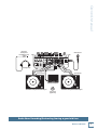
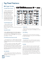
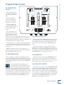
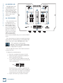
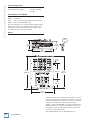
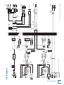
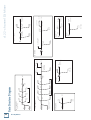
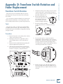
1
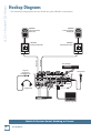
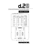
2-Channel DJ Mixer with FireWire Option
OWNER’S MANUAL
MIC
PGM
OL
SIG
+3
48V
PGM
OO
2
CONTROL
SOURCE
LINE/
PHONO
OFF
ON
+50
LEVEL
1
SOURCE
U
U
LINE/
PHONO
MAX
OO
CD
LEVEL
EQ
MAIN
CD
EQ
MAX
OO
EQ
MAX
LEVEL
LEVEL
BOOTH
U
U
HIGH
-15
HIGH
+15
HIGH
KILL
+10
KILL
STEREO
MONO
OO
MAX
LEVEL
+10
FX
U
MID
MID
MID
OO
-15
+15
KILL
+10
KILL
+10
KILL
+10
KILL
+10
+15
SEND
U
LOW
LOW
LOW
OO
+15
RETURN
-15
+15
PHONES
U
PGM
MAIN
ON
FX
FX
OO
MAX
LEVEL
PGM SOURCE
BAL
PAN
L
BAL
L R
R
PGM
1
L R
1
2
PGM
TRANSFORM
TRANSFORM
MAIN
L
R
OL
OL
OL
10
10
10
7
7
7
4
4
4
2
2
2
0
0
0
2
2
2
4
4
4
7
7
7
10
10
10
20
20
20
30
30
30
REVERSE
infinium
contact-free
cross-fader
REVERSE
A
REVERSE
B
2
d.2 2-channel DJ Mixer
Important Safety Instructions
13. Unplug this apparatus during lightning storms or when unused for long
periods of time.
1. Read these instructions.
2. Keep these instructions.
14. Refer all servicing to qualified service personnel. Servicing is required
when the apparatus has been damaged in any way, such as powersupply cord or plug is damaged, liquid has been spilled or objects have
fallen into the apparatus, the apparatus has been exposed to rain or
moisture, does not operate normally, or has been dropped.
3. Heed all warnings.
4. Follow all instructions.
5. Do not use this apparatus near water.
6. Clean only with dry cloth.
7. Do not block any ventilation openings. Install in accordance with the
manufacturer’s instructions.
8. Do not install near any heat sources such as radiators, heat registers,
stoves, or other apparatus (including amplifiers) that produce heat.
9. Do not defeat the safety purpose of the polarized or grounding-type
plug. A polarized plug has two blades with one wider than the other.
A grounding-type plug has two blades and a third grounding prong.
The wide blade or the third prong are provided for your safety. If the
provided plug does not fit into your outlet, consult an electrician for
replacement of the obsolete outlet.
10. Protect the power cord from being walked on or pinched particularly at
plugs, convenience receptacles, and the point where they exit from the
apparatus.
11. Only use attachments/accessories specified by the manufacturer.
12. Use only with a cart, stand, tripod, bracket, or table specified by the
manufacturer, or sold with the apparatus. When a cart is used, use
caution when moving the cart/apparatus combination to avoid injury
from tip-over.
PORTABLE CART WARNING
Carts and stands - The
Component should be used
only with a cart or stand
that is recommended by
the manufacturer.
A Component and cart
combination should be
moved with care. Quick
stops, excessive force, and
uneven surfaces may cause
the Component and cart
combination to overturn.
CAUTION
AVIS
RISK OF ELECTRIC SHOCK
DO NOT OPEN
RISQUE DE CHOC ELECTRIQUE
NE PAS OUVRIR
CAUTION: TO REDUCE THE RISK OF ELECTRIC SHOCK
DO NOT REMOVE COVER (OR BACK)
NO USER-SERVICEABLE PARTS INSIDE
REFER SERVICING TO QUALIFIED PERSONNEL
ATTENTION: POUR EVITER LES RISQUES DE CHOC
ELECTRIQUE, NE PAS ENLEVER LE COUVERCLE. AUCUN
ENTRETIEN DE PIECES INTERIEURES PAR L'USAGER. CONFIER
L'ENTRETIEN AU PERSONNEL QUALIFIE.
AVIS: POUR EVITER LES RISQUES D'INCENDIE OU
D'ELECTROCUTION, N'EXPOSEZ PAS CET ARTICLE
A LA PLUIE OU A L'HUMIDITE
The lightning flash with arrowhead symbol within an equilateral
triangle is intended to alert the user to the presence of uninsulated
"dangerous voltage" within the product's enclosure, that may be
of sufficient magnitude to constitute a risk of electric shock to persons.
Le symbole éclair avec point de flèche à l'intérieur d'un triangle
équilatéral est utilisé pour alerter l'utilisateur de la présence à
l'intérieur du coffret de "voltage dangereux" non isolé d'ampleur
suffisante pour constituer un risque d'éléctrocution.
The exclamation point within an equilateral triangle is intended to
alert the user of the presence of important operating and maintenance
(servicing) instructions in the literature accompanying the appliance.
Le point d'exclamation à l'intérieur d'un triangle équilatéral est
employé pour alerter les utilisateurs de la présence d'instructions
importantes pour le fonctionnement et l'entretien (service) dans le
livret d'instruction accompagnant l'appareil.
2
d.2 DJ Mixer
15. This apparatus shall not be exposed to dripping or splashing, and no
object filled with liquids, such as vases or beer glasses, shall be placed
on the apparatus.
16. This apparatus has been designed with Class-I construction and must
be connected to a mains socket outlet with a protective earthing connection (the third grounding prong).
17. This apparatus has been equipped with an all-pole, rocker-style AC
mains power switch. This switch is located on the rear panel and
should remain readily accessible to the user.
18. This apparatus does not exceed the Class A/Class B (whichever is
applicable) limits for radio noise emissions from digital apparatus as
set out in the radio interference regulations of the Canadian Department
of Communications.
ATTENTION — Le présent appareil numérique n’émet pas de bruits
radioélectriques dépassant las limites applicables aux appareils numériques de
class A/de class B (selon le cas) prescrites dans le réglement sur le brouillage
radioélectrique édicté par les ministere des communications du Canada.
19. Exposure to extremely high noise levels may cause permanent hearing
loss. Individuals vary considerably in susceptibility to noise-induced
hearing loss, but nearly everyone will lose some hearing if exposed to
sufficiently intense noise for a period of time. The U.S. Government’s
Occupational Safety and Health Administration (OSHA) has specified
the permissible noise level exposures shown in the following chart.
According to OSHA, any exposure in excess of these permissible limits
could result in some hearing loss. To ensure against potentially dangerous exposure to high sound pressure levels, it is recommended that all
persons exposed to equipment capable of producing high sound pressure levels use hearing protectors while the equipment is in operation.
Ear plugs or protectors in the ear canals or over the ears must be worn
when operating the equipment in order to prevent permanent hearing
loss if exposure is in excess of the limits set forth here.
Duration Per Day
In Hours
Sound Level dBA,
Slow Response
8
90
6
92
4
95
3
97
2
100
1.5
102
1
105
0.5
110
0.25 or less
115
Typical
Example
Duo in small club
Subway Train
Very loud classical music
Dave screaming at Steve about deadlines
Loudest parts at a rock concert
WARNING — To reduce the risk of fire or
electric shock, do not expose this apparatus
to rain or moisture.
Owner’s Manual
Table of Contents
Safety Instructions................................... 2
Introduction...............................................4
Getting Started......................................... 5
READ THIS PAGE!!....................................................5
Hookup Diagrams.....................................6
Rear Panel Features................................ 10
Top Panel Features...................................12
Microphone Input Section .................................12
Program Input Section......................................... 13
Control Section......................................................14
Program Output Section..................................... 15
Front Panel Features ...............................17
Appendix A: Service Information....... 18
Warranty Service...................................................18
Troubleshooting....................................................18
Repair .......................................................................19
Appendix B: Connections .....................20
Appendix C: Technical Info ...................21
Specifications.........................................................21
Block Diagram........................................................23
Gain Structure Diagram...................................... 24
Appendix D: Transform Switch
Rotation and Fader Replacement......25
Limited Warranty...................................27
Don’t forget to visit our website at www.mackie.com for more
information about this and other Mackie products.
Part No. 0014096 Rev. A 7/05
©2005 LOUD Technologies Inc. All Rights Reserved. Printed in China.
Owner’s Manual
3
d.2 2-channel DJ Mixer
Introduction
Thank you for choosing a Mackie d.2 Premium VCA
Mixer for scratch and club DJs. It contains all your favorite features in a scratch mixer, along with significant
extras that you will come to appreciate.
The d.2 is the first DJ mixer made by Mackie. We were
able to apply our extensive knowledge of mixer design
to the d.2, making it a truly professional product with
the high-end performance you’ve come to expect from
Mackie. Features like our “built like a tank” construction, premium analog circuitry, infinium™ contact-free
crossfader, optional FireWire™ connectivity, and “Planet
Earth” power supply add value to the d.2 not found in
any other scratch mixer in its class.
FEATURES
•
Mighty strong construction to withstand the
rigors of DJ work.
•
Integrated rack ears (Odyssey Battle Bridge™
compatible).
•
Removable top panel provides access to the
rotatable transform switches and to the
user-replaceable faders.
•
Premium VCA-based design offers extremely
smooth fades and cross fades with very low
distortion characteristics for warm, hearty
sounding mixes.
•
Mackie mic preamp with 3-band EQ for proquality vocals through the d.2.
•
XLR main outputs with Mic/Line switch (mic
position allows stage connections with no D.I.
boxes required).
•
RCA main outs with Live/Record switch
(Record position delivers a pre-main out).
•
Endless-life optical crossfader from the UKbased Infinium, with adjustable mechanical
tension accessible from the top panel.
Please write your serial number here for future
reference (i.e., insurance claims, tech support,
return authorization, etc.)
Purchased at:
•
Optional user-installable FireWire card receives
four program channels from PC/Mac and sends
a stereo L-R recording stream to PC/Mac.
•
Program faders and Crossfader have variable
contour curves and reverse switches.
•
Ultra bright blue/white main meters plus
individual program meters for cueing and beat
matching.
•
Separate mono/stereo switchable booth output
on balanced TRS connectors.
•
Stereo FX loop for outboard effects.
•
“Planet Earth” power-supply operates on voltages between 100 and 240 VAC.
•
Standard IEC power receptacle and power cord.
HOW TO USE THIS MANUAL
We know that many of you can’t wait to get your new
mixer hooked up, and you’re probably not going to read
the manual first (sigh!). So the first section after this
Introduction is a Getting Started guide to help you get
the mixer set up fast so you can start using it right away.
Right after that are the ever popular hook-up diagrams
that show you some typical setups.
Then, when you have time, read the Features Description section. This describes every knob, button, and
connection point on the d.2, roughly following the signal
flow through the mixer from top to bottom.
Throughout this section you’ll find illustrations with
each feature numbered. If you want to know more about
a feature, simply locate it on the appropriate illustration, notice the number attached to it, and find that
number in the nearby paragraphs.
This icon marks information that is critically
important or unique to the d.2. For your own
good, read them and remember them. They
will be on the final test.
This icon leads you to in-depth explanations
of features and practical tips. While not
mandatory, they usually have some valuable
nuggets of information.
Appendix B is a section on connectors: XLR connectors, TRS balanced connectors, TS unbalanced connectors, and RCA unbalanced connectors.
Appendix C shows the d.2 specifications, a block diagram, and a gain structure diagram.
Date of purchase:
4
d.2 DJ Mixer
Appendix D shows how to adjust the position of the
transform switches, and how to replace the faders if you
ever have to.
READ THIS PAGE!!
Even if you never reads manuals, please
read and digest the safety instructions
on page 2, and this page before you
begin using the d.2 mixer.
Set the Levels
To set the LEVEL controls, it’s not even necessary
to hear what you’re doing at the outputs of the mixer.
If you want to listen while you work, plug headphones
into the PHONES jack on the front panel, then set the
PHONES knob up a little.
1.
Select the input using the SOURCE switch.
2.
Play something into the selected input. Be sure
that the volume of the input source is the same as
it would be during normal use. If it isn’t, you might
have to readjust these levels during the middle of a
set.
Zero the Controls
1.
Turn the rear panel POWER switch off.
2.
Turn down the LEVEL controls for MIC, PGM 1 and
PGM 2, and center all EQ, PAN, and BAL controls.
3.
Center the TRANSFORM switch. There will be no
output, but the PROGRAM METER will still work.
3.
Set all push button switches to their “out” positions.
4.
4.
In the CONTROL section (right hand side), turn all
the rotary knobs down, and the switches out.
Adjust the channel’s rotary LEVEL control so that
the LEDs on the PROGRAM meter stay around “0”
and +4, and never go higher than “+7.”
5.
Set the PROGRAM Faders fully down.
5.
Apply some EQ if needed, (return to step 4 if you
do, just to check the levels are still OK).
6.
On the front panel, set the REVERSE switches out.
6.
Repeat for the other channel (if you want to).
7.
Center the CROSSFADER.
Connections
If you already know how you want to connect the d.2,
go ahead and connect the inputs and outputs the way
you want them. If you just want to get sound through
the d.2 mixer, follow these steps:
1.
Plug a signal source to the d.2. This could be a:
• Microphone into the MIC input
•
Turntable into a PHONO input (push in the
rear panel LINE/PHONO switch)
•
Line-level source such as a CD player into the
PHONO input (push out the LINE/PHONO
switch)
•
Set the MIC Levels
1.
To level the microphone input, keep the ON button
off, and talk or sing at your highest expected level.
2.
Adjust the MIC LEVEL until the OL LED next to it
only comes on occasionally.
Instant Mixing
1.
To get sound out of the speakers, press the TRANSFORM switch up (the latched position), turn up the
PROGRAM fader, and slowly rotate the MAIN control
to a comfortable listening level.
2.
Sing and play. You’re a star! Bring in the other
channel, play with the CROSSFADER, and generally
have fun.
Line-level source such as a CD player into a CD
input.
2.
If you are using the PHONO input, make sure you
set the LINE/PHONO switch correctly.
3.
Connect cords from the d.2’s MAIN OUTs (XLR or
RCA connectors on the rear panel) to your powered
speakers or amplifier.
4.
Plug in the detachable linecord, connect it to a live
AC outlet, and turn on the d.2’s POWER switch.
5.
If you have powered speakers, turn them on. Otherwise, hook up your speakers to the amp and turn it
on. Adjust your powered speaker or amplifier level
controls to however the manufacturer recommends.
(This is usually all the way up.)
Owner’s Manual
Getting Started
Other Nuggets of Wisdom
•
Always turn down the MAIN, BOOTH, and PHONE
knobs before making any connections.
•
When you shut down your equipment, turn off the
amplifiers first. When powering up, turn on the
amplifiers last.
•
Never listen to loud music for prolonged periods.
Please see the Safety Instructions on page 2 for
information on hearing protection.
Owner’s Manual
5
d.2 2-channel DJ Mixer
Hookup Diagrams
(The following hookup diagrams show the d.2 with the optional FireWire card installed.)
SRM450
Powered Speaker
Main Right
SRM450
Powered Speaker
Main Left
SWA1501
Powered Subwoofer
Main Left
Main Right
SWA1501
Powered Subwoofer
Pro CD Player
Plug into
front panel
headphone jack
Microphone
DESIGNED BY MACKOIDS IN WOODINVILLE, WA, USA • MANUFACTURED IN CHINA
FABRIQUE EN CHINE • COPYRIGHT ©2005 • "MACKIE", AND THE RUNNING MAN
FIGURE ARE TRADEMARKS OF LOUD TECHNOLOGIES, INC. • PATENT PENDING.
BOOTH
MAIN OUT
L
R
LINE
MIC
FX
L
SEND
R
R
L
RETURN
R
~100-240 VAC 50-60Hz 20W
ON
PHONO
L
CD
R
LIVE
RECORD
LINE
PHONO
L
PGM 1
PGM 2
L
PHONO
L
L
R
R
GND
CD
MIC
L
R
LINE
PHONO
GND
SERIAL / DATE CODE
R
FIREWIRE
Headphones
Effects Processor
Laptop Computer
Mobile DJ System: Rental, Wedding, or Funeral
6
d.2 DJ Mixer
Owner’s Manual
Plug into
front panel
headphone jack
Microphone
DESIGNED BY MACKOIDS IN WOODINVILLE, WA, USA • MANUFACTURED IN CHINA
FABRIQUE EN CHINE • COPYRIGHT ©2005 • "MACKIE", AND THE RUNNING MAN
FIGURE ARE TRADEMARKS OF LOUD TECHNOLOGIES, INC. • PATENT PENDING.
BOOTH
MAIN OUT
L
R
LINE
MIC
FX
L
SEND
R
R
L
RETURN
R
ON
PHONO
L
CD
R
LIVE
RECORD
~100-240 VAC 50-60Hz 20W
LINE
PHONO
L
PGM 1
PGM 2
L
PHONO
L
L
R
R
GND
CD
MIC
L
R
LINE
PHONO
GND
SERIAL / DATE CODE
R
FIREWIRE
Headphones
ground wire
ground wire
Laptop Computer
Turntable with phono-level output
cup of tea
(optional)
Turntable with phono-level output
Radio Show Recording/Podcasting/having a good old time
Owner’s Manual
7
d.2 2-channel DJ Mixer
SRM450
Powered Speaker
Main Right
SRM450
Powered Speaker
Main Left
SWA1501
Powered Subwoofer
Main Left
Main Right
SWA1501
Powered Subwoofer
Plug into
front panel
headphone jack
Microphone
DESIGNED BY MACKOIDS IN WOODINVILLE, WA, USA • MANUFACTURED IN CHINA
FABRIQUE EN CHINE • COPYRIGHT ©2005 • "MACKIE", AND THE RUNNING MAN
FIGURE ARE TRADEMARKS OF LOUD TECHNOLOGIES, INC. • PATENT PENDING.
BOOTH
MAIN OUT
L
R
LINE
MIC
FX
L
SEND
R
R
L
RETURN
R
ON
PHONO
L
CD
R
LIVE
RECORD
~100-240 VAC 50-60Hz 20W
LINE
PHONO
L
PGM 1
PGM 2
L
PHONO
L
L
R
R
GND
CD
MIC
L
R
LINE
PHONO
GND
SERIAL / DATE CODE
R
FIREWIRE
Headphones
ground wire
Turntable with phono-level output
ground wire
Turntable with phono-level output
Two-Turntable Portable System
8
d.2 DJ Mixer
Owner’s Manual
SA1532z
Powered Speaker
Main Left
SA1532z
Powered Speaker
Main Right
SWA1801
Powered
Subwoofers
SWA1801
Powered
Subwoofers
CD Turntable (PGM 1)
Main Left
Main Right
CD Turntable (PGM 2)
Plug into
front panel
headphone jack
Microphone
DESIGNED BY MACKOIDS IN WOODINVILLE, WA, USA • MANUFACTURED IN CHINA
FABRIQUE EN CHINE • COPYRIGHT ©2005 • "MACKIE", AND THE RUNNING MAN
FIGURE ARE TRADEMARKS OF LOUD TECHNOLOGIES, INC. • PATENT PENDING.
BOOTH
MAIN OUT
L
R
LINE
MIC
FX
L
SEND
R
R
L
RETURN
R
ON
PHONO
CD
L
R
LIVE
RECORD
~100-240 VAC 50-60Hz 20W
LINE
PHONO
L
PGM 1
PGM 2
L
PHONO
L
L
R
R
GND
MIC
CD
L
R
LINE
PHONO
GND
SERIAL / DATE CODE
R
Headphones
FIREWIRE
Booth Right
Booth Left
ground wire
ground wire
Laptop Computer
Turntable (PGM 2)
with phono-level output
SRM450 Powered Speaker
Booth Left
Turntable (PGM 1)
with phono-level output
SRM450 Powered Speaker
Booth Right
Club System
Owner’s Manual
9
d.2 2-channel DJ Mixer
Rear Panel Features
DESIGNED BY MACKOIDS IN WOODINVILLE, WA, USA • MANUFACTURED IN CHINA
FABRIQUE EN CHINE • COPYRIGHT ©2005 • "MACKIE", AND THE RUNNING MAN
FIGURE ARE TRADEMARKS OF LOUD TECHNOLOGIES, INC. • PATENT PENDING.
BOOTH
MAIN OUT
L
R
LINE
MIC
FX
L
SEND
R
R
L
RETURN
R
~100-240 VAC 50-60Hz 20W
ON
LINE
PHONO
L
CD
PHONO
L
L
R
R
GND
CD
MIC
L
R
LINE
PHONO
GND
SERIAL / DATE CODE
R
FIREWIRE
(ACCESSORY CARD REQUIRED)
1. MIC Input
5. GND Terminal
This is a Neutrik “combo” input connector that accepts either a balanced male XLR connector or a 1/4"
balanced or unbalanced connector. Use an XLR connector for low-impedance microphones and a 1/4" connector for high-impedance microphones.
These terminals are provided to connect a ground
wire from your turntable(s) to the d.2. Most turntables
provide a ground wire to connect to the preamp for the
purpose of eliminating “hum” in the audio signal. Simply
turn the ground terminal on the d.2 counter-clockwise
to loosen it, wrap the end of the ground wire clockwise
around the terminal, and hand-tighten the ground terminal for a secure ground connection.
The MIC Input signal is routed through the MIC Input
Section, MIC EQ, and then to the Main Mix bus.
2. CD Inputs
These RCA jacks accept a stereo line-level signal from
a CD player or other line-level playback device (such as
an MP3 player or DVD audio).
3. LINE/PHONO Inputs
These RCA jacks accept a stereo phono-level signal
from a turntable (when the LINE/PHONO [4] switch
is pushed in), or from a line-level playback device such
as a CD player or MP3 player (when the LINE/PHONO
switch is out). Check that your turntable has a phonolevel output and a Moving Magnet cartridge.
4. LINE/PHONO Switch
If you connect a turntable with phono-level outputs
to the LINE/PHONO inputs [3], push this switch in to
select the phono-level input stage, which includes an
RIAA preamp for proper re-equalization of the incoming
phono signal.
If you are connecting a line-level playback device like
a CD or MP3 player, leave this switch out to select the
line-level preamp.
Do not press it in if you have a line-level
signal connected.
10
PHONO
L
R
LIVE
RECORD
PGM 1
PGM 2
L
d.2 DJ Mixer
6. Stereo FX SEND
These 1/4" TRS jacks provide a balanced line-level
output signal from the stereo FX Send bus. Use these to
connect to the inputs of an external effects processor.
You can also use an unbalanced 1/4" TS cable to make
this connection.
7. Stereo FX RETURN
These 1/4" TRS jacks accept a balanced line-level
signal from an external effects processor. They will also
accept an unbalanced 1/4" TS connector.
If you are using a stereo effects processor, connect its
left and right outputs to the corresponding left and right
FX RETURN jacks. If it is a mono effects processor, connect its output signal to the left FX RETURN jack, and it
will appear on both the left and right Main Mix bus.
8. BOOTH Outputs
These 1/4" TRS jacks provide a balanced line-level
signal from the Main Mix bus, prior to the rotary MAIN
LEVEL control [32]. Use these to connect to a pair
of powered monitor speakers (or to the inputs of an
amplifier powering the monitor speakers in the booth).
9. XLR MAIN OUTs
These male XLR connectors provide a balanced micor line-level signal from the MAIN LEVEL control [32].
The LINE/MIC Switch [10] determines if it is a miclevel or line-level output. Connect these to the balanced
inputs of the active speakers, or power amplifier(s)
powering your main speakers.
If you are connecting the MAIN OUT of the d.2 to an
unbalanced input, use the RCA Main Outs [11] instead.
MAIN LEVEL control. This allows you to make a stereo
recording that is not affected by Main Out level changes
during a performance.
13. POWER Switch
When the POWER switch is turned ON, power is supplied to the d.2 and the cool blue EQ knobs light up.
14. Power Receptacle
This is a standard 3-prong IEC power connector. Connect the detachable linecord (included in the box with
your d.2) to the power receptacle, and plug the other
end of the linecord into an AC outlet.
Note: Balanced connections offer better immunity to
external noise (specifically, hum and buzz) than unbalanced connections. Because of this, it is the preferred
interconnect method, especially in cases where very
long lengths of cable are being used. A long unbalanced
cable carries with it more opportunity for noise to get
into the system — having balanced cables means very
little noise will enter the system. If you must use an
unbalanced connection, keep the cable length to 10 feet
or less (3 meters).
The d.2 has a universal power supply that can accept
any AC voltage from 100 VAC to 240 VAC. No need for
voltage select switches. It will work virtually anywhere
in the world. That’s why we call it a “Planet-Earth”
power supply! This also means that it is less susceptible
to voltage sags or spikes, providing greater electromagnetic isolation and better protection against AC line
noise.
10. LINE/MIC Switch
FireWire (a.k.a. IEEE 1394) is a high-speed serial I/O
interface for connecting digital devices, with more than
30 times the bandwidth of USB 1.1. You can install the
optional FireWire card here, to provide two FireWire
connectors for transferring digital audio to and from
your laptop computer or digital audio workstation
(DAW) with absolute zero latency.
If you are connecting the XLR MAIN OUTs [9] to linelevel inputs like a power amplifier’s inputs, leave this
switch out, in the LINE position.
If you are using the d.2 as a submixer and connecting
the XLR MAIN OUTS to the mic inputs of another mixer,
push this switch in to the MIC position. This inserts a
30 dB pad to reduce the output signal to a mic level.
This great feature allows you to connect the d.2 output
directly to a snake without using direct boxes.
11. RCA Main Outs
These RCA connectors provide an unbalanced linelevel signal from the MAIN OUT, either pre- or postMAIN LEVEL control [32], depending on the setting of
the LIVE/RECORD switch [12].
12. LIVE/RECORD Switch
When this switch is out (LIVE position), the RCA
Main Outs provide the signal just after the MAIN LEVEL
control [32], so it essentially provides the same signal
as the XLR MAIN OUTs [9], except it is an unbalanced
signal rather than a balanced one.
When this switch is pushed in (RECORD position),
the RCA Main Outs provide the signal just prior to the
Owner’s Manual
If you only have one monitor speaker, just use one of
the BOOTH Outputs and push in the BOOTH STEREO/
MONO switch [34] in the CONTROL section on the top
panel.
15. FIREWIRE I/O Option
FIREWIRE
The FireWire interface provides a stereo main output
to your computer. The signals are pre-MAIN LEVEL control [32], so they are independent of any adjustments
made to the MAIN LEVEL control. This allows you to
record your live performance directly to your laptop.
The FireWire interface also lets you use your computer to playback music for mixing on the d.2. It provides
a return for four signals, which can be selected as the
program source for PGM 1 and PGM 2. Assign two channels (or a stereo pair) to ASIO or CoreAudio outputs 1
and 2 for PGM 1, and two channels (or a stereo pair) to
outputs 3 and 4 for PGM 2.
The FireWire card can easily be installed with the
help of a small screwdriver. Ask your Mackie dealer
about it. (The FireWire card, not the screwdriver.) Each
card comes with installation instructions that I have
to write before the boss gets back from his vacation in
Gary, Indiana.
Owner’s Manual
11
d.2 2-channel DJ Mixer
Top Panel Features
MIC Input Section
16. MIC LEVEL Control
This knob adjusts the gain
of the mic preamp for any
microphone plugged into the
MIC input jack [1]. It ranges
from +13 dB to +63 dB of
gain. Adjust this knob so
that the loudest speaking or
shouting that you do into the
microphone just barely lights
the OL LED [18]. This gives
you the best signal-to-noise
ratio for the mic preamp.
MIC
PGM
OL
SIG
+3
48V
OFF
ON
+50
LEVEL
2
CONTROL
U
LINE/
PHONO
MAX
OO
CD
LEVEL
MAIN
CD
EQ
MAX
OO
MAX
LEVEL
LEVEL
EQ
BOOTH
U
U
HIGH
-15
HIGH
+15
HIGH
KILL
+10
KILL
STEREO
MONO
OO
MAX
LEVEL
+10
FX
U
MID
MID
MID
OO
-15
+15
KILL
+10
KILL
+10
KILL
+10
KILL
+10
+15
SEND
U
LOW
LOW
LOW
OO
+15
RETURN
-15
+15
PHONES
U
PGM
MAIN
FX
FX
OO
MAX
LEVEL
PGM SOURCE
17. MIC SIGNAL LED
BAL
PAN
L
R
This green LED is a signal
present indicator. It lights
when the microphone signal
reaches –20 dBu, to give you a clue that the microphone
is working.
18. MIC OL LED
This red LED lights when the microphone signal
reaches 6 dB below clipping. It’s okay if this LED blinks
occasionally, but if it is blinking frequently or lit continuously, turn down the MIC LEVEL control [16] until
it just blinks occasionally.
19. 48V Phantom Power Switch
If your microphone is a condenser design, it probably
requires phantom power to operate. Push in this switch
to supply 48 VDC to pins 2 and 3 of the XLR microphone
connector.
Dynamic microphones, like Shure’s SM57 and SM58,
do not require phantom power. However, phantom
power will not harm most dynamic microphones should
you accidentally plug one in while the phantom power
is turned on. Check your microphone’s user’s manual if
you are not sure whether your microphone needs phantom power or not.
20. HIGH EQ
This knob gives your mic signal up to 15 dB of boost
and cut at 12 kHz and above. At the center position the
HIGH EQ has no effect on the signal.
d.2 DJ Mixer
PGM
SOURCE
LINE/
PHONO
OO
EQ
ON
12
1
SOURCE
U
BAL
L R
1
2
L R
21. MID EQ
This knob gives you up to 15 dB of boost and cut at
2.5 kHz. At the center position the MID EQ has no effect
on the signal.
22. LOW EQ
This knob gives you up to 15 dB of boost and cut at
80 Hz and below. At the center position the LOW EQ has
no effect on the signal.
23. ON Switch
Press this switch in to send the microphone signal to
the MAIN outputs, otherwise, your dulcet tones will not
be heard, and people will say “huh?”
24. PAN
This knob adjusts the amount of microphone signal
that is sent to the left versus the right main outputs.
When the knob is turned hard left, the signal feeds only
the left main out, and when the knob is turned hard
right, it only feeds the right main out. When the knob is
in the center, the microphone signal is sent equally to
the left and right main mix. The fiendish design of the
pan circuit allows “constant pan power,” where the average audio output level remains constant for all positions
of the PAN control.
25. LEVEL Control
This knob adjusts the gain of the PGM input signals
selected by the position of the SOURCE Select switch
[26]. This knob ranges from off to +13 dB of gain at
maximum. Adjust this with your good eye on the PROGRAM METERS [42], so the level is typically bouncing
between the 0 and +4 LEDs.
26. SOURCE Select Switch
This switch selects one of three possible input sources
for the PGM channel:
FireWire: The signal coming in from the optional
FireWire interface is selected as the source.
30. FX Switch
Press this switch in to tap the PGM signal to the FX
SEND outputs. This allows you to send the signal to an
external effects processor, or even provide a direct feed
for the PGM signal to another mixer. This switch will
route the PGM signal to the FX send output connectors,
interrupting the signal to the Main Outputs. If there
is no effects processor connected to the FX send and
returns, then the PGM signal is muted.
31. BAL
Owner’s Manual
Program Input Section
This knob works like the balance control on a home
stereo. Turning the knob to the left turns down the right
side, and turning the knob to the right turns down the
left side. When the BAL control is in the center, the left
and right sides are equally as loud (assuming the left
and right inputs are equal loudness).
LINE/PHONO: The signal connected to the PHONO
connectors on the rear panel is selected. This
could be from a turntable or from a line-level
playback device, depending on the setting of
the LINE/PHONO switch [4].
CD: The signal connected to the CD connectors on
the rear panel is selected.
You could have a signal coming in on all three inputs,
and quickly change from one input source to another
using this heavy duty switch.
27. HIGH EQ
This knob gives you up to 10 dB of boost at 4 kHz and
above, and turns off the signal at 4 kHz and above when
the knob is turned to the KILL position. At the center
position, the HIGH EQ has no effect on the signal.
28. MID EQ
This knob gives you up to 10 dB of boost at 1 kHz, and
turns off the signal at 1 kHz when the knob is turned to
the KILL position. At the center position, the MID EQ
has no effect on the signal.
29. LOW EQ
This knob gives you up to 10 dB of boost at 300 Hz
and below, and turns off the signal at 300 Hz and below
when the knob is turned to the KILL position. At the
center position, the LOW EQ has no effect on the signal.
Note: When all three EQ knobs are turned to the KILL
position, the signal is effectively muted and no signal
passes through to the output.
Owner’s Manual
13
d.2 2-channel DJ Mixer
Control Section
32. MAIN LEVEL
Control
MIC
This knob adjusts the
main output level at the
MAIN OUT XLRs [9]
(and to the RCA Main
Outs [11] when the
LIVE/RECORD switch
[12] is out). (Remember, when the LIVE RECORD switch is pushed
in, the RCA Main Outs
are not affected by the
MAIN LEVEL control.)
PGM
OL
SIG
+3
48V
LEVEL
PGM
OO
2
CONTROL
SOURCE
LINE/
PHONO
OFF
ON
+50
1
SOURCE
U
U
LINE/
PHONO
MAX
OO
CD
LEVEL
EQ
MAIN
CD
EQ
MAX
OO
MAX
LEVEL
LEVEL
EQ
BOOTH
U
U
HIGH
-15
HIGH
+15
HIGH
KILL
+10
KILL
STEREO
MONO
OO
MAX
LEVEL
+10
FX
U
MID
MID
MID
OO
-15
+15
KILL
+10
KILL
+10
KILL
+10
KILL
+10
+15
SEND
U
LOW
LOW
LOW
OO
+15
RETURN
-15
+15
PHONES
U
PGM
MAIN
ON
FX
FX
OO
MAX
LEVEL
PGM SOURCE
33. BOOTH LEVEL
Control
BAL
PAN
L
R
This knob adjusts
the output level at the
BOOTH outputs [8].
34. STEREO/MONO Switch
With this switch up, the BOOTH outputs [8] provide
a stereo left and right output of the main mix. Push the
switch in to combine the left and right signals to mono if
you only have one booth monitor speaker.
35. FX SEND LEVEL Control
This knob controls the amount of signal being sent to
FX SEND outputs [6]. Adjust this knob to provide an
appropriate input signal level to your external effects
processor (or whatever you have connected to the FX
SENDs). It ranges from off to +13 dB at maximum.
Note: The FX SENDs are affected by the TRANSFORM
switches [40], so if you mute a PGM channel with the
TRANSFORM switch, the FX SEND for that PGM channel is muted as well.
36. FX RETURN LEVEL Control
This adjusts the signal level coming from your external effects processor via the FX RETURN jacks [7]. Use
it to adjust the processed signal going to the main mix
bus. It ranges from off to +13 dB at maximum.
L R
BAL
1
2
L R
37. PHONES LEVEL Control
This controls the volume of the PHONES output from
off to maximum gain.
Turn it to minimum before connecting and
putting on headphones. Increase it slowly to
a safe listening level. See page 17.
38. PGM/MAIN Switch
Use this switch to select the source for the headphones signal. When the switch is up (PGM position),
the signal is tapped just after the BAL control [30] on
the PGM channels. You can use the PGM SOURCE crossfader [39] to fade between PGM 1 and PGM 2.
When the switch is down (MAIN position), the signal
is tapped from the Main Mix bus, just before the MAIN
LEVEL control [32].
39. PGM SOURCE Cue Crossfader
When the PGM/MAIN switch [38] is up (in the PGM
position), you can use this crossfader to listen to PGM
1 and PGM 2 in the headphones. When the crossfader
is all the way to the left, PGM 1 is heard in the headphones. When the crossfader is all the way to the right,
PGM 2 is heard in the headphones. When the knob is in
the center, the headphones get an even mix of PGM 1
and 2.
Note: When the PGM/MAIN switch is down (MAIN
position), this control has no effect on the PHONES
output.
14
d.2 DJ Mixer
40. TRANSFORM
Switch
The transform switch
has three positions: Latching, Center, and Momentary.
When the switch is
Latched, this program’s
signal is on, and passes
through to the outputs.
When the switch is in
the center position, this
program’s signal is muted
at the outputs and FX
Sends.
PGM
1
2
PGM
TRANSFORM
TRANSFORM
MAIN
L
R
OL
OL
OL
10
10
10
7
7
7
4
4
4
2
2
2
0
0
0
2
2
2
4
4
4
7
7
7
10
10
10
20
20
20
30
30
30
REVERSE
infinium
contact-free
cross-fader
The other position is a
momentary version of the
Latched position (in other
words, it won’t stay there
when you let go of it), and allows the signal to pass as
long as the switch is held down. Let go of the switch,
and the signal is muted again. This lets you quickly use
the transform switch for “stutter” effects.
If you prefer, you can rotate the Transform switch 45º
or 90º so the switch moves diagonally or horizontally instead of vertically. See Appendix D on page 25 for more
information.
REVERSE
A
Owner’s Manual
Program Output Section
REVERSE
B
42. PGM LEVEL METERS
These meters have 12 LEDs, ranging from –30 to +20
(OL). They indicate the summed-mono signal strength
of the PGM signals just before the BAL controls [31].
The meters are not affected by the PROGRAM faders
[41].
Note: If this switch is in the center position, the
program can still be heard and cued in the headphones
if the PGM/MAIN switch [38] is up.
Typically, you want to see these meters bouncing
between the “0” and the “+4” LEDs. It is okay if the OL
LED lights occasionally, but if it lights frequently or continuously, turn down the PGM LEVEL control [25] until
the OL LED blinks occasionally or not at all.
41. PROGRAM FADER
43. REVERSE LED
This controls the volume for the PGM signal being
sent to the Main Mix bus. The characteristics of how the
fader affects the audio signal are determined by the corresponding CONTOUR control [47] and the REVERSE
switch [48].
These light when the front-panel REVERSE switches
[48] have been activated for PGM 1 or PGM 2 faders.
They show that the fader direction-of-action is reversed.
(The meters are not reversed, just the faders.)
These faders have a very light touch
and are designed to last the lifetime of the
d.2. No audio passes through these faders.
Rather, they send a control voltage to a pair of VCAs
(Voltage-Controlled Amplifiers) that determine the gain
of the signal. This is a very good thing, by the way, as the
audio will not be affected by any scratchy electrical contacts, and the design allows for customizing the fader
action using the CONTOUR and REVERSE controls.
44. MAIN LEVEL METERS
These meters are similar to the PGM LEVEL METERS
[42], but indicate the signal strength of the Main outputs before the MAIN LEVEL control. As with the other
meters, you want to see the signals bouncing between
the “0” and the “+4” LEDs. It is okay if the OL LEDs light
occasionally, but if they light frequently or continuously,
turn down the PROGRAM FADERS [41] until the OL
LEDs blink occasionally, or not at all.
Owner’s Manual
15
d.2 2-channel DJ Mixer
45. REVERSE LED
PGM
This LED lights when
the REVERSE switch
[48] has been activated
for the Crossfader. For
more details, see the discussion of the REVERSE
switches [48] on the
next page.
1
TRANSFORM
TRANSFORM
MAIN
L
OL
OL
10
10
10
7
7
7
4
4
4
2
2
2
0
0
0
2
2
2
4
4
4
7
7
7
10
10
10
20
20
20
30
30
30
46. CROSSFADER
The crossfader is used
to fade between the
two PGM signals in the
MAIN outputs. When
the crossfader is all the
infinium
way to the left, PGM 1 is
heard in the MAIN outs.
When the crossfader is
all the way to the right,
PGM 2 is heard. When
the crossfader knob is
in the center, the MAIN outs get an even mix of PGM 1
and 2.
REVERSE
The characteristics of how the crossfader affects the
audio signal are determined by its corresponding CONTOUR control [47] and the REVERSE switch [48].
The crossfader is a high-quality
infinium™ contact-free optical digital fader,
designed to last the lifetime of the d.2 with
no degradation in quality.
You can adjust the tension of the fader movement to
your specific taste.
To adjust the crossfader tension:
1. Move the crossfader all the way to the left.
2. Remove the fader cap (knob) by grasping it
firmly and pulling straight up.
3. Use a small slot-head screwdriver to turn the
screw located through the hole on the left side
of the crossfader slot.
Rotate the screw clockwise to tighten the tension, and rotate the screw counter-clockwise to
loosen the tension. You might need a flashlight
to make sure you are lined up on the screw.
4. Replace the fader cap, and you’re all done.
d.2 DJ Mixer
R
OL
contact-free
cross-fader
16
2
PGM
REVERSE
A
REVERSE
B
PGM 1 FADER
CROSS FADER
PGM 2 FADER
REVERSE
REVERSE
REVERSE
SLOW
FAST
CONTOUR
SLOW
FAST
CONTOUR
SLOW
Owner’s Manual
Front Panel Features
FAST
CONTOUR
47. CONTOUR Controls
49. Headphones Jack
Use the CONTOUR controls to adjust how fast or
slow each fader responds to movement. In the SLOW
position, the faders respond in a linear fashion, increasing from minimum to maximum at the same rate. In
the FAST position, the faders respond logarithmically,
increasing from minimum to maximum very quickly, and
then changing very little for the remainder of the fader
travel. Adjust the CONTOUR controls between the two
extremes to get the fader response that works best for
your application.
This is where you plug in your stereo headphones. It is
a 1/4" TRS stereo jack.
The CONTOUR control for the crossfader works in
a similar fashion, crossfading linearly with the CONTOUR control in the SLOW position, and crossfading
very quickly with the CONTOUR control in the FAST
position. In fact, in the FAST position, the crossfading
occurs within the first 2 mm of fader travel. This is great
for “crabbing” techniques.
48. REVERSE Switches
Normally (with these switches out) when you move
the PGM 1 or PGM 2 faders up, the volume will increase.
When you move the crossfader left to right, PGM 1 will
fade into PGM 2.
These switches let you reverse the direction of the
action of the program faders and the crossfader:
With the PGM 1 or PGM 2 REVERSE switches on,
when you move the PGM 1 or PGM 2 faders up, the
volume will now decrease.
If you have the PGM/MAIN switch [38] up, you can
listen to the PGM 1 or PGM 2 signals, or a mix of both,
determined by setting the PGM SOURCE Slider [39].
The signals are taken just after the BAL controls [31],
but before the PROGRAM Faders [41].
If you have the PGM/MAIN switch [38] down, you can
listen to the MAIN MIX signals, taken just before the
MAIN LEVEL control [32].
The headphone volume is controlled by the PHONES
LEVEL control [37], and the position of the PGM
SOURCE Crossfader [39] if you are listening to PGM 1
or PGM 2.
WARNING: The headphone amp is designed to drive any standard headphones to
a very loud level. We’re not kidding! It can
cause permanent hearing damage. Even intermediate
levels may be painfully loud with some headphones. BE
CAREFUL!
Always start with the PHONES LEVEL
control [37] turned all the way down before
connecting headphones to the PHONES
jack, or making any connections. Keep it down until
you’ve put on the headphones. Set the PGM SOURCE
Slider [39] if you are listening to PGM 1 or PGM 2, then
turn up the PHONES LEVEL control [37] slowly. Why?
Always remember: “Engineers who fry their ears, find
themselves with short careers.”
With the Crossfader REVERSE switch on, when you
move the crossfader left to right, PGM 2 will fade into
PGM 1. (This is sometimes called a hamster switch.)
Note: These switches and the CONTOUR controls do
not affect the meters, just the faders.
Owner’s Manual
17
d.2 2-channel DJ Mixer
Appendix A: Service Information
Warranty Service
Details concerning Warranty Service are spelled out in
the Warranty section on page 27.
If you think your d.2 has a problem, please do everything
you can to confirm it before calling for service. Doing so
might save you from the deprivation of your mixer and
the associated suffering.
These may sound obvious to you, but here are some
things you can check. Read on:
Troubleshooting
•
If the FX button [30] is pressed on that channel,
make sure your effects processor is connected correctly and is working.
•
Try the same source signal in the other channel, set
up exactly like the suspect channel.
Bad Output
•
Is the associated level control (if any) turned up?
•
If it’s one of the MAIN OUTPUTS, try unplugging
the others. For example, if it’s the XLR LEFT MAIN
OUT, unplug the RCA LEFT OUT. If the problem
goes away, it’s not the mixer.
•
If a left output is presumed dead, switch the left
and right cords at the mixer end. If the problem
stays on the left side, it’s not the mixer.
No Power
•
Our favorite question: Is it plugged in?
•
Make sure the power cord is securely seated in the
IEC socket [14] and plugged all the way into the
AC outlet.
Bad Sound
•
Make sure the AC outlet is live (check with a tester
or lamp).
•
Make sure the rear panel POWER switch [13] is in
the ON position (up).
•
Are the EQ controls on the front panel illuminated?
If not, make sure the AC outlet is live.
•
Are all the lights out in your town? If so, contact
your local power company to get power restored.
•
If no LEDs are illuminated, and you are certain that
the AC outlet is live, it will be necessary to have
your d.2 serviced. There are no user serviceable parts
inside. Refer to “Repair” on the next page to find out
how to proceed.
•
Is the input connector plugged completely into the
jack?
•
Is it loud and distorted? Make sure the input
LEVEL control [25] is set correctly. Reduce the
signal level on the input source if possible.
•
If possible, listen to the signal with headphones
plugged into the input source device. If it sounds
bad there, it’s not the d.2 causing the problem.
•
If you are using a turntable with a phono-level output, and the sound is low and distorted, check that
the LINE/PHONO switch [4] is set to PHONO. Note
that the phono section requires your cartridge to be
a Moving Magnet type. It may be too low to amplify
the low levels of a Moving Coil type.
Noise/Hum
•
Turn down the FX RETURN knob [36]. If the noise
disappears, it’s coming from whatever is plugged
into the FX RETURNS [7].
•
Check that your turntable’s audio ground wire is
connected to the GND terminals [5].
•
Turn down each channel, one by one. If the noise
disappears, it’s coming from whatever is plugged
into that channel. Check your whatever.
•
Check the signal cables between the input sources
and the d.2. Disconnect them one by one. When the
noise goes away, you’ll know which input source is
causing the problem.
•
Sometimes it helps to plug all the audio equipment
into the same AC circuit so they share a common
ground.
Bad Channel
•
18
Check the TRANSFORM switch [40] is not in the
center position.
•
Is a fader or crossfader REVERSE LED [48] on?
•
Check the channel’s PROGRAM fader [41] is not
fully down.
•
Are that channel’s EQ controls all turned down?
•
Is the signal source turned up? Make sure the
signal level from the selected input source is high
enough to light up some of the PROGRAM METER
LEDs [42].
•
Is the correct input chosen with the SOURCE SELECT switch [26], and its PGM LEVEL [25] turned
up far enough?
d.2 DJ Mixer
Owner’s Manual
Repair
Service for Mackie products is available at a factoryauthorized service center. Service for Mackie products
living outside the United States can be obtained through
local dealers or distributors.
If your d.2 needs service, follow these instructions:
1.
Review the preceding troubleshooting suggestions.
Please.
2.
Call Tech Support at 1-800-898-3211, 7 am to 5 pm
PST, to explain the problem and request a Service
Request Number. Have your d.2’s serial number
ready. You must have an Service Request Number
before you can obtain warranty service.
3.
Keep this owner’s manual and the detachable linecord. We don’t need them to repair the mixer.
4.
Pack the mixer in its original package, including endcaps and box. This is VERY IMPORTANT.
Mackie is not responsible for any damage that
occurs due to non-factory packaging.
5.
Include a legible note stating your name, shipping
address (no P.O. boxes), daytime phone number,
Service Request Number, and a detailed description
of the problem, including how we can duplicate it.
6.
Write the Service Request Number in BIG PRINT on
top of the box. Units sent without the SR number will
be refused.
7.
Tech Support will tell you where to ship the d.2 for
repair. We suggest insurance for all forms of cartage.
8.
You will need to contact the authorized service center for their latest turn-around times. The d.2 must
be packaged in its original packing box, and must
have the Service Request Number on the box. Once
it’s repaired, the authorized service center will ship
it back by ground shipping, pre-paid (if it was a warranty repair).
Note: Under the terms of the warranty, you must ship
or drop-off the unit to an authorized service center.
The return ground shipment is covered for those
units deemed by us to be under warranty.
Note: You must have a sales receipt from
an authorized Mackie dealer for your
unit to be considered for warranty
repair.
Owner’s Manual
19
d.2 2-channel DJ Mixer
Appendix B: Connections
XLR Connectors
1/4" TS Phone Plugs and Jacks
The d.2 MIC combo input accepts 3-pin male XLR
connectors; the MAIN OUTs accept 3-pin female XLR
connectors. These are wired as follows, according to
standards specified by the AES (Audio Engineering
Society).
“TS” stands for Tip-Sleeve, the two connection points
available on a mono 1/4" phone jack or plug. They are
used for unbalanced signals.
SLEEVE
TIP
2
SHIELD
TIP
HOT
TIP
COLD
SHIELD
COLD 3
HOT
1
3
SLEEVE
1
3
1
1/4" TS Unbalanced Wiring:
Sleeve = Shield
Tip = Hot (+)
2
SHIELD
COLD
2
HOT
RCA Plugs and Jacks
XLR Balanced Wiring:
Pin 1 = Shield
Pin 2 = Hot (+)
Pin 3 = Cold (–)
1/4" TRS Phone Plugs and Jacks
“TRS” stands for Tip-Ring-Sleeve, the three connection
points available on a stereo 1/4" or balanced phone
jack or plug. TRS jacks and plugs are used for balanced
signals and stereo headphones:
Balanced Mono
RING SLEEVE
SLEEVE RING TIP
TIP
RING
TIP
SLEEVE
1/4" TRS Balanced Mono Wiring:
Sleeve = Shield
Tip = Hot (+)
Ring = Cold (–)
Stereo Headphones
RING SLEEVE
SLEEVE RING TIP
TIP
RING
TIP
SLEEVE
1/4" TRS Stereo Unbalanced Wiring:
Sleeve = Shield
Tip = Left
Ring = Right
20
SLEEVE
d.2 DJ Mixer
RCA-type plugs (also known as phono plugs) and jacks
are often used in home stereo and video equipment and
in many other applications. They are unbalanced and
electrically equivalent to a 1/4" TS phone plug.
SLEEVE
RCA Unbalanced Wiring:
Sleeve = Shield
Tip = Hot (+)
TIP SLEEVE
TIP
Specifications
Frequency Response :
Input Impedance:
Mic Input to any Output: (Trim at 0 dB):+0, –1 dB
20 Hz to 20 kHz
Mic Input:
2.4 kΩ balanced
CD/ Line Input:
20 kΩ balanced
Line/CD Input to any Output:
FX Return:
20 kΩ balanced
Phono Input:
47.5 kΩ shunted with 200 pF
Phono input to any Output:
±0.5 dB
20 Hz to 20 kHz
±1 dB of RIAA EQ curve
Maximum Output Levels:
Distortion (THD and IMD):
THD @ Main Output, 20 Hz to 20 kHz
Mic Input @ 30 dB Gain:
Less than 0.0075%
Line/CD Input @ 0 dB Gain:
Less than 0.0075%
Phono Input:
Less than 0.01%
XLR Main Output:
+22 dBu
RCA Main Output:
+22 dBu
Booth Output:
+22 dBu
FX Send:
+22 dBu
Phones:
15 volts rms into 8Ω (28 watts)
Owner’s Manual
Appendix C: Technical Info
THD @ Phones Output, 20 Hz to 20 kHz
Line Input @ 0 dB Gain:
Less than 0.03%
Main XLR/RCA Output:
SMPTE IMD @ +4 dBu Output:
Mic Input @ 30 dB Gain:
Line/CD Input @ 0 dB Gain:
Output Impedance:
Less than 0.008%
Booth Output:
150 Ω
Less than 0.008%
FX Send:
150 Ω
Phones:
25 Ω
Common Mode Rejection Ratio (CMRR):
Mic Input (Gain = maximum)
150 Ω
Greater than 60 dB
@ 1 kHz
Crosstalk:
Adjacent Inputs or Input to Main Output:
Less than –85 dB
@ 1 kHz
Equalization
Mic Channel
Low:
±15 dB @ 80 Hz
Mid:
±15 dB @ 2.5 kHz
High:
±15 dB @ 12 kHz
PGM Channel
Noise Characteristics:
Low:
+10/–inf dB @ 300 Hz
Equivalent Input Noise (E.I.N.) (20 Hz to 20 kHz):
Mid:
+10/–inf dB @ 1 kHz
Mic Input (150 Ω source impedance): Less than –123 dBu
High:
+10/–inf dB @ 4 kHz
Phono Input (500 Ω/500 mH source impedance):
Less than 0.3 µV
VU Meters
CD/Line Input (150 Ω source impedance):
Less than –110 dBu
12-segment pre-fader Main Mix meters
Dynamic Range (Main Out):
Greater than 100 dB
12-segment pre-fader PGM meters
OL (+20), +10, +7, +4, +2, 0, –2, –4, –7, –10, –20, –30
0 LED = +4 dBu
Maximum Input Levels (rated at 1% THD):
Mic Input (Gain @ minimum):
Mic Input Signal Present LED (Sensitivity):
–20 dBu
+9 dBu
CD and Line Inputs (PGM Gain = 0 dB):
+22 dBu
FX Input:
+22 dBu
Phono Input:
78 mV @ 1kHz
Input/Output Characteristics:
Input Gain Control Range:
Mic Input:
+13 dB to +63 dB
PGM Input:
OFF to +13 dB
FX Return:
OFF to +13 dB
continued
Owner’s Manual
21
d.2 2-channel DJ Mixer
AC Power Requirements:
Power Consumption:
20 watts
Universal AC Power Supply:
100 VAC – 240 VAC,
50-60 Hz
Physical Dimensions and Weight:
Height: 15.49”/393.4 mm (including knobs and connectors)
Width:
10"/254 mm
Depth:
4.62”/ 117.3 mm (including knobs and connectors)
Weight: 11 lb/5 kg (with FireWire card)
The d.2 mounting slots are compatible with the Odyssey Battle
Bridge. This consists of two L brackets which bolt to the d.2
and allow you to fit it securely between two turntable cases.
See www.odysseygear.com for more details.
Options
d.2 FireWire Interface Card
WEIGHT
11 lb
5 kg
3.59"
91.2 mm
4.62"
117.3 mm
9.06"
230.1 mm
0.28"
7.1 mm
7.1"
180.3 mm
15.49"
393.4 mm
14.79"
375.7 mm
4.42"
112.3 mm
10.00"
254 mm
LOUD Technologies Inc. is always striving to improve our products by incorporating new and improved materials, components,
and manufacturing methods. Therefore, we reserve the right to
change these specifications at any time without notice.
“Mackie,” and the “Running Man” are registered trademarks of
LOUD Technologies Inc. All other brand names mentioned are
trademarks or registered trademarks of their respective holders, and are hereby acknowledged.
©2005 LOUD Technologies Inc. All Rights Reserved.
22
d.2 DJ Mixer
L
CD INPUT
R
MACKIE
D2
BLOCK DIAGRAM
(#072305_SSE)
FX RETURN
L
LINE
PHONO
FireWire 3
Inputs
(option) 4
FireWire I/O
4
3
LINE/PHONO
R
LINE
PHONO
FireWire 1
Inputs
(option) 2
FireWire I/O
R
L
LINE/PHONO
R
L
CD
Line
Mic
48VDC
SOURCE
SWITCH
PGM2
LEVEL
SOURCE
SWITCH
PGM1
LEVEL
MID
HI
MID
HI
MID
HI
3-BAND EQ
LO
3-BAND EQ
LO
3-BAND EQ
LO
FX RETURN
LEVEL
NOTE: Switches are shown in the default (out) position.
Phono
Preamp
Phono
Preamp
Phono
Preamp
Phono
Preamp
LEVEL
CLIP
PGM2
METER
BAL
PGM1
METER
BAL
TRANSFORM
SWITCH
Latching
Mute
Momentary
VCA
VCA
Latching
Mute
Momentary
TRANSFORM
SWITCH
PAN
CONTOUR
CROSSFADER
NO
NC
REVERSE
NO
NC
PGM2
FADER
FX Assign
REVERSE
PGM2 Fader
Curve Logic
CONTOUR
Crossfader
Curve Logic
PGM1
FADER
FX Assign
NO
ON Assign
REVERSE
PGM1 Fader
Curve Logic
CONTOUR
Control Voltage
PGM1
Control Voltage
PGM2
48V
SIG
FX
L
L MAIN
R
MAIN MIX LEFT BUS
MAIN MIX RIGHT BUS
L
MAIN R
R
FX MIX LEFT BUS
L
FX MIX RIGHT BUS
R
Block Diagram
Cue
CROSS
FADER
R Sum
L Sum
MAIN MIX
METERS
PROGRAM/
MAIN
Mono
Sum
MAIN
LEVEL
Pre-Fader
Pre-Fader
BOOTH
LEVEL
FX SEND
LEVEL
PHONES
LEVEL
FireWire
Output
(option)
MONO
30 dB Pad
30 dB Pad
LINE
MIC
20 dB Pad
Post-Fader
20 dB Pad
Post-Fader
LIVE
REC
FX
2
1
1
R
L
R
L
FX SEND
OUTPUT
HEADPHONES
OUTPUT
R
L
BOOTH
OUTPUT
3
2
Bal
3
MAIN OUT
XLR
FireWire I/O
+
–
+
–
R
L
MAIN OUT
RCA
Owner’s Manual
Owner’s Manual
23
24
d.2 DJ Mixer
(+13 dB)
(+0 dB)
(+22 dBu max in)
INPUT
FX RETURN
(-11 dBu max in @ 1 kHz)
-inf dB
GAIN
-inf dB
LEVEL
(0 dB)
+13 dB
RIAA Gain = +33 dB @ 1 kHz
Phono In
(+22 dBu max in)
CD/Line In
+13 dB
to C
EQ
-inf dB
EQ
-inf dB
MID
PAN
-3 dB @
center
+10 dB
-15 dB
HIGH
+15 dB
+10 dB
LOW
-15 dB
MID
LOW
-15 dB
+15 dB
+15 dB
PGM CHANNEL
+63 dB
GAIN = CW
XLR I
+13 dB
GAIN = CCW
TRS 1
(+19 dBu max in)
MIC CHANNEL
Gain Structure Diagram
-3 dB @
center
BALANCE
B
(0 dB)
FX SEND
-inf dB
HIGH
+10 dB
to C
(0 dB)
FX Assign
(0 dB)
SEND LEVEL
-inf dB
+13 dB
-inf dB
to C
to B
(+22 dBu max out)
FX
SELECT
PGM FADER
CROSSFADER
to F
PHONES CUE
Tap
C
(0 dB)
MAIN MIX
-inf dB
MAIN
LEVEL
D
(0 dB)
BOOTH
OUT
(0 dB)
-inf dB
BOOTH LEVEL
(0 dB)
RCA Out (-20 dB)
switch IN
(0 dB)
(+22 dBu max out)
BOOTH
OUT
MAIN RCA OUT
(+22 dBu max out)
(0 dB)
RCA Output
XLR Output
(+6 dB)
(+22 dBu max out)
Phones Output
(0 dB)
(+22 dBu max out)
-inf dB
PHONES
LEVEL
+13 dB
LIVE/REC
SWITCH
XLR Out
(-30 dB)
switch IN
MIC/LINE
SWITCH
MAIN RCA
OUT
-inf dB
PGM 1/2
CUE FADER
E
(0 dB)
to D, E and F
F
HEADPHONES
d.2 2-channel DJ Mixer
Transform Switch Rotation
From the factory, the transform switches operate
vertically, that is (to get all technical for a moment)
fore and aft.
You can perform a simple modification to make these
switches operate sideways, or even diagonally, to suit
your carefully cultivated set of operational preferences.
Tools
To do this procedure, you will need a small phillips
screwdriver, nerves of steel, grit, determination, and a
steady hand. People should find you ruggedly charming,
yet approachable.
5. Gently lift off the panel, taking care not to damage the front panel contour knobs. Keep it in a
safe place were it won’t get scratched, or fall off
the table and hit the cat.
6. Each transform switch has
four screws, but remove only
the outer two. These are
black, whereas the inner
screws are bright and shiny.
Owner’s Manual
Appendix D: Transform Switch Rotation and
Fader Replacement
7. Rotate the switch assembly
to suit your preference, and replace the two
screws.
Procedure
Diagonally
1. Remove the power cord, and any other cords or
cables connected to the d.2.
2. Gently place the d.2 face upwards on a flat,
clean and dry surface, such as the kitchen
table.
3. Remove the three slider knobs, by gently pulling them upwards. Keep them safe.
Sideways
8. If you need to replace a transform switch,
gently pull it out just enough so you can reach
and undo its connector. Connect the new switch
securely, and screw it in the desired position.
You might want to replace both switches, if they
are both aged and/or had a rough life.
4. Undo the five screws from the top panel and
two screws from the front, as shown. Keep the
screws in a safe place, away from Llamas.
PGM
1
2
PGM
TRANSFORM
TRANSFORM
MAIN
L
R
OL
OL
OL
10
10
10
7
7
7
4
4
4
2
2
2
0
0
0
2
2
4
4
7
7
7
10
10
10
20
20
20
30
30
30
REVERSE
2
4
REVERSE
infinium
REVERSE
A
contact-free
cross-fader
B
9. Replace the top cover, and make sure that all
the meter LEDs and the Reverse LEDs are poking through before you tighten down the screws
securely.
PGM 1 FADER
CROSS FADER
PGM 2 FADER
REVERSE
REVERSE
REVERSE
SLOW
FAST
CONTOUR
SLOW
FAST
CONTOUR
SLOW
FAST
CONTOUR
Owner’s Manual
25
d.2 2-channel DJ Mixer
Replacing Faders
If the faders ever need to be replaced, this can be
done with the help of your trusty screwdriver.
10. Follow steps 1 to 5 and remove the top panel.
11. Take care to only remove the two outer screws
of each fader you are replacing, as shown below.
15. Replace the top cover, and make sure that all
the meter LEDs and the Reverse LEDs are poking through before you tighten down the screws
securely.
16. Check that all the faders and switches are
working normally. (You might have to reset the
tension if you changed the cross fader.)
12. Gently lift up the fader assembly, just enough to
be able to pull the connector out of the receptacle on the bottom of the fader assembly.
Removing the Cross Fader Connector
Removing a Program Fader Connector
13. Insert the connector into the receptacle on the
new fader assembly. (It will only fit in one way.)
26
14. Secure the fader assembly to the chassis with
the two screws you lost in step 11.
d.2 DJ Mixer
Please keep your sales receipt in a safe place.
A. LOUD Technologies Inc. warrants all materials,
workmanship and proper operation of this product for a
period of three years from the original date of purchase. If
any defects are found in the materials or workmanship or if
the product fails to function properly during the applicable
warranty period, LOUD Technologies, at its option, will repair
or replace the product. This warranty applies only to
equipment sold and delivered within the U.S. by
LOUD Technologies Inc. or its authorized dealers.
B. Failure to register online or return the product registration
card will not void the three-year warranty.
C. Service and repairs of Mackie products are to be
performed only at a factory-authorized facility (see D below).
Unauthorized service, repairs, or modification will void this
warranty. To obtain repairs under warranty, you must have a
copy of your sales receipt from the authorized Mackie dealer
where you purchased the product. It is necessary to establish
the purchase date and determine whether your Mackie
product is within the warranty period.
D. To obtain factory-authorized service:
1. Call Mackie Technical Support at 800/898-3211, 7
AM to 5 PM Monday through Friday (Pacific Time) to get
a Service Request Number. Products returned without a
Service Request Number will be refused.
2. Pack the product in its original shipping carton. Also
include a note explaining exactly how to duplicate the
problem, a copy of the sales receipt with price and date
showing, and your return street address (no P.O. boxes or
route numbers, please!). If we cannot duplicate the problem
or establish the starting date of your Limited Warranty, we
may, at our option, charge for service time.
4. Ship the product in its original shipping carton, freight
prepaid to the authorized service center. The address of
your closest authorized service center will be given to you
by Technical Support.
IMPORTANT: Make sure that the Service Request
Number is plainly written on the shipping carton.
E. LOUD Technologies reserves the right to inspect any
products that may be the subject of any warranty claims before
repair or replacement is carried out. LOUD Technologies may,
at our option, require proof of the original date of purchase in
the form of a dated copy of the original dealer’s invoice or sales
receipt. Final determination of warranty coverage lies solely
with LOUD Technologies.
F. Any products returned to one of the LOUD Technologies
factory-authorized service centers, and deemed eligible for
repair or replacement under the terms of this warranty will
be repaired or replaced within thirty days of receipt. LOUD
Technologies and its authorized service centers may use
refurbished parts for repair or replacement of any product.
Products returned to LOUD Technologies that do not meet
the terms of this Warranty will not be repaired unless
payment is received for labor, materials, return freight,
and insurance. Products repaired under warranty will be
returned freight prepaid by LOUD Technologies to any
location within the boundaries of the USA.
G. LOUD Technologies warrants all repairs performed
for 90 days or for the remainder of the warranty period.
This warranty does not extend to damage resulting from
improper installation, misuse, neglect or abuse, or to
exterior appearance. This warranty is recognized only if
the inspection seals and serial number on the unit have not
been defaced or removed.
Owner’s Manual
Limited Warranty
H. LOUD Technologies assumes no responsibility for the
quality or timeliness of repairs performed by an authorized
service center.
I. This warranty is extended to the original purchaser and to
anyone who may subsequently purchase this product within
the applicable warranty period. A copy of the original sales
receipt is required to obtain warranty repairs.
J. This is your sole warranty. LOUD Technologies does not
authorize any third party, including any dealer or sales
representative, to assume any liability on behalf of LOUD
Technologies or to make any warranty for LOUD Technologies
Inc.
K. THE WARRANTY GIVEN ON THIS PAGE IS THE SOLE
WARRANTY GIVEN BY LOUD TECHNOLOGIES INC.
AND IS IN LIEU OF ALL OTHER WARRANTIES, EXPRESS
AND IMPLIED, INCLUDING THE WARRANTIES OF
MERCHANTABILITY AND FITNESS FOR A PARTICULAR
PURPOSE. THE WARRANTY GIVEN ON THIS PAGE
SHALL BE STRICTLY LIMITED IN DURATION TO THREE
YEARS FROM THE DATE OF ORIGINAL PURCHASE
FROM AN AUTHORIZED MACKIE DEALER. UPON
EXPIRATION OF THE APPLICABLE WARRANTY PERIOD,
LOUD TECHNOLOGIES INC. SHALL HAVE NO FURTHER
WARRANTY OBLIGATION OF ANY KIND. LOUD
TECHNOLOGIES INC. SHALL NOT BE LIABLE FOR ANY
INCIDENTAL, SPECIAL, OR CONSEQUENTIAL DAMAGES
THAT MAY RESULT FROM ANY DEFECT IN THE MACKIE
PRODUCT OR ANY WARRANTY CLAIM. Some states do
not allow exclusion or limitation of incidental, special,
or consequential damages or a limitation on how long
warranties last, so some of the above limitations and
exclusions may not apply to you. This warranty provides
specific legal rights and you may have other rights which
vary from state to state.
Owner’s Manual
27
16220 Wood-Red Road NE • Woodinville, WA 98072 • USA
United States and Canada: 800.898.3211
Europe, Asia, Central and South America: 425.487.4333
Middle East and Africa: 31.20.654.4000
Fax: 425.487.4337 • www.mackie.com
E-mail: [email protected]