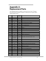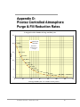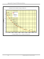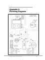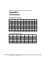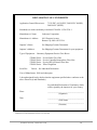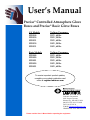
1
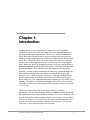
User’s Manual
Precise® Controlled Atmosphere Glove
Boxes and Precise® Basic Glove Boxes
CA Models
5220100
5220120
5220121
5220130
5220131
Voltage, Frequency
115V, 60 Hz
230V, 50 Hz
230V, 60 Hz
100V, 50 Hz
100V, 60 Hz
Basic Models
5220000
5220020
5220021
5220030
5220031
Voltage, Frequency
115V, 60 Hz
230V, 50 Hz
230V, 60 Hz
100V, 50 Hz
100V, 60 Hz
To receive important product updates,
complete your product registration card
online at register.labconco.com
Labconco Corporation
8811 Prospect Avenue
Kansas City, MO 64132-2696
800-821-5525, 816-333-8811
FAX 816-363-0130
E-MAIL [email protected]
HOME PAGE www.labconco.com
Please read the User’s Manual before operating the equipment.
Copyright © 2007, 2008 Labconco Corporation. All rights reserved.
The information contained in this manual and the accompanying products are copyrighted and all
rights reserved by Labconco Corporation. Labconco Corporation reserves the right to make periodic
design changes without obligation to notify any person or entity of such change.
Warranty
Labconco provides a warranty on all parts and factory workmanship. The warranty includes areas of
defective material and workmanship, provided such defect results from normal and proper use of the
equipment.
The warranty for all Labconco products will expire one year from date of installation or two years
from date of shipment from Labconco, whichever is sooner, except the following;
•
Purifier® Delta® Series Biological Safety Cabinets and PuriCare® Lab Animal Research
Stations carry a three-year warranty from date of installation or four years from date of
shipment from Labconco, whichever is sooner.
•
SteamScrubber® & FlaskScrubber® Glassware Washers carry a two-year warranty from
date of installation or three years from date of shipment from Labconco, whichever is
sooner.
•
Blood Drawing Chairs carry a ten year warranty.
•
Carts carry a lifetime warranty.
•
Glassware is not warranted from breakage when dropped or mishandled.
This limited warranty covers parts and labor, but not transportation and insurance charges. In the
event of a warranty claim, contact Labconco Corporation or the dealer who sold you the product. If
the cause is determined to be a manufacturing fault, the dealer or Labconco Corporation will repair
or replace all defective parts to restore the unit to operation. Under no circumstances shall Labconco
Corporation be liable for indirect, consequential, or special damages of any kind. This statement
may be altered by a specific published amendment. No individual has authorization to alter the
provisions of this warranty policy or its amendments. Lamps and filters are not covered by this
warranty. Damage due to corrosion or accidental breakage is not covered.
Returned or Damaged Goods
Do not return goods without the prior authorization from Labconco. Unauthorized returns will not be
accepted. If your shipment was damaged in transit, you must file a claim directly with the freight
carrier. Labconco Corporation and its dealers are not responsible for shipping damages.
The United States Interstate Commerce Commission rules require that claims be filed with the
delivery carrier within fifteen (15) days of delivery.
Limitation of Liability
The disposal and/or emission of substances used in connection with this equipment may be governed
by various federal, state, or local regulations. All users of this equipment are required to become
familiar with any regulations that apply in the user’s area concerning the dumping of waste materials
in or upon water, land, or air and to comply with such regulations. Labconco Corporation is held
harmless with respect to user’s compliance with such regulations.
Contacting Labconco Corporation
If you have questions that are not addressed in this manual, or if you need technical assistance, contact
Labconco’s Customer Service Department or Labconco’s Product Service Department at 1-800-8215525 or 1-816-333-8811, between the hours of 7:00 a.m. and 6:00 p.m., Central Standard Time.
Part #5233701, Rev. A
ECO E766
TABLE OF CONTENTS
CHAPTER 1: INTRODUCTION
1
CHAPTER 2: PREREQUISITES
Support, Vibration & Preventive Requirements
Location Requirements
Exhaust Requirements for the Pressure Relief Valve
Electrical Requirements
Plumbing Requirements for Gas, Vacuum, & Drying Train
Space Requirements
2
3
3
3
4
4
5
CHAPTER 3: GETTING STARTED
Unpacking the Glove Box
Installing the Glove Box on a Supporting Structure &
Work Surface
Connecting the Exhaust to the Pressure Relief Valve
Installation of Gloves to the Glove Ports
Connecting the Electrical Supply Source
Connect the Plumbing Lines for Gas, Vacuum & Drying Train
Validating the Glove Box
Oxygen Method Leak Testing Summary (ISO 10648-2)
Pressure Change Method Leak Testing Summary (ISO 10648-2)
6
7
7
8
13
13
14
20
22
23
CHAPTER 4: PERFORMANCE FEATURES AND
SAFETY PRECAUTIONS
Performance Features
Safety Precautions
24
24
27
CHAPTER 5: USING YOUR GLOVE BOX
Routine Daily Work Procedures
Hazardous Use with Chemicals
Prohibited Acid Use
29
29
31
31
CHAPTER 6: MAINTAINING YOUR GLOVE BOX
Routine Maintenance Schedule
Initial Certification
Recertification
Fluorescent Light Replacement
Pressure Relief Valve Replacement
Service Valve and Pressure Gauge Replacement
32
32
33
33
33
33
34
CHAPTER 7: ACCESSORIZING YOUR GLOVE BOX
35
CHAPTER 8: ELECTRICAL SYSTEM TROUBLESHOOTING
42
APPENDIX A: REPLACEMENT PARTS
43
APPENDIX B: DIMENSIONS
45
APPENDIX C: SPECIFICATIONS
46
APPENDIX D: PRECISE CONTROLLED ATMOSPHERE
PURGE & FILL REDUCTION RATES
47
APPENDIX E: LIFE SPAN FOR OXYGEN REMOVAL
COLUMN & MOISTURE TRAP REMOVAL
49
APPENDIX F: IONIZER FAN PERFORMANCE CRITERIA
51
APPENDIX G: HELIUM LEAK TEST METHOD
53
APPENDIX H: PLUMBING DIAMGRAMS
55
APPENDIX I: PRESSURE & FLOW RATE CONVERSIONS
57
APPENDIX J: REFERENCES
58
DECLARATION OF CONFORMITY
59
Chapter 1:
Introduction
Congratulations on your purchase of a Labconco Precise® Controlled
Atmosphere Glove Box or Precise® Basic Glove Box manufactured with a
one-piece molded polyethylene liner. The Precise Controlled Atmosphere
Glove Box comes equipped with six valves, pressure relief valve and two
chamber pressure gauge indicators, which are omitted from the Precise Basic
Glove Box. The Precise Basic Glove Box allows the end user to customize
the glove box to their application needs or use the glove box in its simplest
form. Both glove boxes are designed to provide an effective physical barrier
between the laboratory and the glove box interior. The barrier provides three
distinct advantages. First, it helps protect the technician from hazardous
materials. Second, it protects materials and laboratory equipment inside the
main chamber from the effects of exposure to ambient air, oxygen, and
moisture levels. Third, it provides a protective, leak-tight environment for
your research, testing, or production procedures; the leak rate of the glove
box is rated Class 1 for controlled atmosphere chambers per ISO 10648-2 test
methods. Each Precise Controlled Atmosphere Glove Box or Precise Basic
Glove Box is helium leak tested at the factory to ensure no leaks greater than
1 x 10⁻⁴ cc/sec.
The Precise Glove Boxes offer many unique features to enhance
performance. To take full advantage of them, you must read and understand
this manual and keep it handy for future reference. If you are unfamiliar with
how the Precise Glove Boxes operate, please review Chapter 4: Performance
Features and Safety Precautions before you begin working in the glove box.
Even if you are an experienced user, please review Chapter 5: Using Your
Glove Box so you can use the glove box efficiently.
Product Service 1-800-522-7658
1
Chapter 2:
Prerequisites
Before you install the glove box, you need to prepare your site for
installation. You must be certain that the area is level and of solid
construction. In addition, a dedicated source of electrical power should be
located near the installation site to power the glove box. Additionally, the
glove box should be strategically placed in the lab to provide efficient
workflow and prevent operator interference from normal traffic flow.
Carefully read this chapter to learn the requirements for your installation site:
•
The support, vibration and preventive requirements.
•
The location requirements.
•
The exhaust requirements for the pressure relief valve.
•
The electrical power requirements.
•
The plumbing requirements for gas, vacuum, and dry train.
•
The space requirements.
Refer to Appendix B: Precise Glove Box Dimensions for complete glove box
dimensions.
Refer to Appendix C: Precise Glove Box Specifications for complete
electrical and environmental conditions, specifications and requirements.
2
Product Service 1-800-522-7658
Chapter 2: Prerequisites
Support, Vibration and Preventive Requirements
In the preparation of a glove box site, please consider the following:
•
A bench or stand that is rigidly mounted to the floor or fixed to the wall,
but not both, may be appropriate. 35" to 40" (889mm to 1,016mm) is
typical for standing height (Labconco stands offered in Chapter 7 vary
from 33" to 40" or 838mm to 1,016mm).
•
The corners of a building typically have less vibration than the center,
which promotes analytical balance stability.
•
The bench typically should not contain any vibration-producing
equipment, such as shakers or pumps.
•
A marble slab with dampening pads placed within the enclosure is an
effective low cost means of controlling vibration for analytical balance
operation (see Chapter 7: Accessorizing Your Glove Box).
Location Requirements
The Precise Glove Boxes have been designed to rest on a typical 29"-30"
(737mm-762mm) deep work surface. The height should be 35"-40" for
standing position. Avoid placing the glove box in high traffic areas where
walking might disrupt the operator or experimentation.
Exhaust Requirements for the Pressure Relief
Valve
To prevent over or under pressurization of the main glove box chamber, the
Precise Controlled Atmosphere Glove Box includes a pressure relief valve
that activates at pressures and vacuums above +6" water gauge or below -6"
water gauge.
!
WARNING: The overpressurization of air at positive
pressure would allow any contaminants inside the glove
box to vent into the room. To control this venting into the
laboratory, Labconco offers three pressure relief valve
ventilation accessories. All three of these pressure relief
valve ventilation accessories are shown in detail in Chapter
3 and can be ordered from Chapter 7.
Please see Chapter 7 to order the pressure relief valve and other valve
accessories for the Precise Basic Glove Box.
Product Service 1-800-522-7658
3
Chapter 2: Prerequisites
The first option for venting the pressure relief valve is for ducting unfiltered
air to the outside via a 4" nominal diameter exhaust duct. The second and
third options for venting the pressure relief valve will add HEPA filters
and/or carbon filters to the exhaust duct and allow the vented air back into the
laboratory or to the outside. The HEPA filtered and carbon filtered pressure
relief vent kits may be combined if so desired. All pressure relief valve vent
kits include a 4" diameter thimble duct connection to aid in the connection to
the building exhaust blower preventing the pressure relief valve from
activating due to the negative pressure of the building exhaust. Labconco
offers accessory remote blowers listed in Chapter 7 for your convenience in
venting the pressure relief to the outside. These blowers have a 6" diameter
nominal inlet and a 4" x 6" duct transition is necessary to adapt from the 4"
diameter thimble connection provided with all relief valve kits.
!
WARNING: In the case of failure caused by excessive
vacuum within the main chamber, the user must safely
determine whether laboratory atmosphere entering the
glove box could result in fire, explosive hazard or damage
to property inside the glove box.
See Figures 3-1, 3-2, and 3-3 in Chapter 3 for ventilation connection
diagrams of the vent kits.
Electrical Requirements
Electrical receptacles should be located nearby for connecting the glove box,
or other optional laboratory equipment. The entire glove box is rated 115V,
8A or 230V, 4A or 100V, 8A. One duplex outlet is located inside the glove
box and is rated for 115V, 5A or 230V, 2A or 100V, 5A. Additional power
strip accessories are available and can be connected to the interior duplex
outlet (see Chapter 7).
Plumbing Requirements for Gas, Vacuum, and
Drying Train
The Precise Controlled Atmosphere Glove Box has four valves located on the
main glove box chamber and two valves located on the transfer chamber.
Two of the four valves on the main chamber should be used for the operation
of the main chamber gas inlet and vacuum outlet lines. To prevent
overpressurization, the gas inlet lines should be set at a pressure of 10-30 psi
through the use of a gas supply pressure regulator. The other two valves on
the main chamber can be used for connections to a recirculating drying train.
Drying trains are recirculating contaminate removal traps, powered by
vacuum pumps. They are used for the removal of oxygen and/or moisture
from the main chamber atmosphere. They can also be used to remove
organic vapors, acids, ammonia, or radioisotopes. See Chapter 7 for ordering
4
Product Service 1-800-522-7658
Chapter 2: Prerequisites
optional drying train removal traps. The two valves on the transfer chamber
are used for gas inlet and vacuum outlet lines. The transfer chamber lines can
be connected together with the main chamber gas inlet and vacuum outlet
lines to simplify gas and vacuum connections to both chambers. Illustrations
for all gas, vacuum, and recirculating drying trains are shown in Figures 3-5
through 3-10 in Chapter 3.
All valves utilize 3/8" (9.5mm) compression fittings or 3/8" (9.5mm) hose
barbs for soft tubing. Both styles are offered for your convenience.
Accessory gas and vacuum tubing kits are described in Chapter 7. Should
you require automatic chamber pressure controls, see Chapter 3 for details on
the accessory Pressure Controller and Chapter 7 for ordering information.
The Pressure Controller automatically monitors and controls pressures in
both the main chamber and transfer chamber; it also automates the operation
of purging and filling each chamber (gas outlet and gas inlet) up to 199
cycles. Consult your Safety Officer should you require ventilation and/or
filtration of the vacuum pump exhaust. Filtered exhaust (0.2 micron) and
contaminate removal traps are available for the vacuum pump (see Chapter
7). See Chapter 3 for typical installation of vacuum outlet and inert gas inlet
lines and Appendix H for plumbing diagrams.
See Chapter 7 to order any valves and/or pressure/vacuum gauges for the
Precise Basic Glove Box as these features have been omitted to enable the
end user customization.
Space Requirements
The dimensions are shown in Appendix B: Dimensions. Adequate space to
the right of the transfer chamber is required for loading and unloading.
Product Service 1-800-522-7658
5
Chapter 3:
Getting Started
Once the site for your glove box is properly prepared, you are ready to
unpack, inspect, install, and validate performance of your system. Read this
chapter to learn how to:
•
Unpack and move the glove box.
•
Set up the glove box with the proper supporting structure and work
surface.
•
Connect an exhaust system to the pressure relief valve (if applicable).
•
Install the gloves.
•
Connect the electrical supply.
•
Connect the plumbing lines for gas, vacuum, and drying train.
•
Validate performance of the glove box.
!
6
Each Precise Glove Box model weighs 185 lbs. each (83
kg). The shipping container allows for lifting with a
mechanical lift truck or floor jack. If you must lift the
glove box manually, follow safe-lifting guidelines. Do not
lift by the upper sheet metal façade and front panel as
damage can occur to the glove box liner.
Product Service 1-800-522-7658
Chapter 3: Getting Started
Lifting Instructions
Unpacking the Glove Box
We recommend that you do not remove the glove box from its shipping
container until it is ready to be placed into its final location. Move the unit
by placing a flat, low dolly under the shipping skid, or by using a floor jack.
Carefully remove the shrink-wrap and carton on the glove box and inspect it
for damage that may have occurred in transit. If damaged, notify the
delivery carrier immediately and retain the entire shipment intact for
inspection by the carrier.
)
THE UNITED STATES INTERSTATE COMMERCE
COMMISSION RULES REQUIRE THAT CLAIMS BE
FILED WITH THE DELIVERY CARRIER WITHIN
FIFTEEN (15) DAYS OF DELIVERY.
)
DO NOT RETURN GOODS WITHOUT THE PRIOR
AUTHORIZATION OF LABCONCO. UNAUTHORIZED
RETURNS WILL NOT BE ACCEPTED.
Product Service 1-800-522-7658
7
Chapter 3: Getting Started
)
IF ENCLOSURE WAS DAMAGED IN TRANSIT, YOU
MUST FILE A CLAIM DIRECTLY WITH THE FREIGHT
CARRIER. LABCONCO CORPORATION AND ITS
DEALERS ARE NOT RESPONSIBLE FOR SHIPPING
DAMAGES.
Do not discard the packing material until you have checked all of the
components and tested the glove box.
Installing the Glove Box on a Supporting
Structure and Work Surface
Exercise caution when lifting or moving the glove box.
When installing the glove box onto a work surface or benchtop, ensure that
the structure can safely support the combined weight of the glove box and
any related equipment. The work surface should be as wide as the entire
glove box to properly support it. The front of the glove box should be
aligned with the front of the work surface for optimal comfort. A height of
35"-40" (889mm-1016mm) is appropriate for standing operation. Labconco
base stands from Chapter 7 may be adjusted in height from 33"-40" (838mm1016mm).
Connecting the Exhaust to the Pressure Relief
Valve (If Applicable)
!
WARNING: The weight of the pressure relief exhaust
ductwork system must be supported independently of the
glove box superstructure or damage may occur.
The exhaust system should be installed by a qualified
HVAC contractor.
As stated in Chapter 2, the main chamber pressure relief valve is exhausted
back into the room unless an optional vent kit is installed. Figure B-1 in
Appendix B shows the location of the pressure relief valve without any
optional vent kits. Labconco provides pressure relief exhaust kits, which
exhaust to the outside. HEPA and/or carbon filtered exhaust kits are also
available. The HEPA and/or carbon filtered pressure relief exhaust kits also
provide thimble duct connections for exhausting the pressure relief valve to
the outside.
8
Product Service 1-800-522-7658
Chapter 3: Getting Started
To connect the Pressure Relief Vent Valve to an exterior exhaust system,
order the Ventilation Kit (#5242700) and refer to Figure 3-1. To provide
HEPA filtered exhaust to the room or outside, order the HEPA Filtered
Pressure Relief Vent Kit (#5238500) and refer to Figure 3-2. To provide
carbon filtered exhaust to the room or outside, order the Carbon Filtered
Pressure Relief Vent Kit (#5241200) and refer to Figure 3-3. The HEPA and
carbon filtered exhaust kits may be used together if required. All kits are
provided with full installation instructions, illustrations, and connections.
See Chapter 7, Accessories, to add a pressure relief valve (#5230600) to the
Precise Basic Glove Box. A 2.06" (52.3mm) diameter hole must be drilled
into the Precise Basic Glove Box shell. This hole is located on the 4.00"
(101.6mm) diameter x 1.00" (25.4mm) high raised boss; the raised boss is
located on the top of the glove box shell, in the front right side corner. Install
the pressure relief valve from the inside with the gasket in place and tighten
the retaining nut from the outside. After installation, the 2.00"-18 UNS
(50.8mm) diameter threads on the pressure relief valve should be exposed.
All vent kits attach to these threads as shown in Figures 3-1, 3-2, and 3-3.
Figure B-1 in Appendix B shows a top view of the exposed threads on the
pressure relief valve. A close up view of the pressure relief valve is shown
below.
Product Service 1-800-522-7658
9
Chapter 3: Getting Started
Figure 3-1
Pressure Relief Vent Kit (#5242700)
10
Product Service 1-800-522-7658
Chapter 3: Getting Started
Figure 3-2
HEPA Filtered Pressure Relief Vent Kit (#5238500)
Product Service 1-800-522-7658
11
Chapter 3: Getting Started
Figure 3-3
Carbon Filtered Pressure Relief Vent Kit (#5241200)
12
Product Service 1-800-522-7658
Chapter 3: Getting Started
Installation of Gloves to the Glove Ports
With the thumbs up and in a right/left orientation, secure the gloves in place
on the glove ports by stretching the beaded glove cuff into the glove port
groove nearest the window. Install the separate 8" diameter O-ring over the
gloves, into the outer groove of the glove port surface. Stainless steel band
clamps are provided for securing the separate O-ring into the glove port
groove. Replacement gloves and parts are listed in Chapter 7.
Figure 3-4
Glove Installation
Connecting the Electrical Supply Source to the
Glove Box
115V, 60 Hz; 100V, 50 Hz; or 100V, 60 Hz Models
Connect the power cord supplied to the IEC electrical supply plug located on
the back of the glove box. 115V or 100V models are rated at 8 amps total.
The maximum circuit load for the interior electrical duplex is 5 amps.
230V, 50 Hz or 230V, 60 Hz Models
The same procedure applies for the 230V international models except the
cords are shipped without an attached plug. Install the appropriate plug for
your electrical specifications per local codes. The 230V, 50 Hz or 230V, 60
Hz models are both rated at 4 amps total. The interior electrical duplex is
rated at 2 amps.
Product Service 1-800-522-7658
13
Chapter 3: Getting Started
Connect the Plumbing Lines for Gas, Vacuum,
and Drying Train
Labconco offers various vacuum and gas tubing installation kits listed in
Chapter 7 for connecting gas and vacuum line, or drying train to the glove
box. Refer to Figures 3-6, 3-7, 3-8, 3-9, and 3-10 that depict the installation
tubing kits. The primary connecting method involves the use of 3/8" O.D. x
3/16" I.D. tubing for gas and vacuum line connections; a tube support insert
must be placed inside the soft tubing to prevent the tube from disconnecting.
The alternative connecting method uses a tube connector and hose clamp
instead of a tube support insert. See Figure 3-5 (A and B) for both methods.
Consult Figure 3-8, which depicts typical tubing connections with the
accessory Automatic Pressure Controller. Vacuum pump model numbers can
be found in Chapter 7. Consult your Safety Officer to determine the
suitability and requirement for venting the exhaust port of a vacuum
pump to the outside. An accessory 0.2 micron filter can be installed in the
vacuum line to prevent particulate material contamination of the vacuum
pump. The 0.2 micron filter can also be installed in the inert gas supply line
connected to the main chamber and transfer chamber to insure a particulate
free gas supply (see Chapter 7). If required, other accessory chemical traps
can also be added to the vacuum line to prevent vacuum pump contamination
(see Chapter 7). Refer to Appendix H for typical plumbing diagrams.
14
Product Service 1-800-522-7658
Chapter 3: Getting Started
B
Hose Connector
Small Ferrule
Alternative
Method with
Hose Connector
Compression Nut
Note: Hose Clamp not
supplied.
A
Tube Insert
Large Ferrule
Small Ferrule
Primary
Method for
Tygon Tubing
Compression Nut
Figure 3-5
Close-up View of Typical Valve Connection Options
Product Service 1-800-522-7658
15
Chapter 3: Getting Started
Figure 3-6
Typical Tubing Connections for Manual Valve Operation
(Tubing Connection Kit 5245100 provides full details)
16
Product Service 1-800-522-7658
Chapter 3: Getting Started
Figure 3-7
Typical Tubing Connections with Automatic Pressure Controller
(Tubing Connection Kit 5245200 provides full details)
Product Service 1-800-522-7658
17
Chapter 3: Getting Started
Figure 3-8
Typical Connections Shown with Connection to the
Automatic Pressure Controller
(Full details provided with Automatic Pressure Controller)
18
Product Service 1-800-522-7658
Chapter 3: Getting Started
Figure 3-9
Typical Tubing Connections for Oxygen & Moisture
Removal Shown with the Automatic Pressure Controller
(Tubing Connection Kit 5242501 provides full details)
Product Service 1-800-522-7658
19
Chapter 3: Getting Started
Figure 3-10
Typical Tubing Connections for Dual Moisture/Solvent
Removal System Shown with the Automatic Pressure Controller
(Tubing Connection Kit 5242500 provides full details)
Validating the Glove Box
Each Precise Glove Box has been helium leak tested at the factory for
integrity and found to have no leaks greater than 1 x 10⁻⁴ cc/sec while at a
positive pressure of 5 inches helium. Refer to Chapter 6, Initial Certification
and Appendix G for Helium Leak Test Method.
Overall Glove Box Main Chamber Leak Test
The Precise Controlled Atmosphere Glove Box has been tested with an oxygen
monitor detecting oxygen levels as low as 1 ppm; the rate of increase in
oxygen over time was determined in accordance with the ISO 10648-2 oxygen
leak decay test method. The results validate that the Precise Controlled
Atmosphere Glove Box meets Class 1 conditions for controlled atmosphere
20
Product Service 1-800-522-7658
Chapter 3: Getting Started
chambers. Figure 3-11 shows test results of the oxygen decay or oxygen level
increase as a function of time. Per ISO specifications, Class 1 controlled
atmosphere chambers have a specified hourly leak rate of less than 5 x 10⁻⁴ per
Table 3-1 listed at the end of Chapter 3.
Precise CA Glove Box
Oxygen Decay Leak
ISO 10648-2 Test Method
140
Oxygen Decay
120
Barometic Pressure:
28.66 inches of Hg
100
Time Minutes
Main Chamber Temp.:
77.6° F
80
Main Chamber
Pressure: -4 inches
H2 O
60
Transfer Chambler
Pressure: 0 inches
inches Hg
40
Leak Rate Box 1.7 x
-4
10
Class 1 Leak Rate <= 5
-4
x 10
20
0
0
10
20
30
40
50
60
70
80
Oxygen ppm
Figure 3-11
The validation requirements and required testing instruments for all
applications shall be determined by the end user and Safety Officer. Other
validation test methods such as pressure leak decay tests may be conducted per
ISO 10648-2 standards. The pressure leak decay test may be performed, but
the pressure inside the glove box must be adjusted accurately for temperature
and barometric pressure.
These pressure leak decay tests are conducted under negative pressure of 250 Pa (-1" water gauge) for operational use or -1000 Pa (-4" water gauge)
for the acceptance test; the pressure leak decay tests are usually performed
under stable barometric pressure and temperature conditions to minimize the
effect of these variables.
A 0.1°C fall in temperature results in an equivalent pressure change of -34
Pa or -0.14 inches of water gauge. A 0.01 inches of mercury rise in
barometric pressure results in an equivalent pressure change of -34 Pa or
-0.14 inches of water gauge.
Product Service 1-800-522-7658
21
Chapter 3: Getting Started
Table 3-1
Classification of Glove Box Containment per ISO 10648-2
Class
Hourly Leak Rate (Tf)
1
2
≤ 5 x 10⁻⁴ hr-1
< 2.5 x 10⁻³ hr-1
3
4
< 10-2 hr-1
< 10-1 hr-1
Usage Example
Controlled atmosphere with high inert gas purity conditions
Controlled atmosphere under inert gas conditions or
permanently hazardous atmosphere
Permanently hazardous atmosphere
Atmosphere which could be hazardous
The required classification of leak tightness of each glove box must be
decided by the end user, their Safety Officer, and any oversight authorities.
Oxygen Method Leak Testing Summary (ISO 10648-2)
The method consists of measuring the increase in the oxygen concentration as
a function of time inside the glove box main chamber, previously purged with
an inert gas. The difference in the oxygen concentration between the end and
the beginning of the test, calculated on an hourly basis, gives the hourly leak
rate Tf:
Tf = 300 * (O2f –O2i) / (t * 106) where
O2f is the final oxygen concentration (ppm).
O2i is the initial oxygen concentration (ppm).
t is the duration of the test in minutes.
300 = 60 x 100/20 where 60 represents 60 minutes in an hour and 100/20
represents 20% oxygen in normal air.
Note: Use negative pressure of 1000 Pa (-4" water gauge) for acceptance test
and negative pressure of 250 Pa (-1" water gauge) for operational test.
22
Product Service 1-800-522-7658
Chapter 3: Getting Started
Pressure Change Leak Testing Method Summary
(ISO-10648-2)
The method consists of measuring the pressure rise per unit time after
establishing a negative pressure in the main chamber of the glove box. Use
-1000 Pa for the acceptance test and -250 Pa for the operational test. The
hourly leak rate includes adjustments for barometric pressure and temperature
changes which can be calculated as Tf:
Tf = (60/t) * ((PnT1/P1Tn) -1) where
t is the duration of the test in minutes.
P1 is the absolute pressure (ambient barometric pressure minus under
pressure) at the first reading in Pascals.
Pn is the absolute pressure (ambient barometric pressure minus under
pressure) at the last reading in Pascals.
T1 is the temperature at the first reading in Kelvin.
Tn is the temperature at the last reading in Kelvin.
60 represents 60 minutes in an hour.
T in Kelvin is equal to degrees Celsius + 273.
Product Service 1-800-522-7658
23
Chapter 4:
Performance Features and
Safety Precautions
Performance Features
The Precise Controlled Atmosphere Glove Box comes fully equipped with six
valves, pressure relief valve, and two pressure gauges. The Precise Controlled
Atmosphere Glove Box is designed to meet the needs of the laboratory scientists
requiring an inert atmosphere for sensitive ambient air operations. Labconco has
engineered the Precise Controlled Atmosphere Glove Boxes to meet the ISO
10648-2 Class 1 atmosphere leak specification. The Precise Controlled
Atmosphere Glove Box protects the technician from hazardous materials and
protects valuable laboratory materials from the effects of oxygen and moisture
exposure. The Precise Controlled Atmosphere Glove Boxes provide a leak tight
environment for manufacturing and chemical research procedures. The Precise
Basic Glove Box allows the end user to customize the glove box or use the glove
box in its simplest form. See Figure 4-1 to refer to a detailed description of the
Precise Controlled Atmosphere Glove Box main performance features.
1. Molded One-Piece Chemically-Resistant Glove Box Shell made of
medium density polyethylene, which provides superior chemical
resistance. The molded liner is seamless and easy to clean with coved
interior corners.
2. Six Manual Valves are installed on the controlled atmosphere glove box;
four on the main glove box chamber and two on the transfer chamber.
Two of the four valves on the main glove box chamber should be used for
vacuum purge and gas fill operations to develop an inert or controlled
atmosphere. The two valves on the transfer chamber are used to purge
and fill the transfer chamber, removing ambient air contaminants, and
preserving the controlled atmosphere within the main chamber when
transferring materials. The six valves can be installed separately on
Precise Basic Glove Boxes with modification to the glove box liner. See
Chapter 7 to order vacuum pumps and valve kits.
24
Product Service 1-800-522-7658
Chapter 4: Performance Features and Safety Precautions
Generally, 75-100 purge and fill cycles are required to reduce moisture
and oxygen levels below 1% (see Appendix D). 100-150 purge and fill
cycles will typically reduce moisture and oxygen levels to 0.3% or 3,000
ppm. After a 1% or less moisture and oxygen level is achieved, the other
two valves on the main chamber can be opened when they are connected
to a recirculating moisture and/or oxygen removal system. The
installation and operation of a removal system can further reduce and
maintain low moisture (<50 ppm) and oxygen (<5 ppm) levels. The
installation of the accessory Automatic Pressure Controller automates the
purge and fill process (up to 199 cycles). See Chapter 7 to order the
drying train removal accessories and the Automatic Pressure Controller.
3. Transfer Chamber Vacuum Gauge provides an indicator of vacuum
pressure in the transfer chamber. The indicator reads from 0 to 29 inches
of mercury vacuum. WARNING: A steel reinforced high vacuum
sleeve must be used with full vacuum.
Note: The Transfer Chamber Vacuum Gauge and High Vacuum Sleeve
are included on Precise Controlled Atmosphere Glove Boxes and can be
ordered from Chapter 7 for modification of Precise Basic Glove Boxes.
4. Main Chamber Pressure Gauge gives indication of main glove box
pressure. The gauge reads from -5 to +5 inches of water pressure.
Note: The Main Chamber Pressure Gauge is included on Precise
Controlled Atmosphere Glove Boxes and can be ordered from Chapter 7
for modification of Precise Basic Glove Boxes.
5. Glove Ports are 8" nominal size and molded into the main glove box
shell. The double grooves provide two points of glove restraint for
containment and safe changing of the gloves.
6. Neoprene Gloves are supplied with the glove box, .015" thick, 30" long,
one pair, size 9 ¾. See Appendix A for replacement parts and Chapter 7
for a description.
7. Removable Framed Glass Window is 1/4" thick laminated safety glass
and is reinforced with powder-coated steel frame. The removable glass
window frame provides access to the interior for loading large apparatus.
When removed, the window opening is 26.4" wide x 12.5" high (670mm
wide x 317mm high). The framed glass window is sealed with a onepiece molded neoprene gasket. See Chapter 7 for optional Acrylic
Viewing Window with Frame.
8. Fluorescent Lamp provides 30-40 foot candles of interior illumination
on the work surface. The lamp may be replaced from outside the glove
box. See Chapters 6 and 7 for replacement.
9. Control Panel consists of the main chamber pressure gauge, transfer
chamber vacuum gauge, and control switches for the light and duplex
outlet.
10. Work Surface is black chemically-resistant phenolic core and sealed to
the glove box floor. The black surface aids proper cleaning and provides
improved visibility of white powders. Phenolic core has superior
chemical resistance and stain resistance.
Product Service 1-800-522-7658
25
Chapter 4: Performance Features and Safety Precautions
11. Interior Switched Duplex is located on the glove box ceiling. The
innermost outlet of the duplex labeled “AUX” is controlled by the switch
located on the front control panel. The other outlet is on constantly when
the glove box is connected to an electrical supply. An accessory Electrical
Power Strip can be connected to the outlet to provide more electrical
receptacles (see Chapter 7). The interior duplex is rated at 115V, 5A or
230V, 2A or 100V, 5A.
12. Transfer Chamber Doors have a molded one-piece neoprene gasket with
a quick operating latch for user convenience. The counterweighted doors
swing up to save space. IMPORTANT: The transfer chamber must
have an optional High Vacuum Sleeve if the chamber is converted for
vacuum operation on Precise Basic Glove Boxes. See Chapter 7.
13. Pressure Relief Valve provides a safety relief for over or under
pressurization events within the glove box main chamber. The valve is set
to relieve positive or negative pressures above +6 or below -6 inches of
water gauge. The designed operational maximum limits for the Precise
Glove Box is +/-5 inches of water gauge. See Chapters 2, 3, and 7 for
exhausting properly. The pressure relief valve is included on Precise
Controlled Atmosphere Glove Boxes and can be ordered from Chapter 7
for modification of the Precise Basic Glove Boxes. See Chapter 3 for
modification instructions adding a Pressure Relief Valve to the Precise
Basic Glove Box.
Figure 4-1
Performance Features
(Precise Controlled Atmosphere Glove Box Shown)
26
Product Service 1-800-522-7658
Chapter 4: Performance Features and Safety Precautions
Safety Precautions
1. It is the responsibility of the user to determine the suitability of this
product for the intended applications. Consult your Safety Officer for
application review.
2. Although the glove box has been engineered to maintain optimum
operator safety, caution should always be used while working. Prior
to using the glove box, check to make sure that the main chamber
pressure is set for comfortable glove manipulation. Changes in glove
position will affect pressure in the glove box.
3. Use good housekeeping in the enclosure at all times. Clean up spills
immediately. Periodically clean enclosure interior per your standard
operating procedures for the specific chemicals in use.
4. This product is not designed or intended to be explosion proof. It is
the responsibility of the user to determine and avoid the lower
explosive limits and flammability of the enclosed gases used within
the controlled atmosphere glove box. The user is responsible for
taking proper precautions to prevent equipment damage or injury due
to an explosion or combustion of chemicals.
5. The use of flammable gases or solvents in the glove box should be
limited. Care must be taken to ensure against the concentration
buildup of flammable or explosive gases or vapors. Use of an open
flame or exposure to high heat should be avoided in the glove box as
the heat will damage the liner. DANGER: Use of added oxygen
inside the glove box must be avoided to prevent explosion, death,
or serious injury.
6. Perchloric acid use in this enclosure is prohibited.
7. Radioisotope material usage in the glove box should be approved by
your Safety Officer.
8. A qualified certification technician should test the glove box before it
is initially used.
9. The glove box should be recertified at least annually after installation.
10. The use of safety goggles, protective clothing, and any other personal
protective equipment recommended by your safety officer should be
observed.
11. The pressure relief valve provides protection from over or under
pressurization and should be filtered and/or ducted to the outside
if working with hazardous materials. Consult your Safety Officer.
When operating the transfer chamber gas inlet and vacuum outlet
valves, insure the inner transfer door is closed. Failure to do so can
result in the pressure relief valve opening, thereby, introducing
laboratory air into the glove box main chamber or glove box air into
the laboratory.
Product Service 1-800-522-7658
27
Chapter 4: Performance Features and Safety Precautions
12. All powders, gases, and particulates removed by the operation of
the vacuum pumps connected to this glove box are to be filtered
and/or ducted to the outside.
13. Exhaust vacuum pumps should be filtered and/or ducted to the
outside when using hazardous materials. Consult your Safety
Officer. Manipulations that generate gases or vapors from toxic
chemicals or radionuclides, must be evaluated carefully from the
standpoint of buildup to dangerous levels. The decontamination of
the glove box and compliance with applicable regulations is the
responsibility of the operator and safety officer. Venting or filtering
of vacuum pump exhaust is the operator’s responsibility.
14. Ensure that the glove box is connected to electrical service in
accordance with local and national electrical codes. Failure to do so
may create a fire or electrical hazard. Do not remove or service any
electrical components without first disconnecting the glove box from
electrical service.
15. Ensure only trained operators use the glove box. New users must
review the User’s Manual and become familiar with the operation of
the glove box.
16. Tag the glove box with appropriate warnings, if work inside the glove
box is hazardous or needs to remain untouched. Tag the glove box if
it requires servicing.
17. Consult your Safety Officer before removing any hoses to vacuum
pumps, gas lines, pressure gauges, or exhaust hoses; they may be
contaminated with chemicals used inside the glove box.
28
Product Service 1-800-522-7658
Chapter 5:
Using Your Glove Box
Now that the installation of your glove box is completed, you are ready to use
it.
Read this chapter to learn about:
•
Routine Daily Work Procedures.
•
Hazardous Use with Chemicals.
•
Prohibited Acid Use.
Routine Daily Work Procedures
Planning
•
Thoroughly understand procedures and equipment required before
beginning work. Work from a written plan.
•
Arrange for minimal disruptions, while the glove box is in use.
•
Consult your Safety Officer for personal protective equipment
recommendations and operating pressure confirmation.
Start-up
• Basic start-up procedure includes: turning on the vacuum pump,
opening the inert gas valve on the gas supply tank, and turning on the
glove box light.
Loading Materials and Drying Train Set-Up
•
Load only the materials and equipment required for the procedure.
Do not overload the glove box. When loading, ensure the inner door
is closed before opening the outer door. Then close the outer door.
Product Service 1-800-522-7658
29
Chapter 5: Using Your Glove Box
•
Perform purge and fill cycle on the transfer chamber using the
vacuum outlet and gas inlet valves. Depending on the vacuum level
achieved, it takes 1-5 cycles to reduce oxygen and moisture levels
below 1%. Porous materials being transferred may require longer
sustained vacuum purges to remove the oxygen and moisture trapped
in the materials.
•
After transferring materials to the main glove box chamber, perform
the required purge and fill cycles on the main chamber using the
vacuum outlet and gas inlet valves. To automate the purge and fill
cycles (1-199) for both glove box chambers, the addition of the
Automatic Pressure Controller (5238600 or 5238601) is
recommended (see Chapter 7). Normally 75-100 purge and fill cycles
will reduce moisture and oxygen levels below 1% (see Appendix D).
An additional 30-50 cycles will reduce moisture and oxygen levels
below 0.3% or 3,000 ppm. The use of external glove port caps will
expedite the purge and fill cycle times and help maintain low
moisture and oxygen levels when the glove box is not in use.
•
Maintaining a slight main chamber positive pressure can help to
preserve the glove box atmosphere. The moisture/oxygen permeation
rates are reduced at slightly positive pressures (see Appendix E).
•
Recirculating drying trains are required to further reduce and
maintain oxygen and moisture levels below 1%. Labconco oxygen
and moisture removal drying trains can maintain oxygen levels
below 5 ppm and moisture levels below 50 ppm.
•
Monitoring moisture and oxygen levels inside the glove box is
recommended by using accessory monitors (see Chapter 7).
Work Techniques
• Segregate all clean and contaminated materials in the work area.
•
Maintain work at a slightly negative pressure if working with
hazardous compounds.
•
Continuously run the recirculating oxygen and/or moisture drying
train to preserve the inert atmosphere if so desired.
Transferring Materials to the Outside
• All open chemical weigh vessels or containers must be sealed before
removing materials from the glove box main chamber.
•
30
Upon completion of work, the main glove box chamber must be
purged and filled approximately 5-10 times to remove airborne
contaminants from the work area. The exact number of cycles should
be determined by your Safety Officer.
Product Service 1-800-522-7658
Chapter 5: Using Your Glove Box
•
Objects in contact with previously contaminated internal atmospheres
must be surface decontaminated or bagged before removal from the
glove box through the transfer chamber.
•
After placing materials to be removed in the transfer chamber and
locking the internal door, the transfer chamber must be purged and
filled approximately 1-5 times depending on vacuum level achieved.
This ensures the removal of any remaining airborne contaminants
before the outer door is opened. Never apply a high vacuum purge on
sensitive electronic moisture and oxygen monitors. The exact number
of cycles should be determined by your Safety Officer.
Shutdown
•
To help preserve the controlled atmosphere, leave the glove box main
chamber under slightly positive pressure and continuously run the
recirculating drying train. The use of the accessory external glove port
caps can assist in preserving the inert atmosphere (see Appendix E).
•
Keep the outer door closed when not in use.
Hazardous Use with Chemicals
Hazardous chemicals may be used safely only when the glove box
vacuum pump and pressure relief valve are both properly vented and/or
filtered to the outside. Consult your Safety Officer for proper venting and
filtering of the vacuum pump exhaust and the pressure relief valve for your
application.
Prohibited Acid Use
Due to stainless steel components, the glove box interior must not be
exposed to mineral acid use. The glove box life span will be limited with use
of mineral acids.
NOTE: Labconco makes no claims about life span of the glove box with
mineral acid use and warranties will become void.
Product Service 1-800-522-7658
31
Chapter 6:
Maintaining Your Glove Box
Review this chapter on maintenance for the following:
1.
2.
3.
4.
5.
6.
Routine maintenance.
Initial certification.
Recertification.
Fluorescent light replacement.
Pressure relief valve replacement.
Service valve and pressure gauge replacement.
Routine Maintenance Schedule
Weekly
•
Wipe down the interior surfaces of the glove box with a disinfectant
or cleaner, depending upon the application.
•
Using an appropriate cleaner and cloth, clean the exterior surfaces of
the glove box, particularly the front and top, to remove any
accumulated dust.
•
Chart the pressure decay of the glove box, noting the change in
pressure over short time periods. Adjust as necessary for temperature
and barometric pressure changes. See Chapter 3: Validating the
Glove Box.
•
If required, monitor and record oxygen and moisture levels inside the
glove box with accessory monitors (see Chapter 7).
Annually
32
•
Replace the fluorescent lamp.
•
Have the glove box certified by a qualified technician. See
Certification and Recertification in Chapter 6.
Product Service 1-800-522-7658
Chapter 6: Maintaining Your Glove Box
Initial Certification
Each Precise Glove Box has been leak tested at the factory with helium gas at
positive 5" w.g. pressure; no leaks greater than 1 x 10⁻⁴ cc/sec are allowable.
The glove box should be certified by your Safety Officer before use, with one
of the two tests listed below under Recertification. See Appendix G for
Labconco Helium Leak Test Method performed on all glove boxes at the
factory.
Recertification
Under normal operating conditions, the glove box should be recertified at the
time of installation and at least annually thereafter. The certifier should
choose and perform one of the following tests. Refer to Validating the Glove
Box in Chapter 3.
•
•
Oxygen Method Leak Test per ISO 10648-2 test methods.
Pressure Change Leak Test per ISO 10648-2 test methods.
Fluorescent Light Replacement
1. Disconnect the power. Refer to Appendix A for replacement parts.
2. Locate the light reflector on the top of the glove box behind the front
panel.
3. Remove the light reflector support by removing two hex nuts located
on both sides of the light reflector.
4. Remove the old fluorescent lamp.
5. Reinstall the new fluorescent lamp and light reflector by reversing the
steps above.
Pressure Relief Valve Replacement
1. Decontaminate the glove box interior, if required.
2. Wear appropriate protective equipment as determined by your Safety
Officer.
3. Turn the glove box and vacuum pump OFF.
4. Disconnect the exhaust connection, if installed.
5. Loosen the large nut that secures the pressure relief valve.
6. Remove the pressure relief valve from the glove box interior.
Product Service 1-800-522-7658
33
Chapter 6: Maintaining Your Glove Box
7. Install the new pressure relief valve with the gasket to the inside.
Tighten the large nut.
8. Turn the glove box ON and re-certify the glove box.
9. Refer to Appendix A, Appendix B and Chapters 3 and 7 for
installation diagrams.
Service Valve and Pressure Gauge Replacement
1. Decontaminate the glove box interior, if required.
2. Wear appropriate protective equipment as determined by your Safety
Officer.
3. Turn the glove box and vacuum pump OFF.
4. Remove the valve or pressure gauge by loosening the large nut for the
valve or hardware for the pressure gauge. Remove the pressure hose
connected to the pressure gauge.
5. Replace with the new valve with the gasket inside or replace with the
new pressure gauge.
6. Tighten the large nut for the valve or the hardware for the pressure
gauge and re-attach the pressure hose to the pressure gauge.
7. Turn the glove box ON and re-certify.
8. Refer to Appendix A and Chapters 3 and 4 for installation diagrams.
34
Product Service 1-800-522-7658
Chapter 7:
Accessorizing Your Glove Box
There are many ways to accessorize and modify the controlled atmosphere
glove box for your individual requirements. These include many different
accessories listed in this chapter.
1. Black Epoxy Flat Work Surface (Part #4882807)
A solid epoxy resin 60" x 30" x 1.25" work surface is available to
support the glove box.
2. 30" Standard Base Cabinet (Part #9900200)
Two optional base cabinets can be ordered to support the 60" x 30"
work surface and glove box. Contact Labconco for additional sizes.
3. Adjustable Height Base Stands with Attached Work Surface
(Part #5235500 w/casters, Part #5235501 w/adjustable feet)
These stands, 60" x 31", with attached black laminate work surfaces
have an adjustable height range from 33" to 40" (838mm-1,016mm)
and include a lower shelf for supporting accessory equipment.
4. Anti-Static Ionizer Fan (Part #5234400, 100/115V or
Part #5234401, 230V International)
Used for weighing operations and attaches to the ceiling of the glove
box. The ionizer fan circulates ionized air inside the glove box to
reduce static charge. Ionizer Replacement Points (set of 8 emitter
electrodes) are ordered separately (Part #5235100). See Appendix F
for additional information.
5. Balance Vibration Isolator (Part #5234600)
Isolates building vibrations and aids with balance weighing. Includes
a 20" x 13" x 2 1/4" marble slab with four isolator pads and type 304
stainless steel top cover to protect the porous marble.
6. Valve Kits
The Precise Controlled Atmosphere Glove Box comes with six valves
already installed. The Add-A-Valve Kit #5225701 includes one
valve, O-ring, and nut for addition to the main chamber or the transfer
chamber. Identifier Label Set for valves (Part #5236600) is ordered
Product Service 1-800-522-7658
35
Chapter 7: Accessorizing Your Glove Box
separately. This kit can be used if additional valves are desired or
valves are added to the Precise Basic Glove Box. For a complete
installation of six valves, mounting brackets, pressure relief valve,
and labels for the Precise Basic Glove Box, order Full Valve Kit
#5232101. All valves require a 0.688" (17.5mm) diameter hole to be
drilled for mounting.
7. Vacuum Aspirator Kit
Includes the valve, hose, canister, and vacuum pump for evacuating
fluids around the work surface.
Part #
5241800
5241801
Descriptions
Vacuum Aspirator Kit, 115V
Vacuum Aspirator Kit, 230V International
8. Electrical Power Strips
These convenience electrical power strips are available in US and
international versions and plug into the interior duplex of the glove
box.
Part #
5211500
5210600
5290400
5332600
5211501
Descriptions
US Power Strip 115V, 4 Position, 5A
UK Power Strip 250V, 6 Position, 2A
European Power Strip 250V, 4 Position, 2A
Australian Power Strip 250V, 6 Position, 2A
Installation Tool
9. Electrical 9 Pin Sealed Pass-Through Kit (Part #5075619)
Includes sealed 9 pin (D-subminiature with male pins on one side and
female pins on the other) connector and cord for data transfer to a
typical printer outside the glove box from the balance. Note: Order
the 9 pin installation kit separately which includes all the drill bits and
hole saws for field installation (Part #5241100).
10. Remote Blowers and Dampers for Exhausting the Pressure Relief
Valve and/or Vacuum Pump
Has a 1/4 hp direct drive motor and corrosion-resistant epoxy-coated
steel housing and wheel with blower inlet of 6.00" ID. Outlet
dimensions are 4.25" x 7.38" OD. Dampers allow airflow adjustment
for blowers.
S.P.
CFM
Part #
4863500
4863501
3924000
4724200
36
0.0"
595
CFM @ Static Pressure-Inches of H2O
0.125"
0.25"
0.50"
0.75"
560
515
420
300
0.87"
167
Description
Remote Blower, 115 V, 60 Hz. 4.4 amps
Remote Blower, 115/230 V, 50 Hz, 5.6/2.8 amps International
6" Epoxy-Coated Steel In-Line Adjustable Damper
6" PVC In-Line Adjustable Damper
Product Service 1-800-522-7658
Chapter 7: Accessorizing Your Glove Box
Figure 7-1
All dimensions in inches
11. Pressure Relief Vent Kits and Pressure Relief Valve
Pressure relief vent kits are detailed in Chapters 2 and 3 and include
tubing connections and/or filters. Three pressure relief vent kits are
available to vent either unfiltered air or filtered air. All pressure relief
vent kits include a 3.9" (99mm) OD x 3.8" (97mm) ID nominal
thimble for connection to a house exhaust. The pressure relief valve
is factory installed on the Precise Controlled Atmosphere Glove Box,
but is an accessory on the Precise Basic Glove Box. See Chapter 3
for installation.
Part #
5242700
5238500
5241200
5230600
Descriptions
Pressure Relief Vent Kit (No Filters)
HEPA Filtered Pressure Relief Vent Kit
Carbon Filtered Pressure Relief Vent Kit
Pressure Relief Valve (Basic add on)
Vent Options
Outside
Room or Outside
Room or Outside
All
Vent Kits 5238500 and 5241200 may be used together if required.
12. Gas Inlet / Vacuum Outlet Tubing Kits and Direct Drive Vacuum
Pumps
These flexible vinyl tubing kits provide the necessary tubing and
fittings to make connections to an inert gas supply tank and a rotary
vane vacuum pump. See Figures 3-7 and 3-8.
Part #
5245100
5245200
1472100
7739400
7739402
Descriptions
Complete Gas/Vac Tubing Kit (Manual)
Complete Gas/Vac Tubing Kit (Auto)
Direct Drive Vacuum Pump, 115V, 50/60Hz
Direct Drive Vacuum Pump, 230V, 50/60Hz,
NEMA 6-15P plug
Direct Drive Vacuum Pump, 230V, 50/60Hz
with reverse IEC plug
Product Service 1-800-522-7658
Used With
Manual Valves
Pressure Controller
Both
Both, International
Version
Both, International
Version
37
Chapter 7: Accessorizing Your Glove Box
13. Automatic Pressure Controller
The Pressure Controller allows the end user the convenience of
automatically regulating pressure and vacuum within the glove box
main chamber and transfer chamber. The end user can also automate
the purge/fill cycles up to 199 cycles for each chamber. The vacuum
and pressure can be automatically regulated between -5 to +5 inches
of water gauge in the main chamber and between 0 to -29 inches of
mercury gauge in the transfer chamber. See illustration below and
figures in Chapter 3.
Part #
5238600
5238601
38
Descriptions
Pressure Controller 115V or 100V
Pressure Controller 230V International
Product Service 1-800-522-7658
Chapter 7: Accessorizing Your Glove Box
14. Filtration Components for Moisture, Oxygen and Fume Removal
The following components can be used to remove organics, acids,
ammonia, oxygen, moisture and other gases as indicated. They are
connected to the two auxiliary valves on the main glove box chamber
for recirculation of main chamber atmosphere and contaminant
removal of air (see Figures 3-9 and 3-10).
Part #
5248200
5248201
7815301
7815200
7814800
7815000
7995600
5244100
5244200
5244300
Descriptions
Vacuum Pump for Circulation, 115V, 60 Hz w/switch
Vacuum Pump for Circulation, 230V, 50 Hz International
Canister with Stand for Traps
Moisture & Solvent Trap Insert; to provide less than 50 ppm
moisture (molecular sieve)
Acid Vapor Trap Insert
Radioisotope Trap Insert
Ammonia Trap Insert
Flowmeter, Visual
Oxygen and Moisture Removal Column; to provide less than
5 ppm oxygen and less than 50 ppm moisture (refillable)
Oxygen and Moisture Removal Column Support Stand
15. Drying Train Tubing Kit
Includes the (FEP) tubing and connections required for connecting
typical drying train components such as moisture, oxygen, and other
gases. Fluorinated ethylene-propylene (FEP) tubing has very low
moisture absorption.
Part #
5242500
5242501
Descriptions
Drying Train Tubing Kit; moisture, solvents and
radioisotopes
Drying Train Tubing Kit; oxygen and moisture only
See Figures 3-9 and 3-10
16. Gas and Vacuum 0.2 Micron Filter (Part #5240100)
Used for removal of particulates in a drying train, vacuum pump
exhaust or inert gas line. 0.25"-0.38" ID tube connection with
additional fittings for attachment to 0.50" ID hose.
17. Oxygen Monitors
Oxygen monitors allow the user to continuously monitor oxygen
levels inside the glove box. All monitors are placed inside the main
chamber. Never operate a transfer chamber vacuum purge on
these sensitive oxygen monitors as damage can occur.
Part #
5244500
5244501
5244400
Descriptions
0-10,000 ppm Oxygen Monitor (with three ranges of 0-100 ppm, 1001,000 ppm, and 1,000-10,000 ppm) 100V/115V – 50/60 Hz
0-10,000 ppm Oxygen Monitor (with three ranges of 0-100 ppm, 1001,000 ppm, and 1,000-10,000 ppm) 230V – 50/60 Hz – International
0.1-100% Oxygen Monitor (1,000 ppm lowest) 100V/115V/230V –
50/60 Hz
Product Service 1-800-522-7658
39
Chapter 7: Accessorizing Your Glove Box
18. Moisture Monitors/Hygrometers
Moisture monitors or hygrometers allow the user to continuously monitor
moisture levels inside the glove box. All moisture monitors are placed
inside the main chamber. Never operate a transfer chamber vacuum
purge on these sensitive hygrometers as damage can occur.
Part #
5244900
5244901
5244800
Descriptions
1-1000 ppm Moisture Monitor/Hygrometer (Factory Set at
1-1,000 ppm, with three settings of 1-10 ppm, 1-100 ppm,
and 1-1,000 ppm) 100V/115V – 50/60 Hz
1-1000 ppm Moisture Monitor/Hygrometer (Factory Set at
1-1,000 ppm, with three settings of 1-10 ppm, 1-100 ppm,
and 1-1,000 ppm) 230V – 50/60 Hz – International
0-100% Hand Held Digital Hygrometer with Temperature
Display; measures relative humidity and temperature
19. External Glove Port Caps (Part #5242200)
Cap and clamp attaches to the glove ports to eliminate glove inflation
during purging and filling operations and reduce the cycle time of the
purging/filling process. Sold as a set of two.
20. Acrylic Viewing Window with Frame (Part #5236100)
Acrylic window, 1/2" thick, for those users that prefer acrylic over the
standard laminated safety glass (includes metal frame).
21. Guardian Jr.™Airflow Monitor (Part #5242000)
Audio and visual airflow monitor is especially useful for installations
that exhaust the pressure relief valve to the outside. Provides feedback
on the roof-mounted blower status. Monitor mounts to the top of the
control panel.
22. Interior Storage Shelf Kits
Provide convenient storage in the rear or the left side of the glove box
to maximize space. Additional hanging shelf kits (sold separately)
can hang from the rear interior shelf kit. Each shelf kit adds 240
square inches of usable space or an additional 25% of usable
space. Will support a large 15.2" x 4.8" x 3.7" tissue box.
Part #
5235000
5235001
Descriptions
Rear Storage Shelf Kit (w/four stainless shelves)
Side Storage Shelf Kit (w/four stainless shelves)
23. Hanging Shelf Kits
All shelves require the 5235000 rear interior storage shelf kit to
function.
Part #
3925000
3927700
3927800
5247300
5247301
40
Descriptions
Consists of three utility shelves
Bottle Holder
Tissue Holder (small tissue box)
Bin Organizer, 5.4" (plastic)
Bin Organizer, 7.4" (plastic)
Product Service 1-800-522-7658
Chapter 7: Accessorizing Your Glove Box
24. IV Bar Kit (Part #5242100)
Provides a bar for hanging IV bags or tools. Must be used with one of
the interior storage shelf kits (5235000 or 5235001).
25. Gloves (see Appendix A: Replacement Part numbers for other
glove sizes and material types)
Neoprene gloves are the most resistant to abrasion and tearing. Butyl
gloves provide higher impermeability and improved dexterity.
Hypalon gloves are made with a mixture of neoprene and butyl rubber
to provide an intermediate level of neoprene and butyl features.
26. Pressure Gauge for the Glove Box Main Chamber (Part #5237800)
Kit for the glove box main chamber is already installed on Precise
Controlled Atmosphere Glove Boxes. It can be added to the Precise
Basic Glove Boxes. Range -5" w.g. to +5" w.g. Kit includes the
pressure gauge, hose, and fittings for installation. Installing the
pressure gauge requires drilling a 0.562" (14.3mm) diameter hole in
the glove box ceiling.
27. Vacuum Gauge for the Transfer Chamber (Part #5237900)
Kit for the transfer chamber is already installed on Precise Controlled
Atmosphere Glove Boxes. It can be added to the Precise Basic Glove
Boxes. Range 0 to 29 inches of mercury vacuum. Kit includes the
vacuum gauge, hose, and fittings for installation. Installing the
vacuum gauge requires drilling a 0.562" (14.3mm) diameter hole in
the transfer chamber.
28. Transfer Chamber High Vacuum Sleeve (Part #5236200)
This sleeve is included on all Precise Controlled Atmosphere Glove
Boxes. An internal steel reinforced transfer chamber sleeve is
required if a vacuum will be pulled in the transfer chamber of the
Precise Basic Glove Box.
29. Exterior Transfer Chamber Shelf (Part #5245900)
A powder-coated steel shelf, 10.7" wide x 15.1" deep, can be attached
to the top of the transfer chamber. The exterior transfer chamber shelf
maximizes work area, useful for printers, laboratory supplies, and
notebooks.
Product Service 1-800-522-7658
41
Chapter 8:
Electrical System
Troubleshooting
Refer to the following table if your glove box fails to operate properly. If the
suggested corrective actions do not solve your problem, contact Labconco for
additional assistance. The Precise Controlled Atmosphere Glove Box and
Precise Basic Glove Box have only two electrical circuits.
PROBLEM
CAUSE
CORRECTIVE ACTION
Lights won’t operate.
Unit not plugged into outlet.
Plug unit into appropriate electrical service.
Circuit breaker(s) tripped.
Reset or replace circuit breaker.
Lamp not installed properly.
Inspect lamp installation.
Lamp wiring disconnected.
Inspect lamp wiring.
Defective lamp.
Replace lamp.
Light switch is defective.
Replace light switch.
Defective electronic ballast.
Unit not plugged in.
Replace ballast.
Plug unit into electrical service.
Circuit breaker(s) tripped.
Reset or replace circuit breaker.
Duplex switch is defective.
Replace duplex switch.
No power to duplex
electrical.
42
Product Service 1-800-522-7658
Appendix A:
Replacement Parts
The components that are available for your glove box are listed. The parts
shown are the most commonly requested. If other parts are required, please
contact Product Service.
Item
Qty.
Part
Number
1A
1B
2A
2B
2C
2D
2E
3A
3B
3C
3D
3E
3F
3G
3H
4
5
6A
6B
6C
6D
6E
6F
6G
6H
1ea
1ea
1ea
1ea
1ea
1ea
1ea
1pr
1pr
1pr
1pr
1pr
1pr
2ea
2ea
1ea
1ea
1ea
1ea
1ea
1ea
1ea
1ea
order by the foot
order by the foot
(25' coils)
1ea
1ea
1ea
1ea
1ea
1ea
1ea
1ea
1ea
1ea
1ea
1ea
1ea
1ea
1ea
4ea
1ea
REF.
REF.
1ea
5232200
5236100
1230700
1283900
5232900
5232901
5233400
1640600
1640601
1640602
1640500
1640501
1640502
1640000
1965600
5236200
1307000
5225701
1409900
1408300
1408400
1413602
1413500
1539500
7396209
Framed Glass Window (standard)
Framed Acrylic Window (optional)
Receptacle, 115V Duplex
Receptacle, 230V Duplex
Sealed Duplex, 115V Complete
Sealed Duplex, 230V Complete
Wallplate Duplex Gray
9 ¾ size Neoprene Gloves (standard)
9 ¾ size Butyl Gloves
9 ¾ size Hypalon Gloves
8 ½ size Neoprene Gloves
8 ½ size Butyl Gloves
8 ½ size Hypalon Gloves
O-Rings
Clamp – O-Ring Gloves
Transfer Chamber Inner Support Sleeve
Switch, Rocker (2 Position)
Valve Kit (included on CA)
Tube Support Insert
Large Ferrule
Small Ferrule
Stainless Compression Nut
Hose Connector (Secondary Method)
Polyvinyl Chloride Tubing 3/8" OD x 3/16" ID
FEP Tubing, Drying Train, 3/8" OD x 1/4" ID
1409901
1365200
1365300
5222700
5222800
5222801
5222802
5242900
1305800
1305900
5226400
5226500
5226401
5226501
1327204
1327205
1327200
5226900
5226901
5230600
Tubing Insert, Drying Train, 3/8" OD x 1/4" ID
Main Glove Box Pressure Gauge (included on CA)
Transfer Chamber Vacuum Gauge (included on CA)
Fluorescent Bulb, 8" Circleline FC8T9/CW, 22 Watt, 4 Pin
Ballast, 115V 60 Hz
Ballast, 230V 50 Hz (also used on 100V, 50 Hz)
Ballast, 230V 60 Hz (also used on 100V, 60 Hz)
Transformer, 230V to 100V (100V models only)
Inlet Power Cord, 115V
Inlet Power Cord, 230V
Inner Transfer Door w/attached gasket (Complete Assy.)
Outer Transfer Door w/attached gasket (Complete Assy.)
Inner Door w/attached gasket only
Outer Door w/attached gasket only
Circuit Breaker, 5A, 115V
Circuit Breaker, 2A, 230V
Circuit Breaker, 3A, 115V
Wiring Diagram, 115V
Wiring Diagram, 230V
Pressure Relief Valve (included on CA)
6I
7
8
9A
9B
9C
9D
9E
10A
10B
11A
11B
11C
11D
12A
12B
12C
13A
13B
14
Description
Product Service 1-800-522-7658
43
Appendix A: Replacement Parts
Figure A-1
Replacement Parts for Precise Glove Boxes
(Precise Controlled Atmosphere Glove Box Shown)
44
Product Service 1-800-522-7658
Appendix B:
Dimensions
See the following dimensions for all the glove boxes. Precise Controlled
Atmosphere shown. All dimensions in inches.
Figure B-1
Note: Six valves, pressure relief valve, and two pressure gauges are omitted on the
Precise Basic Glove Box.
Product Service 1-800-522-7658
45
Appendix C:
Specifications
This Appendix contains technical information about all the glove boxes
including electrical specifications and environmental operating conditions.
•
8 Amps, 115V or 4 Amps, 230V, 50/60 Hz or 8 Amps, 100V, 50/60 Hz,
Precise Glove Box.
Environmental Conditions
46
•
Indoor use only.
•
Maximum altitude: 6562 feet (2000 meters).
•
Ambient temperature range: 41° to 120°F (5° to 49°C).
•
Maximum relative humidity: 80% for temperatures up to 88°F (31°C),
decreasing linearly to 50% relative humidity at 104°F (40°C).
•
Main supply voltage fluctuations not to exceed ±10% of the nominal
voltage.
•
Transient over-voltages according to Installation Categories II (Overvoltage Categories per IEC 1010). Temporary voltage spikes on the
AC input line that may be as high as 1500V for 115V models and
2500V for 230V models are allowed.
•
Used in an environment of Pollution degrees 2 (i.e., where normally
only non-conductive atmospheres are present). Occasionally,
however, a temporary conductivity caused by condensation must be
expected, in accordance with IEC 664.
Product Service 1-800-522-7658
Appendix D:
Precise Controlled Atmosphere
Purge & Fill Reduction Rates
% Oxygen Level Per Number of Purge and Fill Cycles
25
Precise CA
Glove Box
1, 20.3%
20
Data Points =
Number of cycles,
% Oxygen
5, 18.1%
10, 15.1%
% Oxygen
15
15, 12.6%
20, 10.5%
10
25, 8.8%
30, 7.4%
35, 6.2%
40, 5.2%
45, 4.4%
5
54, 3.2% 70, 1.9%
78, 1.5%
88, 1.2%
105, 0.8%
125, 0.6%
0
0
20
40
60
80
100
120
# of Purge and Fill Cycles -5 to +5 Inches of water pressure
Product Service 1-800-522-7658
47
140
Appendix D: Purge & Fill Reduction Rates
% Moisture Level Per Number of Purge and Fill Cycles
25
1, 22.1%
Precise CA Glove
Box
20
Data Points =
Number of cycles,
% Water
% Moisture
5, 19%
10, 15.8%
15
15, 13.2%
20, 11%
10
25, 9.1%
30, 7.5%
35, 6.2%
42, 5%
5
54, 2.8%
70, 1.3%
78, 0.7%
0
0
10
20
30
40
50
60
70
80
# of Purge and Fill Cycles -5 to +5 Inches of water pressure
48
Product Service 1-800-522-7658
90
Appendix E:
Life Span for Oxygen Removal
Column & Moisture Trap Removal
Note: Precise Glove Box Volume is 13 cu. ft. or 368 liters; 3000ppm or 0.3% of 368 liters = 1.1 liters of oxygen initially used
Glove Box
Main Chamber Pressure
(inches of water)
-1
Oxygen Leak Rate
(ppm/min)
0.52
Initial Oxygen
Capacity Used
(ppm)
3000
Catalog# 5244200
Oxygen Column Life
(24 hour days)
21
Total Oxygen
Life Capacity
(ppm)
19022
0
0.22
3000
51
19022
1
0.15
3000
74
Glove Box
Main Chamber Pressure Moisture Leak Rate
(ppm/min)
(inches of water)
-1
2.9
0
1.7
Initial Moisture
(ppm)
10000
10000
7
1
19022
7
1
Note: All data with glove port covers installed
Catalog# 5244200
Total Moisture
Total Moisture
Number
Moisture Column Life
Life Capacity
Weight Capacity of Columns
(24 hour days)
(ppm)
(grams of moisture)
3318
13864241
100
1
5659
1
1.6
10000
6013
Note: 1ppm of moisture = 7.21ug of moisture inside the 368 liter glove box volume
Glove Box
Main Chamber Pressure Moisture Leak Rate
(inches of water)
(ppm/min)
-1
2.9
Total Oxygen
Number
Volume Capacity of Columns
(liters)
7
1
13864241
100
13864241
100
Note: All data with glove port covers installed
1
1
Initial Moisture
(ppm)
10000
Catalog# 7815200
Moisture Trap Life
(24 hour days)
4314
Total Moisture
Life Capacity
(ppm)
18023514
Total Moisture
Weight Capacity
(grams of moisture)
130
Number
of Traps
1
0
1.7
10000
7358
18023514
130
1
1
1.6
10000
7818
18023514
130
1
-1
2.9
10000
8630
36047028
260
2
0
1.7
10000
14721
36047028
260
2
1
1.6
10000
15641
Note: 1ppm of moisture = 7.21ug of moisture inside the 368 liter glove box volume
Product Service 1-800-522-7658
36047028
260
Note: All data with glove port covers installed
49
2
Appendix E: Life Span for Oxygen Removal Column & Moisture
Moisture/Oxygen Leak Rate @ -1, 0, +1 Box Pressure
400
Moisture -1
2.9 ppm/min
350
ppm Moisture/Oxygen
300
250
Moisture 0
1.7 ppm/min
200
Moisture +1
1.6 ppm/min
150
100
Oxygen -1
0.52ppm/min
50
Oxygen 0
0.22 ppm/min
Oxygen +1
0.15 ppm/min
0
0
10
20
30
40
50
60
70
Time (Minutes)
50
Product Service 1-800-522-7658
80
Appendix F:
Ionizer Fan Performance Criteria
Static Electricity Test
The tests were performed by monitoring the level of static electricity found on the work
surface and interior surfaces within the glove box. Static electricity levels were measured
with an AlphaLab Surface DC Voltmeter http://scientificmeter.com/surface_dc.htm.
A DESCO Emit Mini Zero Volt Ionizer http://www.descoemit.com/ViewProduct.aspx?pid=
50661&h=1323 was installed in the glove box. The DESCO ionizer is a dual steady state DC
auto balancing bench top ionizer. The ionizer helps to neutralize static electricity on
surrounding surfaces. The time required by the ionizer to neutralize static electricity will
be the shortest when objects are within 12" to 36" directly in front of the ionizer. The time
for neutralization increases as the distance from the ionizer increases. The time required
for sufficient electrostatic decay will also vary depending upon user application, moisture
levels within the supply air and the level of cleanliness within the glove box interior.
Product Service 1-800-522-7658
51
Appendix F: Ionizer Fan Performance Criteria
Electrostatic with
Glove Box Blower &
Ionizer Fan OFF
100 CFM Blower &
Ionizer Fan ON
After 1 Hour
100 CFM Blower &
Ionizer Fan ON
After 2 Hours
Test Point Locations and Voltage Levels
Metal
Back
Left
Right
Transfer
Interior
Interior
Interior
Chamber Surface
Surface
Surface
Handle
+ 734
+ 375
+ 106
+ 151
Metal
Housing
Inlet
HEPA
+ 420
Metal
Housing
Exhaust
HEPA
+ 220
+ 96
+ 114
+ 290
+ 93
+ 45
+ 28
+ 58
+ 51
- 52
- 15
Interior
Lamp
Window
Center
Work
Surface
+ 242
+ 153
+ 52
+ 46
+ 35
- 20
- 28
- 22
Static Electricity Test Results (VOLTS) on the Glove Box
(Neutralization is best between +/-100V)
The mini zero volt ionizer’s neutralization time will be shortest when objects are
approximately 12" to 36" directly in front of the ionizer and will increase as the
distance from the ionizer increases. Set the fan speed switch on the side of the
ionizer to the LOW or HIGH position. Higher airflow will result in faster
neutralization rates. Position the ionizer so that the maximum airflow is directed
at the items or area to be neutralized. The LED will turn on during power up and
remain GREEN during normal operation. The ionizer has a grounding jack and
must have a good earth ground to maintain proper balance. Always plug the AC
power adaptor into the ionizer and then into the appropriate AC power source.
The ionizer has no On/Off switch so it should be running as soon as it is plugged
in. The ionizer is designed to run off of 24VDC ±10% 300mA.
The balance adjustment for the ionizer can be accomplished by inserting a small
screwdriver or trimmer adjustment tool into the balance adjustment hole located
on the side of the unit. To increase the output in a positive direction, turn the
potentiometer in a clockwise direction. Conversely, to increase the output in a
negative direction, turn the potentiometer in a counter clockwise direction. It is
recommended that you use a surface DC voltmeter when adjusting the balance of
the ionizer.
Under normal conditions, the ionizer will attract dirt and dust (especially on the
emitter electrodes). To maintain optimum neutralization efficiency and operation,
cleaning with isopropyl alcohol should be performed on a regular basis. If the
performance of the ionizer degrades because of dirty or corroded points, the LED
on the front of the unit will turn YELLOW; the audible alarm will sound
continuously. Under this condition, the unit is not able to maintain balanced
ionization. The input power cord must be disconnected before the unit is opened
for maintenance. The emitter electrodes should be cleaned using the alcohol
cleaners included or a swab wet with isopropyl alcohol. Unscrew the 4 screws on
the back of the unit and then remove the screen. After cleaning the emitter
electrodes, reinstall the screen and 4 screws. The emitter electrodes should not
require replacement during the life of the unit with normal handling. Verify the
balance of the ionizer with a surface DC voltmeter after cleaning.
52
Product Service 1-800-522-7658
Appendix G:
Helium Leak Test Procedure
Purpose
The purpose of this test is to assure that all gasketed joints and seams of the
enclosure are helium leak tight.
Test Setup
1. Connect one of the valves to a vacuum pump.
2. Connect the other valve to a helium supply tank regulated between 10
and 15 PSI.
3. Install two neoprene gloves onto the glove ports using standard Orings and clamps.
4. For testing the Precise Basic Glove Box, a test fixture attaches to one
of the glove ports and replaces one of the gloves.
Test Procedure
1. Be sure the inner transfer chamber door is latched closed and the
outer door is open.
2. Open the helium inlet test valve and allow box to pressurize to +5
H2O gauge than close valve. Then with the vacuum pump running,
open the test outlet valve and allow the box to be evacuated to -5"
H2O gauge then close valve. Repeat this purge/fill for a total of three
cycles then close both valves.
3. While Glove Box pressure is held at +5.0" minimum, sniff all Glove
Box joints, seals and seams of the Glove Box shell using a test probe
connected to a helium mass spectrometer (Inficon model or equal
calibrated at 1.7 x 10⁻⁷ STD. CC/SEC). Also sniff the inner transfer
door seal by inserting test probe through the outer transfer chamber
door. Any detectable leaks greater than 1 x 10⁻⁴ STD.CC/SEC is
cause for rejection. Pressure relief valve is measured 1/2" away.
4. Close and latch the outer door and open the inner door. Adjust Glove
Box pressure to +5.0".
5. Sniff the outer transfer door seal and make sure there are no leaks
greater than rate specified in Step 3 above.
Product Service 1-800-522-7658
53
Appendix G: Helium Leak Test Procedure
Pressure Relief Valve Test Procedure
1. See that pressure relief valve opens when pressures and vacuum
exceed +/- 6" to 10" w.g. Record data. Check that valve reseals
within 2" w.g. of opening pressure and opening vacuum. Pressure
relief valve is standard on Precise Controlled Atmosphere Glove
Boxes.
Other Equipment
1. For a less critical helium leak measurement using a lower cost leak
detector, Labconco recommends using Restek (www.restek.com) or
other instrumentation available from a laboratory supply dealer.
54
Product Service 1-800-522-7658
Appendix H:
Plumbing Diagrams
Product Service 1-800-522-7658
55
Appendix H: Plumbing Diagrams
56
Product Service 1-800-522-7658
Appendix I:
Conversions
Pressure Conversions
To
From
mmHg
in.Hg
in.H2O
ft.H2O
atm
lb/in.2
Kg/cm2
kPa
bar
mmHg
in.Hg
in.H2O
ft.H2O
atm
lb/in.2
Kg/cm2
kPa
bar
1
25.40
1.868
22.42
760
51.71
735.6
7.500
750
.03937
1
.07355
.8826
29.92
2.036
28.96
.2953
29.53
.5353
13.60
1
12
406.8
27.69
393.7
4.016
401.6
.04461
1.133
.08333
1
33.90
2.307
32.81
.3347
33.47
.00132
.03342
.00246
.02950
1
.06805
.9678
.00987
.987
.01934
.4912
.03612
.4334
14.70
1
14.22
.1451
14.51
.00136
.03453
.00254
.03048
1.033
.07031
1
.0102
1.02
.1333
3.387
.2490
2.988
101.3
6.895
98.05
1
100
.0013
.0339
.0025
.0299
1.013
.0689
.981
.01
1
Flow Rate Conversions
To
From
lit/sec
gal/min
ft3/sec
ft3/min
bbl/hr
bbl/day
lit/sec
gal/min
ft3/sec
ft3/min
bbl/hr
bbl/day
1
0.06309
28.32
0.4719
0.04415
0.00184
15.85
1
448.8
7.481
0.6997
0.02917
0.03532
0.00223
1
0.01667
0.00156
6.50x10⁵
2.119
0.1337
60
1
0.09359
0.00390
22.66
1.429
641.1
10.69
1
0.04167
543.8
34.30
1.54x10⁴
256.5
24
1
Product Service 1-800-522-7658
57
Appendix J:
References
Many excellent reference texts and booklets are currently available. The
following is a brief listing:
Pharmaceutical Isolators, A Guide to their application design and control.
Pharmaceutical Press 2004, Editors: Midcalf, Phillips, Neiger, and Coles.
Isolation Technology, A Practical Guide, 2004 CRC Press, 2nd Edition,
www.crcpress.com
International Standard ISO 10648-2 Containment Enclosures
• Classification according to leak tightness and associated checking
methods.
NIOSH Pocket Guide to Chemical Hazards
U.S. Dept of Health and Human Resources
Centers for Disease Control and Prevention
National Institute for Occupational Safety and Health
58
Product Service 1-800-522-7658
DECLARATION OF CONFORMITY
Application Council Directive(s):
73/23/EEC, 89/336/EEC, 2002/95/EC (ROHS),
2002/96/EC (WEEE)
Standard(s) to which conformity is declared: EN61010-1, EN61326-1
Manufacturer’s Name:
Labconco Corporation
Manufacturer’s Address:
8811 Prospect Avenue
Kansas City, MO 64132 USA
Importer’s Name:
See Shipping/Customs Documents
Importer’s Address:
See Shipping/Customs Documents for your equipment
Type of Equipment: Laboratory Equipment Precise Glove Boxes
5220000 Series
5220100 Series
5220200 Series
5220300 Series
Serial No.:
Precise Basic Glove Box
Precise Controlled Atmosphere Glove Box
Precise HEPA-Filtered Glove Box
XPert Weigh Box
Various – See Individual Declaration
Year of Manufacture: 2006 and subsequent
I, the undersigned, hereby declare that the equipment specified above conforms to the
above Directive(s) and Standard(s).
See individual Declaration of Conformity which
will be signed by the importer for your country.
Place:
_______________________________________
(Signature)
Date:
_______________________________________
(Full Name)
_______________________________________
(Position)
Labconco P/N 36960-60 REV B, ECO E026
Product Service 1-800-522-7658
59