1
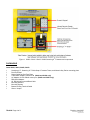
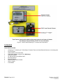
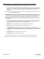
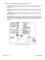
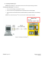
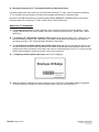
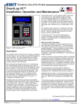
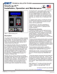
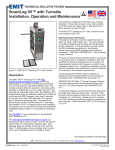
3
SmartLog X ™
Automated Personnel Grounding Verification
Wrist Strap and Footwear Tester
Automated ESD Record Keeping
Hardware Setup and Installation
3651 Walnut Ave, Chino, CA 91710
Phone: (909) 627-8178
Fax (909) 627-7449
DescoEMIT.com
TB-6552 Page 1 of 11
Revision June 2007
© 2007 DESCO INDUSTRIES INC.
Employee Owned
DESCRIPTION
The Desco EMIT SmartLog X3™ is designed for fast, frequent, and accurate testing of ESD personnel grounding
items. By depressing the electrode button once, the SmartLog X3™ tests the resistance path limits of the worn wrist
strap and both worn ESD footwear independently within three seconds. Test results are electronically stored in the
SmartLog X3™ and can easily be downloaded to a PC for logging records and evaluation. This product can be used
as one of the tools to fulfill the ANSI ESD S20.20 paragraph 6.1.3.2 “Compliance Verification Plan. Verification should
include routine checks of the Technical Requirements of the Plan.”
Paperless data can enhance operator accountability, immediately identifying problems while reducing logging and
auditing costs. There is no need to dedicate a computer. The SmartLog X3™ is a complete system including all
required components. Operator identification can be accomplished by using the keypad, swiping a barcode card, or
waving a proximity card (verify compatibility with the factory).
The SmartLog X3™ can test either single or dual-wire wrist straps; the split footplate design allows for individual
footwear testing all in one test. If a resistance path is below or exceeds the set limits, failure will be noted via an audio
and visual LED alarm. Passing tests can enable a relay for automated door openers. However, if the user desires to
test the wrist strap and ESD footwear separately, this can be accomplished. The wrist strap test is activated by
inserting wrist strap banana plug into the designated banana jack. Wrist strap only or footwear only testing can also be
accomplished. See Software Technical Bulletin TB-6547 for more information.
32 SmartLogs can be daisy-chained and connected to one computer, allowing data to be collected to one central
computer for all SmartLogs. The SmartLog X3™ can also be networked to a company's Intranet with the optional
50461 Ethernet Adapter. The SmartLog X3™ is calibrated to NIST traceable standards.
The SmartLog X3™’s default Wrist Strap test range is 1M – 10M Ohms, and the default Footwear test range is 1M –
35M Ohms. The ranges can be easily adjusted.
SmartLog X3™ Team Basic Software
Use the powerful versatile SmartLog X3™ Team Basic Software to collect and analyze records.
(1) Specify tests and shifts for each employee in database
(2) Auto or manual polling of data to computer
(3) Auto archive and network data posting
(4) Allow data to be saved and stored automatically
(5) Data retrieval at selectable time intervals
(6) Allow easy data analysis
See Technical Bulletin TB-6547 for more information.
ESD Association Information
“Compliance verification should be performed prior to each use (daily, shift change, etc.). The accumulation of
insulative materials may increase the foot grounder system resistance. If foot grounders are worn outside the ESD
protected area testing for functionality before reentry to the ESD protected area should be considered.” ESD SP9.2
APPENDIX B - Foot Grounder Usage Guidance
“A log should be maintained which verifies that personnel have tested their personal grounding devices. (ANSI/ESD
S20.20 Paragraph 6.2.2.2 Personnel Grounding Guidance)
ANSI/ESD S20.20 Table 1 Flooring-Footwear Systems Technical Requirements Recommended Range “less than 35 X
10E6 ohms measured per ESD STM 97.1”.
"Typical test programs recommend that wrist straps that are used daily should be tested daily. However, if the products
that are being produced are of such value that knowledge of a continuous, reliable ground is needed, and then
continuous monitoring should be considered or even required." (ESD Handbook TR 20.20 paragraph 5.3.2.4.4)
TB-6552 Page 2 of 11
Revision June 2007
© 2007 DESCO INDUSTRIES INC.
Employee Owned
Carefully unpack the Desco EMIT SmartLog X3™. The SmartLog X3™ comes ready to install without any changes to
the clock’s configuration.
If multiple SmartLogs are to be installed in a daisy-chain configuration, refer to page 9 for instructions.
Please see the following technical bulletins for more information on the SmartLog X3™
Number
TB-6502
TB-6546
TB-6547
Description
SmartLog X3™ Wrist Strap and Footwear Tester
Ethernet Adapter
SmartLog X3™ Team Basic Software
The Desco EMIT SmartLog X3™ is available in six models:
Item
50430
50431
50432
50433
50434
50435
Description
SmartLog X3™ 120V, Software Included
SmartLog X3™ 120V, Hardware Only
SmartLog X3™ 220V, Software Included
SmartLog X3™ 220V, Hardware Only
SmartLog X3™ 220V CE, Software Included
SmartLog X3™ 220V CE, Hardware Only
Note: SmartLog X3™ is not designed to work in high humidity environments above 70 RH%.
TB-6552 Page 3 of 11
Revision June 2007
© 2007 DESCO INDUSTRIES INC.
Employee Owned
Figure 1. 50430 / 50431 / 50432 / 50433 SmartLog X3™ features and components
PACKAGING
Items 50430, 50431, 50432, 50433
1
1
1
1
1
1
1
4
4
1
1
SmartLog X3™, SmartLog X3™ Wrist Strap / Footwear Tester, and Numeric Key Pad on mounting plate
Dual Foot Plate
Stereo Cable for Dual Foot Plate
Team Basic Software Version 4.99 (50430 and 50432 only)
AC Adapter 12VDC 500mA center pos. (50430 and 50431 only)
DB9 Serial Adapter
25’ RS-232 Non-inverted Data Cable
Mounting Anchors
Mounting Screws
Banana to Ring Terminal Cable
Shunt / Jumper
TB-6552 Page 4 of 11
Revision June 2007
© 2007 DESCO INDUSTRIES INC.
Employee Owned
Figure 2. 50434 / 50435 SmartLog X3™ features and components
PACKAGING
Items 50434 and 50435
1
1
1
1
1
1
4
4
1
1
1
SmartLog X3™, SmartLog X3™ Wrist Strap / Footwear Tester, and Laser Barcode Scanner on mounting plate
Dual Foot Plate
Stereo Cable for Dual Foot Plate
Team Basic Software Version 4.99 (50434 only)
DB9 Serial Adapter
25’ RS-232 Non-inverted Data Cable
Mounting Anchors
Mounting Screws
Banana to Ring Terminal Cable
Shunt / Jumper
Ferrite Bead
TB-6552 Page 5 of 11
Revision June 2007
© 2007 DESCO INDUSTRIES INC.
Employee Owned
CONFIGURING THE CLOCK, MOUNTING THE UNIT, AND CABLE CONNECTIONS
A. Clock’s Baud Rate, ID, Parity, Daylight Option and Port Expand (See Figure 3 on Page 7)
1. Plug the power supply into the unit and then to the appropriate AC source. Refer to Figure 3 to locate the
power input jack. The SmartLog X3™ will cycle through a self diagnostic program. The time and date will
appear on the screen when the diagnostics is complete. Do not continue until this step has been
completed.
NOTE: If any of the below settings are not correct, procedure to step 2 and press the Advance button until the
correct value appears on the display.
Power Requirement: It is highly recommended that these units are installed on power lines separate from
other devices. The clock should not be installed on the same power line with devices containing electric motors.
These units have a built-in self-healing fuse and surge, spike, and noise protection. The clock should be
powered on a dedicated electrical circuit. If you are located in an area where there are frequent electrical
storms, power surges, blackouts, or other similar problems, we strongly recommend that the unit be placed on
a surge protector.
2. After the self diagnosis press the MENU button six times. (If you do not press the Menu button within 20
seconds the clock will exit out of the set-up menu and will need to be reset by disconnecting then
reconnecting the power supply.) Refer to Figure 3 for button locations.
3. Baud Rate should be set at 9600 (factory default). Press Enter for the next screen.
4. Parity should be set for ODD (factory default). Press Enter for next screen.
5. The SmartLog X3™ ID is a 2 digit field with valid I.D. numbers 00 through 63. Each SmartLog X3™
should have a different I.D. number if they are connected to the same communication line. The SmartLog
X3™ should be numbered sequentially starting with 00, so that automatic polling in the software will not be
interrupted.
6. The Daylight Option is enables daylight savings in the clock.
7. Port Expand should be set to YES (factory default).
8. Press Enter button once more to cycle to the next setting before hitting the Menu button to exit.
NOTE: The setting will not change if you do not cycle to the next setting (by hitting the Enter button).
TB-6552 Page 6 of 11
Revision June 2007
© 2007 DESCO INDUSTRIES INC.
Employee Owned
B. Terminator Jumper, RS-485 Switch, RS-232 Switch and Relay Terminal
1. The Terminator Jumper should be applied only when the clocks are in a daisy-chain. It only needs to be
applied to the first and last SmartLog X3™ in the daisy-chain. A stand-alone SmartLog X3™ does not
need the jumper.
2. The RS-485 is set default on SLAVE position (right side) and does not need to be switched unless the unit
is in a daisy-chain. For units in a daisy-chain, set the RS-485 of the first SmartLog X3™ to MASTER (left
position).
3. The Relay Terminal connections can be made on the back of the SmartLog X3™ (See Figure 3). They
can be used to control doors, gates, etc. The relay terminal is limited to a maximum of 5A 250 VAC / 30
VDC and 10A 125 VAC.
4. The RS-232 Interface is described by the Electronic Industries Association (EIA) as EIA-232 or RS-232.
Special consideration should be used when installing the communications cable. Keep a 3 feet separation
distance from any EMF source (power wires, fluorescent lights, etc.) The cable length shall not exceed 50
feet from PC to unit. The Desco EMIT 50461 Ethernet Adapter should be used if distance requirements
exceed 50 feet.
Figure 3. Back-side of SmartLog X3™ plate
TB-6552 Page 7 of 11
Revision June 2007
© 2007 DESCO INDUSTRIES INC.
Employee Owned
C. Connecting the SmartLog X3™
NOTE: Both the SmartLog X3™ and computer should be turned off during the following procedures.
Connecting One SmartLog X3™ (See Figure 4)
1. Connect the Serial Adapter to the desired PC computer.
2. Connect one end of the provided RS-232 Non-inverted Data Cable to the Serial Adapter.
3. Connect the other end of the RS-232 Non-inverted Data Cable to port labeled “RS-232” on the SmartLog
X3™.
NOTE: Ensure that the SmartLog X3™ ID is set to 00 and its Terminator Jumper is left open.
Figure 4. Connecting one SmartLog X3™
TB-6552 Page 8 of 11
Revision June 2007
© 2007 DESCO INDUSTRIES INC.
Employee Owned
Connecting More Than One SmartLog X3™ (See Figure 5)
The following procedure provides an example on connecting 3 SmartLogs
1. Connect the Serial Adapter to the desired PC computer.
2. Connect one end of the provided RS-232 Non-inverted Data Cable to the Serial Adapter.
3. Connect the other end of the RS-232 Non-inverted Data Cable to clock port labeled “RS-232” on the
SmartLog X3™.
4. Apply a shunt across the 2 pin terminator jumper of the first SmartLog and set its ID to 00.
5. Connect one end of a RS-485 Inverted Data Cable to the clock port labeled “RS-485” on the first SmartLog
X3™.
6. Connect the other end of the RS-485 Inverted Data Cable to the clock port labeled “RS-485” on the
second SmartLog X3™.
7. Leave the terminator jumper of the second SmartLog X3™ open and set its ID to 01.
8. Connect one end of another RS-485 Inverted Data Cable to the clock port labeled “RS-485” on the second
SmartLog X3™.
9. Connect the other end of the same RS-485 Inverted Data Cable to the clock port labeled
“RS-485” on the third SmartLog X3™. (See NOTE)
10. Apply a shunt across the 2 pin terminator jumper of the third SmartLog X3™ and set its ID to 02.
(A jumper is only needed on the first and last units of the daisy-chain)
NOTE: An RJ11 splitter will be needed for connecting more than two units to a daisy-chain. The RJ11 splitter
attaches to the RS-485 clock port.
Figure 5. Connecting more than one SmartLog X3™
TB-6552 Page 9 of 11
Revision June 2007
© 2007 DESCO INDUSTRIES INC.
Employee Owned
D. Mounting the SmartLog X3™ and Optional 50443 Laser Barcode Scanner
Use the provided anchors and screws to mount the entire SmartLog X3™ plate. Be sure to place the SmartLog
X3™ at a height where all operators can clearly see the display and perform the necessary tests.
Mount the Laser Barcode Scanner to its proper location labeled “BARCODE SCANNER 50443” on the bottom
right-hand side of the SmartLog X3™ plate. (50430, 50431, 50432, 50433 only)
SMARTLOG X3™ HARDWARE
A. The Numeric Key Pad can be used to manually type in ID badge numbers if no card is available. To test
using the Numeric Key Pad, press CLEAR, enter an ID number, and press ENTER. (50430, 50431, 50432,
50433 only)
B. The SmartLog X3™ Wrist Strap / Footwear Tester’s default wrist strap test range is 1M – 10M Ohms. The
default footwear test range is 1M – 35M Ohms. The default test ranges may be changed to suit personal
ground device testing. See Technical Bulletin TB-6502 for instructions.
C. The Infrared Barcode Reader (50430, 50431, 50432, 50433 only) and optional Laser Barcode Scanner can
decode Code 39 (3 of 9) and Code 128 barcode. The location of the barcode on the employee card must be
placed a half inch from the bottom of the card to the center of the barcode (See Figure 5). To use the barcode
reader, follow the diagram located to the right of the clock’s vertical slot.
D. The Magstripe Reader (50434, 50435 only) reads Track 2 Magstripe.
Figure 6. Location of barcode on ID card
E. When the hardware installation has been completed, refer to TB-6129 for TEAM Basic Software installation.
TB-6129 will take you through the necessary steps to begin using your new SmartLog X3™.
TB-6552 Page 10 of 11
Revision June 2007
© 2007 DESCO INDUSTRIES INC.
Employee Owned
TROUBLESHOOTING
Problem: The host computer is not recognizing the SmartLog X3TM.
a. Verify that the cable from the computer to the SmartLog X3™ is properly connected. The cable should be flat
non-inverted (See Figure 4).
b. Verify that the communication setup on the clock is 9600 baud rate, parity ODD. Refer to the instructions on
back of SmartLog X3™ plate to enter configuration mode.
c. If there are more than 2 units, verify that their IDs are unique by entering the SmartLog X3™ configuration
mode.
d. Contact your local IT department to verify that the computer’s comport is working properly.
e. Make sure that the SmartLog X3™ LED’s are blinking during data transmission. If they are not blinking or
remain on all the time, please contact Desco EMIT technical support at (909) 627-8178 for further support.
CONTACT AND WARRANTY
USA
Desco EMIT
3651 Walnut Ave
Chino, CA 91710
Tel: (909) 627-8178
Fax: (909) 627-7449
Europe
Charleswater
Unit 17, Millbrook Business Park, Sybron Way
Crowborough, East Sussex, TN6 3JZ, U.K.
Tel: 01892 665313
Fax: 01892 668838
LIMITED WARRANTY
Desco EMIT expressly warrants that for a period of five (5) years from the date of purchase, Desco EMIT SmartLogs
will be free of defects in material (parts) and workmanship (labor). Within the warranty period, a credit for purchase of
replacement Desco EMIT products, or, at Desco EMIT's option, the product will be repaired or replaced free of charge.
If product credit is issued, the amount will be calculated by multiplying the unused portion of the expected five year life
times the original unit purchase price. Call our Customer Service Department at 909-627-8178 (Chino, CA) or 781821-8370 (Canton, MA) for a Return Material Authorization (RMA) and proper shipping instructions and address.
Please include a copy of your original packing slip, invoice, or other proof of date of purchase. Any unit under warranty
should be shipped prepaid to the Desco EMIT factory. Warranty replacements will take approximately two weeks.
If your unit is out of warranty, Desco EMIT will quote repair charges necessary to bring your unit up to Desco EMIT
factory standards. Call Customer Service at 909-627-8178 for proper shipping instructions and address. Ship your unit
freight prepaid.
WARRANTY EXCLUSIONS
THE FOREGOING EXPRESS WARRANTY IS MADE IN LIEU OF ALL OTHER PRODUCT WARRANTIES,
EXPRESSED AND IMPLIED, INCLUDING MERCHANTABILITY AND FITNESS FOR A PARTICULAR PURPOSE
WHICH ARE SPECIFICALLY DISCLAIMED. The express warranty will not apply to defects or damage due to
accidents, neglect, misuse, alterations, operator error, or failure to properly maintain, clean or repair products.
LIMIT OF LIABILITY
In no event will Desco EMIT or any seller be responsible or liable for any injury, loss or damage, direct or
consequential, arising out of the use of or the inability to use the product. Before using, users shall determine the
suitability of the product for their intended use, and users assume all risk and liability whatsoever in connection
therewith.
TB-6552 Page 11 of 11
Revision June 2007
© 2007 DESCO INDUSTRIES INC.
Employee Owned