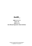
1
GMSplus User Manual Appendix Simple Interconnection Network GeoSIG Ltd, Wiesenstrasse 39, 8952 Schlieren, Switzerland Phone: + 41 44 810 2150, Fax: + 41 44 810 2350 [email protected], www.geosig.com GMSplus User Manual Appendix - Simple Interconnection Network 20.05.2015 / V1 2 / 11 Document Revision Version 1 Date 20.05.2015 Modification First release Prepared PAT Checked JON Released JON Disclaimer GeoSIG Ltd reserves the right to change the information contained in this document without notice. While the information contained herein is assumed to be accurate, GeoSIG Ltd. assumes no responsibility for any errors or omissions. Copyright Notice No part of this document may be reproduced without the prior written consent of GeoSIG Ltd The software described in this document is furnished under a license and may only be used or copied in accordance with the terms of such a license. Trademark All brand and product names mentioned are trademarks or registered trademarks of their respective holders. All rights reserved. GeoSIG Ltd. Switzerland GS_GMSplus_UserManual_App_ICC_V01.doc GMSplus User Manual Appendix - Simple Interconnection Network 20.05.2015 / V1 3 / 11 Table of Contents 1. Introduction ...................................................................................................................... 4 1.1. Common Timing ...................................................................................................................................... 4 1.1.1. Time Master Instrument ................................................................................................................... 4 1.1.2. Time Slave Instruments ................................................................................................................... 4 1.2. Common Trigger ..................................................................................................................................... 4 2. Installation ....................................................................................................................... 5 2.1. Overview ................................................................................................................................................. 5 2.2. Connection to the Instrument .................................................................................................................. 6 2.3. Connection to the Interconnection BUS .................................................................................................. 6 2.3.1. Cabling ............................................................................................................................................. 7 2.3.2. Earthing............................................................................................................................................ 7 2.3.3. Termination of the BUS ................................................................................................................... 7 2.3.4. Interconnection Cable ...................................................................................................................... 8 3. Configuration ................................................................................................................... 8 3.1. Common Time ......................................................................................................................................... 8 3.2. Common Trigger ................................................................................................................................... 10 Appendix A. Assembly Instructions for Cable Glands with Shield ..................................... 11 GS_GMSplus_UserManual_App_ICC_V01.doc GMSplus User Manual Appendix - Simple Interconnection Network 20.05.2015 / V1 4 / 11 1. Introduction If several instruments with internal or external sensors are placed on site, they can be interconnected with one cable while galvanically isolated from each other. For convenient cabling and advanced over voltage protection external junction boxes are supplied. The interconnection between the stations is carried out in a BUS topology. Distances between the two most far located stations can be as much as 1.3 km. This is a favourable and cost effective solution for many applications. a This Interconnection Network covers common time and common trigger only. In case data transfer should be handled over the interconnection network as well, please contact GeoSIG Ltd. 1.1. Common Time One of the interconnected instruments normally is connected to GPS or NTP for accurate timing (hereafter called Time Master Instrument). This instrument synchronise its internal clock to the GPS or NTP server and provides an accurate timing signal to all other instruments connected to the network (hereafter called Time Slave Instruments). 1.1.1. Time Master Instrument The Time Master Instrument can be any instrument in the BUS, so it does not have to be the first or last instrument in the chain. The Timing Master Instrument must be connected to a GPS or NTP server for accurate timing. Additionally this instrument must be configured as described in chapter 3.1. 1.1.2. Time Slave Instruments All the Time Slave Instruments synchronise their internal clock to the accurate time signal, distributed by the Time Master Instrument. These instruments within the network permanently check their synchronisation status. In case of not having the network time information available, the Time Slave Instruments use their internal clock. These instruments must be configured as described in chapter 3.1. 1.2. Common Trigger Triggering functionality of each recorder can be controlled using the configuration options ‘Be a source of network triggers’ and ‘Activate on network triggers’. By enabling or disabling these functionalities the behaviour of each instrument can be defined precisely as needed in the particular application. This functionality can be summarised as following, for detail settings see chapter 3.2: Be a source of network triggers: It can be selected if the instrument transmits an active trigger message to the network if an internal trigger condition is fulfilled. Activate on network triggers: It can be selected if the instrument triggers on an active trigger message arriving from the network. Record on network triggers only: It can be selected if the instrument should record on network triggers only and ignore all internal triggers. GS_GMSplus_UserManual_App_ICC_V01.doc GMSplus User Manual Appendix - Simple Interconnection Network 20.05.2015 / V1 5 / 11 2. Installation 2.1. Overview The Interconnection Junction Boxes are supplied in order to facilitate on-site wiring. Since these networks can extend over hundreds of meters involving long cables the Interconnection Junction Box provides additionally advanced protection against over-voltages, such as electrostatic discharges and lightning, and differences in local earth potentials. The protection is realised in the following ways. Advanced Lightning and over-voltage protection is implemented in the Interconnection Junction Box. An interconnection option board which takes care of the galvanic isolation is installed in the instruments. Figure 1 shows the Interconnection Junction Box which is used along with each recorder. Figure 1. Interconnection Junction Box (150 x 150 x 80 mm) The interconnection wiring is site-specific and normally carried out by the customer. In order to achieve a maximum protection and system reliability, a couple of important points regarding shielding and earth must be taken care of during installation. This is mainly in relation with earth and cable shield connections and described in the following chapters. GS_GMSplus_UserManual_App_ICC_V01.doc GMSplus User Manual Appendix - Simple Interconnection Network 20.05.2015 / V1 6 / 11 2.2. Connection to the Instrument The instrument is connected to the Interconnection Junction Box over the INTERCON connector on the front of the instrument. The related cable with a length of approximately 2 m is already mounted on the Interconnection Junction Box and can be easily plugged to the instrument. It’s important that both – the instrument and the junction box – are connected to local earth. There is an earth screw on the Interconnection Junction Box and the base plate of the instrument which can be used for this purpose. The earth cable should be connected first to the Interconnection Junction Box and then wired to the instrument. See Figure 2 for details. GMSplus OPTION “Interconnection” INTERCON plug To the previous instrument Junction Box To the next instrument Cable shield Cable shield Local ProtectionEarth Figure 2. Wiring, including Interconnection Junction Box 2.3. Connection to the Interconnection BUS Each instrument is connected to the BUS cable via the Interconnection Junction Box as described in chapter 2.2. The setup looks as shown below: Last Instrument N Instruments between First Instrument GPS Termination Termination Figure 3. Interconnection BUS GS_GMSplus_UserManual_App_ICC_V01.doc GMSplus User Manual Appendix - Simple Interconnection Network 20.05.2015 / V1 7 / 11 2.3.1. Cabling The cable coming from the previous Interconnection Junction Box and the cable going to the next one are connected as indicated below. Terminator, see chapter 2.3.3 To the instrument BUS to previous Junction Box 8 7 6 5 4 3 21 See Appendix A BUS to next Junction Box 8 7 6 5 4 3 21 Cable shields from the BUS Figure 4. Connectors inside Junction Box Pin 1st Box 1 ----------2 ----------3 ----------4 ----------7 ----------- Function 2nd Box 1 ----------2 ----------3 ----------4 ----------7 ----------- n Box 1 ----2 ----3 ----4 ----7 ----- Trigger + (RS-485) Trigger - (RS-485) Time + (RS-485) Time (RS-485) GND (optional) No crossing of the cables is needed at any place. The wire from Pin 1 will always go to the Pin 1 of the next Interconnection Junction Box. Pin 2 to Pin 2 and so on… 2.3.2. Earthing All Interconnection Junction Boxes and Instruments must be properly connected to the local earth. Figure 5. Bus cabling The cable shield must be connected to the earth on one location only to avoid a ground loop on the cable. Therefore inside all Interconnection Junction Boxes the cable shield must be connected to the provided cable socket with one exception: In one (1!) Interconnection Junction Box the cable shield must be connected to the housing as described in Appendix A. For all others use the internal cable socket. For details see Figure 5 on the right side. 2.3.3. Termination of the BUS Figure 6. Terminal plug In the first and the last Interconnection Junction Box on the BUS a terminal plug (see Figure 6) must be connected to the free connector. See also blue boxes in Figure 5 on the right side. The terminal plug is terminated with resistors between pins 1-2 and 3-4 according to the impedance of the interconnection cable. As standard 120 Ohm resistors are provided. GS_GMSplus_UserManual_App_ICC_V01.doc GMSplus User Manual Appendix - Simple Interconnection Network 20.05.2015 / V1 8 / 11 2.3.4. Interconnection Cable The appropriate choice of the interconnection cable is important for the functionality of the network. For all network types the cable has to have twisted-pairs and a shield in order to prevent it from picking up interference. The cable glands of the interconnection box support cables with diameter between 5 and 6.5 mm. Another important aspect is the diameter of the conductor required which is a trade off between total length of the bus network and the conductor diameter. Maximum total cable resistance (both ways) is 2 * 50 Ohm. Table 1 shows the relationship between cable cross-sections and maximum network lengths. Table 1. Cable cross-sections vs. maximum network length Cross-section Resistance Maximum network length [mm2] [Ohm/km] [m] 0.20 89.0 500 0.25 71.2 700 0.35 50.9 900 0.5 36.6 1300 A way to reduce the cable resistance is to connect two pairs in parallel. This effectively reduces the resistance by factor two and doubles the maximum length. a In case if the interconnection network is planned to be longer than 1300 m please contact GeoSIG for assistance. 3. Configuration The instrument must be set up according to the GMSplus User Manual so that the communication is established and parameters can be changed. The following chapters just guide through the settings in relation with the interconnection network. For any other adjustments consult the GMSplus User Manual. 3.1. Common Time Press ‘O’ to select the Miscellaneous Parameters menu. Main A) B) C) D) E) F) G) H) I) K) M) N) O) Menu Station description ............. Station code .................... Location description ............ Seismic network code ............ Number of Channels .............. Number of Output Streams ........ Number of Trigger Sets .......... Number of Preset Triggers ...... Channel Parameters .............. Trigger Parameters .............. File Storage and Policy ......... Communication Parameters ........ Miscellaneous Parameters ........ GMSplus - GeoSIG Ltd GSGMS Switzerland GS 3 0 2 0 -> -> -> -> -> Then press ‘K’ to get to the Time synchronisation menu to adjust the settings of the time synchronisation. GS_GMSplus_UserManual_App_ICC_V01.doc GMSplus User Manual Appendix - Simple Interconnection Network 20.05.2015 / V1 Main A) B) C) D) E) H) I) J) K) L) M) N) Menu | Miscellaneous Offset detection time, sec ............... Offset correction time, sec .............. Offset correction counts ................. MiniSEED record length ................... Extended MiniSEED format ................. State of health .......................... Test configuration ....................... Messaging and debugging .................. Time synchronization ..................... Instrument configuration options ......... Time for sending daily logfile, hour ..... Time for sending daily logfile, minute ... 9 / 11 10 (0x0A) 5 (0x05) 1 (0x01) 512 Yes -> -> -> -> -> 0 (0x00) 0 (0x00) The following menu appears: Main A) M) N) Q) Menu | Miscellaneous | Time Synchronization Time source ................................ RTC watchdog timeout, sec .................. Send SOH upon RTC status change ............ Offset to UTC, minutes ..................... RTC 1200 (0x4B0) No 0 (0x00) Adjust the following parameter by pressing ‘A’: Time source RTC Internal clock is not synchronizing itself to any source GPS Internal clock is synchronizing to the connected GPS NTP Internal clock is synchronizing to a NTP server AUTO Internal clock synchronizes to NTP in case GPS is not available NET1PPS Internal clock is synchronizing to the time signal distributed by the Time Master Instrument over the interconnection network. Instrument acts as Time Master Instrument Instrument acts as Time Slave Instrument a Make sure that only one instrument in the interconnection network is configured as Time Master Instrument. All others must be configured as Time Slave Instruments. GS_GMSplus_UserManual_App_ICC_V01.doc GMSplus User Manual Appendix - Simple Interconnection Network 20.05.2015 / V1 10 / 11 3.2. Common Trigger Press ‘G’ to select the Number of Trigger Sets and make sure that there is at minimum one trigger set Main A) B) C) D) E) F) G) H) I) K) M) N) O) Menu Station description ............. Station code .................... Location description ............ Seismic network code ............ Number of Channels .............. Number of Output Streams ........ Number of Trigger Sets .......... Number of Preset Triggers ...... Channel Parameters .............. Trigger Parameters .............. File Storage and Policy ......... Communication Parameters ........ Miscellaneous Parameters ........ GMSplus - GeoSIG Ltd GSGMS Switzerland GS 3 0 2 0 -> -> -> -> -> Press ‘K’ to get to the Trigger Parameters menu to adjust the settings of the triggers. The following menu appears. In case the number of trigger sets is set to ‘0’ this menu can not be selected. Main A) B) C) G) H) I) J) K) L) M) N) O) P) Q) R) T) Menu | Triggerset 1 of 2 Triggerset name ....................................... Event recording ....................................... Record on network triggers only ....................... Pre-Event, seconds .................................... Post-Event, seconds ................................... Trigger time frame, sec ............................... Max. event duration, sec .............................. Monitored channels .................................... Trigger settings ...................................... Stored channels ....................................... List of stored channels ............................... Be a source of network triggers (received from LAN) ... Activate on network triggers (received from LAN) ...... Be a source of network triggers (Interconnection) ..... Activate on network triggers (Interconnection) ........ Event processing ...................................... Trigger1 Yes No 5 (0x05) 10 (0x0A) 3 (0x03) 60 (0x3C) 3 -> 3 -> No No Yes Yes None Adjust the following parameters according to your set up by pressing ‘Q’ or ‘R’ : Be a source of network triggers (Interconnection) Yes Activate on network triggers (Interconnection) Yes No No It can be selected, if all the other instruments in the interconnection network should be alerted in case of a local trigger. It can be selected if the instrument should trigger in case it will be alerted over the interconnection network from any other instrument. a Each trigger set can be adjusted according to your wishes. To change the trigger set press ‘+’ or ‘-‘. GS_GMSplus_UserManual_App_ICC_V01.doc GMSplus User Manual Appendix - Simple Interconnection Network 20.05.2015 / V1 11 / 11 Appendix A. Assembly Instructions for Cable Glands with Shield a The cable shield should be connected to the housing on one (1!) Interconnection Junction Box only. For all others the internal cable socket must be used. The cable glands of the interconnection box support cables with diameter between 5 and 6.5 mm. GS_GMSplus_UserManual_App_ICC_V01.doc