1
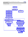
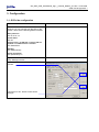
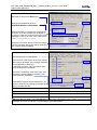
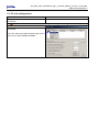
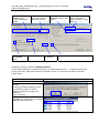
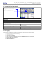
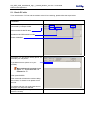
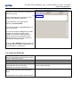
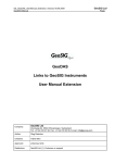
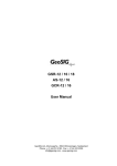
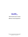
GCR-16 with internal modem
GXR user manual appendix J
GeoSIG Ltd, Ahornweg 5a, 5504 Othmarsingen, Switzerland
Phone: + 41 44 810 2150, Fax: + 41 44 810 2350
[email protected], www.geosig.com
GS_GSR_GCR_UserManual_App_J_internal_Modem_V01.doc / 18.09.2009
GXR manual appendix J
ii
Document Revision
Author
Checked
Approved
STT
SER, RIA
MAE
Version
17.03.2009
14.04.2009
Action
First version, draft
Release
Disclaimer
GeoSIG Ltd reserves the right to change the information contained in this document without notice. While the information contained
herein is assumed to be accurate, GeoSIG Ltd assumes no responsibility for any errors or omissions.
Copyright Notice
No part of this document may be reproduced without the prior written consent of GeoSIG Ltd. The software described in this document
is furnished under a license and may only be used or copied in accordance with the terms of such a license.
Trademark
All brand and product names mentioned are trademarks or registered trademarks of their respective holders.
All rights reserved.
GeoSIG Ltd
Switzerland
GS_GSR_GCR_UserManual_App_J_internal_Modem_V01.doc / 18.09.2009
GXR manual appendix J
iii
Table of Contents
1. Introduction...................................................................................................................... 4
2. Preparations .................................................................................................................... 4
2.1. On/Off switch...........................................................................................................................................4
2.2. Process overview ....................................................................................................................................5
3. Configuration ................................................................................................................... 6
3.1. GCR side configuration ...........................................................................................................................6
3.2. PC side configuration ..............................................................................................................................8
4. Connect to the instrument.............................................................................................. 10
5. Debugging ..................................................................................................................... 10
5.1. Check PC side.......................................................................................................................................11
5.2. Check the GCR side .............................................................................................................................12
GS_GSR_GCR_UserManual_App_J_internal_Modem_V01.doc / 18.09.2009
GXR manual appendix J
4
1. Introduction
a
Dear Valued GeoSIG Customer, thank you for purchasing this product.
These Instruments have been optimised to meet the requirements of the majority of customers
out of the box and may have even be delivered tailored to your needs. In any case, to be able
to get the most out of our product, please carefully study this manual, its appendices and
referenced manuals, as well as any other documents delivered with it.
This is a reliable and easy to use device, and at the same time a sophisticated product, which
requires care, attention and know-how in configuring, installing, operating and maintenance.
This manual describes the setup of the GCR-16 with internal modem step by step. It is based on the
standard GXR User manual. It is highly recommended to read the GXR user manual before starting with this
appendix.
The GCR-16 with internal modem has the following two new options:
• Send text messages (SMS) on event to two different numbers.
• On/Off button from the outside of the GCR-16.
2. Preparations
Before you start to configure and install the GCR-16 please ensure that the following material is ready:
•
•
•
•
•
•
Running GeoSIG instrument (GCR-16)
GSM modem (SIEMENS TC-35) inside the GCR-16
Valid SIM card with GSM Data mode activated (to be checked with provider)
Latest GeoDAS software
GeoSIG RS-232 cable
Fully operational Analog or GSM modem for computer side (in- or external)
Now please ensure that the following points are done:
•
•
•
•
SIM card pin code is disabled
Antenna is connected to the instrument
Sensor is connected to the instrument
The GMS modem inside the GCR-16 has got three cables attached (power, antenna and RS-232)
2.1. On/Off switch
There are two on/off switches, one inside of the housing, another one outside of the housing. It is important
to know that they are parallel to each other. This means that if the inside switch is turned on, you can not
turn the instrument off from the outside. This a security so it can be avoided that the instrument is turned off
from the outside by accident.
The following table shows the logic:
Switch inside
Switch outside
GCR
On
On
On
On
Off
On
Off
On
On
Off
Off
Off
GS_GSR_GCR_UserManual_App_J_internal_Modem_V01.doc / 18.09.2009
GXR manual appendix J
5
2.2. Process overview
The following chart shows the process how to install a GCR-16 with an internal modem.
Start GCR
Yes
No
Modem blinking?
GCR-16 starts?
Check cables,
Contact GeoSIG
Plug RS-232 cable
Configure GCR
Plug out RS-232 cable
Restart the GCR
Send text message on event
Yes
Text message on event works
No
Check GSM connection
Try to login the GCR-16 over
the GSM
Yes
Able to login
No
Start debugging (see chapter 5)
No
Mistake found?
Yes
Contact GeoSIG
Finish
Check T+T line
Start debugging (see chapter 5)
Yes
Mistake found?
Contact GeoSIG
No
6
GS_GSR_GCR_UserManual_App_J_internal_Modem_V01.doc / 18.09.2009
GXR manual appendix J
3. Configuration
3.1. GCR side configuration
Start the GCR
Make sure the modem inside the GCR is
powered, you can see this from the LED on the
modem. There are the following different modes:
After power on:
LED is on for 2 s
Power down:
LED off
Network search, no SIM card is inserted, PIN not
disabled or no GSM network is available
LED flashed fast
Standby
LED flashes slowly
Active connection
LED permanently on
Login to the GCR station and open the Instrument
Setup Manager window.
Import the .ist file that was supplyed from
GeoSIG.
Press the PUT ALL button to save all the
changes.
GS_GSR_GCR_UserManual_App_J_internal_Modem_V01.doc / 18.09.2009
GXR manual appendix J
7
Go to COMMUNICATION tab.
Baudrate must be set to 9600 bauds.
Change the Initialization-string to.
AT&FE0V1&D0S0=1+CSNS=4&W
Enable Auto-Dial, for sending text messages at
an event. Up to two numbers can be written in
to the box. These two numbers will receive a text
message in case of an event. This is the format:
+41□□□□□□□□□;+41□□□□□□□□□
Press the PUT PAGE button to save the change.
This must be done after every change; otherwise
the changes will be discarded.
Go to INSTRUMENT tab.
Tick the ANALOG or GSM Modem
Press the PUT PAGE button to save the change.
This must be done after every change; otherwise
the changes will be discarded.
A message will come, notice and press “okay”.
Then the instrument will restart
Check the LCD display of the GSR until it start
to operate normally (restart is finished). Then
press the button CONNECT.
If needed the settings can be exported to a .ist
file to the hard drive by clicking on EXPORT and
giving a suitable filename.
Review the settings.
Logout by pressing the DISCONNECT button.
Plug out the RS-232 cable
Restart the GCR-16
If the RS-232 cable is not unplugged the modem will not be initialised at the restart, it won’t send text
messages and it won’t be able to communicate over the GSM network.
8
GS_GSR_GCR_UserManual_App_J_internal_Modem_V01.doc / 18.09.2009
GXR manual appendix J
3.2. PC side configuration
Connect PC modem to T+T line
Connect PC modem to the COM Port of your PC
(if external)
Please don’t use USB external modems, they are mostly not working.
Start GeoDAS
In menu, select SETTINGS / CONFIGURE
STATIONS.
In the list, select your station and do a right click
on its name. Select COMM CHANNEL:
GS_GSR_GCR_UserManual_App_J_internal_Modem_V01.doc / 18.09.2009
GXR manual appendix J
Select DIALCONNECTION
through a dedicated
modem
Disable TRY ALL
THE BAUDS
RATE
Select the COM port
where the modem is
attached to the PC.
Select 9600 bauds
Update the modem
initialization string. (see
below)
Enter 10’000 for
the timeout.
9
Enter the phone number
of the GCR station,
without using a “+” (see
below)
Disable auto-answer of the modem.
Initialization strings for GCR16: AT&FE0V1&D0S0=1
Phone number: Mostly it’s not possible to type in a number beginning with “+”, so please just leave the
country code away, With some modems it’s needed to use a “T” in front of the number for example:
T0791112233.
Review the configuration.
Press the OK button.
Press again OK in the station list
window.
A warning message indicates you that
the GeoDAS program will have to
restart according to the change you
performed.
Press YES button.
In the SERIAL COMMUNICATION
CHANNELS a modem at the selected
COM port should be visible.
The window will disappear.
GS_GSR_GCR_UserManual_App_J_internal_Modem_V01.doc / 18.09.2009
GXR manual appendix J
10
4. Connect to the instrument
In the station list, select the station you
configured for modem operation.
Press the CONNECT button.
Modem dials and GCR modem answers the call. The serial communication channels window will show the
call progress.
Wait until the modem link is established.
Check communication works well. Check the modems LED’s for activity.
Display the instrument setup manager window. Go to DATE AND TIME tab. Check that the time is correct
and regularly updating.
Go to the TEST tab.
Try to record a sensor test. Be sure that RECORD A TEST
PULSE is enabled.
Close the window by pressing the EXIT button.
Open the EVENT MANAGER window
Download the sensor test you created.
Press the disconnect button.
Modem hangs up automatically
5. Debugging
If there are any problems with the GSM communication, please check the following points;
•
•
•
•
•
•
•
Modem is powered (LED blinks slowly)
SIM card inserted
SIM card pin is disabled
GCR-16 has been restarted with the RS-232 plugged out after the configuration
RS-232 cable is still plugged out
GCR-16 is turned on
T+T line on the PC works
GS_GSR_GCR_UserManual_App_J_internal_Modem_V01.doc / 18.09.2009
GXR manual appendix J
5.1. Check PC side
To be sure that the T+T line and the modem at the PC are working, please follow the steps below:
Open the GeoDAS terminal TOOLS /
TERMINAL.
Select the serial port where the modem is
connected by example COM3.
Select the BAUD RATE 9600
Enable the BUFFER MODE modus
Press CONNECT
To test the T+T line simply call any phone, for
example your cell phone.
Type atdtxxxxxxxxx (where xx is your
number).
Most modems will not work if you
type a “+”, so just write two “0”
instead of a “+”.
Then press ENTER.
This command will make the modem calling
the number, if it doesn’t work please check
the line.
To end the call type +++, wait a few second
and type ATH and press ENTER.
If the previous step worked, please continue
with the next step
11
12
GS_GSR_GCR_UserManual_App_J_internal_Modem_V01.doc / 18.09.2009
GXR manual appendix J
If the modem at the GCR-16 is correctly
initialized, it should pick up any incoming calls
after the first “ring”.
Please type atdtxxxxxxxx (where xx is the
number of the GCR-16 SIM card).
In the field below you should see the
following: Connected 9600
If you get the response: No dial tone the T+T
line is not working.
If you get the response: Busy then the GSM
modem connected to the GCR-16 has
probably no connection (antenna gets no
signal), in this case you will either need a
stronger antenna, or you have to place the
instrument to another location.
If you get NO CARRIER detected, something
is wrong with the modem configuration (on
computer side or on GCR side).
5.2. Check the GCR side
To check the line of the GCR please enable
the ATD (auto dial on event) and type a valid
number, as described above.
Logout and plug out the RS-232 cable
Shake the sensor to make an event
The GCR-16 should now send a text
message within about 30 seconds
(depending on your post event time).
If the GCR-16 doesn’t send the text message
please double check the points mentioned
above.
If it still doesn’t work, please contact GeoSIG
Note: This will only work if the ATD tick is enabled and a
correct number is typed in.