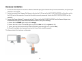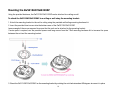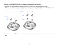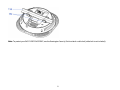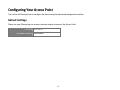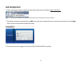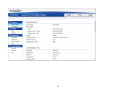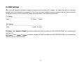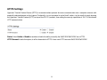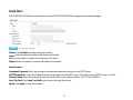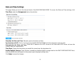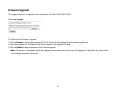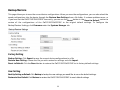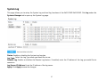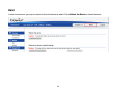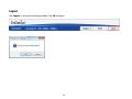
1
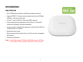
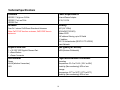
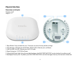
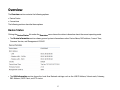
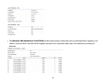
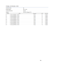
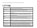
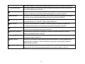
1
Table of Contents
Chapter 1 Product Overview ....................................................................................................................................................... 5
Key Features.............................................................................................................................................................................................................................. 6
Introduction................................................................................................................................................................................................................................ 7
System Requirements ........................................................................................................................................................................................................... 8
Package Contents.................................................................................................................................................................................................................... 8
Applications................................................................................................................................................................................................................................ 9
Technical Specifications .................................................................................................................................................................................................... 10
Physical Interface ................................................................................................................................................................................................................. 11
Chapter 2 Before You Begin......................................................................................................................................................12
Considerations for Wireless Installation..................................................................................................................................................................... 13
Computer Settings ............................................................................................................................................................................................................... 14
Hardware Installation ......................................................................................................................................................................................................... 18
Mounting the EWS310AP/EWS320AP ........................................................................................................................................................................ 19
Chapter 3 Configuring Your Access Point................................................................................................................................22
Default Settings .................................................................................................................................................................................................................... 23
Web Configuration................................................................................................................................................................................................................ 24
Chapter 4 Overview ....................................................................................................................................................................26
Device Status.......................................................................................................................................................................................................................... 27
Connections............................................................................................................................................................................................................................. 30
Chapter 5 Network .....................................................................................................................................................................31
IPv4 Settings .......................................................................................................................................................................................................................... 32
IPv6 Settings .......................................................................................................................................................................................................................... 33
Spanning Tree Settings ..................................................................................................................................................................................................... 34
Chapter 6 2.4GHz & 5GHz Wireless ..........................................................................................................................................35
Wireless Settings .................................................................................................................................................................................................................. 36
2.4GHz/5GHz SSID Profile................................................................................................................................................................................................. 38
Wireless Security................................................................................................................................................................................................................... 40
Wireless MAC Filter .............................................................................................................................................................................................................. 43
Traffic Shaping....................................................................................................................................................................................................................... 44
Guest Network ....................................................................................................................................................................................................................... 45
Fast Handover........................................................................................................................................................................................................................ 47
Management VLAN Settings ........................................................................................................................................................................................... 48
Chapter 7 Management..............................................................................................................................................................49
SNMP Settings ....................................................................................................................................................................................................................... 50
CLI/SSH Settings ................................................................................................................................................................................................................... 52
HTTPS Settings ..................................................................................................................................................................................................................... 53
Email Alert................................................................................................................................................................................................................................ 54
Date and Time Settings ..................................................................................................................................................................................................... 55
WiFi Scheduler........................................................................................................................................................................................................................ 56
Tools ........................................................................................................................................................................................................................................... 58
LED Control .............................................................................................................................................................................................................................. 61
Device Discovery................................................................................................................................................................................................................... 62
Chapter 8 System Manager .......................................................................................................................................................63
Account Setting..................................................................................................................................................................................................................... 64
Firmware Upgrade ................................................................................................................................................................................................................ 65
Backup/Restore ..................................................................................................................................................................................................................... 66
System Log.............................................................................................................................................................................................................................. 67
Reset .......................................................................................................................................................................................................................................... 68
Logout........................................................................................................................................................................................................................................ 69
Appendix ......................................................................................................................................................................................70
Appendix A - FCC Interference Statement ................................................................................................................................................................ 71
Appendix B - IC Interference Statement .................................................................................................................................................................... 72
3
Appendix C - CE Interference Statement ................................................................................................................................................................... 74
4
Chapter 1
Product Overview
5
Introduction
Key Features
Up to 28 dBm transmit power, enabling long range connectivity
Supports IEEE802.11a/b/g/n wireless standards with up to 450 Mbps /
300Mbps*1 data rate on each band
Six/Four*2 internal 5dBi Omni-Directional MIMO antennas
Can be monitored after deployment with EnGenius EZ Controller™
software for Windows (Free online download)
Can be used with included power adapter or via PoE with PoE 802.3at capable Switches or Injectors
Dual Band/Three Stream
Band Steering shifts dual band clients to 5 GHz for better throughput
performance
Secured Guest Network
Note: 1. EWS310AP supports 300Mbps; EWS320AP supports 450Mbps.
2. EWS310AP has four antennas; EWS320AP has six antennas.
6
Introduction
The EWS310AP/EWS320AP is a high-powered, long-range, Dual-band concurrent Wireless 802.11a/b/g/n Access Point. It is designed to
operate in numerous environments; from large homes, small and medium-sized businesses, multiple-floor offices, hotels, and other
venues, to larger enterprise deployments. Its high-powered, long-range characteristics make it a cost-effective alternative to ordinary
Access Points that don’t have the range and reach to connect to a growing number of wireless users who wish to connect to a large
home or business network.
The EWS310AP/EWS320AP supports the 2.4 GHz frequency band under the 802.11b/g/n mode while at the same time providing a 5
GHz band for communicating or transferring files in a less congested network frequency band.
The EWS310AP/EWS320AP also delivers up to 6x faster wireless speeds compared to legacy 802.11a/b/g wireless devices. Even
though the EWS310AP/EWS320AP has been designed and engineered for heavy traffic and demanding business environments, in
larger housing environments as it can efficiently extend the wireless range of an existing home router. This makes it especially ideal
in architecturally-challenging structures, providing whole home connectivity.
To protect sensitive data during wireless transmissions, the EWS310AP/EWS320AP offers different encryption settings for wireless
transmissions, including industry standard WPA and WPA2 encryption. The EWS310AP/EWS320AP also includes MAC address
filtering to allow network administrators to offer network access only to known computers and other devices based on their MAC
addresses.
Maximum data rates are based on IEEE 802.11 standards. Actual throughput and range may vary depending on many factors including environmental conditions, distance
between devices, radio interference in the operating environment, and mix of devices in the network. Features and specifications subject to change without notice.
Trademarks and registered trademarks are the property of their respective owners. For United States of America: Copyright © 2013 EnGenius Technologies, Inc. All rights
reserved.
7
System Requirements
The following are the Minimum System Requirements in order configure the device:
Computer with an Ethernet interface or wireless network capability
Windows OS (XP, Vista, 7, 8), Mac OS, or Linux-based operating systems
Web-Browsing Application (i.e. : Internet Explorer, Firefox, Chrome, Safari, or another similar browser application)
Package Contents
The EWS310AP/EWS320AP package contains the following items (all items must be in package to issue a refund):
EWS310AP or EWS320AP Access Point
Power Adapter
RJ-45 Ethernet Cable
Quick Installation Guide
Ceiling and Wall Mount Screw kit
8
Applications
Wireless LAN (WLAN) products are easy to install and highly efficient. The following list describes some of the many applications
made possible through the power and flexibility of WLANs:
Difficult-to-Wire Environments: There are many situations where wires cannot be installed, deployed easily, or cannot be
hidden from view. Older buildings, sites with multiple buildings, and/or areas that make the installation of a Ethernet-based
LAN impossible, impractical or expensive are sites where WLAN can be a network solution.
Temporary Workgroups: Create temporary workgroups/networks in more open areas within a building; auditoriums,
amphitheaters classrooms, ballrooms, arenas, exhibition centers, or temporary offices where one wants either a permanent or
temporary Wireless LAN established.
The Ability to Access Real-Time Information: Doctors/Nurses, Point-of-Sale Employees, and/or Warehouse Workers can access
real-time information while dealing with patients, serving customers, and/or processing information.
Frequently Changing Environments: Set up networks in environments that change frequently (i.e.: Show Rooms, Exhibits, etc.).
Small Office and Home Office (SOHO) Networks: SOHO users require a cost-effective, easy, and quick installation of a small
network.
Training/Educational Facilities: Training sites at corporations or students at universities use wireless connectivity to exchange
information between peers and easily access information for learning purposes.
9
Technical Specifications
Standard
Power Requirements
IEEE802.11b/g/n on 2.4GHz
IEEE802.11a/n on 5GHz
IEEE802.3at
External Power Adapter
DC IN, 12V/2A
Antenna
Security
*
Four/Six Internal 5 dBi Ommi-Directional Antennas
Note: EWS310AP has four antennas; EWS320AP has six
antennas.
WEP (64/128bit)
WPA/WPA2(TKIP/AES)
Hidden ESSID
MAC address filtering, up to 50 fields
L2 Isolation
802.1X Authenticatior (MD5/TLS/TTLS/PEAP)
Guest Network
Physical Interface
QoS (Quality of Service)
1 x 10/100/1000 Gigabit Ethernet Port
1 x Reset Button
1 x Power Connector
WMM (Wireless Multimedia)
LED Indicator
Physical/Environment Conditions
Power
WLAN (Wireless Connection)
LAN
Operating:
Temperature: 32 oF to 104 oF (-20oC to 40oC)
Humidity (Non-condensing): 90% or less
Storage:
Temperature: 32oF to 140oF (-20oC to 60oC)
Humidity (Non-condensing): 90% or less
10
Physical Interface
Dimensions and Weights
Diameter: 6.36”
Height: 2.17”
1. Reset Button: Press and hold for over 10 seconds to reset to factory default settings.
2. LED Indicators: LED lights for WLAN 5GHz, WLAN 2.4GHz, Ethernet port, and Power
3. LAN Port (802.3at PoE): Ethernet port for RJ-45 cable.
4. Power Connector: 12V DC IN for Power.
5. Ceiling (Wall) Mount Hole: Using the provided hardware, the EWS310AP/EWS320AP can be attached to a ceiling or wall.
6. Kensington Security Slot: To protect your EWS310AP/EWS320AP, use the Kensington Security Slot to attach a cable lock.
11
Chapter 2
Before You Begin
12
Before You Begin
This section will guide you through the installation process. Placement of the EnGenius EWS310AP/EWS320AP essential to
maximize the Access Point’s performance. Avoid placing the EWS310AP/EWS320AP in an enclosed space such as a closet, cabinet,
or stairwell.
Considerations for Wireless Installation
The operating distance of all wireless devices can often not be pre-determined due to a number of unknown obstacles in
the environment in which the device is deployed. Obstacles such as the number, thickness, and location of walls, ceilings,
or other objects that the EWS310AP/EWS320AP’s wireless signals must pass through can weaken the signal. Here are some
key guidelines for allowing the EWS310AP/EWS320AP to have an optimal wireless range during setup.
Keep the number of walls and/or ceilings between the EWS310AP/EWS320AP and other network devices to a minimum. Each
wall and/or ceiling can reduce the signal strength, resulting in a lower overall signal strength.
Building materials make a difference. A solid metal door and/or aluminum stubs may have a significant negative effect on the
signal strength of the EWS310AP/EWS320AP. Locate your wireless devices carefully so the signal can pass through drywall
and/or open doorways. Materials such as glass, steel, metal, concrete, water (example: fish tanks), mirrors, file cabinets, and/or
brick can also diminish wireless signal strength.
Interference from your other electrical devices and/or appliances that generate RF noise can also diminish the
EWS310AP/EWS320AP’s signal strength. The most common types of devices are microwaves or cordless phones.
13
Computer Settings
Windows XP/Windows 7
In order to use the EWS310AP/EWS320AP, you must first configure the TCP/IPv4 connection of your Windows OS computer system.
1. Click the Start button and open the Control Panel.
Windows XP
Windows 7
2a. In Windows XP, click on Network Connections.
2b. In Windows 7, click View network status and tasks in the Network and Internet section, then select Change adapter
14
settings.
3. Right click on Local Area Connection and select Properties.
4. Select Internet Protocol Version 4 (TCP/IPv4) and then select Properties.
15
5. Select Use the following IP address and enter an IP address that is different from the
EWS310AP/EWS320AP and Subnet mask, then click OK.
Note: Ensure that the IP address and Subnet mask are on the same subnet as the
device.
For example: EWS310AP/EWS320AP IP address: 192.168.1.1
PC IP address: 192.168.1.2 – 192.168.1.255
PC Subnet mask: 255.255.255.0
16
Apple Mac OS X
1. Go to System Preferences (it can be opened in the Applications folder or by electing it in the Apple Menu).
2. Select Network in the Internet & Network section.
3. Highlight Ethernet.
4. In Configure IPv4, select Manually.
5. Enter an IP address that is different from the EWS310AP/EWS320AP
and Subnet mask, then click OK.
Note: Ensure that the IP address and Subnet mask are on the same
subnet as the device.
For example: EWS310AP/EWS320AP IP address: 192.168.1.1
PC IP address: 192.168.1.2 – 192.168.1.255
PC Subnet mask: 255.255.255.0
6. Click Apply when finished.
17
Hardware Installation
1. Ensure that the computer in use has an Ethernet Controller port (RJ-45 Ethernet Port). For more information, verify with your
computer’s user manual.
2. Connect one end of the Category 5e Ethernet cable into the RJ-45 port of the EWS310AP/EWS320AP and the other end to
the RJ-45 port of the computer. Ensure that the cable is securely connected to both the EWS310AP/EWS320AP and the
computer.
3. Connect the Power Adapter DC connector to the DC-IN port of the EWS310AP/EWS320AP and the Power Adapter to an
available electrical outlet. Once both connections are secure, verify the following:
a) Ensure that the POWER light is on (it will be orange).
b) Ensure that the 2.4 GHz/5 GHz WLAN light is on (it will be blue for 2.4G, and green for 5G).
c) Ensure that the LAN (Computer/EWS310AP/EWS320AP Connection) light is on (it will be blue).
d) Once all three lights are on, proceed to set up the Access Point using the computer.
This diagram depicts the hardware configuration.
18
Mounting the EWS310AP/EWS320AP
Using the provided hardware, the EWS310AP/EWS320AP can be attached to a ceiling or wall.
To attach the EWS310AP/EWS320AP to a ceiling or wall using the mounting bracket:
1. Attach the mounting bracket to the wall or ceiling using the provided wall/ceiling mounting hardware kit.
2. Insert the provided short screws into the bottom cover of the EWS310AP/EWS320AP.
Leave enough of the screws exposed to ensure that the unit can be attached to the mounting bracket.
If extra space is required, use the provided spacers and long screws from the T-Rail mounting hardware kit to increase the space
between the unit and the mounting bracket.
3. Mount the EWS310AP/EWS320AP on the mounting bracket by rotating the unit clockwise about 90 degrees to secure it in place.
19
Attaching the EWS310AP/EWS320AP to a ceiling using the provided T-Rail connectors:
1. Attach the T-Rail connectors to the bottom cover of the EWS310AP/EWS320AP using the provided short screws.
Note: Two sizes of T-Rail connectors are included in the mounting hardware kit: 15/16in (2.38cm) and 9/16in (1.43cm). If extra
space is required to accommodate drop ceiling tiles, use the provided spacers and long screws.
2. Line up the connected T-Rail connectors with an appropriately sized rail and press the unit onto the rail until it snaps into
place.
20
Note: To protect your EWS310AP/EWS320AP, use the Kensington Security Slot to attach a cable lock (cable lock is not included).
21
Chapter 3
Configuring Your Access Point
22
Configuring Your Access Point
This section will show you how to configure the device using the web-based configuration interface.
Default Settings
Please use your Ethernet port or wireless network adapter to connect the Access Point.
IP Address 192.168.1.1
Username/Password admin/admin
23
Web Configuration
1. Open a web browser (Internet Explorer/Firefox/Safari) and enter the IP Address http://192.168.1.1.
Note: If you have changed the default LAN IP Address of the Access Point, ensure you enter the correct IP Address.
2. The default username and password are: admin. Once you have entered the correct username and password, click the Login
button to open the web-based configuration page.
3. If successful, you will be logged in and see the EWS310AP/EWS320AP User Menu.
24
25
Chapter 4
Overview
26
Overview
The Overview section contains the following options:
• Device Status
• Connections
The following sections describe these options.
Device Status
Clicking the Device Status link under the Overview menu shows the status information about the current operating mode.
The Device Information section shows general system information such as Device Name, MAC address, Current Time,
Firmware Version, and Management VLAN ID
The LAN Information section shows the Local Area Network settings such as the LAN IP Address, Subnet mask, Gateway,
DNS Address, DHCP Client, and STP status.
27
The Wirelesss LAN Information 2.4 GHz/5GHz section shows wireless information such as Operating Mode, Frequency, and
Channel. Since the EWS310AP/EWS320AP supports multiple-SSIDs, information about each SSID and security settings are
displayed.
28
29
Connections
Clicking the Connections link under the Device Status menu displays the list of clients associated to the
EWS310AP/EWS320AP’s 2.4GHz/5GHz, along with the MAC address, TX, RX and signal strength for each client. Clicking Kick in
the Block column removes this client.
Click Refresh to refresh the Connection List page.
30
Chapter 5
Network
31
Basic
This page allows you to modify the device’s IP settings and the Spanning Tree settings. Enabling Spanning Tree protocol will
prevent network loops in your LAN network.
IPv4 Settings
IP Network Setting: Select whether the device IP address will use the static IP address specified in the IP Address field or be
obtained automatically when the device connects to a DHCP server.
IP Address: The IP Address of this device.
IP Subnet Mask: The IP Subnet mask of this device.
Gateway: The Default Gateway of this device. Leave it blank if you are unsure of this setting.
Primary/Secondary DNS: The primary/secondary DNS address for this device.
32
IPv6 Settings
Link-Local Address: Check this if you want to use Link-Local Address.
IP Address: The IPv6 IP Address of this device.
Subnet Prefix Length: The IPv6 Subnet Prefix Length of this device.
Gateway: The IPv6 Default Gateway of this device. Leave it blank if you are unsure of this setting.
Primary / Secondary DNS: The primary / secondary DNS address for this device.
33
Spanning Tree Settings
Status: Enables or disables the Spanning Tree function.
Hello Time: Specify Bridge Hello Time, in seconds. This value determines how often the device sends handshake packets to
communicate information about the topology throughout the entire Bridged Local Area Network.
Max Age: Specify Bridge Max Age, in seconds. If another bridge in the spanning tree does not send a hello packet for a long period
of time, it is assumed to be inactive.
Forward Delay: Specifies Bridge Forward Delay, in seconds. Forwarding Delay Time is the time spent in each of the Listening and
Learning states before the Forwarding state is entered. This delay is provided so that when a new bridge comes onto a busy
network, it analyzes data traffic before participating.
Priority: Specify the Priority Number. A smaller number has greater priority.
Save: Click Save to confirm the changes.
34
Chapter 6
2.4GHz & 5GHz Wireless
35
Wireless Network
This page displays the current status of the Wireless settings of the EWS310AP/EWS320AP.
Wireless Settings
Device Name: Enter a name for the device. The name you type appears in SNMP management. This name is not the SSID and is not
broadcast to other devices.
Band Steering: Enable Band Steering to sends 802.11n clients to the 5GHz band, where 802.11b/g clients cannot go, and
leaves the 802.11b/g clients in 2.4GHz to operate at their slower rates. Band Steering works within the Access Point by
directing 5GHz-capable clients to that band.
*Note: In order for the Band Steering function to work properly, both the 2.4GHz and the 5GHz SSID and security settings
must be under the same selection settings.
36
Wireless Mode: Supports 802.11b/g/n mixed mode in 2.4GHz and 802.11a/n mixed mode in 5GHz.
Channel HT Mode: The default channel bandwidth is 20/40MHz. The larger the channel bandwidth, the better the transmission
quality and speed. This option is only available for 802.11n modes only.
Extension Channel: Use the drop-down menu to set the Extension Channel as Upper or Lower channel. An extension channel is a
secondary channel used to bond with the primary channel to increase this range to 40MHz allowing for greater bandwidth. This
option is only available when Wireless Mode is 802.11n and Channel HT Mode is 20/40 MHz or 40MHz.
Channel: Select the channel appropriate for your WLAN deployment.
Transmit Power: Select the transmit power for the radio. Increasing the power improves performance, but if two or more access
points are operating in the same area on the same channel, it may cause interference.
Data Rate: Use the drop-down list to set the available transmit data rates permitted for wireless clients. The data rate affects the
throughput of the access point. The lower the data rate, the lower the throughput, but the longer transmission distance.
RTS/CTS Threshold: Specifies the threshold package size for RTC/CTS. A small number causes RTS/CTS packets to be sent more
often and consumes more bandwidth.
Client Limits: Limits the total number of clients.
Aggregation: Merges data packets into one packet. This option reduces the number of packets, but also increases packet sizes.
AP Detection: AP Detection can select the best channel to use by scanning nearby areas for Access Points.
37
2.4GHz/5GHz SSID Profile
Under Wireless Settings, you can edit the SSID profile to fit your needs. Click Edit under the SSID you would like to make changes
to.
38
Enable: Check this option to enable this profile.
SSID: Specifies the SSID for the current profile.
Security: Displays the Security Mode the SSID uses. You can click Edit to change the security mode. For more details, see the next
section.
Hidden SSID: Check this option to hide the SSID from clients. If checked, the SSID will not appear in the site survey.
Client Isolation: Check this option to prevent communication between client devices.
VLAN Isolation: Check this option to enable VLAN Isolation feature.
VLAN ID: Specifies the VLAN ID for the SSID profile.
39
Wireless Security
The Wireless Security section lets you configure the EWS310AP/EWS320AP’s security modes: WEP, WPA-PSK, WPA2-PSK, WPA-PSK
Mixed, WPA-Enterprise, WPA2-Enterprise and WPA Mixed Enterprise.
It is strongly recommended that you use WPA2-PSK. Click on the Edit button under Wireless Settings next to the SSID to change
the security settings.
WEP
Auth Type: Select Open System or Shared Key.
Input Type: ASCII: Regular Text (Recommended) or HEX: Hexadecimal Numbers (For advanced users).
Key Length: Select the desired option and ensure the wireless clients use the same setting. Your choices are: 64, 128, and 152-bit
password lengths.
Default Key: Select the key you wish to be default. Transmitted data is ALWAYS encrypted using the Default Key; the other Keys
are for decryption only. You must enter a Key Value for the Default Key.
Encryption Key: Enter the Key Value or values you wish to use. The default is none.
40
WPA-PSK/WPA2-PSK (Pre-Shared Key)
Encryption: Select the WPA/WPA2 encryption type you would like to use. Available options are Both, TKIP(Temporal Key Integrity
Protocol) and AES(Advanced Encryption Standard). Please ensure that your wireless clients use the same settings.
Passphrase: Wireless clients must use the same Key to associate the device. If using ASCII format, the Key must be from 8 to 63
characters in length. If using HEX format, the Key must be 64 HEX characters in length.
Group Key Update Interval: Specify how often, in seconds, the Group Key changes.
WPA/WPA2-Enterprise
Encryption: Select the WPA/WPA2 encryption type you would like to use. Available options are Both, TKIP(Temporal Key Integrity
41
Protocol) and AES(Advanced Encryption Standard). Please ensure that your wireless clients use the same settings.
Group Key Update Interval: Specify how often, in seconds, the group key changes.
Radius Server: Enter the IP address of the Radius server.
Radius Port: Enter the port number used for connections to the Radius server.
Radius Secret: Enter the secret required to connect to the Radius server.
Radius Accounting: Enables or disables the accounting feature.
Radius Accounting Server: Enter the IP address of the Radius accounting server.
Radius Accounting Port: Enter the port number used for connections to the Radius accounting server.
Radius Accounting Secret: Enter the secret required to connect to the Radius accounting server.
Interim Accounting Interval: Specify how often, in seconds, the accounting data sends.
Note: 802.11n does not allow WEP/WPA-PSK TKIP/WPA2-PSK TKIP security mode. The connection mode will automatically change
from 802.11n to 802.11g.
42
Wireless MAC Filter
Wireless MAC Filter is used to allow or deny network access to wireless clients (computers, tablet PCs, NAS, smartphones, etc.)
according to their MAC addresses. You can manually add a MAC address to restrict permission to access EWS310AP/EWS320AP. The
default setting is: Disable Wireless MAC Filter.
ACL (Access Control List) Mode: Determines whether network access is granted or denied to clients whose MAC addresses appear
in the MAC address table on this page. Choices given are: Disabled, Deny MAC in the list, or Allow MAC in the list.
MAC Address: Enter the MAC address of the wireless client.
Add: Click Add to add the MAC address to the MAC Address table.
Delete: Deletes the selected entries.
43
Traffic Shaping
Traffic Shaping regulates the flow of packets leaving an interface to deliver improved Quality of Service.
Enable Traffic Shaping: Select to Enable or Disable Wireless Traffic Shaping.
Download Limit: Specifies the wireless transmission speed used for downloading.
Upload Limit: Specifies the wireless transmission speed used for uploading.
Save: Click Save to apply the changes.
44
Guest Network
The Guest Network function allows administrators to grant Internet connectivity to visitors or guests while keeping other
networked devices (computers and hard drives) and sensitive personal or company information private and secure.
Enable SSID: Select to Enable or Disable SSID broadcasting.
SSID: Specify the SSID for the current profile. This is the name visible on the network to wireless clients.
Security: You can use None or WPA-PSK / WPA2-PSK security for this guest network.
Hidden SSID: Check this option to hide the SSID from broadcasting to discourage wireless users from connecting to a particular
SSID.
Client Isolation: Check this option to prevent wireless clients associated with your access point to communicate with other
wireless devices connected to the AP.
45
After enabling Guest Network in the SSID Config page, assign an IP Address, Subnet Mask and DHCP server IP address range for
this Guest Network.
Manual IP Settings
IP Address: Specify an IP Address for the Guest Network
Subnet Mask: Specify the the Subnet Mask IP Address for the Guest Network
Automatic DHCP Server Settings
Starting IP Address: Specify the starting IP Address range for the Guest Network.
Ending IP Address: Specify the ending IP Address range for the Guest Network.
WINS Server IP: Specify the WINS Server IP Address for the Guest Network. WINS means Windows Internet Name Service. It is
Microsoft's implementation of NetBIOS Name Service (NBNS), a name server and service for NetBIOS computer names.
46
Fast Handover
With Fast Handover enabled, the AP will send a disassociation request to the wireless client and let it find another AP to
handover and associate upon detecting the wireless client’s RSSI value lower than specified. The RSSI value can be adjusted to
allow more clients to stay associated to this AP. Note that setting the RSSI value too low may cause wireless clients to
reconnect frequently.
47
Management VLAN Settings
This section allows you to assign a VLAN tag to the packets. A VLAN is a group of computers on a network whose software has
been configured so that they behave as if they were on a separate Local Area Network (LAN). Computers on VLAN do not have
to be physically located next to one another on the LAN.
Status: If your network includes VLANs and if tagged packets need to pass through the Access Point, select Enable and enter
the VLAN ID. Otherwise, click Disable.
Save: Click Save to apply the changes.
Note: If you reconfigure the Management VLAN ID, you may lose your connection to the EWS310AP/EWS320AP. Verify that the
DHCP server supports the reconfigured VLAN ID and then reconnect to the EWS310AP/EWS320AP using the new IP address.
48
Chapter 7
Management
49
SNMP Settings
This page allows you to assign the Contact Details, Location, Community Name, and Trap Settings for Simple Network Management
Protocol (SNMP). This is a networking management protocol used to monitor network attached devices. SNMP allows messages (called
protocol data units) to be sent to various parts of the network. Upon receiving these messages, SNMP compatible devices (called agents)
returns the data stored in their Management Information Bases. To configure SNMP Settings, click under the Advanced tab on the side
bar under Management.
Status: Enables or Disables the SNMP feature.
Contact: Specifies the contact details of the device.
50
Location: Specifies the location of the device.
Port: Displays the port number.
Community Name (Read Only): Specifies the password for the SNMP community for read only access.
Community Name (Read/Write): Specifies the password for the SNMP community with read/write access.
Trap Destination Address: Specifies the port and IP address of the computer that will receive the SNMP traps.
Trap Destination Community Name: Specifies the password for the SNMP trap community.
SNMPv3 Status: Enables or Disables the SNMPv3 feature.
User Name: Specifies the username for the SNMPv3.feature
Auth Protocol: Select the Authentication Protocol type: MDS or SHA.
Auth Key: Specify the Authentication Key for authentication.
Priv Protocol: Select the Privacy Protocol type: DES.
Priv Key: Specifies the privacy key for privacy.
Engine ID: Specifies the Engine ID for SNMPv3.
51
CLI/SSH Settings
Most users will configure the device through the graphical user interface (GUI). However, for those who prefer an alternative
method there is the command line interface (CLI). The CLI can be access through a command console, modem or Telnet connection.
For security’s concern, you can enable SSH (Secure Shell) to establish a secure data communication.
CLI Status: Select Enable or Disable to enable or disable the ability to modify the EWS310AP/EWS320AP via a command line
interface (CLI).
SSH Status: Select Enable or Disable to enable or disable the ability to modify the EWS310AP/EWS320AP via a command line
interface (CLI) with a secure channel.
52
HTTPS Settings
Hypertext Transfer Protocol Secure (HTTPS) is a communications protocol for secure communication over a computer network, with
especially wide deployment on the Internet. Technically, it is not a protocol in and of itself; rather, it is the result of simply layering
the Hypertext Transfer Protocol (HTTP) on top of the SSL/TLS protocol, thus adding the security capabilities of SSL/TLS to standard
HTTP communications.
Status: Select Enable or Disable to enable or disable the ability to modify the EWS310AP/EWS320AP via a HTTPS.
HTTPS forward: Enable this option; it will be forwarded to HTTPS if user uses HTTP to access EWS310AP/EWS320AP.
53
Email Alert
EWS310AP/EWS320AP will send email alerts when EWS310AP/EWS320AP’s configuration has been changed.
Status: Check Enable to enable Email Alert feature.
From: Enter the address to show as the sender of the email.
To: Enter the address to show as the receiver of the email.
Subject: Enter the subject to show as the subject of the email.
Email Account
Username/Password: Enter the username and password required to connect to the SMTP server.
SMTP Server/Port: Enter the IP address/domain name and port of the SMTP server. The default port of SMTP Server is port 25.
Security Mode: Select the mode of security for the Email alert. The options are None, SSL/TLS and STARTTLS.
Send Test Mail: Click Send Test Mail button to test the Email Alert setup.
Apply: Click Apply to save the changes.
54
Date and Time Settings
This page allows you to set the internal clock of the EWS310AP/EWS320AP. To access the Date and Time settings, click
Time Zone under the Management tab on the side bar.
Manually Set Date and Time: Manually specify the date and time.
Synchronize with PC: Click to Synchronize the EWS310AP/EWS320AP with the computer’s internal clock.
Automatically Get Date and Time: Enter the IP address of an NTP server or use the default NTP server to have the
internal clock set automatically.
Time Zone: Choose the time zone you would like to use from the drop-down list.
Enable Daylight Savings: Check the box to enable or disable daylight savings time for the EWS310AP/EWS320AP. Next,
enter the dates that correspond to the present year’s daylight savings time.
Click Apply to save the changes.
55
WiFi Scheduler
Use the schedule function to reboot EWS310AP/EWS320AP or control the wireless availability on a routine basis. The
Schedule function relies on the GMT time setting acquired from a network time protocol (NTP) server. For details on how
to connect the EWS310AP/EWS320AP to an NTP server, see Date and Time Settings.
Auto Reboot Settings
You can specify how often you would like to reboot the EWS310AP/EWS320AP.
Status: Enables or disables the Auto Reboot function.
Timer: Specifies the time and frequency in rebooting the EWS310AP/EWS320AP by Min, Hour and Day.
56
WiFi Scheduler
Status: Enables or disables the WiFi Scheduler function.
Wireless Radio: Select 2.4GHz or 5GHz to use WiFi Schedule.
SSID Selection: Select a SSID to use WiFi Schedule.
Schedule Templates: EWS310AP/EWS320AP provides three templates: Always available, Available 8-5 daily and Available 8-5
daily except weekends. Select Custom schedule if you want to set the schedule manually.
Schedule Table: Set the schedule manually.
57
Tools
This section allows you to analyze the connection quality of the EWS310AP/EWS320AP and trace the routing table to a
target in the network.
Ping Test Parameters
Target IP/Domain Name: Enter the IP address or Domain name you would like to search.
Ping Packet Size: Enter the packet size of each ping.
Number of Pings: Enter the number of times you wish to ping.
Start: Click Start to begin pinging target device (via IP).
58
Traceroute Parameters
Target IP/Domain Name: Enter an IP address or domain name you wish to trace.
Start: Click Start to begin the trace route operation.
Stop: Halts the traceroute test.
59
Speed Test Parameters
Target IP/Domain Name: Enter an IP address or domain name you wish to run a Speed Test for.
Time Period: Enter the time in seconds that you would like the test to run for and in how many intervals.
Start: Starts the Speed Test.
IPv4 / IPv6 Port: EWS310AP/EWS320AP uses IPv4 port 5001 and IPv6 port 5002 for the speed test.
60
LED Control
This section allows you to control the LED control functions: Power status, LAN interface and 2.4GHz/5GHz WLAN interface.
Click Apply to save the settings after selecting your choices from the boxes.
61
Device Discovery
Under Device Discovery, you can choose for the EWS310AP/EWS320AP to automatically scan for local devices to connect to. Click
Scan to begin the process.
62
Chapter 8
System Manager
63
Account Setting
This page allows you to change the EWS310AP/EWS320AP username and password. By default, the username is admin and the
password is admin. The password can contain from 0 to 12 alphanumeric characters and is case sensitive.
Administrator Username: Enter a new username for logging in to the Administrator Username entry box.
Current Password: Enter the old password for logging in to the Current Password entry box.
New Password: Enter the new password for logging in to the New Password entry box.
Verify Password: Re-enter the new password in the Verify Password entry box for confirmation.
Apply: Click Apply to save the changes.
Note: it is highly recommended that you change you password to something more unique for greater security.
64
Firmware Upgrade
This page allows you to upgrade the Firmware of the EWS310AP/EWS320AP.
To Perform the Firmware Upgrade:
1. Click the Browse… button and navigate the OS File System to the location of the Firmware upgrade file.
2. Select the upgrade file. The name of the file will appear in the Upgrade File field.
3. Click the Upload button to commence the Firmware upgrade.
Note: The device is unavailable during the upgrade process and must restart when the upgrade is completed. Any connections
to or through the device will be lost.
65
Backup/Restore
This page allows you to save the current device configurations. When you save the configurations, you can also reload the
saved configurations into the device through the Restore New Settings from a file folder. If extreme problems occur, or
if you have set the EWS310AP/EWS320AP incorrectly, you can use the Reset button in the Reset to Default section to
restore all the configurations of the EWS310AP/EWS320AP to the original default settings. To Configure the
Backup/Restore Settings, click Firmware under the Systems Manager tab.
Factory Setting
Backup Setting: Click Export to save the current device configurations to a file.
Restore New Setting: Choose the file you wish restore for settings and click Import.
Reset to Default: Click the Reset button to restore the EWS310AP/EWS320AP to its factory default settings.
User Setting
Back Up Setting as Default: Click Backup to backup the user settings you would like to use as the default settings.
Restore to User Default: Click Restore to restore the EWS310AP/EWS320AP to user’s default settings.
66
System Log
This page allows you to setup the System Log and local log functions of the EWS310AP/EWS320AP. Click Log under the
Systems Manager tab to open up the System Log page.
Status: Enables or disables the System Log function.
Log Type: Select the Log Type mode you would like to use.
Remote Log: Enables or disables the Remote Log feature. If enabled, enter the IP address of the Log you would like to
remote to.
Log Server IP Address: Enter the IP address of the log server.
Apply: Click Apply to save the changes.
67
Reset
In some circumstances, you may be required to force the device to reboot. Click on Reboot the Device to reboot the device.
68
Logout
Click Logout, it will pop up a warning window. Click OK to logout.
69
Appendix
70
Appendix A - FCC Interference Statement
Federal Communication Commission Interference Statement
This equipment has been tested and found to comply with the limits for a Class B digital device, pursuant to Part 15 of the FCC Rules.
These limits are designed to provide reasonable protection against harmful interference in a residential installation. This equipment
generates, uses, and can radiate radio frequency energy and, if not installed and used in accordance with the instructions, may cause
harmful interference to radio communications. However, there is no guarantee that interference will not occur in a particular installation.
If this equipment does cause harmful interference to radio or television reception, which can be determined by turning the equipment off
and on, the user is encouraged to try to correct the interference by one of the following measures:
• Reorient or relocate the receiving antenna.
• Increase the separation between the equipment and receiver.
• Connect the equipment into an outlet on a circuit different from that to which the receiver is connected.
• Consult the dealer or an experienced radio/TV technician for help.
FCC Caution:
Any changes or modifications not expressly approved by the party responsible for compliance could void the user’s
authority to operate this equipment.
This device complies with Part 15 of the FCC Rules. Operation is subject to the following two conditions: (1) This device may not cause
harmful interference, and (2) this device must accept any interference received, including interference that may cause undesired operation.
This transmitter must not be co-located or operating in conjunction with any other antenna or transmitter. Operations in the 5.15-5.25 GHz band
are restricted to indoor usage only.
IMPORTANT NOTE:
Radiation Exposure Statement
This equipment complies with FCC radiation exposure limits set forth for an uncontrolled environment. This equipment should be installed
and operated with a minimum distance of 33 cm between the radiator & your body.
71
Appendix B - IC Interference Statement
Industry Canada Statement
This device complies with RSS-210 of the Industry Canada Rules. Operation is subject to the following two conditions: (1) This
device may not cause harmful interference, and (2) this device must accept any interference received, including interference
that may cause undesired operation.
Ce dispositif est conforme à la norme CNR-210 d’Industrie Canada applicable aux appareils radio exempts de licence. Son
fonctionnement est sujet aux deux conditions suivantes: (1) le dispositif ne doit pas produire de brouillage préjudiciable, et (2)
ce dispositif doit accepter tout brouillage reçu, y compris un brouillage susceptible de provoquer un fonctionnement
indésirable.
Caution:
(i) the device for operation in the band 5150-5250 MHz is only for indoor use to reduce the potential for harmful interference
to co-channel mobile satellite systems;
(ii) high-power radars are allocated as primary users (i.e. priority users) of the bands 5250-5350 MHz and 5650-5850 MHz and
that these radars could cause interference and/or damage to LE-LAN devices.
Avertissement:
(i) les dispositifs fonctionnant dans la bande 5150-5250 MHz sont réservés uniquement pour une utilisation à l’intérieur afin
de réduire les risques de brouillage préjudiciable aux systèmes de satellites mobiles utilisant les mêmes canaux;
(ii) De plus, les utilisateurs devraient aussi être avisés que les utilisateurs de radars de haute puissance sont désignés
utilisateurs principaux (c.-à-d., qu’ils ont la priorité) pour les bandes 5250-5350 MHz et 5650-5850 MHz et que ces radars
pourraient causer du brouillage et/ou des dommages aux dispositifs LAN-EL.
72
FOR MOBILE DEVICE USAGE
Radiation Exposure Statement
This equipment complies with IC radiation exposure limits set forth for an uncontrolled environment. This equipment should be installed and
operated with a minimum distance of 33 cm between the radiator & your body.
Pour l’utilisation de dispositifs mobiles)
Déclaration d’exposition aux radiations:
Cet équipement est conforme aux limites d’exposition aux rayonnements IC établies pour un environnement non contrôlé. Cet
équipement doit être installé et utilisé avec un minimum de 33 cm de distance entre la source de rayonnement et votre corps.
73
Appendix C - CE Interference Statement
Europe – EU Declaration of Conformity
•
EN60950-1
Safety of Information Technology Equipment
•
EN50385
Generic standard to demonstrate the compliance of electronic and electrical apparatus with the basic restrictions related to human exposure
to electromagnetic fields (0 Hz - 300 GHz)
•
EN 300 328
Electromagnetic compatibility and Radio spectrum Matters (ERM); Wideband Transmission systems; Data transmission equipment operating
in the 2,4 GHz ISM band and using spread spectrum modulation techniques; Harmonized EN covering essential requirements under article 3.2
of the R&TTE Directive
•
EN 301 893
Broadband Radio Access Networks (BRAN); 5 GHz high performance RLAN; Harmonized EN covering essential requirements of article 3.2 of
the R&TTE Directive
•
EN 301 489-1
Electromagnetic compatibility and Radio Spectrum Matters (ERM); ElectroMagnetic Compatibility (EMC) standard for radio equipment and
services; Part 1: Common technical requirements
•
EN 301 489-17
Electromagnetic compatibility and Radio spectrum Matters (ERM); ElectroMagnetic Compatibility (EMC) standard for radio equipment and
services; Part 17: Specific conditions for 2,4 GHz wideband transmission systems and 5 GHz high performance RLAN equipment
This device is a 5GHz wideband transmission system (transceiver), intended for use in all EU member states and EFTA countries, except in France
and Italy where restrictive use applies.
In Italy the end-user should apply for a license at the national spectrum authorities in order to obtain authorization to use the device for setting up
74
outdoor radio links and/or for supplying public access to telecommunications and/or network services.
0560
Česky [Czech]
[Jméno výrobce] tímto prohlašuje, že tento [typ zařízení] je ve shodě se základními požadavky a
dalšími příslušnými ustanoveními směrnice 1999/5/ES.
Dansk [Danish]
Undertegnede [fabrikantens navn] erklærer herved, at følgende udstyr [udstyrets typebetegnelse]
overholder de væsentlige krav og øvrige relevante krav i direktiv 1999/5/EF.
Deutsch [German]
Hiermit erklärt [Name des Herstellers], dass sich das Gerät [Gerätetyp] in Übereinstimmung mit den
grundlegenden Anforderungen und den übrigen einschlägigen Bestimmungen der Richtlinie
1999/5/EG befindet.
Eesti [Estonian]
Käesolevaga kinnitab [tootja nimi = name of manufacturer] seadme [seadme tüüp = type of
equipment] vastavust direktiivi 1999/5/EÜ põhinõuetele ja nimetatud direktiivist tulenevatele
teistele asjakohastele sätetele.
English
Hereby, [name of manufacturer], declares that this [type of equipment] is in compliance with the
essential requirements and other relevant provisions of Directive 1999/5/EC.
Español [Spanish]
Por medio de la presente [nombre del fabricante] declara que el [clase de equipo] cumple con los
requisitos esenciales y cualesquiera otras disposiciones aplicables o exigibles de la Directiva
1999/5/CE.
Ελληνική [Greek]
ΜΕ ΤΗΝ ΠΑΡΟΥΣΑ [name of manufacturer] ΔΗΛΩΝΕΙ ΟΤΙ [type of equipment] ΣΥΜΜΟΡΦΩΝΕΤΑΙ
ΠΡΟΣ ΤΙΣ ΟΥΣΙΩΔΕΙΣ ΑΠΑΙΤΗΣΕΙΣ ΚΑΙ ΤΙΣ ΛΟΙΠΕΣ ΣΧΕΤΙΚΕΣ ΔΙΑΤΑΞΕΙΣ ΤΗΣ ΟΔΗΓΙΑΣ 1999/5/ΕΚ.
Français [French]
Par la présente [nom du fabricant] déclare que l'appareil [type d'appareil] est conforme aux
exigences essentielles et aux autres dispositions pertinentes de la directive 1999/5/CE.
Italiano [Italian]
Con la presente [nome del costruttore] dichiara che questo [tipo di apparecchio] è conforme ai
requisiti essenziali ed alle altre disposizioni pertinenti stabilite dalla direttiva 1999/5/CE.
Latviski [Latvian]
Ar šo [name of manufacturer / izgatavotāja nosaukums] deklarē, ka [type of equipment / iekārtas
75
tips] atbilst Direktīvas 1999/5/EK būtiskajām prasībām un citiem ar to saistītajiem noteikumiem.
Lietuvių [Lithuanian]
Šiuo [manufacturer name] deklaruoja, kad šis [equipment type] atitinka esminius reikalavimus ir
kitas 1999/5/EB Direktyvos nuostatas.
Nederlands [Dutch]
Hierbij verklaart [naam van de fabrikant] dat het toestel [type van toestel] in overeenstemming is
met de essentiële eisen en de andere relevante bepalingen van richtlijn 1999/5/EG.
Malti [Maltese]
Hawnhekk, [isem tal-manifattur], jiddikjara li dan [il-mudel tal-prodott] jikkonforma mal-ħtiġijiet
essenzjali u ma provvedimenti oħrajn relevanti li hemm fid-Dirrettiva 1999/5/EC.
Magyar [Hungarian]
Alulírott, [gyártó neve] nyilatkozom, hogy a [... típus] megfelel a vonatkozó alapvetõ
követelményeknek és az 1999/5/EC irányelv egyéb elõírásainak.
Polski [Polish]
Niniejszym [nazwa producenta] oświadcza, że [nazwa wyrobu] jest zgodny z zasadniczymi
wymogami oraz pozostałymi stosownymi postanowieniami Dyrektywy 1999/5/EC.
Português [Portuguese]
[Nome do fabricante] declara que este [tipo de equipamento] está conforme com os requisitos
essenciais e outras disposições da Directiva 1999/5/CE.
Slovensko [Slovenian]
[Ime proizvajalca] izjavlja, da je ta [tip opreme] v skladu z bistvenimi zahtevami in ostalimi
relevantnimi določili direktive 1999/5/ES.
Slovensky [Slovak]
[Meno výrobcu] týmto vyhlasuje, že [typ zariadenia] spĺňa základné požiadavky a všetky príslušné
ustanovenia Smernice 1999/5/ES.
Suomi [Finnish]
[Valmistaja = manufacturer] vakuuttaa täten että [type of equipment = laitteen tyyppimerkintä]
tyyppinen laite on direktiivin 1999/5/EY oleellisten vaatimusten ja sitä koskevien direktiivin
muiden ehtojen mukainen.
Svenska [Swedish]
Härmed intygar [företag] att denna [utrustningstyp] står I överensstämmelse med de väsentliga
egenskapskrav och övriga relevanta bestämmelser som framgår av direktiv 1999/5/EG.
76