1
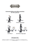
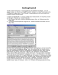
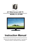
Commissioning Manual
FF 500 CNC
FF 500 CNC Commissioning Manual
1.
2.
Some generalities in advance…...................................................................................4
The technology of your FF 500 CNC at a glance .........................................................5
2.1.
A short overview of the mechanics: ..........................................................................5
2.2.
A short overview of the electronics: ..........................................................................6
3.
View of the machine with its elements..........................................................................8
4.
CNC control MCS with operating elements ..................................................................9
5.
Technical data ............................................................................................................10
5.1.
Milling machine:......................................................................................................10
5.2.
Drives of the tool axes ............................................................................................11
5.3.
Software and stepping motor controllers ................................................................11
5.4.
Further data ............................................................................................................12
5.5.
Milling cutter dimensions ........................................................................................12
6.
Scope of delivery ........................................................................................................12
7.
Basic tips on setting up and installing the machine ....................................................13
7.1.
Unpacking and setting up the machine ..................................................................13
7.2.
Connecting the cabling ...........................................................................................15
7.3.
Additional connection options .................................................................................16
8.
Installing the software.................................................................................................17
8.1.
Minimum hardware requirements ...........................................................................17
8.2.
Installation procedure .............................................................................................17
8.3.
Starting the software nccad7.5 ...............................................................................18
8.4.
Parameter settings .................................................................................................18
8.5.
The status display at the CNC control MCS ...........................................................18
8.6.
EMERGENCY stop / lock .......................................................................................19
9.
The program nccad 7.5 milling ...................................................................................20
9.1.
The integrated manual with the help system ..........................................................20
9.2.
The structure of the "Help topics" window ..............................................................21
9.3.
Search methods .....................................................................................................21
9.3.1 Contents .............................................................................................................21
9.3.2 Index ...................................................................................................................21
9.3.3 Search ................................................................................................................21
9.3.4 Explanation of the icons and the Status bar .......................................................22
9.4.
Online support ........................................................................................................22
10.
Important note for working in practice ........................................................................23
10.1.
Simple stopping of the machine and the Emergency-Off switch ........................23
10.2.
Safety stop, lock .................................................................................................23
10.3.
Direction of rotation switch..................................................................................23
10.4.
Room EMERGENCY Off ....................................................................................23
11.
First steps ...................................................................................................................24
11.1.
Simple test of the machine .................................................................................24
11.2.
Semi-automatic operation: Traversing the CNC axes with the cursor keys........25
12.
Working with the milling cutter....................................................................................26
12.1.
General information for working with milling cutter .............................................26
12.2.
Working with the drilling lever .............................................................................27
12.3.
Swivelling the milling head by its own transverse axis .......................................28
12.4.
Mounting the collet chucks .................................................................................28
12.5.
Changing the spindle speed ...............................................................................30
12.6.
Milling..................................................................................................................32
12.7.
Feed:...................................................................................................................32
13.
Accessories ................................................................................................................33
14.
Repair, Cleaning and Maintenance ............................................................................34
14.1.
In general............................................................................................................34
14.2.
Replacing the drive belt ......................................................................................35
14.3.
Adjusting the play of the cross table or Z carriage guides ..................................36
2 of 55
14.4.
Lubricating the machine......................................................................................36
14.5.
Cleaning and care...............................................................................................37
15.
Disposal......................................................................................................................38
16.
Errors and their removal .............................................................................................39
17.
Compilation of safety notes: .......................................................................................41
18.
EC Declaration of Conformity .....................................................................................43
19.
List of components and exploded views.....................................................................45
19.1.
General view.......................................................................................................45
19.1.1
General view exploded drawing and parts list ................................................45
19.1.2
Exploded drawing and parts list Assembly group 01:Z axis ...........................47
19.1.3
Exploded drawing and parts list Assembly group 02 Drive Y axis ..................49
19.1.4
Exploded drawing and parts list Assembly group 03 Drive X axis ..................51
19.1.5
Exploded drawing and parts list Assembly group 04: Milling head .................53
Ver. 1.0
16.09.08
3 of 55
1. Some generalities in advance…
Dear Customer!
The information given in this manual and the knowledge it conveys is indispensable
for the safe commissioning and the safe operation of the machine and the controls!
Before you set up and commission your machine, please read through the manual
and make sure you have understood everything. This is a very complicated device
which poses the danger of injury or can cause damage to property if handled
improperly.
Help to prevent this and familiarise yourself thoroughly with the machine and its
associated electronics without rushing matters.
The use of these instructions
-
makes it easier to become acquainted with the device,
prevents malfunctions due to improper handling, and
increases the service life of your device.
Always keep these instructions close to hand.
Only operate this device with exact knowledge of it and comply with these
instructions.
PROXXON will not be liable for the safe function of the device for:
-
handling that does not comply with the usual intended use,
other application uses that are not stated in these instructions,
disregard of the safety regulations.
You will not have any warranty claims for:
- operating errors,
- lack of maintenance.
For your safety, please comply with the safety regulations without fail.
Only use original PROXXON spare parts.
All rights reserved for further developments within the meaning of technical progress.
We wish you much success with the device.
4 of 55
2. The technology of your FF 500 CNC at a glance
Dear User,
With this FF 500 CNC vertical miller, you have acquired a powerful, precise
processing machine that fulfils the highest demands on ease of use, precision and
reliability. In the following, you will find explanations on some of the technical details:
2.1. A short overview of the mechanics:
The FF 500 CNC is a solidly constructed and carefully manufactured upright vertical
milling machine. The equipment compiled in a user-friendly manner and the
extraordinary quality of the design make the milling cutter a reliable partner for an
entire series of activities from the machining sector.
A heavy, rugged machine base ensures excellent stability and accommodates the
CNC-controlled cross table, traversable in two axes (diagonal (X axis) approx. 300
mm, deep (Y axis) 100 mm) as well as the sturdy and generously dimensioned
column made of high-strength aluminium continuous casting profile. Just like the
cross table, it is equipped with a dovetail guide which supports the carriage to
accommodate the milling head.
This carriage is also traversed by electronic control, and the traverse path (Z axis) is
approx. 220 mm. The milling head itself consists of the motor, the gearbox and the
spindle unit. If required, it can also be turned by 90° on each side and conveniently
clamped in any position with the toggle screw. Together with the drilling feed, this
makes slanted drilling possible, for example. The tool is held in one of the four
supplied collet chucks.
In addition, the milling head is equipped with a drill feed, which means that your
milling cutter can also be used for drilling work or for countersinking, for example.
The electrical system and the belt drive for power transmission are housed within the
gearbox. By simply shifting a Poly-V belt it is possible to adapt the spindle speeds to
different milling sizes and material-specific cutting speeds (six selectable speeds
from 180 - 2,500/min). The master device switch and the changeover switch for the
spindle direction of rotation are located at the front of the milling head.
The high-precision dovetail guides are adjustable for all axes in order to eliminate
possible play due to wear. You will find a dimensioned sketch of the machine
dimensions and the slot cross-sections (Fig. 1 and 2) on the left and at the end of the
text.
A comprehensive range of accessories is available in our assortment.
5 of 55
2.2. A short overview of the electronics:
The electrical control of the feeds of the three tool axes by computer
comprehensively expands the options of a conventional, i.e. manually controlled
processing machine:
The geometrical data of the desired work piece shape is constructed or programmed
by the NCCAD 7.5 software especially developed for this machine and can then be
reproduced automatically and any number of times on the FF 500 CNC.
How does this work in detail?
For a conventional tool machine, the carriage or the cross table would have to be
"cranked back and forth" manually using the handwheels in order to create the
desired contour from the blank with the miller or cutting chisel.
The feed movements of CNC machines are principally generated by electric motors
(so-called stepping motors with high resolution for the best processing accuracy and
reliability) and high-precision recirculating ball screws, which "translate" the rotation
of the motor shaft to a back-and-forth movement of the respective carriage.
However, someone must tell the motors how far they must traverse the tool and/or
carriage at what time and in which direction, so that the desired work piece shape
emerges.
This communication is assumed by the connected computer together with the
control. This control converts the "path information" given by the computer into
performance data for the motors.
The final work piece must be "constructed" in the computer first. Special computer
programs are available for this. After the part was created in the computer, the
programs can even calculate which motor on the machine must turn for how long and
how quickly so that the movement of the work piece holder corresponds exactly to
the one that would have had to been "cranked through" manually.
That is why the computer, the controller and the motors are constantly
communicating with each other: Meticulous adjustment of the components amongst
each other is thus decisive to achieve the optimum performance and offers the basis
for trouble-free operation.
To keep this state, certain knowledge of how the machine and the software are set
up is required on the one hand and the interaction of these components on the other.
That is precisely what this manual should convey at first: Not primarily the instruction
into the many "secrets" of the CNC program, but rather a solid knowledge base on
the commissioning of the machine.
Naturally, it is also necessary to generally occupy oneself with the possibilities of the
program and its structure, simply to be able to use the many possibilities, be more
efficient and to prevent dangerous situations from occurring.
We have integrated an "electronic manual" within the program just for that purpose. It
contains all the necessary information in a clearly structured and comprehensively
illustrated form and goes into exhaustive detail of the possibilities offered by the
program.
6 of 55
This is called up by clicking the "Help" menu and then clicking "Help Topics" in the
next window.
Finally, this manual can be used as a "Help" function to solve quite concrete and
current problems with an application, using the help of a sophisticated navigation
window.
This omits the annoying paging back and forth in a voluminous printed work: the
answers to specific problems are found quickly and precisely.
You will find notes on how to use the "Help" function further along in this manual.
Furthermore, we offer specific notes on what you can do to not only use the excellent
features of the machine, but to maintain it for a long time.
If a malfunction occurs despite all these things, the error table at the end of this
manual will provide some help. We will also offer direct assistance in case of
particularly stubborn cases.
The schematic illustration below shows the structure and the "interconnection" of the
individual components. The software that enables us to digitally construct the parts
and generate the "running commands" is installed on the computer at the bottom left.
Naturally, a notebook or laptop are more suitable as a "computing centre". These
stay mobile and it is not necessary to put a normal computer next to the machine in
your hobby basement or workshop.
The computer is connected by RS 232 connection to the control unit (we call it the
MCS multi-controller), and the electrical components of the machine are connected
to it in turn. All of the necessary connecting cables with matching plugs are supplied
and only need to be plugged in.
7 of 55
3. View of the machine with its elements
2
1
17
M
5
ate
ria
l
We
du rkzeu
rc
g
Ø hme
mm ss
e
r
3
4
-4
4-1
10 0
-2
20 0
-3
30 0
-40
Sta
hl
96
0
63
420
210
0
Alu
min
iu
18 m
8
96 0
630
210
0
21
0
9
Ku
ns
tsto
ff
18
8
96 0
630
210
0
21
0
6
25
11
18
14
12
7
8
23
19
13
10
22
24
20
16
15
21
Fig. 1: Overall view of the milling cutter
1.
2.
3.
4.
5.
6.
7.
8.
9.
10.
11.
12.
13.
Motor
14.
Covering cap
15.
On/Off switch
16.
Direction of rotation changeover 17.
switch
Table
18.
Knurled screw for covering cap
Swivel nut for collet chuck
Clamping screw for quill
Adjustable
scale
for
depth
adjustment
Adjustable scale for lateral traverse
path
Scale for angle adjustment
Drilling lever
Column
8 of 55
Z carriage/milling head fixture
Handwheel for X direction
Handwheel for Y direction
Handwheel for Z direction
19.
20.
21.
22.
Clamping
screw
for
height
adjustment
Work table (400 mm x 125 mm)
Screw holes for fastening
Base
Support
23.
Adjusting screws for X guide
24.
25.
Adjusting screws for Y guide
Adjusting screws for Z guide
4. CNC control MCS with operating elements
Fig. 2: Front side
Handwheel plug connections
Status indicator
"Emergency Stop" lock switch
Fig. 3: Rear
USB connection
(for programming the
controller hardware)
Connection for stepping
motor
Connection for
communications
cable to PC
25-pin plug for controlling
the additional functions
(coolant pump, or similar)
Mains
connection
Connection for
milling cutter
mains connection
Connection sockets for
the stepping motor
plugs
Master switch
9 of 55
5. Technical data
5.1. Milling machine:
Voltage:
220 - 240 Volt, 50/60 Hz
Capacity:
400 Watt
6 spindle speeds
shifting the belt:
by 180, 350, 550, 800, 1,300 and 2,500/min
Basic dimensions
see Fig. 2
Quill feed:
30 mm using drilling lever with scale ring (1
graduation line = 1 mm).
Cross table
solid, surface-milled cross table with 3
continuous T-slots for size 8 standard bricks
Slot clearance:
45 mm
Slot cross-section
see Fig. 3
Table size
400 x 125 mm
Tool holder
6, 8, 10 and 12 mm collet chucks (included in
delivery).
Milling head
can be pivoted to the left and right by 90° (with
degree graduation).
Extension (column outside approx. 125 mm
to centre of tool)
Column
of high-strength aluminium continuous casting,
extensively ribbed to achieve optimal strength
Noise generation
≤ 70 dB(A)
Vibrations
≤ 2.5 m/s²
Weight
approx. 50 kg
10 of 55
5.2. Drives of the tool axes
Spindle drive X axis
(Longitudinal drive, cross table):
Recirculating ball screw with 4 mm pitch, effective
diameter 12 mm. Stepping motor 2.2 A, holding torque
1.27 Nm, traverse path: approx. 290 mm
Spindle drive Y axis
(Transverse drive, lower carriage):
Recirculating ball screw with 4 mm pitch, effective
diameter 12 mm. Stepping motor 2.2 A, holding torque
1.27 Nm, traverse path: approx. 100 mm
Recirculating ball screw with 4 mm pitch, effective
Spindle drive Z axis
(Leading spindle, longitudinal drive, diameter 12 mm. Stepping motor 2.2 A, holding torque
support):
1.27 Nm, traverse path: approx. 220 mm
5.3. Software and stepping motor controllers
Power supply
Input: 230 Volt +-5%
Mains unit: output 35 V (included)
Power consumption
min 150 Watt
Gate
Serial interface
Stepping motor controller
Through CNC control unit (included) current control,
pulse width modulation
Current reduction during standstill, clocking independent
of PC, microstepping
- Connection cable to PC included
11 of 55
5.4. Further data
Ambient conditions:
5 - 40°C (Class 3K3), max.60% relative humidity
User group
Persons as of 14 years of age
5.5. Milling cutter dimensions
6. Scope of delivery
1
1
1
1
1
1
1
1
Qty.
Qty.
Qty.
Qty.
set
set
set
set
12 of 55
Milling cutter with attached stepping motors
CNC control unit MCS
CD with program software (including electronic manual)
Mains cable for CNC control unit MCS
of connecting cables for computer / CNC control unit MCS
of operating tools
of commissioning manual and safety regulations
of collet chucks Ø 6, 8, 10 and 12 mm incl. swivel nut
7. Basic tips on setting up and installing the machine
7.1. Unpacking and setting up the machine
Caution!
Do not insert the mains plug before completing the assembly work as the machine
could be switched on unintentionally. Risk of injuries!
Carefully unpack the individual components from the Styrofoam packaging. Please
check for completeness of the delivery by using the list in the chapter "Scope of
Delivery".
Caution! Please assemble the drilling lever (item 12 in the "Overall view of the milling
cutter) to the drilling lever shaft!
Caution!
Your milling machine weighs approximately 50 kg. Please do not attempt to lift the
machine out of the box by yourself or even set it up alone! Ask someone to help you,
otherwise you risk hurting yourself or damaging the machine.
The machine may only be set up and operated in dry and well-ventilated rooms. The
configuration of the components and its cabling is illustrated in the schematic figure
in Chapter 2.
The setup site must be level and sufficiently stable to absorb the vibrations that occur
during work. The machine must be fastened
to a fixed, level underlay using the drill
holes intended for this purpose.
Please make sure the mains cable is
outside the hazard area and cannot be
crimped or otherwise damaged.
1
For safe and precise work, it is mandatory to
fasten the machine onto a sturdy workbench or
similar working support, see figure at right.
There are two drill holes 2 for two M8
Allen screws on the right and left in the
machine base 1 for this purpose.
2
13 of 55
Please note:
At delivery, some of the blank metal parts of the machine are conserved with
corrosion protection. This protection is not intended as lubrication but only as
conservation and must be removed before first use, such as with a lint-free cloth
saturated with petroleum.
All guides must be checked, and in rare cases adjusted as necessary. (See chapter
"Maintenance").
The blank guides and spindles must then be oiled with suitable machine oil.
14 of 55
7.2. Connecting the cabling
How to connect the devices to each other is illustrated in the schematic sketch.
Caution!
Connect the mains cable to the CNC control MCS and to your computer at the very
last and make sure the mains switch at the rear of the CNC control is set to "O",
meaning switched off! Do not in any case switch on any electrical device, be it the
computer, the CNC control, or the machine itself before the connection of the cables
is completed!
The
connection
sockets on the CNC
control are all located
at the rear of the
housing:
The connection cable
of the three stepping
motors is inserted in
the provided sockets of
the CNC control. They
are
identified
accordingly as "X", "Y"
and
"Z"
of
the
respective CNC axes.
For your information:
The "implied" X axis is
horizontal
in
the
longitudinal direction of
the cross table, the Y
axis is also horizontal
but at right angles to
that, and the Z axis
describes the vertical
traversing of the milling head at the column.
The mains cable of the milling machine is inserted in the provided socket at the rear
of the CNC control. The spindle motor is switched on and off by the CNC programs.
Please leave the insertion of the mains plug of the computer and the CNC control in
the mains socket outlet for the very last.
The communications cable included in the delivery is used to connect the CNC
control to the control computer. It is inserted in the appropriate socket at the control
and connected to a serial interface at the computer.
These are often called "serial" or "COM" and usually have 9 pins. If the connection at
your computer has 25 pins instead of 9, you will need a corresponding adapter.
15 of 55
7.3. Additional connection options
Several additional functions can be electronically
actuated upon request, such as a coolant pump, working
light, or similar.
The inside of the control has centre-zero relays whose
connections can be executed through the 25-pin socket
at the rear of the control. Each relay has three pins that
are identified by the letters A, R and G. These letters
stand for:
A:
R:
G:
Make contact
Break contact
Common contact
The circuit design mode of operation is illustrated in the
picture on the right; both Relays 3 and 4 are available.
Ground
+ 24 Volt
Make contact
Common
Brake contact
16 of 55
8. Installing the software
8.1. Minimum hardware requirements
The NCCAD software is very comprehensive and powerful, therefore there are
certain minimum requirements towards the utilised control computer:
Simple operation and controller PC:
•
Windows 98/2000/XP
•
RAM: at least 16 MB
•
Free hard disk capacity: at least 60 MB
•
Graphics resolution at least 1024 x 768 pixel
Extended functionality (OpenGL simulation, manual control):
• Graphics resolution at least 1024 x 768 pixel
• Fast graphics card with chipset, at least Gforce4 or similar
8.2. Installation procedure
The software is included
on the enclosed CD.
After the CD is inserted
in the drive, the Explorer
will display the following
image:
Double-click
the
"Installation"
directory,
then
"English",
"01
Standard" and finally
"Setup Standard". This
starts the installation
procedure. Simply follow
the entry instructions.
The program is now
written to a directory
called "Kosy 75" that
contains the necessary
files. The program icon will be installed automatically to your desktop.
17 of 55
8.3. Starting the software nccad7.5
After the program was successfully installed, it can be started just as you are used to
from other applications on your computer. Simply select the "Start" button on the
screen with your cursor and select the desired file in the program title bar. It's even
easier if you simply click the program icon.
8.4. Parameter settings
The specific machine data (travel paths, limit values, working conditions, equipment,
etc.) are stored in the parameter files. These can be recognised by the ending "*.ini"
in the Windows Explorer.
Caution!
The values stored there are especially adapted to operation with the FF 500 CNC
and should not be changed without experience and knowledge of the program.
No changes may be made here especially before commissioning! False entries can
lead to system errors and dangerous operating states!
8.5. The status display at the CNC control MCS
There are three different coloured lights on the panel of the
CNC control; see picture. They indicate the operating status of
the CNC milling cutter.
•
Yellow:
Caution (Achtung) (in action) – command
execution running, even if the axis or spindle are not
currently moving. Do not reach into the CNC machine;
it is possible that the command "pause" is running
down and machining can continue at any time.
•
Green:
Free (Frei) (to receive commands) – Communications with the
PC is possible, commands can be received.
•
Red: Locked (Gesperrt) (or error) – The movement and command receipt of
the CNC machine are locked. This could be the case if the EMERGENCY stop
was activated, or if an error occurred in the system (e.g.: communications
error, PC no longer completely functional).
•
All: After the CNC milling cutter is switched on as a lamp test for a duation
of approx. 1 second.
18 of 55
8.6. EMERGENCY stop / lock
The EMERGENCY stop is used to lock the CNC milling machine
for command receipt and for command execution. Only the red
status lamp will light up in the "Lock" (Sperren) position. The lock
can be useful, for example, to prevent the execution of a
movement command that was entered unintentionally.
The lock is removed when the switch is set to "On" (Ein) and the
CNC milling cutter is ready for operation again. This is signalled by
the glowing green light.
19 of 55
9. The program nccad 7.5 milling
The program nccad 7.5 generates the
control program from the work piece
geometry
data,
co-ordinates
communications with the interface
control computer/CNC control, the
CNC axes, the generation of the step
pulses, etc. etc.
The control "translates" the signals
into commands for the stepping
motors.
The program offers manifold options
with a very large scope. Therefore,
one should consider that it takes some
time until one has a complete
overview of all the possibilities of the
program and can confidently move
between the many functions.
Much practice and naturally a bit of
patience is helpful before being able to use all the functions of the software.
For the beginning it is useful to know what the program can even do and that it owes
its capability in principle to several "individual" functions.
On the one hand, it is utilised to create a part in electronically drawn form (CAD), and
on the other hand it then generates the control commands from that geometry for the
control (CAM) which it then processes as electric signals for the motors of the spindle
drives.
9.1. The integrated manual with the help system
We deliberately refrained from using a
printed form of the manual and, as
already
mentioned
above,
have
consolidated the necessary contents in
a help function within the program itself.
A much more practical and neater
possibility than having to handle a
mountain of paper: The structure of the
topics has been optimised for an
intuitive and self-explanatory entry;
important things are recognised first and
navigation afterwards is effortless:
In the normal view, click on Help in the
menu line at the top right to start the
"Help Function". A submenu appears:
click here on Help topics and then the
Help window will appear.
20 of 55
9.2. The structure of the "Help topics" window
You will find an orientation window on the left with a few tools to help you quickly find
what you want to know and which offers you three different search methods. The
actual help text appears on the right.
9.3. Search methods
In the orientation section at the top you will find three tabs labelled "Contents"
(Inhalt), "Index" (Index) and "Search" (Suchen). Three different search principles are
possible:
9.3.1 Contents
The entire table of contents is illustrated as structure tree where one simply clicks on
the desired entry. Many others are tiered in several levels and branch out to several
alternatives, which can also be clicked. This gives the user all the possibilities to
specifically target the solution to his problem.
9.3.2 Index
This offers you the option of the Index search. Certain important keywords are
collected in an index directory. If a letter is entered in the entry line, the index register
moves up by the corresponding amount, and the term is isolated further for every
added letter. So-called generic terms offer additional entries illustrated in the
directory, inserted on the right. Simply click on one of the terms to open it.
9.3.3 Search
The search term is entered in a blank line and the "List Topics" button is pressed.
The hit (or hits) appear in the window and can be clicked. Important: Select the
options "Search for Previous Results", "Search for Similar Words", and "Only Search
for Titles".
21 of 55
9.3.4 Explanation of the icons and the Status bar
Select <File –CAD/CAM> in the menu. An
empty drawing surface appears with an
icon menu next to it.
Move the cursor over one of the icons and
wait for a moment without clicking any
icons. A brief explanatory text appears –
see figure at right. If you also press the
function key F1, a help window with a
detailed explanation to this icon will appear.
Please do pay attention to the status bar
afterwards! (See picture on the left)
There nccad is telling you which operating
steps to take next (e.g.: choose starting
point of a line).
9.4. Online support
In case of malfunctions that cannot be handled despite thorough perusal of this
manual as well as the utilisation of the help system, we would be happy to help you
directly.
Simply write an e-mail to the address [email protected]. You will receive a
response latest within 3 working days.
22 of 55
10. Important note for working in practice
10.1. Simple stopping of the machine and the Emergency-Off switch
Press any key of the PC keyboard to stop the carriage movement and to switch off
the milling machine. The system will then wait for further commands.
This "Keyboard Stop" is helpful during the test phase and for disruptions of machining
(e.g. wrong infeed, wrong feed).
10.2. Safety stop, lock
Press the "Lock" (Sperren) switch of the CNC control to stop the carriage movement
and to switch off the spindle. The system will not accept any further commands until
the switch/pushbutton is returned to the "ON" (Ein) setting.
10.3. Direction of rotation switch
Your CNC machine no longer has a separate mains switch as it is
controlled directly via control electronics. However, during normal
work, make sure that the direction of rotation switch of the
machine (shown in the figure on the right) is not in the "0" setting,
but is set to the desired direction of rotation. Otherwise the
machine will not start.
That is why it must not be set to "0" during a machining procedure
either, since the spindle movement would be interrupted.
10.4. Room EMERGENCY Off
Room EMERGENCY Off: An EMERGENCY Off switch that disconnects the power
supply in the entire room must be installed in the room where the machines are
operated. This red/yellow coloured mushroom-shaped pushbutton must be easily
accessible and arranged far enough away from the possible hazardous area.
23 of 55
11. First steps
At this point we would
like to reiterate that all
steps
relevant
to
commissioning
the
machine are found in the
"Help" function of the
program and it is vital to
familiarize oneself with
these functions before
the commissioning. The
figure on the right
illustrates the screen
view that you will see if
you
have
clicked
"Commissioning:
First
steps" in the structure
tree on the left under the
entry
"CNC
Milling
Machine". This explains
in great detail what you
need to know in order to
handle the machine.
11.1. Simple test of the machine
In the nccad menu "Machine",
select the option "Milling Cutter"
and observe the status display:
the lamps must flash briefly and
the green lamp must stay on. At
the same time, the "Manual
control" window must appear on
the screen – see figure at right.
Always
press
the
button
"Approach reference point" after
every program start as shown in
the figure.
A reference point approach of the
carriage is carried out with the
purpose of activating the position switches in the three axes. This is used for the
"definition of position" of the carriage: The control now knows exactly where the
carriage is and can now calculate the commands for the stepping motors accordingly.
24 of 55
If an error message appears instead of the
"Manual control" window, the interface may be
incorrectly set.
To remove the error, it is usually sufficient to
readjust the interface in the "Parameters"
menu. First click "Machine" and then "Edit
parameters".
The window shown in the figure on the right
appears. Select the serial port as shown (COM
1) and then try again.
The program must be ended first and then
restarted. If it still does not want to function,
please review the notes in the chapter "Errors
and their removal".
11.2. Semi-automatic operation: Traversing the CNC axes with the
cursor keys
Please note: This operation mode is just
possible to proceed with open “Manual
operation” window, as shown on the right. (Klick
“Machine” in the main menue, then “Milling
machine”, after that the window must appear)
The option of working in "Semi-Automatic" mode
is also available: The individual axes can be
traversed by pressing the cursor keys and the
page up and/or page down keys:
Pressing the cursor keys adjusts the cross table
in the level (i.e. the X and Y axes are addressed)
meaning precisely in the sense of direction in
which they are also arranged on the keyboard.
The milling head can be vertically adjusted (Z
axis) using the page up and/or page down keys:
Pressing the page up key will move the milling
head up, and pressing the page down key
moves it down.
25 of 55
12. Working with the milling cutter
12.1. General information for working with milling cutter
Caution!
Disconnect the mains plug before you do any adjustments or when exchanging tools!
Caution!
Please note that despite all the advantages for use in machine tools, the condenser
motor used here can become quite warm due to the construction type. This is not an
indication of a defect and can occur when the motor idles for a longer period of time
or runs under a very minor load. Please be sure to avoid these operating conditions
and do not allow your milling cutter to run on idle excessively.
Caution!
Please note:
There is always a potential risk of injuries emanating from all motor-driven or
manually driven parts from machine tools. Therefore, please ensure you always keep
sufficient distance and never reach into moving tools!
Never hold the tools with your hand - always tighten them properly!
Note!
The milling cutter is equipped with a so-called restart protection: In case of brief
voltage interruptions during operation, the milling cutter will not automatically restart
for safety reasons. After the correct voltage is present again, the milling cutter can be
started normally with the ON (Ein) button.
26 of 55
12.2. Working with the drilling lever
Please note:
Never actuate the drilling lever during CNC operation or even adjust it to a new
position! This could cause damage to the machine and/or the work piece!
While the milling cutter is operating, the milling head is traversed automatically with
the milling spindle, making the use of the drilling lever superfluous: The drilling
movements are performed with the Z axis.
However, for drilling work in semi-automatic mode, i.e. when working quasi manually
by pressing the cursor keys to adjust the axes, it is also possible to manually actuate
just the quill with the spindle using the drilling lever (e.g. if you wish to drill a hole
pattern in a plate, etc.). A milling head adjusted at a slant will be able to make slanted
drill holes.
1.
2.
3.
4.
5.
Release toggle screw 4.
Release Allen screw 5 at
scale ring 7 and set scale to
zero.
Re-tighten screw 5.
Set the desired height with
drilling lever 2.
Re-tighten toggle screw 4.
Ma
ter
ial
We
rk
urc zeug
Ø hme
mm ss
er
-4
4-1
10 0
20 20
-3
30 0
-40
Sta
hl
96
0
63
420
0
21
0
Alu
min
iu
18 m
8
96 0
630
210
0
21
0
Ku
ns
tsto
ff
18
8
96 0
630
210
0
21
0
3
5
2
4
7
27 of 55
12.3. Swivelling the milling head by its own transverse axis
To swivel the milling head by the transverse axis,
simply release Allen screw 1 and swivel the
milling head to the desired position. Set the
desired graduated number on scale 2 and retighten screw 1. The milling head can be 2
swivelled to every side by 90°: Important if drill
holes must be manufactured using the quill feed. 1
12.4. Mounting the collet chucks
Caution!
You must disconnect the plug from the power socket to prevent unintentional startup! Risk of injuries!
Caution!
• Never insert the collet chuck singly into the spindle receiver!
• Always engage the collet chuck in the swivel nut first!
• Always make sure that the collet chuck and the milling shaft have the
matching diameter!
Please note: In addition to the supplied collet chucks, we have further sizes available
in our accessories range. Please contact our Customer Service should you have any
further questions. You will find the postal address at the back of these instructions, or
simply write us an e-mail to [email protected].
28 of 55
1.
2.
3.
4.
5.
6.
7.
8.
9.
Ø
rch ug
m
mm ess
er
Release swivel nut 4 at the
Sta
hl
96
Alu
0
milling spindle 1.
63
mi
niu
420
0
18 m
21
8
0
Put the desired collet chuck
96 0
630
210
0
5 (see bottom image) by
21
0
hand in the swivel nut 4 and
allow to engage with slight
axial pressure at the
continuous groove.
Caution! The thinner end of
the collet chuck must point
up, as shown in the figure.
1
Insert swivel nut 4 with the
collet chuck in spindle 1
(see picture detail at right)
4
and tighten lightly by hand.
Insert shaft of tool 3 in the
collet chuck.
Use the supplied wrench to
tighten the swivel nut, as
shown in the figure.
To remove the collet chuck,
release swivel nut 4 and pull
out tool 3.
Now remove the swivel nut with collet chuck
completely out of the milling spindle.
Disengage the collet chuck with the supplied tube
section 6 by pressing on the cone of the collet chuck
and remove from the swivel nut.
-4
4-1
10 0
20 20
-3
30 0
-40
Ku
ns
tst
18 off
8
96 0
630
210
0
21
0
1
4
3
29 of 55
12.5. Changing the spindle speed
Setting the spindle speed is necessary so that the cutting speed of the tool can be
adapted to the characteristics of the material to be machined and to the tool
geometry.
Large tool diameters at equal rotational speed also mean a large circumferential
speed and thus potentially a too large cutting speed. Conversely, the same is also
true for small tool diameters.
This makes it necessary to be able to vary the rotational speed. To do so, a belt drive
guides the motor power at the milling cutter to the spindle. This is a two-stage
gearbox with an intermediate gear for general speed reduction and two ratchet
wheels with respectively different diameters in pairs. These are connected by two
poly-V belts that are excellently suited for this purpose due to their quiet running and
transfer characteristics. The respectively required spindle speeds can be realised by
shifting the belts. A total of 6 spindle speeds can be set: 180, 350, 550, 800, 1,300
and 2,500/min.
The sketch on the right shows the respective belt pulley combinations of the
individual rotational speeds; necessary rotational speeds for different milling cutter
sizes and materials can be read directly in the table on the gear case.
2500 / min
1300 / min
800 / min
550 / min
350 / min
180 / min
30 of 55
Caution!
Before working on the belt
drive, always disconnect the
plug from the power socket!
Risk of injuries!
1. Release knurled screw 1
and swing up the housing
cover.
2. Slightly release fastening
screws 4 (small detail)
and shift the housing
somewhat to the right
until the lower drive belt
3
relaxes.
1
3. Bring the lower V-belt 2
into the corresponding
position.
The
corresponding belt positions are shown in the previous graphics. However, you
can also use the sticker on the inside of the housing cover as orientation.
4. Shift the housing back to the left until the drive belts are properly tensioned and retighten the fastening screws 4.
5. Close the housing cover and retighten the knurled screw 1.
Caution!
The belt cover and/or housing cover
must always be closed during
operation!
2
2
4
31 of 55
12.6. Milling
Caution!
Always wear protective goggles during milling.
Comply with the safety regulations without fail!
8
6
5
The work piece to be processed must always be
securely fastened to the cross table! There are
various possibilities available to you: Clamping
jaws (e.g. 24 257 from PROXXON) and vices (e.g.
24 255 from PROXXON) are very well suited. The
cross section of the groove is shown in the image
on the right.
You will find examples for clamping devices and
accessories in our equipment brochure, on the
13,5
internet at www.proxxon.com, and together with
other valuable notes, in our "Manual for the Creative Modeller" (Art. No. 28 996; only
in German).
12.7. Feed:
During milling, make sure the feed always occurs against
the cutting direction of the milling cutter, see image at right.
32 of 55
13. Accessories
Commercially available milling cutters with a maximum shaft diameter of 12 mm and
a tool diameter of approx. 40 mm can be used. For an optimal working result, it is
necessary to adapt the milling cutter as well as the milling parameters (feed, milling
depth, rotational speed) to the working conditions and to make a choice from these.
Naturally, this includes observing the table on the V-belt cover of the milling cutter.
We recommend the milling inserts from our accessories program, such as the end
mill cutter set (2-5 mm) 24610 or - for larger work - the end mill cutter set (6-10 mm),
article no. 24620.
Gears with the module m=0.5 can be milled using the tooth form cutters from our
accessories program; teeth numbers from 12-54 can be realised.
You will find further suitable milling and drilling tools in PROXXON quality from our
comprehensive program in specialist shops. They will be able to recommend a
suitable PROXXON product for your special application case.
33 of 55
14. Repair, Cleaning and Maintenance
Caution!
Disconnect the mains plug before all repair and maintenance work!
14.1. In general
Please keep the machine clean and handle with care. Keep in mind that "healthy"
mechanics are decisive for the quality of the working result.
The guides play a very important role here: They are important machine elements
and must be handled with special care.
Cleaning the machine after every use and the regular application of oils and
lubricants is always a part of caring for the machine.
The CNC machine should always be in a clean condition, i.e. carefully cleaned after
every working stage.
Some elements affect the precision and work safety and must therefore be checked
regularly. Here the following checklist for this purpose:
•
•
•
•
Are the guides clean and dry?
Is the machine, and are especially its moving parts, free from processing
residues?
Are the fastening screws tight?
Alignment: Are the guides adjusted neatly?
If required, the following maintenance activities are necessary:
• Clean the machine (vacuum cleaner!) and rub dry
• Readjust the guides in case the carriages have play
• Rub guides and moving parts with acid-free oil.
If the CNC machine will be decommissioned for a longer period of time, it should be
stored in a dry room at a minimum temperature of 5°C.
A cover to protect from dust and environmental effects is sensible.
In case of a major repair, please send the machine back to us. The address is:
PROXXON G. m b. H.
Zentralservice
Im Spanischen 18-24
D-54518 Niersbach/Eifel, Germany
34 of 55
14.2. Replacing the drive belt
If the drive belts are worn, you
can replace them yourself. You
will receive spare belts from
PROXXON
Zentralservice
(address at the back of these
instructions).
1. Release knurled screw 1 and
swing up the housing cover.
2. Slightly release fastening
screws 4 and shift the housing
somewhat to the right until the
lower V-belt relaxes.
3. Unscrew the motor from the
screws 3.
4. Now, both belts can be
replaced. Please note: The
belts do not have the same
length! Do not mix up the belts!
5. Screw the motor back on.
Ensure correct belt tension.
6. Correctly position the lower V-belt 2
according to the desired rotational
speed. Use the sticker on the inside of
the housing as orientation.
7. Shift the housing back to the left until the
V-belts are properly tensioned and retighten the fastening screws 4.
8. Close the housing cover and re-tighten
the knurled screw 1.
3
1
2
2
4
35 of 55
14.3. Adjusting the play of the cross table or Z carriage guides
If the guide of a cross table or Z
carriage axis develops too much
play after some time, you can
readjust the play using the
adjusting screw 2. To do so,
release the counter nuts 1 and
evenly turn in all adjusting screws
until the play is eliminated. Then
retighten the counter nuts.
1
2
14.4. Lubricating the machine
After use, clean the cross table and milling cutter with a soft cloth or brush. Then
lightly oil the guides and distribute the oil by traversing the table.
Never clean the cross table with compressed air as the guides would be destroyed
by the entering swarf!
To guarantee the long service life of the milling cutter, please comply with the
lubrication schedule below (A: Oil before beginning any work / B: Oil monthly, please
note: The figure corresponds to the conventional version of the milling cutter, but the
lubricating points are appropriate). Only use acid-free machine oil from specialist
shops!
Grease or oil all parts according to the lubrication schedule. When oiling the sliding
surfaces, move the carriages back and forth by hand several times so that oil can run
into the guides.
A = Oil/lubricate before every use
B = Oil/lubricate monthly
The regular and careful lubrication will decisively reduce friction between two moving
parts and will thus contribute to a long service life of the guide and a good
mechanical condition of the machine.
36 of 55
To properly apply the lubricant, use an oil can or a lint-free cloth saturated with oil or
grease. Please, treat the guides and all moving and blank parts in the same manner.
Please, also comply with the instructions of the lubricant manufacturers!
B
B
A
A
A
A
A
14.5. Cleaning and care
Caution!
Always disconnect the mains plug before any cleaning, adjusting, maintenance or repair!
Risk of injuries!
Note:
The machine is primarily maintenance free. For a long service life, clean the device after
every use from swarf and other processing residues.
Make expedient use of a hand broom, a brush or a (lint-free) cloth. A vacuum cleaner
can also be recommended.
Please ensure that swarf does not get into the guides or other moving parts!
Therefore, never blow off the machine using compressed air: Dust and above all
swarf can be blown into guides or other moving parts and damage them!
When using cleaning agents, make sure the saturated wiping cloths are disposed of
in an environmentally-compliant manner. Do not dispose of in household waste.
37 of 55
15. Disposal
Do not dispose of the device or parts thereof in the household waste! The device contains
valuable substances which could be recycled. If you have questions concerning this topic,
please address your municipal disposal company or other appropriate municipal institutions.
38 of 55
16. Errors and their removal
Mains switch does Mains switch not switched on
not light up
Mains supply interrupted
Mains plug in control not properly inserted
Mains line-side fuse interrupted
(Subsequent error)
Red LED still lit 5 Switch (pushbutton) for EMERGENCY
sec after switching stop (lock) was activated
on
Installed microcontroller does not match
the software version
Red LED lights Switch (pushbutton) for EMERGENCY
during machining
stop (lock) was activated
Communications error (see below)
Connection to PC was interrupted
All 3 status indicator Switching the control on and off occurred
LEDs permanently too quickly in succession
lit (flash)
Message "Machine Switch (pushbutton) for EMERGENCY
not ready"
stop (lock) was activated
COM interface set incorrectly
CNC machine not switched on
Connecting cable between PC and
control is interrupted or not inserted
correctly
Wrong connecting cable (not the original
cable delivered by PROXXON GmbH)
Set interface is not available in PC
Change to "Manual COM interface for machine and mouse Allocate
a
non-identical
control" and then no are identical
interface to both
mouse function
Mains switch is list, LEDs are not lit,
stepping motors are not humming
Internal fuse is interrupted
External load of socket
function" is too great
"Additional
During
"Manual Position switch does not open
control", an axis
autonomously
moves away from Position switch mechanically destroyed
the machine zero
point
Switch
(pushbutton)
for
EMERGENCY stop (lock)
must be activated
Replace position switch
39 of 55
Communications
error or Time Out
Work piece
point is lost
40 of 55
Bad connection between PC and CNC
Repair
machine, COM interface defective
Sources of interference exist
External
sources
of
interference
(interfering
pulse, EMC-interferences)
Utilise original connecting cable
(Cable length max. 2m)
zero Machine zero point/reference point is not
approached
Incorrect zero point selected from table
Speed factors too high
Spindle contaminated
Mechanical stiffness of spindle
Feed in material too great
Speed of machining unit not co-ordinated
to tool, material and infeed
Mass to be moved is too great
Fastening screw of the axis to be moved
is too loose
First remove the causative
error.
Do not in any case set a
new work piece zero point.
Approach the machine zero
point by pressing the
"POS1" key. This reestablishes the initial work
piece zero point.
17. Compilation of safety notes:
As with any other machine, there are some things that need to be observed when
operating the CNC milling machine so that dangers to humans and the environment
cannot occur.
In this context, please also observe the separately enclosed pamphlet with the safety
notes.
Special noise protection
This can be achieved through ear protection, a protective
cell, or a closed room. Also, clamp the tools short so that
they do not vibrate so strongly
User group
Persons above the age of 14 may use the system;
instructions on safety and compliance with the safety
notes is always required.
Caution!
Risk of injuries!
Setting up the
workplace:
Always keep your fingers away from the rotating work
piece during milling! Never measure the work piece during
operation with a sliding calliper or similar device! Do not
process the work piece during operation with a rasp or
sandpaper!
No spatial narrowness
EMERGENCY Off pushbutton in the room
Vacuum cleaner, permanently installed
PC and machine next to each other
User group
Technically capable persons who are at least 14 years of
age.
Familiarize yourself using the documents or by being
instructed.
Machining unit
Due to the safety regulations, a machining unit for
clamping processing is delivered.
Changing work pieces
Please observe at all costs that the machine is protected
against unintentional actuation while changing the tools or
clamping work pieces in the respective clamping device!
When changing the tools, the mains power input for the machining unit must be
removed from the mains socket!
Clamp the milling cutter as short as possible!
Eye and
contact protection
Wear protective goggles in the immediate vicinity and
make sure that the chuck guard is in the correct position
when operating the machine.
41 of 55
Software safety measures:
Locking and stopping
the machine:
•
•
Machining, or movement, can be interrupted at any time
(software STOP):
By pressing any key of the alphabetic and numeric keypad or any mouse
button.
Activate the switch/pushbutton "Lock" (Sperren) at the CNC control MCS to
the "Lock" (Sperren) position.
42 of 55
18. EC Declaration of Conformity
We herewith declare in sole responsibility that the following designated product in the
design which we have marketed complies with the principle safety and health
requirements of the applicable EU Directive.
This declaration shall lose its validity if unauthorised changes were made to the
system.
Manufacturer:
Proxxon GmbH
Im Spanischen
D-54518 Niersbach/Eifel, Germany
Product designation
CNC vertical milling machine
Type designation
FF 500 CNC
Article number 24340
EU Low Voltage Directive
Applied standards:
2006/95/EC
DIN EN 61029-1 / 12.2003
EU-EMC Directive
Applied standards:
2004/108/EC
DIN EN 55014-1 / 06.2007
DIN EN 55014-2 / 08.2002
DIN EN 61000-3-2 /10.2006
DIN EN 61000-3-3 / 06.2006
EU Machinery Directive
Applied standards:
2006/42/EC
DIN EN 61029-1 / 12.2003
Date: 18.08.2008
Signature:
Dipl.-Ing. Jörg Wagner
PROXXON S.A.
Device Safety Division
43 of 55
44 of 55
19. List of components and exploded views
Please order spare parts in writing from PROXXON Zentralservice (address at the
back of these instructions).
19.1. General view
19.1.1
General view exploded drawing and parts list
ET No.:
Designation
24340
24340
24340
24340
24340
24340
24340
24340
-
01
02
03
04
05
06
07
08
Assembly group Z axis
Assembly group Y axis
Assembly group X axis
Milling head
Base
Column
Screw
Ruler
45 of 55
1
Ma
ter
ial
We
du rkzeu
rch g
m
Ø
mm ess
er
-4
4-1
10 0
20 20
-3
30 0
-40
Sta
hl
96
0
63
420
0
21
0
Alu
m
iniu
18 m
8
96 0
630
210
0
21
0
4
Ku
ns
tst
18 off
8
96 0
630
210
0
21
0
6
8
3
5
2
7
7
7
46 of 55
19.1.2
Exploded drawing and parts list Assembly group 01:Z axis
ET No.:
Designation
24340
- 01 - 01
Z threaded spindle
24340
- 01 - 02
Motor
24340
- 01 - 03
Lid for column
24340
- 01 - 04
Screw
24340
- 01 - 05
Toothed belt wheel
24340
- 01 - 06
Headless screw
24340
- 01 - 07
Toothed belt
24340
- 01 - 08
Toothed belt wheel
24340
- 01 - 09
Fitted key
24340
- 01 - 10
Nut
24340
- 01 - 11
Ball bearing
24340
- 01 - 12
Spindle nut mount Z axis
24340
- 01 - 13
Screw
24340
- 01 - 14
Screw
24340
- 01 - 15
Hood
24340
- 01 - 16
Screw
24340
- 01 - 17
Felt ring
24340
- 01 - 18
Mount
24340
- 01 - 19
Position switch
24340
- 01 - 20
Screw
24340
- 01 - 21
Z carriage
24340
- 01 - 22
Screw
24340
- 01 - 23
Cover plates
24340
- 01 - 24
Nut
24340
- 01 - 25
Headless screw
24340
- 01 - 26
Screw
24340
- 01 - 27
Adjusting plate
24340
- 01 - 28
Screw
47 of 55
16
15
7
14
6
10
5
14
8
11
14
14
11
3
9
2
4
4
19
27
18
20
19
1
13
28
17
12
21
22
26
25
24
23
48 of 55
19.1.3
Exploded drawing and parts list Assembly group 02 Drive Y
axis
ET No.:
24340
24340
24340
24340
24340
24340
24340
24340
24340
24340
24340
24340
24340
24340
24340
24340
24340
24340
24340
24340
24340
24340
24340
24340
24340
24340
24340
24340
24340
24340
24340
Designation
-
02
02
02
02
02
02
02
02
02
02
02
02
02
02
02
02
02
02
02
02
02
02
02
02
02
02
02
02
02
02
02
-
01
02
03
04
05
06
07
08
09
10
11
12
13
14
15
16
17
18
19
20
21
22
23
24
25
26
27
28
29
30
31
Motor
Screw
Motor mount Y axis
Coupling
Nut
Ball bearing
Spindle nut mount Y axis
Screw
Recirculating ball screw
Felt ring
Screw
Mount
Position switch
Lower carriage
Adjusting plate
Nut
Stud bolt
Screw
Adjusting plate
Position switch
Mount
Screw
Screw
Spindle nut mount X axis
Felt ring
Stop screw, base
Stop screw, carriage
Nut
Screw
Cable clamp
Screw
49 of 55
20 22 21
17 16 18
4 29 5
6
3
14
24
18 16 17 15
6
25
23
28
27
19
2
8
7
1
30 31
26
10
50 of 55
9
12 11 13
19.1.4
Exploded drawing and parts list Assembly group 03 Drive X
axis
ET No.:
24340
24340
24340
24340
24340
24340
24340
24340
24340
24340
24340
24340
24340
24340
Designation
-
03
03
03
03
03
03
03
03
03
03
03
03
03
03
-
01
02
03
04
05
06
07
08
09
10
11
12
13
14
Motor
Screw
Motor mount X axis
Coupling
Nut
Ball bearing
Milling table
Actuating plate
Screw
X recirculating ball screw
Ruler
Screw
Cable clamp
Screw
51 of 55
7
8 9
11
10
6
6
12
12 3 13 14 5
52 of 55
4
2
2
1
19.1.5
Exploded drawing and parts list Assembly group 04: Milling
head
ET No.:
Designation
24340 - 04 - 01
24340 - 04 - 02
24340
24340
24340
24340
24340
-
04
04
04
04
04
-
03
04
05
06
07
24340
24340
24340
24340
-
04
04
04
04
-
08
09
10
11
24340
24340
24340
24340
24340
24340
24340
24340
24340
24340
-
04
04
04
04
04
04
04
04
04
04
-
12
13
14
15
16
17
18
19
20
21
24340
24340
24340
24340
24340
24340
24340
24340
24340
24340
-
04
04
04
04
04
04
04
04
04
04
-
22
23
24
25
26
27
28
29
30
31
24340 - 04 - 32
24340 - 04 - 33
24340 - 04 - 34
Cover for gearbox
Rotational speed table
sticker
Locking ring
Intermediate belt pulley
Double-V belt
Sockets
Disc
24340 - 04
24340 - 04
- 35
- 36
Collet chuck 10 mm
Collet chuck 12 mm
24340
24340
24340
24340
24340
-
04
04
04
04
04
-
37
38
39
40
41
Axis
Hinge pin
Allen screw
Bearing plate for idler
wheel
Nut
Disc
Hexagon nut
Screw for mounting clip
Nut
Mounting clip for capacitor
Capacitor
Cover
Left-Right switch
Direction
of
rotation
sticker
Gearbox casing
Disc
Corrugated washer
Bearing
Locking ring
Helical spring
Spring plate
Disc
Hexagon screw
Quill
24340
24340
24340
24340
-
04
04
04
04
-
42
43
44
45
Main spindle
Headstock
Clamping screw
Retaining plate
Belt pulley for main
spindle
Double-V belt
Strain relief
Cable clip
Screw
24340
24340
24340
24340
24340
24340
24340
24340
24340
24340
-
04
04
04
04
04
04
04
04
04
04
-
46
47
48
49
50
51
52
53
54
55
Screw
Allen screw
Disc
Guide bush
Motor retaining plate
Headless screw
Motor belt pulley
Rating plate sticker
Motor
Belt drive sticker
24340
24340
24340
24340
24340
24340
24340
24340
24340
24340
-
04
04
04
04
04
04
04
04
04
04
-
56
57
58
59
60
61
62
63
64
65
- 66
Headless screw
Toggle
Right limit stop
Drilling lever sticker
Graduated collar
Screw
Drilling lever
Cap
Shaft
Graduated
scale
sticker
Spring pin
- 67
- 68
Left limit stop
Mains cable
Swivel nut for spindle 24340 - 04
(including tube section,
not pictured)
Collet chuck 6 mm
24340 - 04
Collet chuck 8 mm
24340 - 04
53 of 55
1
Material
Werkzeug
durchmesser
Ø mm
2
Ma
ter
Kunststoff
Stahl
–
–
–
–
–
–
–
–
–
–
–
–
–
Aluminium
–
55
–
–
–
–
–
i
al
We
r
dur kzeug
c
–
Ø m hmes
m ser –
–
––
––
––
Sta
h
–
–
–
–
l
Alu
m
iniu
–
–
–
–
–
m
Ku
ns
–
–
–
–
–
tst
off
54
3
53
4
52
5
51
6
7
47
8
50
9
49
48
47
10
11
12
12
13
14
45
44
67
66
41
16 15
19
40
20
39
38
21 22
26
61
56
37
27
28
26
29
30
33-36-
31
32
25
62
58
23
24
25
54 of 55
65 64 63
43
42
18 17
68
46
57
59 60
Your device is not working properly?
Then please, read through the operating instructions once more.
If the device is actually defective, then please send it to:
PROXXON Zentralservice
D-54518 Niersbach/Eifel, Germany
We will respond promptly and reliably! You can also use this address to order any
necessary spare parts.
Important:
A brief description of the error will help us respond even quicker. For returns within
the period of warranty, please, include your proof of purchase.
Please, return the device in its original packaging!
This will help prevent damages during transportation!
All rights reserved for modifications within the meaning of technical progress.
55 of 55