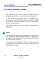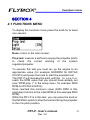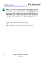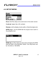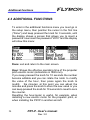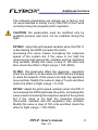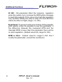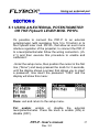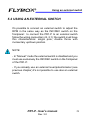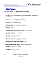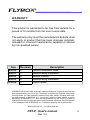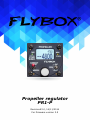
1
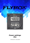
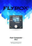
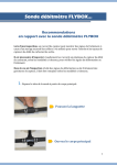
Flybox
®
Flybox
®
Propeller regulator
PR1-P
Revision#3.0, 14/11/2014
PR1-P
- User’sversion
manual
For firmware
3.5
Rev. 3.0
Page intentionally left blank
SECTIONS
MECHANICAL INSTALLATION
ELECTRICAL INSTALLATION
OPERATING INSTRUCTIONS
INSTRUMENT SETTINGS
USE WITH EXTERNAL COMMANDS
TECHNICAL SPECIFICATIONS
Flybox®
Introduction
Thank you for purchasing a Flybox® product. We hope
it fully satisfy you and makes your flights pleasant and
secure.
Developing PR1-P, our intent was to create a compact
and lightweight propeller controller, easy to install and
use.
SYMBOLS USED IN THE MANUAL
NOTE: Used to highlight important informations.
CAUTION: Used to warn the user and indicate a potentially
hazardous situation or improper use of the product.
WARNING: Used to indicate a dangerous situation that can
cause personal injury or death if the instruction is
disregarded.
PR1-P - User’s manual
Rev. 3.0
Flybox
®
Important notices & warnings
NOTE: Keep this manual in the aircraft.
This document must accompany the instrument in the event
of change of ownership.
NOTE: This device is intended for installation onto non type
certified aircraft only, because it has no aviation certifications.
Refer to your local aviation authorities to check if this device
may be installed in your aircraft.
CAUTION: Read entirely this manual before installing the
instrument in your aircraft, and follow the installation and
operating instructions described here.
CAUTION: The pilot must understand the operation of this
instrument prior to flight, and must not allow anyone to use
it without knowing the operation. Don't use this instrument
in flight until you are sure of the correct operating of the same.
CAUTION: When the installation is finished you must do a
test, prior to flight, switching on all the possible source of
electric noise and checking the properly operation of this
instrument.
CAUTION: The software of this instrument can be subject to
change, update, addition or removal of functions, so also the
operating mode of the instrument can be subject to change.
Always refer to the installation and operating manual updated
with the software version used in your instrument. To
obtain updated manuals, please visit www.flyboxavionics.it.
PR1-P - User’s manual
Rev. 3.0
Important notices & warnings
Flybox®
CAUTION: Using this instrument over the maximum
allowable ranges can cause malfunction or wrong indications.
CAUTION: the EFC-P must be turned off in case of start with
booster. open the corresponding breaker before starting.
warranty shall not apply for damage to the EFC-P for this
reason.
WARNING: The PR1-P is directly connected to the propeller
pitch actuator: the non-respect of the notices above or a
damage to the PR1-P may result in unexpected pitch changes.
WARNING: Responsibility for installation lies entirely with the
installer. Responsibility for operations lies entirely with the
operator. Responsibility for any calibration, settings or any
other customization lies with the person performing these
operations.
IMPORTANT: If you do not agree with the notices above
do not install this instrument in your aircraft, but return
the product for a refund.
Microel s.r.l. reserves the right to change or improve its
products. Information in this document is subject to changes
without notice.
PR1-P - User’s manual
Rev. 3.0
Flybox
®
Index
INDEX
SECTION 1 - Mechanical installation
1.1 - Mechanical installation …….……………………………..
8
SECTION 2 - Electrical installation
2.1 - Electrical installation …….………..………………….….. 10
2.2 - Panel indicators and commands ..…………………….….. 13
2.3 - Wiring check ……….….……………….…………….…... 14
SECTION 3 - Operating instructions
3.1 - Use of the instrument …….….…..………….…………….
3.2 - Use in “Constant speed” mode .………….….…………….
In case of failure or emergency ……….…….………..….
3.3 - Use in “Manual” mode .………….………….…………….
16
17
19
20
SECTION 4 - Instrument settings
4.1 - Functions menu .…..….….……….……..….……………. 21
4.2 - Setup menu .…….……………….………….……………. 23
4.3 - Additional functions …….……….………….……………. 24
SECTION 5 - Use with external commands
5.1 - Using an external potentiometer or the
Flybox® lever mod. PR1PL .……………………………. 27
5.2 - Using an external switch …………………….……………. 29
SECTION 6 - Technical specifications ……..…….……………. 30
Warranty …….…………………………………….……………. 31
PR1-P - User’s manual
Rev. 3.0
Flybox®
Mechanical installation
SECTION 1
1.1 MECHANICAL INSTALLATION
The PR1-P fits in a standard 2 1/4” panel cutout; it's
recommended to choose a position that permits optimal
display visibility.
It's furnished with four M4 screws to install it to the panel,
if you use other screws consider that the maximum thread
length is 15mm (see following picture).
8
PR1-P - User’s manual
Rev. 3.0
Flybox
®
Mechanical installation
All dimensions are in millimeters
PR1-P - User’s manual
Rev. 3.0
9
Flybox®
Electrical installation
SECTION 2
2.1 ELECTRICAL INSTALLATION
On the back of the FC1 there is a 15-pole male connector; it
is also furnished with the corresponding 15-pole female
connector, to be wired as follows:
15-pole female connector, view from wiring side
10
PR1-P - User’s manual
Rev. 3.0
Flybox
®
Electrical installation
Connector pinout:
1= +12V Main supply
2= GND Main supply
3= Motor out (+)
4= POT + (positive) for external lever/potentiometer
(optional)
5= “INC EXT” signal for external INC/DEC switch
(optional)
6= “DEC EXT” signal for external INC/DEC switch
(optional)
7= not used/reserved
8= GND for external INC/DEC switch (optional)
9= not used/reserved
10= POT - (negative) for external lever/potentiometer
(optional)
11= Motor out (-)
12= POT C (cursor) for external lever/potentiometer
(optional)
13= not used/reserved
14= not used/reserved
15= RPM input signal (minimum signal voltage: 10V)
PR1-P - User’s manual
Rev. 3.0
11
Flybox®
Electrical installation
NOTE: Insert an adequate circuit breaker to the power
lead, depending on the current consumption of the
propeller motor (MAX 7.5 A).
Use avionic cable. Use shielded cable to connect an
external lever or potentiometer.
Take care to properly insulate any exposed wire, to avoid
short circuit between any of the wires.
CAUTION: Voltage peaks that exceeds the operating limits
on the supply line (20V) can damage the device.
CAUTION: The PR1-P must be turned off in case of start
with booster. Open the corresponding breaker before
starting.
12
PR1-P - User’s manual
Rev. 3.0
Flybox
®
Indicators & commands
2.2 PANEL INDICATORS AND COMMANDS
Max pitch
LED
Min pitch
LED
Operating
mode
switch
INC/DEC
switch
Knob with
pushbutton
The knob with pushbutton can be rotated (for example to
increment or decrement the RPM) or pressed like a
pushbutton (for example to enter in the menu or in the
various settings).
NOTE: The operating mode switch has a safety lock to
avoid accidental operation: it must first pulled on the
outside and then moved to the desired position.
PR1-P - User’s manual
Rev. 3.0
13
Flybox®
Wiring check
2.3 WIRING CHECK
Before using the PR1-P in flight for the first time you must
execute this checklist (with the engine turned off):
● Turn-on the PR1-P.
● Put the operating mode switch in the “Manual” position.
● Press the “INC/DEC” switch in the “INC” position (increment
RPM) and check that the propeller pitch decrease; check
also that the “Min pitch” LED will go on when the propeller
reach the min pitch stop.
If the propeller pitch change in the wrong direction
(towards the max pitch) you must invert the two motor out
cable (Motor+ and Motor-).
● Press the “INC/DEC” switch in the “DEC” position
(decrement RPM) and check that the propeller pitch
increase; check also that the “Max pitch” LED will go on
when the propeller reach the max pitch stop.
● Turn-on the engine and execute a propeller/regulator test
(see the function “Prop test” in chap.4.1).
NOTE: Perform this wiring check after every modifications
or maintenance of the propeller system to verify that all
connections are restored correctly.
14
PR1-P - User’s manual
Rev. 3.0
Flybox
®
Wiring check
NOTE: Refer to the propeller constructor's manual if you need
to adjust the mechanical min and max pitch stop of the propeller.
NOTE: PR1-P works only with this type of propellers:
PR1-P - User’s manual
Rev. 3.0
15
Flybox®
Use of the instrument
SECTION 3
3.1 USE OF THE INSTRUMENT
The PR1-P has two operating modes: “Constant speed” and
“Manual”: you can select the operating mode using the
corresponding switch on the frontpanel.
For normal operations use always the “Constant speed”
mode; the “Manual” mode must be used in case of emergency
or failure of the PR1-P because it exclude the electronic
system and drive directly the pitch motor using the INC/DEC
switch.
At startup the display briefly shows the software version, then
it appear the main screen (see next chapter) or the
“MANUAL” indication if the operating mode switch is in the
“Manual” position.
16
PR1-P - User’s manual
Rev. 3.0
Flybox
®
Use in “CONSTANT SPEED”
3.2 USE IN “CONSTANT SPEED” MODE
ACTUAL RPM: Shows the actual
RPM (measured RPM) of the engine.
INTENDED TARGET RPM: Shows
the desired RPM that the engine must
keep.
At startup, the target RPM are set to 5700 (with factory
settings, except if you are using an external potentiometer).
To change the target RPM you can use either the knob or
the INC/DEC switch (INC to increment the RPM and DEC to
decrement the RPM).
In both case the increment/decrement can be in step of
10,25,50 or 100 RPM, depending on the setting “RPM step”
in the setup menu (see item “RPM step” in the “Setup menu”).
PR1-P - User’s manual
Rev. 3.0
17
Use in “CONSTANT SPEED”
Flybox®
The PR1-P, when properly installed and configured, can always
be used in “Constant speed” mode, by the starting, take-off,
landing, making sure to always perform the following checks:
● Before the take-off:
- Perform a propeller test as explained in chap. 4.1, “Prop
test” function.
- Check that the min pitch green led is turned on.
- Check that the target RPM are set to the takeoff value.
● During the take-off:
- Check that the engine takes the required RPM.
● During the climb:
- Engine RPM and speed checks.
● During the flight:
- Set the desired RPM by turning the knob or using the
INC/DEC switch.
● Before landing:
- Set the target RPM to the takeoff value.
If you have any doubt about using a constant-speed variable
pitch propeller, contact a qualified instructor.
18
PR1-P - User’s manual
Rev. 3.0
Flybox
®
Use in “CONSTANT SPEED”
IN CASE OF FAILURE OR EMERGENCY:
If during any phase of flight you notice that the PR1-P don't
adjust correctly the propeller pitch turn immediately the
operating mode switch to the “Manual” position; this switch
has a safety lock to avoid accidental operation: it must first
pulled on the outside and then moved to the desired
position.
PR1-P - User’s manual
Rev. 3.0
19
Flybox®
Use in “MANUAL”
3.3 USE IN “MANUAL” MODE
The “Manual” mode must be used only when testing the
propeller system and in case of failure or emergency.
In this mode the propeller pitch is adjusted using
exclusively the INC/DEC switch: press in the “INC” position
to increment the engine RPM and press in the “DEC”
position to decrease it.
The display shows only a screen with a fixed “Manual”
indication.
NOTE:
- To adjust the propeller pitch in “MANUAL” mode you must
use exclusively the INC/DEC switch on the PR1-P
frontpanel, because the knob and the external switch/lever
(if presents) has no effect.
- If you take-off in “MANUAL” mode, it's your task to rev
the engine with the throttle lever and pay attention to not
overspeed the engine.
20
PR1-P - User’s manual
Rev. 3.0
Flybox
®
Functions menu
SECTION 4
4.1 FUNCTIONS MENU
To display the functions menu press the knob for at least
one second.
Done: return to the main screen.
Prop test: execute a self-test (varying the propeller pitch)
to check the correct working of the system
regulator/propeller.
To execute this test you must rev up the engine to an
appropriate value (for example 5000RPM for ROTAX
912/914) and press the knob to start the propeller test.
The PR1-P will increase the pitch until the p r o p e l l e r
reach the RPM value that you should have already set
(see “RPM prop t.” in the setup menu, for example 4000
RPM for ROTAX 912/914)
Once reached this minimum value (4000 RPM in this
example) it returns to the initial RPM (in this example 5000
RPM).
While the PR1-P is in this test, you can press the knob or
the INC/DEC switch to stop the test and bring the propeller
to the min pitch position.
PR1-P - User’s manual
Rev. 3.0
21
Flybox®
Functions menu
NOTE: To prevent accidental activation of the test when in flight
this function is removed after the takeoff (the PR1-P consider
a takeoff when the engine meets or exceeds 4000 RPM for 30
seconds). So if you perform an engine test above 4000 RPM
and longer than 30 secs you can’t run the “Prop test”
automatically but you have to manually test the propeller , by
varying the pitch with the knob or with the INC/DEC switch.
Light: Turns on/off the display backlight.
Setup: enter the setup menu (see next chapter).
22
PR1-P - User’s manual
Rev. 3.0
Flybox
®
Setup menu
4.2 SETUP MENU
Done: Exit the setup menu and return to the main screen.
Contrast: adjust the LCD contrast.
Display: set the display mode (white or black background).
RPM prop t.: set the RPM that the engine must reach in
the propeller test.
RPM step: set the minimum step when changing the RPM
with the knob or the INC/DEC switch. The step value can
be 10,25,50 or 100 RPM.
PR1-P - User’s manual
Rev. 3.0
23
Flybox®
Additional functions
4.3 ADDITIONAL FUNCTIONS
To enter in the additional functions menu you must go in
the setup menu, then position the cursor in the first line
(“Done”) and keep pressed the knob for 3 seconds, until
the display shows a screen that allows you to insert a
password: now insert the password “2010” and the display
will show this menu:
Done: exit and return to the main screen.
Hour: Shows the effective operating time of the propeller
pitch electric motor (indications in hhhh:mm).
If you keep pressed the knob for 10 seconds the number
become editable and you can rotate the knob to modify
the value of the hour, then press again the knob to
modify
the minutes; at this point you can adjust the
minutes and press the knob to store the new value or you
can keep pressed the knob for 10 seconds to reset to zero
the counter.
Resetting the hour-meter is useful, for example, when
installing a new electric motor for the propeller pitch, or
when installing the PR1P in another aircraft.
24
PR1-P - User’s manual
Rev. 3.0
Flybox
®
Additional functions
The following parameters are already set in factory and
it's recommended to modify it only if the PR1-P don't work
correctly during the propeller pitch regulation.
CAUTION: the parameters must be modified only by
qualified persons and must not be modified during the
flight.
KP DEC: adjust the pitch speed variation when the PR1-P
is decreasing the RPM (increase the pitch).
Increasing this value means increasing the response
speed of the system but if the value is too high the
response become inaccurate, unstable and the regulation
may oscillate. Modify this value in step of 100 units and
then check the effect in flight (range = 100~5000).
KI DEC: this parameter affect the response regulation
when the system try to decrease the RPM without manage
to reach the setpoint. If this value is too high the regulation
may oscillate. Modify this value in step of 5 units and then
check the effect in flight (range = 0~100).
KP INC: adjust the pitch speed variation when the PR1-P
is increasing the RPM (decrease the pitch). Increasing this
value means increasing the response speed of the system
but if the value is too high the response become
inaccurate, unstable and the regulation may oscillate.
Modify this value in step of 100 units and then check the
effect in flight (range = 100~5000).
PR1-P - User’s manual
Rev. 3.0
25
Flybox®
Additional functions
KI INC: this parameter affect the response regulation
when the system try to increase the RPM without manage
to reach the setpoint. If this value is too high the regulation
may oscillate. Modify this value in step of 5 units and then
check the effect in flight (range = 0~100).
Dead band: To prevent continuous actions of the propeller
pitch electric motor it's possible to use this parameter: if
the difference between the measured RPM and the
intended RPM is lower than this parameter there will be
no pitch regulation. (Default value=20, range=0~100).
RPM in filter: Default value=5, range=1~100. Don’t
modify this parameter, consult the constructor.
26
PR1-P - User’s manual
Rev. 3.0
Flybox
®
Using an external pot.
SECTION 5
5.1 USING AN EXTERNAL POTENTIOMETER
OR THE Flybox® LEVER MOD. PR1PL
It's possible to connect the PR1-P to an external
potentiometer (with resistance from 5 to 10 kohm) or to
the Flybox® lever mod. PR1PL, that allow an even more
intuitive regulation of the propeller; to connect the PR1-P
to a lever/potentiometer follow the wiring connection (ch.
2.1) and then execute this procedure to enable and
calibrate it:
- Enter the setup menu, then position the cursor in the first
line (“Done”) and keep pressed the knob for 3 seconds,
until the display shows a screen that allows you to insert
a password; now insert the password “1024” and the
display will show this menu:
Done: exit and return to the setup menu.
Pot enable: enable or disable the external
lever/potentiometer. Press the knob to enable (ON) or
disable (OFF).
PR1-P - User’s manual
Rev. 3.0
27
Flybox®
Using an external pot.
Pot min: Position your lever/potentiometer to the minimum
value (min. RPM value) and press the knob to allow the
PR1-P store this position.
RPM min: Insert here the RPM indicated in your
lever/potentiometer at the min RPM position (the same
position stored in the previous step).
Pot max: Position your lever/potentiometer to the
maximum value (max. RPM value) and press the knob to
allow the PR1-P store this position.
RPM max: Insert here the RPM indicated in your
lever/potentiometer at the max RPM position (the same
position stored in the previous step).
Now your lever/potentiometer is correctly calibrated and
you can exit from the menu (click on “Done”).
NOTE:
- In “Constant Speed” mode: enabling the external
lever/potentiometer will disable the knob and the INC/DEC
switch on the frontpanel, so the RPM adjustment is done
exclusively by the lever/potentiometer.
- In “Manual” mode: the external lever/potentiometer will
be disabled and you must use exclusively the INC/DEC
switch on the frontpanel of the PR1-P.
28
PR1-P - User’s manual
Rev. 3.0
Flybox
®
Using an external switch
5.2 USING AN EXTERNAL SWITCH
It's possible to connect an external switch to adjust the
RPM in the same way as the INC/DEC switch on the
frontpanel: to connect the PR1-P to an external switch
follow the wiring connection (ch. 2.1); the switch must have
this characteristics: single pole, double throw with
momentary up/down position.
NOTE:
- In “Manual” mode the external switch is disabled and you
must use exclusively the INC/DEC switch on the frontpanel
of the PR1-P.
- If you already use an external lever/potentiometer (see
previous chapter) it's not possible to use also an external
switch.
PR1-P - User’s manual
Rev. 3.0
29
Technical specifications
Flybox®
SECTION 6
6.1 TECHNICAL SPECIFICATIONS
● Graphic LCD with backlight and coated glass, dimensions
29x18mm.
● Standard mounting 2 1/4” (57mm).
● Anodized aluminium case.
● Dimensions: 60.0 x 60.0 x 52.6 mm.
● Weight: 190 g.
● Operational temperature range: -10 ~ +70°C.
● Supply voltage: 11 ~ 20 V=.
● Supply current: 100mA.
● Maximum motor supply current: 7 A .
● Minimum RPM voltage signal: 10 V.
● Measurable RPM range: 1000 to 8000 RPM.
● RPM Resolution: 10 RPM.
● RPM Accuracy: 0.02%.
30
PR1-P - User’s manual
Rev. 3.0
Flybox
®
WARRANTY:
This product is warranted to be free from defects for a
period of 12 months from the user invoice date.
The warranty only cover the manufacture's defects; shall
not apply to product that has been improper installed,
misused or incorrect maintenance, repaired or altered
by non-qualified person.
Date
09/2010
09/2011
10/2012
09/2013
11/2014
Revision
26
27
28
29
30
Description
Updated installation notes
Updated wiring installation
General revision
Updated wiring installation
Layout update
WARNING: All photos, data, drawings, instruments layouts, technical solutions and
data representation you find in this document or watching at Flybox® instruments
working and/or you can access by means of any other media, including web sites,
are sole property of MICROEL s.r.l., cannot be copied or imitate without a written
permission of MICROEL s.r.l. itself and are protected by law, even by means of
extended international copyright and/or specific patents deposited. Any infringement
of this statement and of MICROEL s.r.l. intellectual property will be prosecuted.
©2014 Microel s.r.l. – all rights reserved.
PR1-P - User’s manual
Rev. 3.0
31
MICROEL s.r.l.
Via Mortara 192-194
27038 Robbio (PV) - ITALY
Tel +39-0384-670602 - Fax +39-0384-671830
www.flyboxavionics.it