1
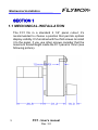
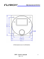
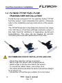
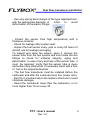
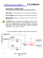
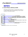
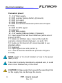
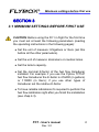
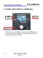
FLYBOX
®
Flybox
®
Fuel Computer
FC1
Revision#3.0, 25/11/2014
FC1
- User’s manual
For firmware
version 2.4
Rev. 3.0
Page intentionally left blank
SECTIONS
MECHANICAL INSTALLATION
ELECTRICAL INSTALLATION
OPERATING INSTRUCTIONS
INSTRUMENT SETTINGS
TECHNICAL SPECIFICATIONS
FLYBOX®
Introduction
Thank you for purchasing a Flybox® product. We hope
it fully satisfy you and makes your flights pleasant and
secure.
Developing FC1, our intent was to create a compact and
lightweight fuel computer, easy to install and use.
SYMBOLS USED IN THE MANUAL
NOTE: Used to highlight important informations.
CAUTION: Used to warn the user and indicate a potentially
hazardous situation or improper use of the product.
WARNING: Used to indicate a dangerous situation that can
cause personal injury or death if the instruction is
disregarded.
FC1 - User’s manual
Rev. 3.0
FLYBOX
®
Important notices & warnings
NOTE: Keep this manual in the aircraft.
This document must accompany the instrument in the event
of change of ownership.
NOTE: This device is intended for installation onto non type
certified aircraft only, because it has no aviation certifications.
Refer to your local aviation authorities to check if this device
may be installed in your aircraft.
CAUTION: Read entirely this manual before installing the
instrument in your aircraft, and follow the installation and
operating instructions described here.
CAUTION: The pilot must understand the operation of this
instrument prior to flight, and must not allow anyone to use
it without knowing the operation. Don't use this instrument
in flight until you are sure of the correct operating of the same.
CAUTION: When the installation is finished you must do a
test, prior to flight, switching on all the possible source of
electric noise and checking the properly operation of this
instrument.
CAUTION: The software of this instrument can be subject to
change, update, addition or removal of functions, so also the
operating mode of the instrument can be subject to change.
Always refer to the installation and operating manual updated
with the software version used in your instrument. To
obtain updated manuals, please visit www.flyboxavionics.it.
FC1 - User’s manual
Rev. 3.0
Important notices & warnings
FLYBOX®
WARNING: This instrument should never be used as a
primary instrument to determine the fuel tanks level; always
refer to the original fuel level indicators of your aircraft.
WARNING: Responsibility for installation lies entirely with the
installer. Responsibility for operations lies entirely with the
operator. Responsibility for any calibration, settings or any
other customization lies with the person performing these
operations.
IMPORTANT: If you do not agree with the notices above
do not install this instrument in your aircraft, but return
the product for a refund.
Microel s.r.l. reserves the right to change or improve its
products. Information in this document is subject to changes
without notice.
FC1 - User’s manual
Rev. 3.0
FLYBOX
®
Index
INDEX
SECTION 1 - Mechanical installation
1.1 - Mechanical installation …….……………………………..
1.2 - Flybox TFTHP fuel flow transducer installation …………
8
10
SECTION 2 - Electrical installation
2.1 - Electrical installation …….………..………………….…..
13
SECTION 3 - Operating instructions
3.1 - Minimum settings before first use …….….………..…..… 15
3.2 - Panel indicators & commands .…………………………… 16
3.3 - Use of the instrument .……………………………….…… 17
SECTION 4 - Instrument settings
4.1 - Functions menu .…..….….……….………….…..……….
4.2 - Setup menu .….….………….…………..….………….….
4.3 - Fuel flow transducer calibration …………….……………
21
24
27
SECTION 5 - Technical specifications …….………….……….
29
Warranty …….………………………..………….…………….
30
FC1 - User’s manual
Rev. 3.0
FLYBOX®
Mechanical installation
SECTION 1
1.1 MECHANICAL INSTALLATION
The FC1 fits in a standard 2 1/4” panel cutout; it's
recommended to choose a position that permits optimal
display visibility. It's furnished with four M4 screws to install
it to the panel, if you use other screws consider that the
maximum thread length inside the FC1 panel is 15mm (see
following picture).
8
FC1 - User’s manual
Rev. 3.0
FLYBOX
®
Mechanical installation
All dimensions are in millimeters.
FC1 - User’s manual
Rev. 3.0
9
Fuel flow transducer installation
FLYBOX®
1.2 FLYBOX TFTHP FUEL FLOW
TRANSDUCER INSTALLATION
If with the fuel computer FC1 it's used the Flybox TFTHP
fuel flow sensor, read completely this section, otherwise
refer to the installation and use instructions of the sensor
used.
The TFTHP flowmeter is developed to measure low range
(3.6~120 l/hour) of fuel flow with high resolution output. It
has high chemical resistance to aggressive liquids and
hydrocarbons. The case can be opened for periodic
monitoring and eventual replacement of the tube.
RECOMMENDATION OF INSTALLATION AND USE:
- Check flow direction (arrow on sensor).
- Never clean the sensor with compressed air.
- Install a filter in the fuel line before the sensor.
- To mount the rubber tubes, use a drop of oil.
- The tubes before and after the sensor should be straight
for at least 5 cm.
- Connection of fuel flow are suitable for 6 mm tubes.
10
FC1 - User’s manual
Rev. 3.0
FLYBOX
®
Fuel flow transducer installation
- Use only spring band clamps of the type depicted here,
with the appropriate diameter, in
order
to
avoid
deformation of the plastic fittings:
- Protect the sensor from high temperature with a
firesleeve material.
- Check for leakage after system start.
- Inspect the fuel sensor every year or every 50 hours of
aircraft use for leakage and aging.
To inspect and clean the sensor, open it, remove the
sensor tube from the fuel system and look inside the two
fittings to check for material integrity, aging and
deformation. In case of any anomaly of the sensor tube, it
must be replaced. Verify that the sensor tube is clean
and without any obstruction. If necessary clean with a flow
of fuel in the opposite direction.
- The fuel flow transducer must be installed before the
carburetor and after the eventual return line (Vapor lock).
- Don't fix it mechanically to the airplane structure to avoid
vibrations damage.
- Mount the transducer lower than the carburetor, or no
more higher than 10 cm every 30.
FC1 - User’s manual
Rev. 3.0
11
Fuel flow transducer installation
FLYBOX®
ELECTRICAL CONNECTIONS:
RED WIRE: +12V (connect to pin 15 of the FC1 connector).
BLACK WIRE: GND (connect to pin 5 of the FC1 connector).
WHITE WIRE: signal
connector).
(connect to pin 10 of the FC1
CAUTION: After completing the installation verify that the
engine is working properly at every RPM speed; verify also
that at full RPM the fuel pressure after the fuel flow
transducer never drop below the minimum pressure
indicated in your engine's manual.
● Typical example installation of the fuel flow transducer:
12
FC1 - User’s manual
Rev. 3.0
FLYBOX
®
Electrical installation
SECTION 2
2.1 ELECTRICAL INSTALLATION
On the back of the FC1 there is a 15-pole male connector; it
is also furnished with the corresponding 15-pole female
connector, to be wired as follows:
15-pole female connector, view from wiring side
FC1 - User’s manual
Rev. 3.0
13
FLYBOX®
Electrical installation
Connector pinout:
1= +12V Main supply.
2= GND auxiliary backup battery (if present).
3= GND (not used).
4= GND for audio out.
5= GND for fuel flow transducer (black wire of Flybox
TFTHP).
6= GND for GPS signal.
7= reserved.
8= GND Main supply.
9= +12V auxiliary backup battery (if present).
10= Input signal from fuel flow transducer (white wire of
Flybox TFTHP).
11= Alarm out (300mA max). Connect the load (for
example a lamp indicator) between out and +12V.
12= Audio out for intercom (it's recommended to use
shielded cable).
13= reserved.
14= Input signal from GPS (GPS TX).
15= +12V for fuel flow transducer (red wire of Flybox
TFTHP).
NOTA: Insert a 1A circuit breaker or fuse to the power
lead.(+12V).
Take care to properly insulate any exposed wire, to avoid
short circuit between any of the wires.
CAUTION: Voltage peaks that exceeds the operating limits
on the supply line can damage the device.
14
FC1 - User’s manual
Rev. 3.0
FLYBOX
®
Minimum settings before first use
SECTION 3
3.1 MINIMUM SETTINGS BEFORE FIRST USE
CAUTION: Before using the FC1 in flight for the first time
you must set at least the following parameters (reading
the operating instructions in the following pages):
● Set the unit of measure: USgallons or liters (set this
before all the other parameters).
● Set the unit of measure: kilometers or nautical miles.
● Set the tank/s capacity.
● Set the nominal K-factor of the fuel flow transducer
installed. For example if you use the Flybox TFTHP
fuel flow transducer the K-factor is 416400 (in gallons)
or 110000 (in liters); if you use other types of
transducer set the relative K-factor.
● To have reliable indications it's required to perform the
fuel flow calibration right after you finish the installation
(see chap.4.3).
FC1 - User’s manual
Rev. 3.0
15
Panel indicators & commands
FLYBOX®
3.2 PANEL INDICATORS & COMMANDS
Reserve
LED
Alarm
LED
Knob with
pushbutton
The knob can be rotated or used as a pushbutton (for
example it must be rotated to increment or decrement a
value and pushed to confirm).
16
FC1 - User’s manual
Rev. 3.0
FLYBOX
®
Use of the instrument
3.3 USE OF THE INSTRUMENT
At startup the display briefly shows the software version, then
it appear a screen that permits to “inform” the FC1 if you have
refuelled the tank/s:
● NO REFUELLED: Select this option and confirm (press the
knob) if you don't have refuelled the tank/s.
● ADD FUEL: Select this option if you have added fuel to the
tank/s. After pressing the knob it appear a screen that
permits to insert the exact quantity of fuel (rotate the knob
to increment/decrement the value and press to confirm).
● FILLED: Select this option if you have filled the tank/s.
Before using this option you must have set the tank/s
capacity in the FC1 (see chapter 4.2 “Setup menu”), so that
the FC1 can automatically set the quantity. The display
shows a confirmation screen that indicates the amount of
fuel that has been added to reach the full level.
FC1 - User’s manual
Rev. 3.0
17
FLYBOX®
Use of the instrument
If you choose the wrong option or insert a wrong quantity of fuel
it is possible to correct the quantity of fuel in the tank/s (see
option “REMAINING” in chapter 4.2 “Setup menu”).
If you begin the flight without choosing any of the three options
you can do this later because the FC1 measure anyways the
fuel flow (of course only if the FC1 is turned on).
CAUTION: Before begin a flight check that the remaining fuel
indicated by the FC1 correspond to the level indicated by the
televel.
Now the FC1 is operative and it shows the first of the six
available indicator screens; rotate the knob to scroll between
the six screens in this order:
FLOW → REMAINING → BURNED → ENDUR → RANGE →
RESERVE
18
FC1 - User’s manual
Rev. 3.0
FLYBOX
®
Description of indications
DESCRIPTION OF AVAILABLE INDICATIONS:
Display the fuel flow. According to the
selected unit of measure the flow is
indicated in liters per hour (Lt/h) or
gallons per hour (USg/h).
Display the fuel remaining in the
tank/s. According to the selected unit
of measure the flow is indicated in
liters (Lt) or gallons (USg).
CAUTION: The fuel remaining displayed here is not a
measurement of the fuel in the tank/s, but it is calculated
from the initial quantity and the burned quantity measured
from the fuel flow transducer.
Display the fuel burned from the
turn-on. According to the selected
unit of measure the flow is indicated
in liters (Lt) or gallons (USg).
Display the time to empty, calculated
considering the fuel remaining and
the actual fuel flow.
If it is not possible to calculate the
time to empty (for example when the
engine is turned off) the display
shows --:--
FC1 - User’s manual
Rev. 3.0
19
Description of indications
FLYBOX®
Display the range calculated
considering the fuel remaining, the
actual fuel flow and the ground speed
furnished by the GPS.
NOTE: if the display shows “NO GPS FIX” it can means
that the GPS is not connected, turned off or don't have the
fix.
If it is not possible to calculate the range (for example when
the engine is turned off) the display shows ---.
Display the fuel remaining at
destination; the destination is
intended as the approaching GPS
waypoint.
If the number is negative it means
that there is not enough fuel to reach
the destination.
NOTE: if the display shows “NO GPS FIX” it can means
that the GPS is not connected, turned off or don't have the
fix. If it is not possible to calculate the reserve (for example
when the engine is turned off) the display shows --.-.
20
FC1 - User’s manual
Rev. 3.0
FLYBOX
®
Functions menu
SECTION 4
4.1 FUNCTIONS MENU
To enter in the functions menu, press the knob for at least
one second; the menu is divided in two pages. Turn the
knob to switch from one page to the other. Each menu
items can be selected by pressing the knob, and once
selected you can change its value by turning the knob and
then press again to confirm and store the new value.
Functions menu - page 1
Done: exit from the main menu and return to the indicator
screens.
Cicling: start/stop the automatic cicling between the six
indicator screens. This function alternatively display the
desired screens for a certain amount of time (see “Cicling
time” and “Cicling screens” in the Setup menu to set the
desired time and screens).
To stop this function when it is activated, simply rotate the
knob.
FC1 - User’s manual
Rev. 3.0
21
FLYBOX®
Functions menu
Q.ty warning: Set the fuel quantity for the low fuel warning:
when the fuel remaining reaches this setpoint the FC1
activate an alarm (blinking red LED and audio tone in the
audio out). Also the Reserve LED will turn-on to indicate
the low fuel condition.
To deactivate the alarm rotate or press the knob.
To disable this function set the value to zero.
Time warning: Set the time to empty warning: when the
time to empty reaches this setpoint the FC1 activate an
alarm (blinking red LED and audio tone in the audio out).
To deactivate the alarm rotate or press the knob.
To disable this function set the value to zero.
Functions menu - page 2
Balancing: This function is useful to keep balanced two
wing tanks, switching from one to the other after using a
certain quantity of fuel.
The FC1 will activate an alarm every time the quantity of
fuel used equals this value, showing “TANK BALANCE”
on the display, blinking the red LED and activating the
audio out.
To deactivate the alarm rotate or press the knob.
To disable this function set the value to zero.
22
FC1 - User’s manual
Rev. 3.0
FLYBOX
®
Functions menu
Light: Turns on/off the display backlight.
Setup: enter the setup menu (see next chapter).
FC1 - User’s manual
Rev. 3.0
23
FLYBOX®
Setup menu
4.2 SETUP MENU
Setup menu - page 1
Done: Exit from the setup menu and return to the indicator
screens.
Contrast: adjust the LCD contrast.
Cicling time: Set the time interval, from 1 to 10 seconds,
for the “Cicling” function (see previous chap. “Functions
menu”).
Cicling screens: Set which screens to show when using
the “Cicling” function (see previous chap. “Functions
menu”). Press the knob to display a screen that permits
the individual selection of the six indication screens; select
“Done” to exit.
Setup menu - page 2
Audio volume: Adjust the volume for the audio out (min=1
max=8).
24
FC1 - User’s manual
Rev. 3.0
FLYBOX
®
Setup menu
K factor: Manually set the transducer K-factor (K-factor =
number of electrical pulses for each liter or gallon that flows
through the transducer). To modify the value keep pressed
the knob for 3 seconds. According to the selected unit of
measure the K-factor is indicated in pulses per liters or
pulses per gallons.
Autocalibration K: see chapter 4.3 “Fuel flow transducer
calibration”.
Tank capacity: Set the tank capacity (if there are more
than one tank set the total capacity of the tanks).
Setup menu - page 3
Fuel unit: Set the unit of measure in liters or US Gallons
(keep pressed the knob for 3 seconds to modify the
value).
NOTE: Switching from one unit of measure to the other
affect also the parameters that is expressed using this unit
of measure: Tank capacity, Fuel remaining, K-factor, so
you must check that this parameter are correct after setting
the unit of measure.
FC1 - User’s manual
Rev. 3.0
25
FLYBOX®
Setup menu
Space unit: Set the unit of measure in kilometers or
nautical miles.
GPS: Enable the GPS and the two indications that need
it (RANGE and RESERVE); you must correctly connect
the GPS to use this features.
GPS baud: Set the GPS communication speed (Default
= 4800bps).
NOTE: The required GPS sentences are: $GPRMC and
$GPRMB. Check that the GPS is set to transmit this
sentences.
Setup menu - page 4
Filter: (Keep pressed the knob for 3 seconds to modify
this value). To remove fluctuation or jump in the fuel flow
readings increase this value; viceversa decrease the value
if the fuel flow display update is too slow (Default = 40).
The filter will not affect the accuracy of the FC1, it apply
only to the displayed value of the fuel flow.
Remaining: Manually set the remaining quantity of fuel in
the tank/s. Keep pressed the knob for 3 seconds to modify
this value.
26
FC1 - User’s manual
Rev. 3.0
FLYBOX
®
Fuel flow transducer calibration
4.3 FUEL FLOW TRANSDUCER CALIBRATION
CAUTION: The fuel flow calibration (K-factor of fuel flow
transducer) is essential to have reliable indications from
the FC1. The instruments, as factory default, is set to have
the nominal K-factor of the Flybox TFTHP transducer.
Whether using this transducer, whether using other types
of transducer, it’s required to perform the calibration right
after you finish the installation. It's also recommended to
repeat it once a year.
The calibration procedure is the following:
1. With the aircraft in level fill the tank/s of fuel; note that
in the step #4 it's required to refuel the tank/s at the
exact level reached here.
2. Turn-on the FC1 and select “FILLED”.
3. Start a flight and burn at least half quantity of fuel in
the tank/s: a greater amount of burned fuel will increase
the accuracy, and you can do this step in more flight:
at the start of the next flights you must not add fuel in
the tank/s and you must select “NO REFUELLED” after
turning on the FC1.
4. Now fill the tank/s with the exact same level reached
in the step #1, accurately measuring the quantity of fuel
added in the tank/s.
FC1 - User’s manual
Rev. 3.0
27
Fuel flow transducer calibration
FLYBOX®
5. Turn on the FC1, select “NO REFUELLED” (even if you
have added fuel is required to select “NO
REFUELLED”) and go to the option “Autocalibration
K” in the Setup menu; keep pressed the knob for 3
seconds to enter in the calibration. Now the display
shows “QUANTITY TO FILL” with a number: this
number should be equal to the quantity of fuel that
you have added and measured in the step #4; probably
it doesn't correspond exactly because the transducer
is still not calibrated and you must modify the value
rotating the knob.
6. Press the knob to confirm the value inserted and the
display will shows the new calculated K-factor.
Now the transducer is calibrated.
NOTE: it's recommended to annotate this value so that if
you inadvertently modify the K-factor it's possible to
manually modify it without doing again the calibration.
28
FC1 - User’s manual
Rev. 3.0
FLYBOX
®
Technical specifications
SECTION 5
5.1 TECHNICAL SPECIFICATIONS
● Graphic LCD with backlight and coated glass, dimensions
29x18mm.
● Standard mounting 2 1/4” (57mm).
● Anodized aluminium case.
● Dimensions: 60.0 x 60.0 x 52.6 mm.
● Weight: 175g.
● Operating temperature range: -10 ~ +70°C.
● Supply voltage: 12 ~ 15 V=.
● Supply current: 75 mA.
● Audio level output: 2Vpp (with 10Kohm load).
● Alarm output: open-collector, 300mA max current, active low.
● GPS input: RS-232 standard, data format: NMEA-0183
(4800/9600/19200/38400bps), sentences required: $GPRMC
and $GPRMB.
● Fuel flow resolution: 0.1 liter per hour.
● Burned/remaining fuel resolution: 0.1 liter.
FC1 - User’s manual
Rev. 3.0
29
FLYBOX®
WARRANTY:
This product is warranted to be free from defects for a
period of 12 months from the user invoice date.
The warranty only cover the manufacture's defects; shall
not apply to product that has been improper installed,
misused or incorrect maintenance, repaired or altered
by non-qualified person.
Date
07/2009
09/2010
05/2013
07/2013
11/2014
Revision
20
21
22
23
30
Description
Updated with new Flybox fuel flow transducer
Updated installation note
Updated with “GPS baud” parameter
Updated fuel flow tranducer note
Layout update
WARNING: All photos, data, drawings, instruments layouts, technical solutions and
data representation you find in this document or watching at FLYBOX® instruments
working and/or you can access by means of any other media, including web sites,
are sole property of MICROEL s.r.l., cannot be copied or imitate without a written
permission of MICROEL s.r.l. itself and are protected by law, even by means of
extended international copyright and/or specific patents deposited. Any infringement
of this statement and of MICROEL s.r.l. intellectual property will be prosecuted.
©2014 Microel s.r.l. – all rights reserved.
30
FC1 - User’s manual
Rev. 3.0
Page intentionally left blank
MICROEL s.r.l.
Via Mortara 192-194
27038 Robbio (PV) - ITALY
Tel +39-0384-670602 - Fax +39-0384-671830
www.flyboxavionics.it