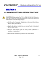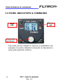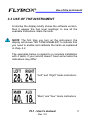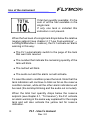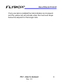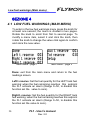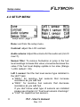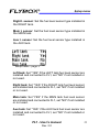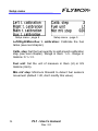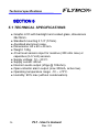
1
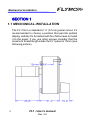
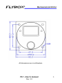
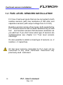
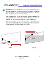
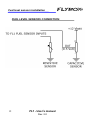
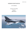
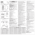
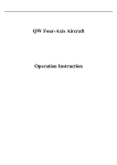
FLYBOX
®
Flybox
®
Fuel Level
FL1
Revision#2.0, 28/11/2014
FL1
User’s manual
For-firmware
version 1.2
Rev. 2.0
Page intentionally left blank
SECTIONS
MECHANICAL INSTALLATION
ELECTRICAL INSTALLATION
OPERATING INSTRUCTIONS
INSTRUMENT SETTINGS
TECHNICAL SPECIFICATIONS
FLYBOX®
Introduction
Thank you for purchasing a Flybox® product. We hope
it fully satisfy you and makes your flights pleasant and
secure.
Developing FL1, our intent was to create a compact and
lightweight fuel levels indicator, easy to install and use.
SYMBOLS USED IN THE MANUAL
NOTE: Used to highlight important informations.
CAUTION: Used to warn the user and indicate a potentially
hazardous situation or improper use of the product.
WARNING: Used to indicate a dangerous situation that can
cause personal injury or death if the instruction is
disregarded.
FL1 - User’s manual
Rev. 2.0
FLYBOX
®
Important notices & warnings
NOTE: Keep this manual in the aircraft.
This document must accompany the instrument in the event
of change of ownership.
NOTE: This device is intended for installation onto non type
certified aircraft only, because it has no aviation certifications.
Refer to your local aviation authorities to check if this device
may be installed in your aircraft.
CAUTION: Read entirely this manual before installing the
instrument in your aircraft, and follow the installation and
operating instructions described here.
CAUTION: The pilot must understand the operation of this
instrument prior to flight, and must not allow anyone to use
it without knowing the operation. Don't use this instrument
in flight until you are sure of the correct operating of the same.
CAUTION: When the installation is finished you must do a
test, prior to flight, switching on all the possible source of
electric noise and checking the properly operation of this
instrument.
CAUTION: The software of this instrument can be subject to
change, update, addition or removal of functions, so also the
operating mode of the instrument can be subject to change.
Always refer to the installation and operating manual updated
with the software version used in your instrument. To
obtain updated manuals, please visit www.flyboxavionics.it.
FL1 - User’s manual
Rev. 2.0
Important notices & warnings
FLYBOX®
WARNING: Do not solely rely on the FL1 to determine the
fuel available in the tanks.
WARNING: Responsibility for installation lies entirely with the
installer. Responsibility for operations lies entirely with the
operator. Responsibility for any calibration, settings or any
other customization lies with the person performing these
operations.
IMPORTANT: If you do not agree with the notices above
do not install this instrument in your aircraft, but return
the product for a refund.
Microel s.r.l. reserves the right to change or improve its
products. Information in this document is subject to changes
without notice.
FL1 - User’s manual
Rev. 2.0
FLYBOX
®
Index
INDEX
SECTION 1 - Mechanical installation
1.1 - Mechanical installation …….……………………………..
1.2 - Fuel level sensors installation ..…...………….…………...
8
10
SECTION 2 - Electrical installation
2.1 - Electrical installation …….………..………………….…..
13
SECTION 3 - Operating instructions
3.1 - Minimum settings before first use …….….………..…..… 15
3.2 - Panel indicators & commands .…………………………… 16
3.3 - Use of the instrument .……………………………….…… 17
SECTION 4 - Instrument settings
4.1 - Low fuel warnings menu ….….….….….….…….……….
4.2 - Setup menu ..…….…………………………………….….
4.3 - Fuel level sensors calibration …….…..…….…………….
Calibration tables ………………………….…………….
4.4 - Fuel level sensors checking …………………….…………
20
22
25
30
34
SECTION 5 - Technical specifications …….………….……….
36
Warranty …….………………………..………….…………….
37
FL1 - User’s manual
Rev. 2.0
FLYBOX®
Mechanical installation
SECTION 1
1.1 MECHANICAL INSTALLATION
The FL1 fits in a standard 2 ¼” (57 mm) panel cutout; it's
recommended to choose a position that permits optimal
display visibility.It's furnished with four M4 screws to install
it to the panel, if you use other screws consider that the
maximum thread length inside the FL1 panel is 15mm (see
following picture).
8
FL1 - User’s manual
Rev. 2.0
FLYBOX
®
Mechanical installation
All dimensions are in millimeters.
FL1 - User’s manual
Rev. 2.0
9
Fuel level sensors installation
FLYBOX®
1.2 FUEL LEVEL SENSORS INSTALLATION
FL1 has 4 fuel level inputs that can be connected to both
resistive sensors (with max resistance of 300 ohm) and
capacitive sensors (with output voltage from 0~5 Volt).
Resistive sensors can be of two types, both supported by
FL1: resistive sensors that increase resistance as you add
fuel and resistive sensors that decrease resistance as
you add fuel. If you don't know what type of sensors are
installed please see chapter 4.4 “Fuel level sensors
checkings”.
It's also possible to install a mixed type of sensors (i.e. 2
resistive + 2 capacitive).
All fuel level sensors connected to FL1 must not be
connected to any other instrument. Disconnect any
previously used instrument.
10
FL1 - User’s manual
Rev. 2.0
FLYBOX
®
Fuel level sensors installation
NOTE: Make sure that the fuel level sensors are mounted
so that all the fuel in the tank can be measured. If the fuel
sensor cannot measure completely the fuel in the tank the
FL1 will display inaccurate readings.
For example (pic.1) if a fuel sensor cannot measure the
lowest part of the tank that contains 7 liters, the FL1 will
display “0” (zero) for fuel level of 7 liters and below.
Another example (pic.2) is if a tank can holds 40 liters of
fuel but at 25 liters the fuel is at the top of the sensor, the
maximum that FL1 will display is 25 liters.
Not measurable
Not measurable
PIC.1
PIC.2
FL1 - User’s manual
Rev. 2.0
11
Fuel level sensors installation
FLYBOX®
FUEL LEVEL SENSORS CONNECTION:
12
FL1 - User’s manual
Rev. 2.0
FLYBOX
®
Electrical installation
SECTION 2
2.1 ELECTRICAL INSTALLATION
On the back of the FL1 there is a 9-pole D-SUB male
connector; it is also furnished with the corresponding 9-pole
female connector, to be wired as follows:
9-pole female connector, view from wiring side.
CAUTION: Fuel level sensors must be connected only to
the FL1. It's not possible to connect other instruments to
the fuel level sensors.
FL1 - User’s manual
Rev. 2.0
13
FLYBOX®
Electrical installation
Connector pinout:
1= +12V Main supply.
2= GND Main supply.
3= Alarm out (300mA max). Connect the load (for
example a lamp indicator) between out and +12V.
4= RIGHT tank fuel level sensor input.
5= AUX tank fuel level sensor input.
6= +12V auxiliary backup battery (if present).
7= Audio out for intercom (it's recommended to use
shielded cable).
8= LEFT tank fuel level sensor input.
9= MAIN tank fuel level sensor input.
NOTE: Insert a 1A circuit breaker or fuse to the power
lead. (+12V).
Take care to properly insulate any exposed wire, to avoid
short circuit between any of the wires.
WARNING: Voltage peaks on the supply line that exceeds
the operating limits can damage the device.
14
FL1 - User’s manual
Rev. 2.0
FLYBOX
®
Minimum settings before first use
SECTION 3
3.1 MINIMUM SETTINGS BEFORE FIRST USE
CAUTION: Before using the FL1 in flight for the first time you
must set at least the following parameters (reading the operating
instructions in the following pages):
● Set the unit of measure: USgallons or liters (set this before
all the other parameters).
● Enable the tanks installed in your aircraft and let disabled
all the other tanks.
● Set the fuel sensor type for every tanks (resistive+ /
resistive- / capacitive).
● Execute the calibration procedure for all the tanks.
FL1 - User’s manual
Rev. 2.0
15
Panel indicators & commands
FLYBOX®
3.2 PANEL INDICATORS & COMMANDS
Reserve
LED
Alarm
LED
Knob with
pushbutton
The knob can be rotated or used as a pushbutton (for
example it must be rotated to increment or decrement a
value and pushed to confirm).
16
FL1 - User’s manual
Rev. 2.0
FLYBOX
®
Use of the instrument
3.3 USE OF THE INSTRUMENT
At startup the display briefly shows the software version,
then it appear the fuel level readings; to see all the
available indications rotate the knob.
NOTE: The first time you turn on the instrument, the
display will shows “NO TANK ENABLED” to indicate that
you need to enable and calibrate the tanks as explained
in chap. 4.2.
The examples below is related to a complete installation
with 4 tanks, if your aircraft doesn't have some tanks the
indications may differ:
“Left” and “Right” tanks indications
“Main” and “Aux” tanks indications
FL1 - User’s manual
Rev. 2.0
17
FLYBOX®
Use of the instrument
Total fuel quantity available: it's the
sum of all the fuel available in the
single tank.
If only one tank is installed this
indication is not present.
When the fuel level of a single tank drops below the relative
reserve setpoint (see chapter 4.1 “Low Fuel warnings” →
Left/Right/Main/Aux t. reserve), the FL1 activate an alarm
warning in this way:
● The FL1 automatically switch to the page of the tank
that went into reserve.
● The number that indicate the remaining quantity of the
tank will blink.
● The red led will blink.
● The audio out and the alarm out will activate.
To reset the alarm condition press the knob. Note that the
tank indication will continue to blink as far as the reserve
condition remain, while all the other alarm indications will
be reset (the led stop blinking and the audio out is muted).
When the total fuel quantity drops below the reserve
setpoint (see chapter 4.1, “Tot reserve”), the FL1 activate
an alarm warning in the same way explained for the single
tank and will also activate the yellow led for reserve
indication.
18
FL1 - User’s manual
Rev. 2.0
FLYBOX
®
Use of the instrument
If only one tank is installed the total indication is not present
and the yellow led will activate when the fuel level drops
below the setpoint for that single tank.
FL1 - User’s manual
Rev. 2.0
19
FLYBOX®
Low fuel warnings (Main menu)
SEZIONE 4
4.1 LOW FUEL WARNINGS (MAIN MENU)
To enter in the low fuel warnings menu press the knob for
at least one second; the menu is divided in two pages.
Rotate the knob to scroll from first to second page. To
modify a menu item, select it and click the knob, then
rotate the knob to change the value click again to confirm
and store the new value.
Main menu - page 1
Main menu - page 2
Done: exit from the main menu and return to the fuel
readings screen.
Left t. reserve: Set the fuel quantity for the LEFT tank fuel
warning: when the fuel remaining reaches this setpoint
the FL1 activate an alarm (Range 0~50, to disable this
function set the value to zero).
Right t. reserve: Set the fuel quantity for the RIGHT tank
fuel warning: when the fuel remaining reaches this setpoint
the FL1 activate an alarm (Range 0~50, to disable this
function set the value to zero).
20
FL1 - User’s manual
Rev. 2.0
FLYBOX
®
Low fuel warnings (Main menu)
Main t. reserve: Set the fuel quantity for the MAIN tank
fuel warning: when the fuel remaining reaches this setpoint
the FL1 activate an alarm (Range 0~50, to disable this
function set the value to zero).
Aux t. reserve: Set the fuel quantity for the AUX tank fuel
warning: when the fuel remaining reaches this setpoint
the FL1 activate an alarm (Range 0~50, to disable this
function set the value to zero).
Tot reserve: Set the fuel quantity for the reserve fuel
warning: when the total fuel remaining reaches this
setpoint the FL1 activate an alarm. The total quantity is
intended as the sum of all the fuel available in the single
tanks (Range 0~200, to disable this function set the value
to zero).
NOTE: In case of only one tank installed, this function is
not enabled.
Setup: enter the setup menu (see next chapter).
FL1 - User’s manual
Rev. 2.0
21
FLYBOX®
Setup menu
4.2 SETUP MENU
Setup menu - page 1
Setup menu - page 2
Done: exit from the setup menu.
Contrast: adjust the LCD contrast.
Audio volume: Adjust the volume for the audio out (min=0
max=7).
Sensor filter: To remove fluctuation or jump in the fuel
level readings increase this value; viceversa decrease the
value if the fuel level display update is too slow (Range
1~200, default = 50).
Left t. sensor: Set the fuel level sensor type installed in
the LEFT tank:
● “RES+” for resistive fuel sensors that increase
resistance as you add fuel.
● “RES-” for resistive fuel sensors that decrease
resistance as you add fuel.
If you don't know what type of sensors are installed
please see chapter 4.4 “Fuel level sensors checkings”
● “CAP” for capacitive fuel sensors.
22
FL1 - User’s manual
Rev. 2.0
FLYBOX
®
Setup menu
Right t. sensor: Set the fuel level sensor type installed in
the RIGHT tank.
Main t. sensor: Set the fuel level sensor type installed in
the MAIN tank.
Aux t. sensor: Set the fuel level sensor type installed in
the AUX tank.
Setup menu - page 3
Left tank: Set “YES” if the LEFT tank fuel level sensor are
installed and connected to FL1, set “NO” if not installed or
not used.
Right tank: Set “YES” if the RIGHT tank fuel level sensor
are installed and connected to FL1, set “NO” if not installed
or not used.
Main tank: Set “YES” if the MAIN tank fuel level sensor
are installed and connected to FL1, set “NO” if not installed
or not used.
Aux tank: Set “YES” if the AUX tank fuel level sensor are
installed and connected to FL1, set “NO” if not installed or
not used.
FL1 - User’s manual
Rev. 2.0
23
FLYBOX®
Setup menu
Setup menu - page 4
Setup menu - page 5
Left/Right/Main/Aux t. calibration: Calibrate the fuel
tanks (see next chapter).
Calib. step: Set the fuel quantity to add at each calibration
step (see next chapter). Range in liters: 1~5 - Range in
Gallons: 0.1~1.3.
Fuel unit: Set the unit of measure in liters (Lt) or US
Gallons (UsG).
Min mV step: Minimum thresold to detect fuel sensors
movement (default = 20, don't modify this value).
24
FL1 - User’s manual
Rev. 2.0
FLYBOX
®
Fuel level sensors calibration
4.3 FUEL LEVEL SENSORS CALIBRATION
Before using the FL1 it's necessary to calibrate all the
aircraft fuel tanks, following the procedure explained in this
chapter.
The calibration is divided in more calibration steps, in each
step you will fill the tanks with predetermined fuel quantity.
The calibration end when the tank is completely filled.
It's possible to choose the fuel quantity to add at each
calibration step (see “Calib. step” parameter in the setup
menu), choose a proper value considering the tank
capacity and how many calibration step you want to
execute.
For example with a 40 liters tank and “Calib. step” set to
2 it's required 40 / 2 = 20 calibration steps. The maximum
number of calibration steps is 50.
The “Calib. step” parameter is used for all the 4 tanks
calibrations, dont't modify it once you have choosed a
value.
Begin calibration: choose the tank to calibrate and select
the relative item in the setup menu (Left t. calibration/Right
t. calibration/Main t. calibration/Aux t. calibration).
FL1 - User’s manual
Rev. 2.0
25
Fuel level sensors calibration
FLYBOX®
To enter in the calibration press the knob for at least 3
seconds until the display shows this screen (in the example
that follow the unit of measure are set to liters, the
“Calib.step” is set to 5 and the tank choosed for calibration
is the LEFT):
On this screen the following indications are displayed:
● The tank currently calibrating (1).
● The calibration step that need to be executed (2).
● The electrical output ot the fuel level sensor (3).
● “DONE”: select it and press the knob to go to the next
calibration step (4).
● The fuel quantity already added to the tank at this point
of calibration (5).
● “END CAL”: select it and press the knob to end the
calibration (6).
26
FL1 - User’s manual
Rev. 2.0
FLYBOX
®
Fuel level sensors calibration
NOTE: Before executing the following procedure prepare
the aircraft with a normal angle of attack and mantain it for
all the calibration duration.
Use the tables at the bottom of this chapter to annotate
the value of each calibration steps.
● Step #1: Drain the tank such that only the fuel unusable
remain in the tank.
● Step #2: Wait until the indication (3) is stable and click
on “DONE”.
● Step #3: Add to the tank the indicated fuel quantity (it's
the same quantity choosed with the “Calib. step”
parameter), on this example it's required to add 5 liters
of fuel:
NOTE: It's important that the fuel quantity is exactly
measured, to reach the maximum accuracy in the
calibration.
FL1 - User’s manual
Rev. 2.0
27
Fuel level sensors calibration
FLYBOX®
● Step #4: Verify that the indication (3) is changed (wait
until it is stable if necessary), annotate that value on
the table and click on “DONE”.
● Next steps: repeat step #3 and step #4 until tank is
completely filled.
● When the tank is filled: click on “DONE” to confirm the
last calibration step and then click on “END CAL” to
end the calibration. If you wish to know the tank
capacity read the indication (5) before clicking on “END
CAL”.
NOTE: A common problem for many fuel level sensors is
that they can't completely measure the tank capacity, so
one or both of this conditions can occur (see also chapter
1.2 “Fuel level sensors installation”):
- As you add fuel to an empty tank it takes a certain amount
of fuel before the fuel sensor start to move from the bottom.
- As you drain fuel to a filled tank it takes a certain amount
of fuel before the fuel sensor start to move from the top.
28
FL1 - User’s manual
Rev. 2.0
FLYBOX
®
Fuel level sensors calibration
If one of this conditions occur during calibration the FL1
notice that the fuel sensor doesn't produce an electrical
change and ask the user if fuel was already added for that
calibration step:
If you are sure to have already added the fuel click on
“YES” otherwise click on “NO” to go back to previous
calibration step.
FL1 - User’s manual
Rev. 2.0
29
FLYBOX®
Calibration tables
CALIBRATION TABLE FOR LEFT TANK:
mV of value (3)
STEP #
30
STEP #
1
26
2
27
3
28
4
29
5
30
6
31
7
32
8
33
9
34
10
35
11
36
12
37
13
38
14
39
15
40
16
41
17
42
18
43
19
44
20
45
21
46
22
47
23
48
24
49
25
50
FL1 - User’s manual
Rev. 2.0
mV of value (3)
FLYBOX
®
Calibration tables
CALIBRATION TABLE FOR RIGHT TANK:
mV of value (3)
STEP #
STEP #
1
26
2
27
3
28
4
29
5
30
6
31
7
32
8
33
9
34
10
35
11
36
12
37
13
38
14
39
15
40
16
41
17
42
18
43
19
44
20
45
21
46
22
47
23
48
24
49
25
50
FL1 - User’s manual
Rev. 2.0
mV of value (3)
31
FLYBOX®
Calibration tables
CALIBRATION TABLE FOR MAIN TANK:
mV of value (3)
STEP #
32
STEP #
1
26
2
27
3
28
4
29
5
30
6
31
7
32
8
33
9
34
10
35
11
36
12
37
13
38
14
39
15
40
16
41
17
42
18
43
19
44
20
45
21
46
22
47
23
48
24
49
25
50
FL1 - User’s manual
Rev. 2.0
mV of value (3)
FLYBOX
®
Calibration tables
CALIBRATION TABLE FOR AUX TANK:
mV of value (3)
STEP #
STEP #
1
26
2
27
3
28
4
29
5
30
6
31
7
32
8
33
9
34
10
35
11
36
12
37
13
38
14
39
15
40
16
41
17
42
18
43
19
44
20
45
21
46
22
47
23
48
24
49
25
50
FL1 - User’s manual
Rev. 2.0
mV of value (3)
33
Fuel level sensors checkings
FLYBOX®
4.4 FUEL LEVEL SENSORS CHECKINGS
To setup correctly the FL1 you need to know what type of
fuel level sensors are installed in your aicraft. The resistive
sensors can be of two types:
● Sensors that increase resistance as the fuel level
increase.
● Sensors that decrease resistance as the fuel level
increase.
If you don't know what type of resistive sensors are
installed in your aircraft follow this procedure:
● Empty the tank that you want to check.
● On the FL1 enter in the calibration for that tank (from
the setup menu press the knob for 3 seconds on “Left
t. calibration”, “Right t. calibration”, “Main t. calibration”
or “Aux t. calibration”).
● From the screen that appear annotate the numerical
value indicated in picture:
34
FL1 - User’s manual
Rev. 2.0
FLYBOX
®
Fuel level sensors checkings
● Add a certain amount of fuel to the tank and check if
the numerical indication increase or decrease: if
increase then the sensors installed increase the
resistance as you add fuel (RES+), if decrease the
sensors decrease the resistance as you add fuel
(RES-).
To exit from the calibration screen turn off the FL1 or click
on “END CAL”.
Repeat the procedure for any other unknown sensors
installed.
FL1 - User’s manual
Rev. 2.0
35
Technical specifications
FLYBOX®
SECTION 5
5.1 TECHNICAL SPECIFICATIONS
● Graphic LCD with backlight and coated glass, dimensions
29x18mm.
● Standard mounting 2 1/4” (57mm).
● Anodized aluminium case.
● Dimensions: 60 x 60 x 40 mm.
● Weight: 140g.
● 4 fuel level sensors input for resistive (300 ohm max) or
capacitive (0~5 Volt) sensors.
● Supply voltage: 12 ~ 20 V=.
● Supply current: 60mA.
● Intercom audio output (2Vpp @ 10Kohm).
● Open-collector alarm output (max 300mA, active low).
● Operating temperature range: -10 ~ +70°C.
● Humidity: 90% max (without condensation).
36
FL1 - User’s manual
Rev. 2.0
FLYBOX
®
WARRANTY:
This product is warranted to be free from defects for a
period of 12 months from the user invoice date.
The warranty only cover the manufacture's defects; shall
not apply to product that has been improper installed,
misused or incorrect maintenance, repaired or altered
by non-qualified person.
Date
05/2009
09/2010
11/2014
Revision
10
11
20
Description
First release
Updated installation notes
Layout update
WARNING: All photos, data, drawings, instruments layouts, technical solutions and
data representation you find in this document or watching at FLYBOX® instruments
working and/or you can access by means of any other media, including web sites,
are sole property of MICROEL s.r.l., cannot be copied or imitate without a written
permission of MICROEL s.r.l. itself and are protected by law, even by means of
extended international copyright and/or specific patents deposited. Any infringement
of this statement and of MICROEL s.r.l. intellectual property will be prosecuted.
©2014 Microel s.r.l. – all rights reserved.
FL1 - User’s manual
Rev. 2.0
37
Page intentionally left blank
Page intentionally left blank
MICROEL s.r.l.
Via Mortara 192-194
27038 Robbio (PV) - ITALY
Tel +39-0384-670602 - Fax +39-0384-671830
www.flyboxavionics.it