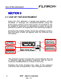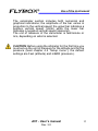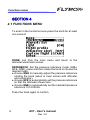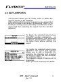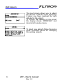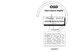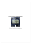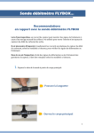
1
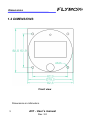
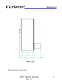
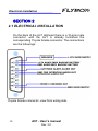
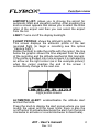
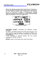
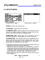
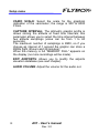
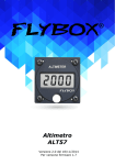
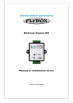
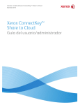
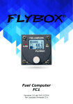
Flybox
®
Multifunction
Altimeter/Variometer
AV1
Revision#3.0, 21/11/2014
For firmware version 2.2
Page intentionally left blank
SECTIONS
MECHANICAL INSTALLATION
ELECTRICAL INSTALLATION
USE OF THE INSTRUMENT
INSTRUMENT SETTINGS
TECHNICAL SPECIFICATIONS
FLYBOX®
Introduction
Thank you for purchasing a Flybox® product. We
hope it fully satisfy you and makes your flights
pleasant and secure.
Developing AV1, our intent was to create a compact
and lightweight digital altimeter, easy to install and
quick to consult.
SYMBOLS USED IN THE MANUAL
NOTE: Used to highlight important informations.
CAUTION: Used to warn the user and indicate a potentially
hazardous situation or improper use of the product.
WARNING: Used to indicate a dangerous situation that can
cause personal injury or death if the instruction is
disregarded.
AV1 - User’s manual
Rev. 3.0
FLYBOX
®
Important notices & warnings
NOTE: Keep this manual in the aircraft.
This document must accompany the instrument in the event
of change of ownership.
NOTE: This device is intended for installation onto non type
certified aircraft only, because it has no aviation certifications.
Refer to your local aviation authorities to check if this device
may be installed in your aircraft.
CAUTION: Read entirely this manual before installing the
instrument in your aircraft, and follow the installation and
operating instructions described here.
CAUTION: Using this instrument over the maximum
allowable ranges can cause malfunction or wrong indications.
CAUTION: Microel s.r.l. reserves the right to change or
improve its products. Information in this document is subject
to changes without notice.
AV1 - User’s manual
Rev. 3.0
FLYBOX®
Index
INDEX
SECTION 1 - Mechanical installation
1.1 - Mechanical installation ……….….……………………….. 7
Pressure port connection ……..………………………….. 7
1.2 - Dimensions ……………………………………………….. 8
SECTION 2 - Electrical installation
2.1 - Electrical installation ……..………..………………….….. 10
SECTION 3 - Use of the instrument
3.1 - Use of the instrument …….…..………….….…………….
12
SEZIONE 4 - Instrument settings
4.1 - Functions menu ……..….……….………….…………….
4.2 - Setup menu ..…………………….………….…………….
4.3 - Edit airports ...……..….….….….….…….……………….
14
17
19
SEZIONE 5 - Technical specifications …..……….…………….
21
Warranty ……….…………...…………………….……………. 22
AV1 - User’s manual
Rev. 3.0
FLYBOX
®
Mechanical installation
SECTION 1
1.1 MECHANICAL INSTALLATION
1) The AV1 fits in a standard 3 1/8” (80mm) panel cutout.
2) It's recommended to choose a position that permits optimal
visibility.
PRESSURE PORT CONNECTION:
Connect the pipe fitting on the back of the instrument to a
static air pressure lines; the furnished pipe fitting is suitable
for pipe with internal diameter of 5 mm.
AV1 - User’s manual
Rev. 3.0
7
FLYBOX®
Dimensions
1.2 DIMENSIONS
Front view
Dimensions in millimeters.
8
AV1 - User’s manual
Rev. 3.0
FLYBOX
®
Dimensions
Side view
Dimensions in millimeters.
AV1 - User’s manual
Rev. 3.0
9
FLYBOX®
Electrical installation
SECTION 2
2.1 ELECTRICAL INSTALLATION
On the back of the AV1 altimeter there is a 15-pole male
connector; with the AV1 is already furnished the
corresponding 15-pole female connector. The connections
are the followings:
15-pole female connector, view from wiring side.
10
AV1 - User’s manual
Rev. 3.0
FLYBOX
®
Electrical installation
Connections detail:
1= +12V Main supply.
2= GND auxiliary backup battery (if present).
3= GND (not used).
4= GND for audio out.
5= GND (not used).
6= reserved.
7= reserved.
8= GND Main supply.
9= +12V auxiliary backup battery (if present).
10= reserved.
11= Altitude alert alarm out (300mA max). Connect the
load (for example a lamp indicator) between out and +12V.
12= Low-level audio out for intercom (it's recommended to
use shielded cable).
13= reserved.
14= reserved.
15= Mode C encoder out (open-collector) - OPTIONAL actually not used.
NOTE: Insert a 1A circuit breaker or fuse to the power
lead. (+12V).
CAUTION: Voltage peaks on the supply line that
exceeds the operating limits can damage the device.
AV1 - User’s manual
Rev. 3.0
11
FLYBOX®
Use of the instrument
SECTION 3
3.1 USE OF THE INSTRUMENT
Using the AV1 altimeter is simple and intuitive; all the
functions or settings are activated/modified using the
knob (rotary switch) on the front panel: for example it can
be rotated to increment or decrement a value or can be
pushed to confirm, as explained in the following chapters.
At startup the display briefly shows the software version,
then the main screen will appear with the altimeter and
variometer:
VARIOMETER
(GRAPHICAL
INDICATION)
CURRENT
ALTITUDE
UNIT OF
MEASURE
VARIOMETER
(NUMERICAL
INDICATION)
PRESSURE
REFERENCE
The altimeter section includes the current altitude, the unit
of measure and the pressure reference with its unit of
measure (milliBAR/hPa or inches of mercury).
Rotating the knob changes the value of the pressure
reference and consequently it also changes the altitude.
12
AV1 - User’s manual
Rev. 3.0
FLYBOX
®
Use of the instrument
The variometer section includes both numerical and
graphical indications; the amplitude of the bar varies in
proportion to the vertical speed: the upper bar indicates a
positive vertical speed (climb) while the lower bar
indicates a negative vertical speed (descend).
The unit of measure of the variometer is feet/minute or
m/s, depending on what is selected.
CAUTION: Before using the altimeter for the first time you
must set-up the unit of measure for the altitude and for the
pressure (read chapter 4.2 “Setup menu”); the default
settings are Feet (altitude) and mBAR (pressure).
AV1 - User’s manual
Rev. 3.0
13
FLYBOX®
Functions menu
SECTION 4
4.1 FUNCTIONS MENU
To enter in the functions menu press the knob for at least
one second:
DONE: exit from the main menu and return to the
altimeter/variometer screen.
REFERENCE: Set the pressure reference mode (QNH,
QFE, QNE); press and then rotate the knob to choose the
desired mode:
● choose QNH to manually adjust the pressure reference
rotating the knob (when in main screen with altimeter
and variometer).
● choose QFE to automatically set the pressure reference
so that the altimeter shows zero.
● choose QNE to automatically set the standard pressure
reference 1013.25hPa.
Press the knob again to confirm.
14
AV1 - User’s manual
Rev. 3.0
FLYBOX
®
Functions menu
AIRPORTS LIST: allows you to choose the airport for
automatic QNH and elevation setting. After pressing the
knob a screen appears that allows you to select the initial
letter of the airport and then you can select the airport
from the list.
LIGHT: Turns on/off the display backlight.
FLIGHT PROFILE: shows the altimetric profile screen.
This screen displays the altimetric profile of the last
recorded flight (to begin a recording see the option
“Capture flight”).
Rotate the knob to slide the profile with the cursor; the line
below the graphic shows the time elapsed from the start
of the recording and the altitude reached at that moment.
If the profile is divided into more screens it is indicated by
an arrow on the right corner (as in the example picture);
when the cursor reaches the end of the screen it
automatically change to the next one.
Flight profile screen.
ALTIMETER ALERT: enable/disable the altitude alert
and set the limits.
Press the knob to display the alert screen where you can
modify the upper and the lower limits; there is also the
on/off option to activate/deactivate the alert (turn the knob
clockwise to activate or counterclockwise to deactivate).
AV1 - User’s manual
Rev. 3.0
15
FLYBOX®
Functions menu
When the altitude exceeds this limit the AV1 activates a
visual indication (blinking yellow LED) and an audio tone
(on the intercom audio out). Furthermore the display
shows the indication “CLIMB” or “DESCEND” (CLIMB
when the altitude is below the lower limits and DESCEND
when the altitude is over the upper limit).
Altitude alert screen.
CAPTURE FLIGHT: start/stop the altimetric profile
recorder.
To start a recording press the knob and choose if you
want to begin a new recording (by selecting “NEW”) or if
you want to continue the last recording (by selecting
“CONTINUE”).
If the recording is already started, the only option
available is “STOP” to stop it.
SETUP: enter in the setup menu (see next chap.).
16
AV1 - User’s manual
Rev. 3.0
FLYBOX
®
Setup menu
4.2 SETUP MENU
Setup menù - page 1
Setup menù - page 2
DONE: Exit from the setup menu.
CONTRAST: adjust the LCD contrast.
ALTIMETER UNIT: Select which unit of measure will be
used for the altitude (Feet or Meters); change also the unit
for the variometer (Feet/min or Meters/sec).
PRESSURE UNIT: Select the unit of measure for the
pressure reference: hPa(mBAR) or inches of mercury.
CALIBRATION: The altimeter has been calibrated at the
factory and doesn't need further adjustments, but if you
notice that the indication is not accurate you can follow
these steps to calibrate the instrument:
● Read the current sea level barometric pressure from an
altimeter/barometer used as reference.
● Adjust the value that appears in “Calibration” so that it
coincides with the pressure read from the reference; to
modify this value you must press and hold the knob for
5 seconds (the background changes from black to
white) and then you can rotate to adjust the value.
● Press again the knob to confirm the value and exit from
the calibration.
AV1 - User’s manual
Rev. 3.0
17
FLYBOX®
Setup menu
VARIO SCALE: Select the scale for the graphical
indication of the variometer; the range is 500 to 8000
Ft/min.
CAPTURE INTERVAL: The altimetric graphic profile is
drawn storing the altitude at fixed time intervals; this
parameter allows you to select the time interval between
two altitude samplings (value can be from 1 to 60
seconds).
The maximum number of samplings is 8900, so if you
choose an interval of 1 second the graphic can store a
8900s flight (2hours and 28 minutes).
When the memory is full “MEMORY FULL” appears on
the display (no more recordings will be made).
EDIT AIRPORTS: Allows you to modify the airports
elevation database (see next chapter).
AUDIO VOLUME: Adjust the volume for the audio out.
18
AV1 - User’s manual
Rev. 3.0
FLYBOX
®
Edit Airports
4.3 EDIT AIRPORTS
This function allows you to modify, insert or delete the
airports present in the database.
After selecting “Edit Airports” it appears a new screen that
permits to create a new airport (by selecting “NEW”) or to
modify an existing one (by selecting the initial letter of the
airport and then selecting the airport from the list that
appears).
To delete the selected airport press
“DELETE”; another confirmation
is
required and pressing “YES” will delete
the airport, pressing “NO” returns it to
the setup menu without deleting the
airport.
To modify the selected airport press
“MODIFY”; the screen that appears
allows you to add a character (by
selecting the character and pressing
the knob) or delete the last character
(by selecting “DEL”).
The maximum length of the name is 14
characters.
When you have finished press “END”.
AV1 - User’s manual
Rev. 3.0
19
FLYBOX®
Edit Airports
The next screen allows you to adjust
the altitude: rotate the knob and press
it when you have reached the right
altitude for the airport.
To confirm the updating of the airport
the display shows “MODIFIED” and
returns to the setup menu.
To insert new airports follow the same
steps described above for modifying
the existing airports.
20
AV1 - User’s manual
Rev. 3.0
FLYBOX
®
Technical specifications
SECTION 5
5.1 TECHNICAL SPECIFICATIONS
- Graphic LCD with backlight and coated glass, dimensions
58x31mm.
- Standard mounting 3 1/8” (80mm).
- Anodized aluminium case.
- Dimensions: 83 x 83 x 36 mm.
- Weight: 230g.
- Altimeter range: -1000 ~ +25000 Feet.
- Altimeter resolution: 10 feet.
- Variometer range: +/- 8000 Ft/min.
- Variometer resolution: 10 Ft/min.
- Operational temperature range: -20 ~ +70°C.
- Supply voltage: 10 ~ 30 V=.
- Supply current: 80mA.
- Audio level: 2Vpp (with 10Kohm load).
- Alarm out: open-collector, 300mA max current, active low.
AV1 - User’s manual
Rev. 3.0
21
FLYBOX®
WARRANTY:
This product is warranted to be free from defects for a
period of 12 months from the user invoice date.
The warranty only cover the manufacture's defects; shall
not apply to product that has been improper installed,
misused or incorrect maintenance, repaired or altered
by non-qualified person.
Data
12/2007
11/2014
Versioni
2.3
3.0
Descrizione
First release
Layout update
WARNING: All photos, data, drawings, instruments layouts, technical solutions and
data representation you find in this document or watching at FLYBOX® instruments
working and/or you can access by means of any other media, including web sites,
are sole property of MICROEL s.r.l., cannot be copied or imitate without a written
permission of MICROEL s.r.l. itself and are protected by law, even by means of
extended international copyright and/or specific patents deposited. Any infringement
of this statement and of MICROEL s.r.l. intellectual property will be prosecuted.
©2014 Microel s.r.l. – all rights reserved.
22
AV1 - User’s manual
Rev. 3.0
Page intentionally left blank
MICROEL s.r.l.
Via Mortara 192-194
27038 Robbio (PV) - ITALY
Tel +39-0384-670602 - Fax +39-0384-671830
www.flyboxavionics.it