1
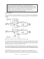
Slow-Speed Switchmotor Control Using the SMC12 Card
The use of low-current, stall motors is gaining popularity and for many C/MRI users they are totally
replacing the use of twin-coil machines. Typically, the stall-type switch motor is easier to install with less
adjustment hassle and its slow movement is more prototypical as well as easier on turnouts. You can use
two C/MRI output lines to control a stall-type switchmotor as presented in Fig. 6 within Part 2 of the
Signaling Made Easier series in the February 2004 issue of Model Railroader.
However, an attractive alternative approach is to use a single C/MRI output line. This is possible because
a turnout is a “binary device” meaning that it only has two possible “states.” These are normal and
reverse. Thus, only a single output line is required to control a turnout. Line high, open circuited,
switchmotor is in normal alignment and pulling the line low places the switchmotor in reverse alignment.
All that’s required is a simple circuit that reverses the polarity on the switchmotor’s coil as a function of
the single input line being high or low. The JLC provided SMC12 card performs this function.
Each SMC12 card can control up to 12 low-current stall-type switchmotors. It does this by employing 6
identical circuits per card where each circuit controls 2 stall-motors. Fig. 1 shows the card’s parts layout
for 3 of the 6 circuits. Each set of A and B numbered terminals connect directly to a switchmotor which is
then controlled by the correspondingly numbered control input. For example , pull input line IN1 low
causes A1 and B1 to reverse polarity. Pull IN2 low causes A2 and B2 to reverse polarity up to pulling
IN12 low reverses the polarity of A12 and B12.
Fig. 1. SMC12 Parts Layout
It should be noted that the SMC12 card replaces the original design SMC card which is no longer
available from JLC Enterprises. In principal, both cards function identically however the SMC requires
more parts and controls only 11 switchmotors. Because there are multi-hundreds of the original SMC
cards in existence, and they work great, its schematic and parts list are included in Appendix X of the
Railroader’s C/MRI Applications Handbook V3.0. The SMC12 card can be cut into sections, along the
dotted lines on the B-side of the card, for distribution around your layout as desired.
SMC12 - 1
©2004 JLC Enterprises, INC.
****Important Point****
The current output of the SMC12, and SMC, card is rated at 20mA maximum per
switchmotor. This is fine for most quality stall-type switchmotors like the Tortoise and the
original design Switchmaster. However, the replacement for the Switchmaster now being
supplied by TA Studios, and sometimes referred to as the Torquemaster, draws up to 46mA
and therefore will not work with the SMC12 or SMC cards. If you already have
Torquemasters, then you’ll need to employ the two output line method per motor with
appropriately adjusted values for the two pull-up resistors.
SMC12 Schematic
For those interested, Fig. 2 shows the schematic for the first of the six identical circuits on the SMC12
card. However if you would rather skip all the theory, simply jump ahead to the section SMC12 Card
Assembly.
Fig. 2. SMC12 schematic for the first of six identical circuits per card [1]
Power input from a filtered dc supply is connected to the +12 to 16Vdc and GND terminal screws which
in turn powers the entire card. Each numbered pair of A and B terminals are connected to a stall motor
while each control line is connected to the corresponding Control Input line. Zener diode Z1 and R5 set
the offset voltage at pins 2, 5, 9 and 12 of U1 at about +4.3Vdc.
The remainder of the schematic is identical for both switchmotors so I’ll simply point out how things
work for SM1. With the IN1 line open-circuited, the addition of D1 and R3 pull-up the voltage on pins 3
and 13 of U1 to one diode drop above the Z1 voltage, or to about +4.9Vdc. This condition causes pin 14
______________
[1] Note: The first production run of the SMC12 card (namely Rev A) has the output of U1 pin 1
connected to A1 and U1 pin 14 connected to B1. If you happen to have one of these first run cards, the
difference is easily compensated for by simply reversing the two connections going to the Switchmotor.
SMC12 - 2
©2004 JLC Enterprises, INC.
of U1 to swing to maximum positive, saturated output, the supply voltage minus about 3.5Vdc, while pin
1 approaches ground; thereby driving the switch motor to stall in one direction. Grounding the IN1
control terminal causes pins 1 and 14 of U1 to change state; thereby driving the motor to stall in the
opposite direction. The addition of R1 provides a margin of safety in preventing the burnout of Z1 in case
you accidentally connect the IN terminal up to a positive voltage source greater than 4.3V.
Since the IN1 terminal voltage switches between +4.9Vdc and ground, it is TTL compatible ; therefore
can be also fed into an input card to feed back position of manually controlled turnouts. Using a DPDT,
center-off, toggle switch as shown in Fig. 3-12 of the C/MRI User’s Manual V3.0, it’s easy to provide
both manual and automatic control of each stall motor.
The outputs of the U1 are rated at 20mA, sufficiently greater than the requirement of most low-current,
stall motors (which are typically in the 10 to 16mA range). The by far most popular brand is the Tortoise,
available from Circuitron, P.O. Box 322, Riverside, IL 60546-0322. It has a 16mA maximum stall current
when operated at 12Vdc.
SMC12 Assembly
Table 1 gives the parts list for the SMC12 and the parts layout is shown back in fig. 1. Ready-to-assemble
SMC12s are available from JLC Enterprises and complete kits as well as assembled-and-tested cards from
EASEE Interfaces. Six circuits, each controlling 2 stall motors, can be built on each card, and because all
are identical I've repeated the parts nomenclature from circuit to circuit. The parts list quantities are for
one circuit. Thus to built up a complete card you need to multiply all the quantities shown in Table 1 by 6
plus add 2 extra screws and nuts for the card’s power connections.
Table 1. SMC12 parts list (in order of recommended assembly)
Qnty.
6
6
2
3
2
2
1
1
2
1
1
Symbol
—
—
R1, R2
R3 - R5
J1 or R6
J2 or R7
D1, D2
Z1
C1
C2, C3
S1
U1
Description
4-40x ¼” pan-head machine screws (Digi-Key H142)
4-40 hex nuts (Digi-Key H216)
100O resistors [brown-black-brown]
1.0KO resistors [brown-black-red]
Make jumpers from spare ends of resistor leads or install optional
resistors in place of jumpers (see text)
1A, 100V diode (Jameco 76961 or Digi-Key 1N4002)
4.3V, 500mW zener diode (Jameco 179021 or Digi-Key 1N5229B)
1µF, 35V tantalum capacitor (Jameco 33662)
Optional (see text) .1uF, 50V monolithic capacitors (JDR .1UF-MONO)
14-pin DIP socket (Jameco 112213)
LM324N low power quad operational amplifier (Jameco 23683)
Author’s recommendations for suppliers given in parentheses above with part numbers
where applicable. Equivalent parts may be substituted. Resistors are ¼W, 5 percent
unless otherwise noted and color codes are given in brackets.
The SMC assembly steps are as follows:
• Board orientation. Make certain that all parts are installed from the top, i.e. the A-side, of the board.
Because the board looks almost identical with either side facing you, it is vitally important that during
assembly, you have the board exactly oriented as shown in Fig. 1, i.e. with the power terminals located to
your left and the dual-output switchmotor terminals along the top edge.
SMC12 - 3
©2004 JLC Enterprises, INC.
• Terminal screws. Insert 4-40 screws in each of the terminal holes from the top side, i.e. the A-Side, of
the card. Add 4-40 hex nuts on the bottom, i.e. the B-side, tighten firmly and solder the nuts to the circuit
pads.
• R1-R5. Match the color code of each resistor to the parts list. Make 90-degree bends in the leads of
each resistor so it is centered between its two holes and the leads just fit. Insert and solder while holding
the part flat against the card, then trim its leads flush with the tops of the solder tents on the back side of
the card.
• J1 or R6, J2 or R7. Note in most cases the resistors are optional and are used to increase the time it
takes for the switchmotor to throw the switch points. Increasing values of R6 and R7 make the motor run
slower. With the Tortoise, I install jumpers and find the operating speed very acceptable. Typical values
used by others range from 0Ω, a jumper, up to say 1000Ω. Note, the manufacturer of the original design
Switchmasters recommends installing a 1000Ω resistor to limit motor current. For all cases where a
resistor is not used, a jumper must be installed.
• D1, D2 [+]. Install these diodes making sure that the banded end is oriented as shown in Fig. 1.
• Z1[+]. Install this Zener diode making sure that the banded end is oriented as shown in Fig. 1.
****Point of possible interest in special cases****
It is best to use the recommended 500mW (1/2W) 4.3V Zener (generic part number
1N5229B) rather than the very originally recommend 1W 4.3V Zener (generic part number
1N4731). Using the 500mW Zener provides a logic high closer to the desired +5Vdc on the
input control line when it is open circuited. This, however, is important only for the special
case where the control input terminal on the SMC12, or SMC, card is being fed back to a
C/MRI input pin. The only time that this feedback is required is for turnouts being manually
controlled and the computer software needs to monitor the position of the turnout.
• S1[+]. Install this 14-pin IC socket making certain that the end notch lines up for correct pin-1
orientation. Push the socket tight against the card and hold it that way as you solder.
• C1[+]. Make sure that the + lead goes into the +hole as shown in the parts layout drawing and as
designated by the square pad on the board. Incorrect polarity will damage this capacitor. Solder and trim.
• C2, C3. Installing these capacitors is optional and typically only used when driving Tortoise
switchmotors for the case when not using R6 and R7. In this special case, the capacitors tend to eliminate
a slight bounce that can occur when the Tortoise reaches the end of its travel. If you don’t have this
problem, then don’t install these capacitors.
• U1[+]. Install the LM324N making sure that the notch at the end of the IC matches up with the
corresponding notch in the socket and as indicated in the parts layout diagram.
• Cleanup and inspection.
SMC12 Application Examples
Application examples for hooking up the SMC12 card are the same as for the SMC card as illustrated in
Figures 3-9, 3-11 and 3-12 in the C/MRI User’s Manual V3.0 except that the newer card handle s 12
switchmotors instead of 11 and it does so with fewer parts.
SMC12 - 4
©2004 JLC Enterprises, INC.