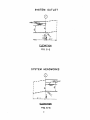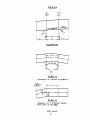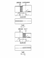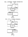
1
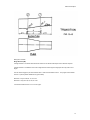
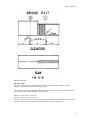
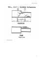
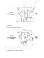
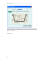
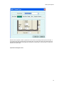
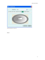
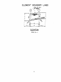
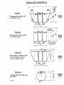
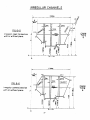
WSPG Documentation
Table of Contents
WSPG Introduction ............................................................................................................................................................ 1
Forward .......................................................................................................................................................................... 1
Introduction to WSPG..................................................................................................................................................... 1
Purpose of WSPG .......................................................................................................................................................... 1
Distributed Versions of WSPG........................................................................................................................................ 1
General Program Description............................................................................................................................................. 3
Introduction .................................................................................................................................................................... 3
Basic Theory .................................................................................................................................................................. 3
Computational Procedures ............................................................................................................................................. 3
Flow Rates ..................................................................................................................................................................... 3
Manning’s “n” ................................................................................................................................................................. 3
Starting Water Surface Elevations .................................................................................................................................. 3
Critical and Normal Depths............................................................................................................................................. 4
Velocity Head ................................................................................................................................................................. 4
Water Surface Stages .................................................................................................................................................... 4
Data Processing Description .............................................................................................................................................. 5
Data Processing System Description.............................................................................................................................. 5
Element Description........................................................................................................................................................... 7
Element Types and Construction.................................................................................................................................... 7
Boundary Lines .............................................................................................................................................................. 7
System Outlet (SO) ........................................................................................................................................................ 8
System Headworks (SH) ................................................................................................................................................ 9
Reach (R)..................................................................................................................................................................... 10
Junction Structure (JX) ................................................................................................................................................. 11
Join Structure (JO) ....................................................................................................................................................... 12
Transition Structure (TS) .............................................................................................................................................. 12
Bridge Entrance (BE) ................................................................................................................................................... 13
Bridge Exit (BX)............................................................................................................................................................ 14
Wall Entrance (WE) ...................................................................................................................................................... 15
Wall Exit (WX) .............................................................................................................................................................. 16
Channel and Conduit Section Description ........................................................................................................................ 19
Channel and Conduit Section Description .................................................................................................................... 19
Regular Channel Type Sections ................................................................................................................................... 19
Irregular Sections ......................................................................................................................................................... 20
Definitions & Restrictions for Irregular Sections ............................................................................................................ 21
Data Input Descriptions.................................................................................................................................................... 23
Data Input Descriptions ................................................................................................................................................ 23
WSPG Job Control ....................................................................................................................................................... 23
Link Element Data Dialog ............................................................................................................................................. 23
Reach .......................................................................................................................................................................... 24
Transition ..................................................................................................................................................................... 25
Node Element Data ...................................................................................................................................................... 26
System Headworks ...................................................................................................................................................... 27
System Outlet .............................................................................................................................................................. 28
Wall Entrance............................................................................................................................................................... 29
Wall Exit ....................................................................................................................................................................... 30
Bridge Entrance ........................................................................................................................................................... 31
i
Table of Contents
Bridge Exit.................................................................................................................................................................... 32
Junction ....................................................................................................................................................................... 33
Lateral Branches .......................................................................................................................................................... 34
Join .............................................................................................................................................................................. 35
Channel Selection ........................................................................................................................................................ 36
Channel Types ............................................................................................................................................................. 37
Trapezoidal Open......................................................................................................................................................... 37
Rectangular Open ........................................................................................................................................................ 38
Trapezoidal / Rectangular Closed ................................................................................................................................ 39
Pipe.............................................................................................................................................................................. 40
Irregular ....................................................................................................................................................................... 41
Irregular channel editor ................................................................................................................................................ 42
Pier Elevations Input .................................................................................................................................................... 43
Warning Messages .......................................................................................................................................................... 45
Warning messages ...................................................................................................................................................... 45
Error Messages ............................................................................................................................................................... 49
Error Messages ............................................................................................................................................................ 49
Index ............................................................................................................................................................................... 53
ii
WSPG Introduction
Forward
The use of this program by others is made and accepted with the understanding the XP Software and Los Angeles
County Public Works Department makes no warranties, express or implied, concerning its accuracy, completeness,
reliability, usability or suitability and the District shall be under no liability for any use made thereof.
Introduction to WSPG
Water Surface Pressure Gradient (WSPG) is a hydraulic analysis model that computes and plots uniform and nonuniform steady flow water surface profiles and pressure gradients in open channels or closed conduits with irregular or
regular sections. The Los Angeles County Department of Public Works (LADPW) requires use of this model for
hydraulic design.
This program was originally developed by the Design Systems and Standards Group of the Design Division and the
Data Processing Section of the Business and Fiscal Division of the Los Angeles County Flood Control District. This
program was originally written as a mainframe program called F0515P for use by the Los Angeles County Flood
Control District or by its Contractors on District projects. The program was written in FORTRAN IV, compiled using the
IBM FORTRAN H compiler executing on an IBM 370/158 using OS/VS2 MVS. The system required the use of an
input media (such as a card reader), temporary disk storage, and a printer. It was designed to run in batch mode.
In the past there have been two implementations of the WSPG: a public domain DOS program, and a menu-driven,
non-graphical Windows interface.
In April 2009, the LADPW contracted with XP Software to update the WSPG hydraulic engine and embed that engine
in a graphical user interface, namely the XP Software interface for xpswmm/xpstorm.
Purpose of WSPG
The program computes and plots uniform and non-uniform steady flow water surface profiles and pressure gradients
in open channels or closed conduits with irregular or regular sections. The flow in a system may alternate between
super critical, subcritical or pressure flow in any sequence. The program will also analyze natural river channels
although the principle use of the program is intended for determining profiles in improved flood control systems.
The collaborative effort between XP Software and the LADPW has resulted in WSPG being available in three forms:
Distributed Versions of WSPG
wspg2010:
Updated code and addition of the JOIN element, including a simple graphical interface. This version is
provided free of charge by XP Software and is available for download from www.xpsoftware.com.
xpwspg2010:
A standalone product that includes XP Software’s powerful geospatial working environment with
WSPG hydraulic calculations, profile views, export to CAD, extract network data from Digital Terrain Models, easy data
entry with xptables and much more. This product also provides access to the Modified Rational method (MODRAT)
and an automated facility to obtain hydrologic peak flows for upstream headworks nodes for simulation in the WSPG
hydraulic calculations. xpwspg2010 is available for purchase through XP Software.
xpwspg add-on module:
An add-on module for existing xpswmm and xpstorm users. The add-on module adds the
WSPG hydraulic calculations to the comprehensive XP packages. The add-on module couples the LADPW hydrologic
methods with the many existing features such as the dynamic St. Venant calculations, GIS data exchange, reports,
and water quality components available in XP Software.
1
General Program Description
Introduction
XP Software reviewed and updated the original LADPW code for WSPG. Notable modifications are herein indicated.
The XP Software re-write of WSPG primarily converted the FORTRAN to the more current programming code, C++.
The capability to handle a branching (dendritic) network was added.
Basic Theory
The computational procedure is based on solving Bernoulli’s equation for the total energy at each section and
Manning’s formula for friction loss between the sections in a reach. The open channel flow procedure utilizes the
standard step method. Confluences and bridge piers are analyzed using pressure and momentum theory.
The program uses basic mathematical and hydraulic principles to calculate all such data as cross sectional area,
wetted perimeter, normal depth, critical depth, pressure, and momentum.
The program processes the computations in three phases: Analysis of the system in the downstream direction (Phase
I), analysis of the system in the upstream direction (Phase II), and analysis of the downstream profile (from Phase I)
and the upstream profile (from Phase II) to obtain a composite profile (Phase III). The processing was designed to
continue calculating unless gross errors are encountered. Warning messages may be issued concerning tolerance
levels not being reached on an iterative approximation. These may or may not affect the overall solution to the
problem; however, processing continues. If gross errors are encountered, an error message will be issued and
processing will stop.
Computational Procedures
Input Preparation
The channel or conduit system is initially subdivided into the following elements: system outlet, reach, transition,
confluence (junction), bridge exit, bridge entrance, wall entrance (sudden contraction), wall exit (sudden expansion),
and system headworks. Each element is internally assigned a number. Additional “intermediate points” between
elements are internally set by the program. Stationing is entered by the user only at the System Outlet (S.O.); the
program uses the “length of element” to calculate the stationing.
The entire input is thoroughly scanned for required information and range values of optional information before
processing begins. If any errors are detected, processing will stop. Warnings may be issued, but the program will not
be prevented. The input data must consist of a minimum of three elements (system outlet, system headwork and
other element). The original WSPG program was limited to a maximum of 200 elements. With the XP Software
update to WSPG, that limitation was removed.
Flow Rates
The starting flow rate (Q) at the upstream terminus of a system is specified on a “Q” card. The flow rate (Q) is
increased at the desired locations by specifying lateral inflow rates on the “JX” cards. The flow rate can be reduced by
using a negative lateral “Q”.
Manning’s “n”
The program uses the Manning formula for the friction loss in all types of conduits or natural channels. The program
can only take one “n” value per element; however, the “n” value can change at subsequent elements. If a section has
a lining composed of different roughness coefficients a composite “n” based on anticipated depth of flow should be
hand computed. If an “n” value is not specified with the input data, the program uses a value of .013.
Starting Water Surface Elevations
3
WSPG Documentation
Starting water surface elevation at the downstream terminus (System Outlet S.O.) or the upstream terminus (System
Headworks S.H.) are optional input values. If not specified, the program will use critical depth elevation to begin
computations.
Critical and Normal Depths
Critical depth is computed for every section for the given Q utilizing the “Specific Energy Equation”. Normal depth is
computed in every reach element on a positive slope for the specified Q.
Velocity Head
The velocity head (HV) is computed using the mean velocity of the section. This may not be accurate in the case of a
complex section such as one with shallow flow in the horizontal overbank area where velocity distribution is not
uniform. If the program is to be used in this situation the user should be aware that some error may be introduced in
the results.
Water Surface Stages
As previously stated, the program processes in three stages. The lower stage water surface (w.s.) profile begins at
the system headworks and ends at the system outlet. The computation will proceed downstream in every consecutive
element as long as energy is available to maintain flow in the supercritical stage. When energy becomes expended at
any point in an element, the lower stage profile will be discontinued from that point to the downstream end of that
element. Then computation will resume in the next element with a critical depth control until the system outlet is
analyzed.
The upper stage w.s. profile begins at the system outlet and ends at the headworks. Computation proceeds upstream
in every element as long as the water surface at the downstream end of any two adjacent points can support the
moving mass of water to flow at the critical or subcritical depth. Otherwise, computation will be discontinued from the
downstream point to the upstream end of that element. Then computation will resume at the downstream end of the
next element with critical depth control, provided no depth less than critical depth has been computed at that point on
the lower stage profile. Then computation will proceed up stream until the system headworks is analyzed.
If the computed depth of flow in any open section exceeds the given section height the program will extend vertical
walls; a note is provided in the output file indicating the computed water surface elevation is greater than the ground
elevation.
The jump routine begins at the system outlet and ends at the headworks. It searches the lower stage and the upper
stage profiles for points of equal energy. If a jump is encountered, it will be approximately located, and data on either
the upper stage or lower stage not consistent with the greater energy theory will be deleted from every element. The
final profile will be a composite of upper stage and lower stage with hydraulic jumps in between.
4
Data Processing Description
Data Processing System Description
Prior to the XP Software update to the WSPG program, the program was written in FORTRAN IV code, compiled using
the IBM FORTRAN H compiler executing on an IBM 370/158 using OS/VS2 MVS. This system required the use of an
input media (such as a card reader), temporary disk storage, and a printer. It is designed to run in batch mode. The
XP Software update, intended for use on personal computers, used C++ code, includes a graphical user interface and
added the Join element, allowing branching (dendritic) networks to be included in a single model.
Data required to build a stream network model is similar to the DOS version of WSPG. Required data is now input
through a series of dialogs.
The entire input is thoroughly scanned for required information and range values of optional information before
processing begins. If any errors are detected, processing will stop. Warnings may be issued, but they will not prevent
processing.
Processing consists of three phases: Analysis of the system in the downstream direction (Phase I), analysis of the
system in the upstream direction (Phase II), and analysis of the downstream profile (from Phase I) and the upstream
profile (from Phase II) to obtain a composite profile (Phase III). The processing was designed to continue calculating
unless gross errors are encountered. Warning messages may be issued concerning tolerance levels not being
reached on an iterative approximation. These may or may not affect the overall solution to the problem, however,
processing continues. If gross errors are encountered, an error message will be issued and processing will stop.
Output of the system consists of an output file that can be viewed from within the program or externally using a text
editor.
5
Element Description
Element Types and Construction
The channel, conduit or natural river system to be analyzed is subdivided into elements. The XP Software version of
WSPG represents a change in the order and manner in which a model is constructed. The geographical interface
maintains geographical orientation (x,y) of elements. To maintain flow direction, the drainage network is digitized from
upstream to downstream.
The element types are:
Boundary Lines
System Outlet
System Headworks
Reach
Junction Structure
Join Structure
Transition Structure
Bridge Entrance
Bridge Exit
Wall Entrance
Wall Exit
Boundary Lines
All elements are bounded on the upstream end by Section 1 and the downstream end by Section 2 except System
Outlet (SO) and System Headworks (SH) which only have Section 1. The user inputs data such as base width,
conduit height, etc. for Section 1 of every element. The data for Section 2 for every element is taken by the program
from the upstream Section 1 of the adjacent downstream element. Elements may have considerable length between
Section 1 and Section 2 as in a reach element or may have a zero length as in a bridge entrance element.
L = length of element
X= number of the element under consideration
X+1= adjacent upstream element
X-1= adjacent downstream element
7
WSPG Documentation
System Outlet (SO)
The system outlet is the downstream terminus of a channel. X is equal to one. X+1 can be any element except a
System Headworks (SH).
8
Element Description
Dialog Box: System Outlet
System Headworks (SH)
The system headworks is the upstream terminus of a channel. Element X-1 can be any element except a system
outlet.
9
WSPG Documentation
Dialog Box: System Headworks
Reach (R)
The reach element is a length of channel, drain or natural river with a constant invert slope, Q, cross section and
Manning’s n. A reach may have a straight or curving horizontal alignment, however, a curved reach must coincide
with the beginning and end of the curve. The same applies to an angle point in the horizontal alignment; a reach must
end or begin at the angle point.
Channel types may be either opened or closed, regular or irregular. In open channels (regular rectangular or
trapezoidal sections) the super elevation of the water surface is computed and printed for each point in the curve. In
pressure flow, bend losses, angle point losses, and manhole losses are computed and add to the friction loss for the
reach. Element X+1 can be any element except a system outlet. Element X-1 can be any element except a system
headworks.
10
Element Description
Dialog Box: Reach
Junction Structure (JX)
The junction structure element is used where there is lateral inflow into the system. Two different laterals can be
handled by this element. Element X-1 can be any other element except a System Headworks (SH). Element X+1 can
be any other element except a System Outlet (SO).
11
WSPG Documentation
Dialog Box: Junction
Join Structure (JO)
The join structure element is used where there is lateral inflow into the system. Element X-1 can be any other element
except a System Headworks (SH). Element X+1 can be any other element except a System Outlet (SO).
Dialog Box: Join
Transition Structure (TS)
A transition structure is a gradual expansion or contraction from Section 1 to Section 2. The length L may be any
positive number. Element X+1 may be any element except a system outlet (SO). Element X-1 may be any element
except a system headworks (SH).
12
Element Description
Dialog Box: Transition
Bridge Entrance (BE)
A bridge entrance is an element used where flow enters from an element without piers into an element with piers.
A bridge entrance is considered to have a zero length element even though the bridge pier nose may have a minor
length.
The user should supply the pier area reduction factor. Value must be between 0 and 1. The program uses a default
value of 1.0 (See Hydraulic Handbooks for typical values).
Element X-1 may be a SO, R, JX, JO or TS.
Element X+1 may be an R, JX, JO, TS or SH.
It is noted that neither Section 1 nor 2 can be a pipe.
13
WSPG Documentation
Dialog Box: Bridge Entrance
Bridge Exit (BX)
The bridge exit is also considered to have a zero length element.
A bridge exit is an element used where flow exits from an element with piers into an element without piers.
Element X-1 may be a SO, R, JX, JO or TS.
Element X+1 may be a SH, R, JX, JO or TS.
It is noted that neither Section 1 nor 2 can be a pipe.
14
Element Description
Dialog Box: Bridge Exit
Wall Entrance (WE)
This element is used when there is a sudden change in the conduit section such as a headwall or an abrupt
contraction. This element is considered to have a zero length.
The user should supply the loss coefficient kc expressed in terms of the velocity head. The program uses a default
value of 0.5 for kc. (See Hydraulic Handbooks for typical values.)
Element X-1 may be a SO, R, JX, JO or TS.
Element X+1 may be a SH, R, JX, JO or TX.
The section for element X+1 cannot have piers, however, it can be an open channel or closed conduit. The section for
element X-1 can also be an open channel or closed conduit and it can be with or without piers.
15
WSPG Documentation
Dialog Box: Wall Entrance
Wall Exit (WX)
This element is used when there is a sudden expansion from a smaller to a larger channel or conduit section. This
element is considered to have a zero length.
Element X-1 may be a SO, R, JX, JO or TS.
Element X+1 may be a SH, R, JX, JO or TS.
The section for element X+1 may be an open channel or closed conduit with or without piers. The section for element
X-1 may be an open channel or closed conduit, however, it cannot have piers.
16
Element Description
Dialog Box: Wall Exit
17
Channel and Conduit Section Description
Channel and Conduit Section Description
Channels and conduits sections are classified as regular or irregular sections. The regular sections (Channel Types
#1 - #4) are trapezoidal, rectangular channels, box conduits or pipes. The irregular sections (Channel Types #5 and
#6) can be natural river sections or irregular shaped improved sections with or without a cover. Piers or center walls
can be included in any section except a pipe section.
Regular Channel Type Sections
The program utilizes the following regular sections:
Chan. Type #1: Trapezoidal open top with or without piers.
Dialog Box: Trapezoidal Open
Chan. Type #2: Rectangular open top with or without piers.
Dialog Box: Rectangular Open
Chan. Type #3: Box, covered trapezoidal or covered rectangular with or
piers.
without
19
WSPG Documentation
Dialog Box: Trapezoidal / Rectangular Closed
Chan. Type #4: Circular “pipe” one cell only.
Dialog Box: Pipe
Note: in multiple cell sections the cells may have variable width but must be of equal height and on the same invert
elevation. The top elevations of all piers in regular or irregular channels are assumed equal.
Irregular Sections
The program utilizes the following irregular cross sections:
Chan. Type #5: Irregular open top with or without piers.
20
Channel and Conduit Section Description
Dialog Box: Irregular
Chan. Type #6: Irregular covered with or without piers.
Dialog Box: Irregular
Definitions & Restrictions for Irregular Sections
An irregular cross section (facing upstream) is defined by x and y coordinates of points I (x,y) given in a counter
clockwise direction, from point i=1 to point i=n (minimum 3 points).
21
WSPG Documentation
Point i = 1 (x,y) is where
x (1) = x min and if x(2) is also x minimum then
y (1) is greater than y (2)
Limitations
Flow Line
Section Shape
Piers
Location of X and Y axis:
22
Data Input Descriptions
Data Input Descriptions
The user creates link-type elements, reaches, transitions, junctions and joins. Once the link is created, starting at the
upstream end of the stream, nodes are automatically inserted at each end of a link. These nodes are set to default to
dummy nodes. A dummy node has no effect on the computations. The user can then assign a node-type to these
nodes or leave as a dummy node. Each node-type element has one incoming link and one outgoing link, with
exception of the System Outlet, System Headwork and a Join. All units are US Customary.
WSPG Job Control
Title allows 3 lines of file description and title information.
The Results radio button indicates the output data presented in the output file created by solving the model.
Reporting of intermediate points in the output file can be toggled on or off.
Link Element Data Dialog
23
WSPG Documentation
The Element Data dialog allows selection of element type from a pull down list and allows the user to input data
associated with that element. Data input requirements vary based on the element selected. For reference, a quick
view of the results for the selected element is displayed in the Element Data dialog, after the WSPG model has been
solved.
The arrows progress the selection either upstream or downstream in the stream network.
Station data can only be input at the System Outlet. The program automatically calculates stations for the remainder
of the system based on the length of each subsequent element.
Element data represent the upstream end of the element. Node Invert Elevation is the elevation of the element at the
upstream end of the element. Node Ground Elevation is the elevation at which the element is assumed to no longer
contain the flow.
Channel Group is used to select the channel type (types 1-6).
Reach
24
Data Input Descriptions
The Reach element is a length of channel, drain, or natural river with a constant invert slope, flow rate, cross section
and Manning’s n-value. Element data for each Reach must be entered in the Element Data dialog. Link length must
be entered in feet. Manning’s “n” values must be entered. The program default is n=0.013.
Angle Point for closed channels is entered in degrees. If an angle point is used it is assumed to occur at the upstream
end of the reach element. The maximum recommended angle point is 15 degrees.
Angle of Curvature for closed channels is entered in degrees. If an angle of curvature is input to represent a curve in
the horizontal alignment of the reach, it is assumed for the entire length of the reach, from start to end.
Radius of Curvature for open channels is entered in feet and has similar restrictions as the Angle of Curvature.
Direction of curvature based on looking upstream in the system, positive (+) angles turn right and negative (-) angles
turn left.
Number of manholes is used for the manhole loss calculations.
Transition
25
WSPG Documentation
A transition is a link element for which the channel type is changing from the upstream to the downstream end. The
upstream section is input, the downstream section is retrieved from the downstream element.
Node Element Data
26
Data Input Descriptions
The Node Element data is used to specify the type of node from a pull down list and allows the user to input data
associated with that node. Data input requirements vary based on the node selected. For reference, a quick view of
the results for the selected element is displayed in the Element Data dialog, after the WSPG model has been solved.
The arrows progress the selection either upstream or downstream in the stream network.
Station data can only be input at the System Outlet node. The program will automatically calculate stations for the
remainder of the system based on the length of each subsequent element.
System Headworks
27
WSPG Documentation
The System Headworks is always at the uppermost upstream element of a stream or branch network. The headwork
represents the stream’s inflow boundary condition. The flow rate is input as cubic feet per second (cfs). System
headwork water surface elevation is in feet. The previous element’s elevation and channel type must be used.
System Outlet
28
Data Input Descriptions
The System Outlet (SO) node represents the terminus of the stream network. Each WSPG model has exactly one
outlet which is the most downstream element. There can be no further downstream elements. The outlet constitutes
the outflow boundary condition. The Station is entered on the SO element data dialog. System Outlet Water Surface
Elevation is in feet.
Wall Entrance
29
WSPG Documentation
A Wall Entrance is used to model a sudden channel contraction. The channel upstream of the wall entrance cannot
have piers. The entrance loss coefficient, Kc, value must be entered by the user, the default value is 0.5
Wall Exit
30
Data Input Descriptions
A wall exit is used to model a sudden channel expansion. The channel downstream the wall exit cannot have piers.
Bridge Entrance
31
WSPG Documentation
A Bridge Entrance element is used to transition from a section without piers to a section with piers. The Bridge
Entrance Reduction Factor is a reduction factor for the area of the pier. The default reduction factor is 1.0.
Bridge Exit
32
Data Input Descriptions
The Bridge Exit element is used when a channel transitions from a section with piers into a section without piers.
Junction
33
WSPG Documentation
A Junction element is used to introduce a lateral flow, a side flow entering either a channel or pipe. The lateral invert
elevation cannot be less than the downstream invert elevation. The junction cannot be bound by either a System
Headworks or a System Outlet.
The lateral branch data must be input as well.
Lateral Branches
34
Data Input Descriptions
The Junction and Join elements require that a Lateral Branch be defined. The Confluence Angle (degrees) is used to
calculate entrance losses. The incoming flow rate must be input (cfs). The invert elevation of the lateral branch
cannot be less than the downstream invert.
Confluence angle must be between 0 and 90 degrees, either positive (+) or negative (-).
Lateral inflow may be negative.
Join
35
WSPG Documentation
The Join Element is an extension of the Junction Element. The Join introduces a branch of the main stream. Rather
than simply adding in flows from a branch, the system can be included in a single model. The branch system is
defined similar to the main stream, with the exception that the downstream most element is a Join, rather than a
System Outlet. The branch network must have at least one Reach and a System Headworks.
Joins can be adjacent to more than two link elements. For each Join, the mainstream line must be defined.
The program computes the main streamline first and then the branch. The program uses the water depth in the main
streamline (from the composite profile) as an initial water surface elevation in branch network.
Channel Selection
36
Data Input Descriptions
The Channel Select dialog is used to select channel types to add to the network. The channel name is entered at the
bottom, the Add button moves the channel name to the above list. The Edit button opens the WSPG Channel Type
editor. Channels in the list may be used more than once or not used at all. The Select button returns the program to
the Element Data dialog, where the channel name is displayed as the Channel Group.
Channel Types
WSPG channel types are defined as Types 1-6. The channel input provides the basic geometry upon which the
hydraulic calculations are based. Refer to the April 1979 WSPG User Manual for more information.
Trapezoidal Open
Rectangular Open
Trapezoidal / Rectangular Closed
Pipe
Irregular
Trapezoidal Open
37
WSPG Documentation
Number of Piers is optional; however, if greater than 0, then a value for the Average width of piers must be input. If
the computed water depth is greater than the input Height value, the program will assume vertical walls extend from
the ends of the cross section, indicating depth has exceeded the channel height. If piers are present, it is assumed
that piers have infinite height.
Rectangular Open
38
Data Input Descriptions
Number of Piers is optional; however, if greater than 0, then a value for the Average width of piers must be input. If
the computed water depth is greater than the input Height value, the program will assume vertical walls extend from
the ends of the cross section, indicating depth has exceeded the channel height. If piers are present, it is assumed
that piers have infinite height.
Trapezoidal / Rectangular Closed
39
WSPG Documentation
Number of Piers is optional; however, if greater than 0, then a value for the Average width of piers must be input. If
the computed water depth is greater than the input Height value, the program will assume vertical walls extend from
the ends of the cross section, indicating depth has exceeded the channel height. If piers are present, it is assumed
that piers have infinite height.
Pipe
40
Data Input Descriptions
Circular pipe diameter is input in feet.
Irregular
41
WSPG Documentation
Irregular channel opens the Irregular Channel editor.
Restrictions were introduced on the point sets that characterize the cross section of an irregular channel. For an open
irregular channel (type 5) the cross section has to be built by a non-strictly monotonously decreasing segment followed
by a non-strictly monotonously increasing segment. This means that if following the cross section counter-clockwise,
the x-coordinates have to come in a non-decreasing order and the y-coordinates are separable into a first sequence of
non-increasing values and a second sequence of non-decreasing values.
Like in the original code, if the y-coordinates of the first and last point are not identical, the redundant part of the cross
section will be truncated.
For an irregular closed channel (type 6) a point set that fulfills the requirements has to be built by four subsequent
sequences with
1.
non-decreasing x-coordinates and non-increasing y-coordinates
2.
non-decreasing x-coordinates and non-decreasing y-coordinates
3.
non-increasing x-coordinates and non-decreasing y-coordinates
4.
non-increasing x-coordinates and non-increasing y-coordinates.
Irregular channel editor
42
Data Input Descriptions
See the full XP help file for a complete description of the irregular channel editor.
Pier Elevations Input
The reference (x,y) axis for piers must be the same as those used for the cross section. The “y” values are given from
left to right.
43
WSPG Documentation
44
Warning Messages
Warning messages
WARNING 01: Insufficient lateral characterization for junction/join [x].
WARNING 02: Maximum number of laterals for junction/join [x] reached. Rest of data will be discarded.
WARNING 03: No branches given. Join [x] will be treated as a transition.
WARNING 04: Not all elements are connected to the outlet! Computation will only be performed on objects connected
to the outlet.
WARNING 05: Too many parameters given for channel section [x]. Excessive parameters will be ignored.
WARNING 06: Upstream channel and downstream channel are the same for transition [x]. Use a reach instead?
WARNING 07: Node [x] has negative invert elevation.
WARNING 08: Number of manholes given for non-closed link [x].
WARNING 09: Pier factor for bridge entrance [x] not in valid range. Pier factor set to 1.0.
WARNING 10: Wall factor for wall entrance [x] not in valid range. Wall factor set to 0.5.
WARNING 11: Element [x] is not connected to the system outlet.
WARNING 12: Link [x] is not connected to the system outlet.
WARNING 13: Pier factor for bridge entrance [x] is below 0.667.
WARNING 14: Wall factor for wall entrance [x] is not between 0.2 and 0.9.
WARNING 15: Invert elevation of element [x] is not larger than invert elevation of the direct downstream element.
WARNING 16: One of the elevations of junction's [x] laterals is set to the invert elevation of the junction.
WARNING 17: One of the confluence angles of junction's [x] lateral is set to 90 degree.
WARNING 18: Length of junction [x] exceeds 100 feet. This is not recommended.
WARNING 19: Right slope in trapezoidal data of channel [x] set to 1.0.
WARNING 20: Left slope in trapezoidal data of channel [x] set to 1.0.
WARNING 21: A pier elevation in channel [x] is set to 0.0 because it exceeded the channel height.
WARNING 22: Element keyword [x] detected when reading a branch name.
45
WSPG Documentation
WARNING 23: For junction/join [x] fewer branches have been defined than stated by the branch number. Only the
defined branches will be processed.
WARNING 24: For junction [x] there are equally named branches.
WARNING 25: Link type element [x] has different invert elevation than its upstream node.
WARNING 26: (Not used)
WARNING 27: (Not used)
WARNING 28: (Not used)
WARNING 29: Normal depth for reach [x] could not be computed accurately. Value used in processing may be
inaccurate.
WARNING 30: Internal error. Trying to compute friction slope for element [x] with a negative wetted area or perimeter.
Set friction slope to 0.0.
WARNING 31: (Not used)
WARNING 32: Warning! Known depth equaled normal depth in Bernoulli computation for reach [x].
WARNING 33: Upper and lower limits in Bernoulli computation are the same.
WARNING 34: The target value in the Bernoulli computation is not between the bounds.
WARNING 35: (Not used)
WARNING 36: D/S processing stopped in junction [x] because critical momentum is greater than maximum
momentum.
WARNING 36: (Not used)
WARNING 37: (Not used)
WARNING 38: U/S processing stopped in junction [x] because the downstream momentum is less than maximum
momentum.
WARNING 39: Internal error during U/S processing of transition [x]. Pressure detected but computed depth is less
than maximum flow depth. Processing proceeds with less than pressure flow depth.
WARNING 40: (Not used)
WARNING 41: Steep reach in U/S processing detected in which water depth would drop below critical depth. U/S
processing stopped.
WARNING 42: (Not used)
WARNING 43: (Not used)
46
Warning Messages
WARNING 44: Jump location in reach [x] cannot be computed.
WARNING 45: One of the elevations of junction's [x] laterals is less than the U/S elevation.
WARNING 46: Channel of junction [x] defined by an irregular point set.
WARNING 47: Junction [x] has a different channel than its direct downstream element.
WARNING 48: Manning's n for pipe flow of element [x] not in recommended range 0.010 - 0.015.
WARNING 49: Manning's n for open flow of element [x] not in recommended range 0.01 - 0.06.
WARNING 50: Upstream processing: Water depth exceeds maximum open channel width for element [x]. Vertical
walls used for processing.
WARNING 51: Unknown keyword [x] encountered in [REPORT] section. Program will run with default option.
WARNING 52: Point given for regular channel [x]. Point will be discarded and program runs with regular channel data.
WARNING 53: Headwork [x] has a higher elevation than its direct downstream node.
47
Error Messages
Error Messages
Error messages 10, 24, 50 and 53 are currently not used
ERROR 1: Memory allocation error in WSPG engine.
ERROR 2: Given channel for object [x] does not exist.
ERROR 3: Element [x] seems to end a streamline but is not a headwork.
ERROR 4: Node [x] is a headwork and has an upstream node.
ERROR 5: Node [x] is the system outlet and has a downstream node.
ERROR 6: Second system outlet [x] given. (Only one system outlet allowed.)
ERROR 7: Object [x] has more than one downstream element.
ERROR 8: Trying to connect the same element [x] to a join twice.
ERROR 9: Object [x] has more than one upstream element.
ERROR 10: Please use ascending order 1,2,3,... for channel numbers. This identifier is invalid: [x].
ERROR 11: Piers defined for channel [x] but average pier width data is missing.
ERROR 12: Point set [x] requested in channel section not found.
ERROR 13: Invalid number of piers (<0 or >10) for channel section [x].
ERROR 14: Not enough pier elevations given for channel [x].
ERROR 15: Channel cross section is changing at node [x]. Must replace node by a WALL-/ or BRIDGE-type node.
ERROR 16: Upstream and downstream channels change for reach [x]. Replace by a transition?"
ERROR 17: Headwork [x] has a higher elevation than its direct downstream node.
ERROR 18: Flow defined at headwork [x] is non-positive.
ERROR 19: Channel type for channel [x] is irregular! Types have to be between 1 and 6.
ERROR 20: Link [x] has non-positive length.
ERROR 21: Invalid curvature for closed channel [x]. Absolute value of curvature must be between 0 and 180 degrees.
ERROR 22: Invalid angle point for closed channel [x]. Angle point must be between 0 and 15 degrees.
49
WSPG Documentation
ERROR 23: Manhole number of channel [x] must be between 1 and 10.
ERROR 24: Invalid value for Manning's n for channel [x].
ERROR 25: Bridge element [x] cannot have a pipe as its downstream or upstream element. Either replace bridge
element or channel definition.
ERROR 26: Channel types at bridge element [x] do not change.
ERROR 27: Channel cross sections of bridge elements [x] downstream and upstream channel do not match.
ERROR 28: Channel types at wall element [x] do not change.
ERROR 29: Upstream channel of wall entrance [x] contains piers. Use a bridge exit instead?
ERROR 30: Downstream channel of wall exit [x] contains piers. Use a bridge entrance instead?
ERROR 31: Junction [x] has a channel of irregular type.
ERROR 32: Point set for channel [x] exceeds maximum allowed number of 99.
ERROR 33: One or more errors were detected while reading the data file. Please correct the above errors first.
ERROR 34: Too many characters in input line.
ERROR 35: Input data incomplete. Too few items.
ERROR 36: Branch [x] is defined twice.
ERROR 37: Invalid keyword [x] in the data file.
ERROR 38: Duplicate ID name [x].
ERROR 39: Undefined object [x].
ERROR 40: Invalid number [x].
ERROR 41: Channel height of channel [x] is not positive.
ERROR 42: Channel width of channel [x] is not positive.
ERROR 43: Total pier width for channel [x] exceeds the channel width.
ERROR 44: Pier width for channel [x] must be a positive number.
ERROR 45: Irregular point set of channel [x] has less than 3 points.
ERROR 46: Irregular point set of channel [x] does not fulfill monotonous sequence requirements.
50
Error Messages
ERROR 47: Downstream element of element [x] is of invalid type. Element types do not match.
ERROR 48: Upstream element of element [x] is of invalid type. Element types do not match.
ERROR 49: Cannot find element [x]. Has the element been defined?
ERROR 50: Files share same names.
ERROR 51: Cannot open input file.
ERROR 52: Cannot open output file.
ERROR 53: Cannot open binary results file.
ERROR 54: There are more branches defined for junction/join [x] than stated by the branch number.
ERROR 55: [x] is larger than the maximum allowed branch number.
ERROR 56: Branch name [x] has already been used for the join.
ERROR 57: Branch name [x] given in the [NETWORK] section hasn't been assigned to any join.
ERROR 58: The [NETWORK] section is supposed to start with an outlet. It starts with element [x] which is not an
outlet.
ERROR 59: The beginning of a branch is expected to start with a join. Element [x] found which is not a join.
ERROR 60: Flow specified at headwork [x] has not the same value than the flow specified at the corresponding join.
ERROR 61: Missing branch for join [x]. More laterals have been defined than branches were given.
ERROR 62: Outlet already used.
ERROR 63: No headwork expected [x], stream too short branch.
ERROR 64: The branch name [x] hasn't been assigned to the join.
ERROR 65: Error in computation! Negative wetted area computed for channel [x]. Abnormal stop of processing.
ERROR 66: Internal error when computing wetted area. Abnormal stop of processing.
ERROR 67: Error in computation! Negative wetted perimeter computed. Abnormal stop of processing.
ERROR 68: Error in computation! Negative depth computed. Abnormal stop of processing.
ERROR 69: Error in processing: No wall obstruction in wall entrance [x] detected. Abnormal stop of computation.
ERROR 70: Abnormal stop during U/S processing of element [x]. Water elevation too high for maximum channel
depth."
51
WSPG Documentation
ERROR 71: Couldn't solve quadratic equation when determining end of pressure flow in reach [x] during U/S
processing.
ERROR 72: Abnormal stop during U/S processing of reach: water depth is too high for reach with non-positive slope.
ERROR 73: There was neither a D/S processing nor an U/S processing for element [x].
ERROR 74: Reading the old WSPG data file format failed.
ERROR 75: Junction/Join [x] has a lateral with invalid internal channel number.
ERROR 76: Junction/Join [x] has a lateral whose invert elevation is less than the D/S invert elevation.
ERROR 77: There were errors when validating the input data. Please correct the above errors first.
ERROR 78: Error when validating [x]. A valid channel description for the direct downstream element could not be
found.
ERROR 79: Cannot open error log file.
ERROR 80: No system outlet detected.
ERROR 81: Channel [x] not found.
ERROR 82: Channel ID [x] defined multiple times.
ERROR 83: Error in computation! Pier width exceeds top flow width for channel [x]. (Wetted area set to 0.0.)
52
Index
B
Link Element Data Dialog
Basic Theory
3
Boundary Lines
7
Bridge Entrance
31
Bridge Entrance BE
13
Bridge Exit
32
Bridge Exit BX
14
C
Channel and Conduit Section Description
19
Channel Selection
36
Channel Types
37
23
M
Manning’s
3
N
Node Element Data
26
P
Pier Elevations Input
43
Pipe
40
Purpose of WSPG
1
R
Reach
24
Computational Procedures
3
Reach R
10
Critical and Normal Depths
4
Rectangular Open
38
Regular Channel Type Sections
19
D
Data Input Descriptions
Data Processing System Description
Definitions & Restrictions for Irregular Sections
Distributed Versions of WSPG
23
5
21
1
E
Element Types and Construction
Error Messages
S
Starting Water Surface Elevations
System Headworks
49
F
27
System Headworks SH
System Outlet
7
3
9
28
System Outlet SO
8
T
Transition
25
Flow Rates
3
Transition Structure TS
12
Forward
1
Trapezoidal / Rectangular Closed
39
Trapezoidal Open
37
I
Introduction
Introduction to WSPG
3
1
V
Velocity Head
4
W
Irregular
41
Irregular channel editor
42
Wall Entrance
29
Irregular Sections
20
Wall Entrance WE
15
J
Join
35
Wall Exit
30
Wall Exit WX
16
45
Join Structure JO
12
Warning messages
Junction
33
Water Surface Stages
Junction Structure JX
11
WSPG Job Control
4
23
L
Lateral Branches
34
53