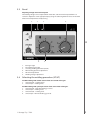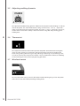
1
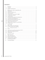
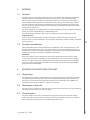
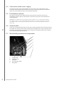
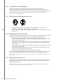
Kempact
MIG 2530
Operating manual
Käyttöohje
EN
FI
Bruksanvisning
SV
Bruksanvisning
NO
Brugsanvisning
DA
Gebrauchsanweisung
DE
Gebruiksaanwijzing
NL
Manuel d’utilisation
FR
Manual de instrucciones
ES
Instrukcja obsługi
PL
Инструкции по эксплуатации
RU
操作手册
ZH
Manual de utilização
PT
Manuale d’uso
IT
EN
OPERATING MANUAL
English
© Kemppi Oy / 1204
1
CONTENTS
1.
Preface............................................... . . . . . . . . . . . . . . . . . . . . . . . . . . . . . . . . . . . . . . . . . . . . . . . . . . . . . . . . . . . . . . . . . . . . . . . . . . . . . . . . . . . . . . . . 3
1.1General. ............................................... . . . . . . . . . . . . . . . . . . . . . . . . . . . . . . . . . . . . . . . . . . . . . . . . . . . . . . . . . . . . . . . . . . . . . . . . . . . . . . . . . . . . . . . . 3
1.2 Product introduction. .................... . . . . . . . . . . . . . . . . . . . . . . . . . . . . . . . . . . . . . . . . . . . . . . . . . . . . . . . . . . . . . . . . . . . . . . . . . . . . . . . . . . . . . . . . 3
2.
EN
Before you start using the unit. . . . . . . . . . . . . . . . . . . . . . . . . . . . . . . . . . . . . . . . . . . . . . . . . . . . . . . . . . . . . . . . . . . . . . . . . . . . . . . . 3
2.1Unpacking. ......................................... . . . . . . . . . . . . . . . . . . . . . . . . . . . . . . . . . . . . . . . . . . . . . . . . . . . . . . . . . . . . . . . . . . . . . . . . . . . . . . . . . . . . . . . . 3
2.2 Placement of the unit. ................... . . . . . . . . . . . . . . . . . . . . . . . . . . . . . . . . . . . . . . . . . . . . . . . . . . . . . . . . . . . . . . . . . . . . . . . . . . . . . . . . . . . . . . . . 3
2.3 Serial number.................................... . . . . . . . . . . . . . . . . . . . . . . . . . . . . . . . . . . . . . . . . . . . . . . . . . . . . . . . . . . . . . . . . . . . . . . . . . . . . . . . . . . . . . . . . 3
2.4 Connection to the mains supply. . . . . . . . . . . . . . . . . . . . . . . . . . . . . . . . . . . . . . . . . . . . . . . . . . . . . . . . . . . . . . . . . . . . . . . . . . . . . . . . . . . . . . . 4
2.5 Distribution network...................... . . . . . . . . . . . . . . . . . . . . . . . . . . . . . . . . . . . . . . . . . . . . . . . . . . . . . . . . . . . . . . . . . . . . . . . . . . . . . . . . . . . . . . . . 4
2.6 Ground cable..................................... . . . . . . . . . . . . . . . . . . . . . . . . . . . . . . . . . . . . . . . . . . . . . . . . . . . . . . . . . . . . . . . . . . . . . . . . . . . . . . . . . . . . . . . . 4
2.7 Wire feeding mechanism components.. . . . . . . . . . . . . . . . . . . . . . . . . . . . . . . . . . . . . . . . . . . . . . . . . . . . . . . . . . . . . . . . . . . . . . . . . . 4
2.8 Installation of welding gun.......... . . . . . . . . . . . . . . . . . . . . . . . . . . . . . . . . . . . . . . . . . . . . . . . . . . . . . . . . . . . . . . . . . . . . . . . . . . . . . . . . . . . . . . . . 6
2.9 Mounting and locking of wire reel. . . . . . . . . . . . . . . . . . . . . . . . . . . . . . . . . . . . . . . . . . . . . . . . . . . . . . . . . . . . . . . . . . . . . . . . . . . . . . . . . . . 6
2.10 Automatic wire feed to gun........ . . . . . . . . . . . . . . . . . . . . . . . . . . . . . . . . . . . . . . . . . . . . . . . . . . . . . . . . . . . . . . . . . . . . . . . . . . . . . . . . . . . . . . . . 6
2.11 Adjustment of pressure................. . . . . . . . . . . . . . . . . . . . . . . . . . . . . . . . . . . . . . . . . . . . . . . . . . . . . . . . . . . . . . . . . . . . . . . . . . . . . . . . . . . . . . . . . 6
2.12 Adjustment of tightness of reel brake.. . . . . . . . . . . . . . . . . . . . . . . . . . . . . . . . . . . . . . . . . . . . . . . . . . . . . . . . . . . . . . . . . . . . . . . . . . . . 7
2.13 Shielding gas..................................... . . . . . . . . . . . . . . . . . . . . . . . . . . . . . . . . . . . . . . . . . . . . . . . . . . . . . . . . . . . . . . . . . . . . . . . . . . . . . . . . . . . . . . . . 7
3.Operation. ....................................... . . . . . . . . . . . . . . . . . . . . . . . . . . . . . . . . . . . . . . . . . . . . . . . . . . . . . . . . . . . . . . . . . . . . . . . . . . . . . . . . . . . . . . . . 8
3.1 Main switch and signal lights..... . . . . . . . . . . . . . . . . . . . . . . . . . . . . . . . . . . . . . . . . . . . . . . . . . . . . . . . . . . . . . . . . . . . . . . . . . . . . . . . . . . . . . . . . 8
3.2 To select polarity for welding. .... . . . . . . . . . . . . . . . . . . . . . . . . . . . . . . . . . . . . . . . . . . . . . . . . . . . . . . . . . . . . . . . . . . . . . . . . . . . . . . . . . . . . . . . . 8
3.2.1 Changing the polarity. ............. . . . . . . . . . . . . . . . . . . . . . . . . . . . . . . . . . . . . . . . . . . . . . . . . . . . . . . . . . . . . . . . . . . . . . . . . . . . . . . . . . . . . . . . . 8
3.3Panel. .................................................... . . . . . . . . . . . . . . . . . . . . . . . . . . . . . . . . . . . . . . . . . . . . . . . . . . . . . . . . . . . . . . . . . . . . . . . . . . . . . . . . . . . . . . . . 9
3.4 Selecting the welding procedure (2T/4T). . . . . . . . . . . . . . . . . . . . . . . . . . . . . . . . . . . . . . . . . . . . . . . . . . . . . . . . . . . . . . . . . . . . . . 9
3.5 Adjusting welding dynamics. ..... . . . . . . . . . . . . . . . . . . . . . . . . . . . . . . . . . . . . . . . . . . . . . . . . . . . . . . . . . . . . . . . . . . . . . . . . . . . . . . . . . . . . . . 10
3.6Thermostat......................................... . . . . . . . . . . . . . . . . . . . . . . . . . . . . . . . . . . . . . . . . . . . . . . . . . . . . . . . . . . . . . . . . . . . . . . . . . . . . . . . . . . . . . . 10
3.7 Wire feed switch............................... . . . . . . . . . . . . . . . . . . . . . . . . . . . . . . . . . . . . . . . . . . . . . . . . . . . . . . . . . . . . . . . . . . . . . . . . . . . . . . . . . . . . . . 10
4.Maintenance. ................................ . . . . . . . . . . . . . . . . . . . . . . . . . . . . . . . . . . . . . . . . . . . . . . . . . . . . . . . . . . . . . . . . . . . . . . . . . . . . . . . . . . . . . . 11
4.1 Daily maintenance. ......................... . . . . . . . . . . . . . . . . . . . . . . . . . . . . . . . . . . . . . . . . . . . . . . . . . . . . . . . . . . . . . . . . . . . . . . . . . . . . . . . . . . . . . . 11
4.2 Regular maintenance..................... . . . . . . . . . . . . . . . . . . . . . . . . . . . . . . . . . . . . . . . . . . . . . . . . . . . . . . . . . . . . . . . . . . . . . . . . . . . . . . . . . . . . . . 11
4.3 Disposal of the machine............... . . . . . . . . . . . . . . . . . . . . . . . . . . . . . . . . . . . . . . . . . . . . . . . . . . . . . . . . . . . . . . . . . . . . . . . . . . . . . . . . . . . . . . 11
5.
6.
2
Ordering numbers. ................... . . . . . . . . . . . . . . . . . . . . . . . . . . . . . . . . . . . . . . . . . . . . . . . . . . . . . . . . . . . . . . . . . . . . . . . . . . . . . . . . . . . . . . 11
Technical data. ............................. . . . . . . . . . . . . . . . . . . . . . . . . . . . . . . . . . . . . . . . . . . . . . . . . . . . . . . . . . . . . . . . . . . . . . . . . . . . . . . . . . . . . . . 12
Kempact MIG 2530
1.
PREFACE
1.1 General
Congratulations on your choice of the Kempact™ series power source. Reliable and durable,
Kemppi products are affordable to maintain, and they increase your work productivity.
This user manual contains important information on the use, maintenance, and safety of
your Kemppi product. The technical specifications of the device can be found at the end of
the manual. Please read the manual carefully before using the equipment for the first time.
For your safety and that of your working environment, pay particular attention to the safety
instructions in the manual.
For more information on Kemppi products, contact Kemppi Oy, consult an authorised Kemppi
dealer, or visit the Kemppi Web site at www.kemppi.com.
The specifications presented in this manual are subject to change without prior notice.
Important notes
Items in the manual that require particular attention in order to minimise damage and
personal harm are indicated with the ’NOTE!’ notation. Read these sections carefully and follow
their instructions.
1.2 Product introduction
EN
The Kempact MIG 2530 is compact MIG inverter suitable for repair and installation use, and
for light and medium industrial use. The power source and the wire feeding mechanism are
contained in the device. The power regulation of the power source is implemented with IGBT
transistors operating at a frequency of approximately 30 kHz.
Disclaimer
While every effort has been made to ensure that the information contained in this guide
is accurate and complete, no liability can be accepted for any errors or omissions. Kemppi
reserves the right to change the specification of the product described at any time without
prior notice. Do not copy, record, reproduce or transmit the contents of this guide without
prior permission from Kemppi.
2.
BEFORE YOU START USING THE UNIT
2.1 Unpacking
The equipment is packed in durable packages, designed specially for it. Nevertheless, before
using the equipment, always make sure it was not damaged during transport. Also check
that you have received what you ordered and that there are instructions for it. NOTE! The
packaging material of the products is suitable for recycling.
2.2 Placement of the unit
Place the unit on a horizontal, solid, and clean surface. Shield it from heavy rain and scorching
sun. Make sure that cooling air circulates freely.
2.3 Serial number
The serial number of the unit is marked on the rating plate of the unit. The serial number
makes it possible to trace product manufacturing series. You might need the serial number
when placing spare parts orders or when planning maintenance.
© Kemppi Oy / 1204
3
2.4 Connection to the mains supply
The Kempact 2520 is delivered equipped with a five metre mains cable without a plug.
Installation of the plug should be carried out only by a competent electrician. For fuse and
cable sizes, see the technical data in the end of this document.
2.5 Distribution network
All regular electrical devices without special circuits generate harmonic currents into
distribution network. High rates of harmonic current may cause losses and disturbance to
some equipment.
WARNING: This equipment does not comply with IEC 61000-3-12. If it is connected to a public
low voltage system, it is the responsibility of the installer or user of the equipment to ensure, by
consultation with the distribution network operator if necessary, that the equipment may be
connected.
2.6 Ground cable
EN
Fasten the earth clamp of the return current cable carefully, preferably direct onto the piece to
be welded. The contact surface of the earth clamp should always be as large as possible. Clean
the fastening surface from paint and rust. Use at least 35 mm² cables. Thinner cross-sectional
areas cause overheating of connectors.
2.7 Wire feeding mechanism components
1.
2.
3.
4.
5.
1.
2.
3.
4.
5.
4
Clamp screw
Clamping lever
Feed rolls
Gun connector (Euro)
Wire guides
Kempact MIG 2530
DuraTorque™ 400, 4 wheel wire feed mechanism
Wire guide tubes
Ss, Al, Fe, ø 0,6 ... 1,6 mm
Mc, Fc
ø 2.5/64 mm,
W000762,
silver, plastic
ø 2.5/33 mm,
W000956,
silver, plastic
ø 2.0 mm,
W000624,
plastic
ø 1,6 ... 2,4 mm
ø 3.5/64 mm,
W001430,
silver, plastic
ø 3.5/33 mm,
W001431,
silver, plastic
ø 3.5 mm,
W001389,
plastic
Fe, Mc, Fc ø 0,6 ... 0,8 mm
ø 1.0/67 mm,
W001432,
white, steel
ø 2.0/33 mm,
W001435,
orange, steel
ø 2.0 mm,
W000624,
plastic
ø 0,9 ... 1,6 mm
ø 2.0/64 mm,
W001433,
orange, steel
ø 1,6 ... 2,4 mm
ø 4.0/63 mm,
W001434,
blue, steel
ø 3.5 mm,
W001389,
plastic
ø 4.0/33 mm,
W001436,
blue, steel
ø 3.5 mm,
W001391,
brass
EN
2.
1.
Wire feed rolls
Fe, Ss, Al,
V-groove
Fe, Fc, Mc,
knurled
Fe, Fc, Mc,
Ss, Al,
U-groove
ø mm
Colour
Drawing
Pressing
0.6
pale grey
W001045
W001046
0.8/0.9
white
W001047
W001048
1.0
red
W000675
W000676
1.2
orange
W000960
W000961
1.4
braun
W001049
W001050
1.6
yellow
W001051
W001052
2.0
grey
W001053
W001054
2.4
black
W001055
W001056
1.0
red
W001057
W001058
1.2
orange
W001059
W001060
1.4/1.6
yellow
W001061
W001062
2.0
grey
W001063
W001064
2.4
black
W001065
W001066
1.0
red
W001067
W001068
1.2
orange
W001069
W001070
1.6
yellow
W001071
W001072
© Kemppi Oy / 1204
5
2.8 Installation of welding gun
Make sure the gun wire conduit and the flow nozzle match the manufacturer’s
recommendations for the type and diameter of wire you use. Too small a conduit may
overload the wire feed device and disturb the wire feeding. Tighten the gun quick connector
to eliminate voltage losses. A loose joint will make the gun and the wire feeder warm.
NOTE! Do not use a damaged gun.
2.9 Mounting and locking of wire reel
LOCKED
EN
OPEN
• Release locking nails of wire reel hub by turning locking knob a quarter round.
• Mount the reel at its place. Note rotating direction of reel!
• Lock the reel with locking knob, locking nails of hub remain to outside position and will
lock the reel.
2.10 Automatic wire feed to gun
Automatic wire feed makes change of wire reel more rapid. In reel change the pressure of feed
rolls need not to be released and filler wire goes automatically to correct wire line.
• Make sure that groove of feed roll matches the diameter of welding wire used.
• Release the wire end from reel and cut off the bent length. Be careful that the wire does
not spill from the reel to sides!
• Straighten about 20 cm of the wire and see that the end of it has no sharp edges (file
off if necessary). A sharp edge may damage the wire guide tube and contact tip of the
welding gun.
• Draw a bit of loose wire from wire reel. Feed wire through back liner to feed rolls. Do not
release pressure of feed rolls!
• Press the gun switch and feed a bit wire until wire goes through feed rolls to gun. See
that wire is in grooves of both feed roll pairs!
• Press still the gun switch until wire has come through contact tip.
Automatic feed may sometimes fail with thin wires (Fe, Fc, Ss: 0.6...0.8 mm, Al: 0.8...1.0 mm). In
that case you might have to open feed rolls and feed wire manually through feed rolls.
NOTE! Check that the wire or wire reel does not touch the equipment body, there is a danger of
short circuit
2.11 Adjustment of pressure
Adjust the pressure of feed rolls with the control screw so that the wire is fed into the wire
guide tube evenly and allows a little braking when coming out from the contact tip without
slipping at the feed rolls.
NOTE! Excessive pressure causes flattening of the filler wire and damage to the coating. It also
causes undue wear of the feed rolls as well as friction.
6
Kempact MIG 2530
2.12 Adjustment of tightness of reel brake
A
Brake force is adjusted through hole in locking device of reel hub by screwing the control
screw (A) with screwdriver.
Adjust brake force as so big that the wire is not allowed to become too loose on the reel so
that it would spill from the reel when the rotation of the reel stops. Need for brake force is
increased with increase of wire feed speed.
Since the brake loads for its part the motor, you shouldn’t keep it unnecessarily tight.
2.13 Shielding gas
The MIG shielding gas consists of carbon dioxide, mixed gases and argon. Shielding gas
flow rate is determined by the amount of welding current. The typical flow rate of gas in the
welding of steel is 8–15 l / min.
EN
The following installation instructions are valid for most gas flow regulator types:
A
C
F
G
B
E
D
Parts of gas flow regulator
A. Gas bottle valve
B. Pressure regulation screw
C. Connecting nut
D. Hose spindle
E. Jacket nut
F. Gas bottle pressure meter
G. Gas hose pressure meter
1.
2.
3.
4.
5.
6.
7.
Step aside and open the bottle valve (A) for a while to blow out possible impurities.
Turn the press regulation screw (B) of the regulator until no spring pressure can be felt.
Close the needle valve if there is one in the regulator.
Install the regulator on bottle valve and tighten the connecting nut (C) with a wrench.
Install the hose spindle (D) and jacket nut (E) into the gas hose and tighten with a hose
clamp
Connect the hose with the regulator and the other end with the wire feed unit.
Tighten jacket nut.
Open the bottle valve slowly. The gas bottle pressure meter (F) shows bottle pressure.
© Kemppi Oy / 1204
7
NOTE! Do not use the whole contents of the bottle. Bottle should be filled when bottle pressure is
2 bar.
8. Open the needle valve if there is one in the regulator.
9. Turn the regulation screw (B) until the hose pressure meter (G) shows the required flow
(or pressure). When regulating the flow amount, the power source should be switched
on and the gun switch pressed simultanously.
NOTE! Close the bottle valve after welding is finished. If the machine will not be in use for a long
time, unscrew the pressure regulation screw. Always fasten the gas ottle tightly in vertical position,
to a wall stand or bottle cart, specially designed for it. For safety reasons, always remove the gas
bottle from the transport stand of the machine before lifting of transport of the machine by car!
3.
OPERATION
3.1 Main switch and signal lights
EN
With the switch in the ‘I’ position, the primary and control circuits of the machine become live
and the ‘ON’ signal light on the panel lights up. The welding circuit receives voltage when the
gun switch is operated or when the wire feed test switch is pressed.
Always use the main switch to turn the machine on and off with the main switch; do not use
the power plug for this purpose.
3.2 To select polarity for welding
Solid wire is usually welded in + pole and cored wire in – pole gun. Check for the
recommended polarity on the package or consult th esupplier of the product. The welding of
very thin plates (0.5 to 0.7 mm) – polarity might also work best for solid wire.
3.2.1 Changing the polarity
1.
2.
1.
2.
– pole
+ pole
NOTE! Only a service shop authorised by Kemppi may change the polarity.
8
Kempact MIG 2530
3.3 Panel
Adjusting voltage and wire feed speed
The welding voltage can be adjusted from 10 to 30 V, and the wire feed speed from 1 to
18 m/min. Adjust the values appropriately by using the table of guideline values on the door
of the wire compartment and by testing.
3.
2.
1.
6.
EN
4.
1.
2.
3.
4.
5.
6.
5.
ON signal light
Thermostat signal light
Selecting welding procedure (2T/4T)
MIG welding dynamics adjustment
Wire feed adjustment
Welding voltage adjustment
3.4 Selecting the welding procedure (2T/4T)
2T: MIG welding with double action of the start switch of the gun:
1. Switch closed – welding starts.
2. Switch open – welding ends.
4T: MIG welding with quadruple action of the start switch of the gun:
1. Switch closed – flow of shielding gas starts.
2. Switch open – welding starts.
3. Switch closed – welding ends.
4. Switch open – flow of shielding gas ends.
© Kemppi Oy / 1204
9
3.5 Adjusting welding dynamics
The adjustment of MIG welding dynamics influences the properties of the welding arc and the
amount of splatter. The recommended basic setting is ‘0’. The values -> min (-1...-9) provide a
softer arc for diminishing the amount of spatter. The values -> max (1...9) provide a coarser arc,
suitable when increased arc stability is desired and when using 100% CO₂ shielding gas for
welding steel.
EN
3.6 Thermostat
The temperature control of the machine prevents the power source from over-heating.This
means that the machine can not become damaged if loading exceeds the specified load
factor during welding. When the signal lamp indicating overheating is lit, the welding circuit
can not be activated. The lamp will turn off after a pause of about three minutes, and welding
can be started again in the usual way by pressing gun switch.
3.7 Wire feed switch
The wire feed switch will start the wire feed motor without opening the gas valve. The power
source will start up, but without providing welding power.
10
Kempact MIG 2530
4.
MAINTENANCE
4.1 Daily maintenance
NOTE! Be careful of mains voltage when handling electric cables!
Clean the wire channel of the electrode and check the contact tip regularly. Always check the
condition of the mains and welding cable before operation and replace defective cables.
NOTE! Only a competent electrician is allowed to remove or install the mains cable!
4.2 Regular maintenance
KEMPPI -service workshops sign special service contracts with customers for regular
maintenance. All parts are cleaned, checked and if necessary, repaired. Also the operation of
the welding machine is tested.
4.3 Disposal of the machine
Do not dispose of electrical equipment with normal waste!
In observance of European Directive 2002/96/EC on waste electrical and electronic
equipment, and its implementation in accordance with national law, electrical equipment
that has reached the end of its life must be collected separately and taken to an appropriate
environmentally responsible recycling facility.
The owner of the equipment is obliged to deliver a decommissioned unit to a regional
collection centre, per the instructions of local authorities or a Kemppi representative. By
applying this European Directive you will improve the environment and human health.
5.
EN
ORDERING NUMBERS
Kempact MIG 2530
GH 30 Gun holder
MMT 25
MMT 25
MMT 27
MMT 27
Earth cable 35 mm²
Transport unit ST 7
Transport unit P250
Lift hook
Wire spool pole
5 kg spool adapter
Gas hose
© Kemppi Oy / 1204
621853002
6256030
3m
6252513MMT
4.5 m
6252514MMT
3m
6252713MMT
4.5 m
6252714MMT
5m
6184311
6185290
6185268
4298180
4289880
4251270
6m
W000566
11
6.
TECHNICAL DATA
Kempact MIG 2530
Connection voltage
Rated power at max. current
Supply current
Connection cable
Fuse (delayed)
Output 40 °C
EN
Welding range
Open circuit voltage
Power factor at max. current
Efficiency at max. current
Wire feed speed
Filler wires
Shielding gas
Wire spool (max. ø)
Thermal class
External dimensions
Weight
Operating temperature range
Storage temperature range
EMC class
Degree of protection
Standards
IEC/EN 60974-1
IEC/EN 60974-5
IEC/EN 60974-10
* See paragraph 2.5.
12
Kempact MIG 2530
3~, 50/60Hz
380 – 440V ±10%
40% ED
250 A / 12 kVA
I1max
17 A
I1eff
11 A
H07RN-F
4G1.5 (5 m)
16 A
40% ED
250 A /26.5 V
60% ED
207 A / 24 V
100% ED
160 A / 22 V
10 – 30 V
30 – 45 V
0.64
87%
1 – 18 m/min
Fe, Ss
ø 0.6 – 1.0 mm
Cored wire
ø 0.9 – 1.2 mm
Al
ø 0.9 – 1.2 mm
Cusi
ø 0.8 – 1.0 mm
CO₂, Ar, Ar & CO₂ mixed gases
300 mm (15 kg)
H(180 °C) / B (130 °C)
LxWxH
580x280x440
20 kg
-20 °C ... +40 °C
-40 °C ... +60 °C
A
IP23S
KEMPPI OY
Kempinkatu 1
PL 13
FIN-15801 LAHTI
FINLAND
Tel +358 3 899 11
Telefax +358 3 899 428
[email protected]
www.kemppi.com
Kotimaan myynti:
Tel +358 3 899 11
Telefax +358 3 734 8398
[email protected]
KEMPPI SVERIGE AB
Box 717
S-194 27 UPPLANDS VÄSBY
SVERIGE
Tel +46 8 590 783 00
Telefax +46 8 590 823 94
[email protected]
KEMPPI NORGE A/S
Postboks 2151, Postterminalen
N-3103 TØNSBERG
NORGE
Tel +47 33 346000
Telefax +47 33 346010
[email protected]
KEMPPI DANMARK A/S
Literbuen 11
DK-2740 SKOVLUNDE
DANMARK
Tel +45 4494 1677
Telefax +45 4494 1536
[email protected]
KEMPPI BENELUX B.V.
Postbus 5603
NL-4801 EA BREDA
NEDERLAND
Tel +31 765717750
Telefax +31 765716345
[email protected]
KEMPPI FRANCE S.A.S.
65 Avenue de la Couronne des Prés
78681 EPONE CEDEX
FRANCE
Tel +33 1 30 90 04 40
Telefax +33 1 30 90 04 45
[email protected]
KEMPPI GmbH
Otto-Hahn-Straße 14
D-35510 BUTZBACH
DEUTSCHLAND
Tel +49 6033 88 020
Telefax +49 6033 72 528
[email protected]
KEMPPI SPÓŁKA Z O.O.
Ul. Borzymowska 32
03-565 WARSZAWA
POLAND
Tel +48 22 7816162
Telefax +48 22 7816505
[email protected]
KEMPPI AUSTRALIA PTY LTD.
13 Cullen Place
P.O. Box 5256, Greystanes NSW 2145
SMITHFIELD NSW 2164
AUSTRALIA
Tel. +61 2 9605 9500
Telefax +61 2 9605 5999
[email protected]
OOO KEMPPI
Polkovaya str. 1, Building 6
127018 MOSCOW
RUSSIA
Tel +7 495 739 4304
Telefax +7 495 739 4305
[email protected]
ООО КЕМППИ
ул. Полковая 1, строение 6
127018 Москва
Tel +7 495 739 4304
Telefax +7 495 739 4305
[email protected]
KEMPPI, TRADING (BEIJING) COMPANY,
LIMITED
Room 420, 3 Zone, Building B,
No.12 Hongda North Street,
Beijing Economic Development Zone,
100176 Beijing
CHINA
Tel +86-10-6787 6064
+86-10-6787 1282
Telefax +86-10-6787 5259
[email protected]
肯倍贸易(北京)有限公司
中国北京经济技术开发区宏达
北路12号
创新大厦B座三区420室 (100176)
电话:+86-10-6787 6064
+86-10-6787 1282
传真:+86-10-6787 5259
[email protected]
KEMPPI INDIA PVT LTD
LAKSHMI TOWERS
New No. 2/770,
First Main Road,
Kazura Garden,
Neelankarai,
CHENNAI - 600 041
TAMIL NADU
Tel +91-44-4567 1200
Telefax +91-44-4567 1234
[email protected]
1910184
1204
www.kemppi.com
KEMPPI (UK) Ltd
Martti Kemppi Building
Fraser Road
Priory Business Park
BEDFORD, MK44 3WH
UNITED KINGDOM
Tel +44 (0)845 6444201
Telefax +44 (0)845 6444202
[email protected]