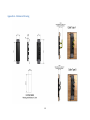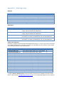
1
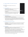
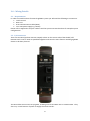
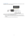
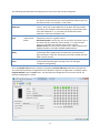
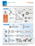
Glass Global / Off-Resume Touch Control dg02 User Manual Installation Manual George summers close, Medway City Estate, Rochester, Kent ME2 4EL Tel: +44 (0)1634 290 772, Fax: +44 (0)1634 290 773 [email protected] www.energy-solutions.co.uk Copyrights 2012 Energy Solutions UK Ltd. All Rights Reserved This publication or parts thereof may not be reproduced in any form, by any method, for any purpose. For conditions of use and permission to use this manual for publication in other than the English language, contact Energy Solutions UK Ltd. ENERGY SOLUTIONS UK LTD. MAKES NO WARRANTY, EITHER EXPESSED OR IMPLIED, INCLUDING BUT NOT LIMITED TO ANY IMPLIED WARRANTIES OF MERCHANTABILITY OR FITNESS FOR A PARTICULAR PURPOSE, REGARDING THESE ENERGY SOLUTIONS PRODUCTS AND MAKES SUCH ENERGY SOLUTIONS PRODUCTS AVAILABLE SOLELY ON AN “AS IS” BASIS. IN NO EVENT SHALL ENERGY SOLUTIONS UK LTD. BE LIABLE TO ANYONE FOR SPECIAL, COLLATERAL, INCIDENTAL, OR CONSEQUENTIAL DAMAGES IN CONNECTION WITH OR ARISING OUT OF PURCHASE OR USE OF THESE ENERGY SOLUTIONS PRODUCTS. THE SOLE AND EXCLUSIVE LIABILITY TO ENERGY SOLUTIONS UK LTD., REGARDLESS OF THE FORM OF ACTION, SHALL NOT EXCEED THE PURCHASE PRICE OF THE ENERGY SOLUTIONS PRODUCTS DESCRIBED HERE IN. Energy Solutions UK Ltd. reserves the right to revise and improve its products as it sees fit. This publication describes the state of this product at the time of its publication and may not reflect the product at all times in the future. -1- Contents 1.0 Introduction .................................................................................................................................. 3 1.1 - Introduction to LightNET......................................................................................................... 3 1.2 - Glass Global / Off-Resume Touch Control (dg02) ................................................................... 3 2.0 - Using your global / off resume touch control............................................................................. 4 2.1 - Overview ................................................................................................................................. 4 2.2 - Switching Lights On ................................................................................................................. 4 2.3 - Switching Lights Off ................................................................................................................ 4 2.4 – Operation of other controls in the system............................................................................. 4 2.5 - Other Features ........................................................................................................................ 4 3.0 – Wiring Details ............................................................................................................................. 5 3.1 – Requirements ......................................................................................................................... 5 3.2 –I/O Connectors ........................................................................................................................ 5 3.3 – System wiring ......................................................................................................................... 6 4.0 – Installation.................................................................................................................................. 7 4.1 – Hollow Walls........................................................................................................................... 7 4.2 – Solid Walls .............................................................................................................................. 7 5.0 – Configuration and Addressing .................................................................................................... 8 Appendix A – Mechanical Drawing ................................................................................................... 10 Appendix B - Technical Data ............................................................................................................. 11 Appendix C – Ordering Codes ........................................................................................................... 12 -2- 1.0 Introduction 1.1 - Introduction to LightNET ES LightNET is a simple but powerful lighting control system with dimmer, mood and colour capability. Unique lighting effects can be created in individual areas as well as allowing remote control of sections or of the entire system. 1.2 - Glass Global / Off-Resume Touch Control (dg02) The glass style global / off-resume touch control provides a sleek and stylish way to switch areas or an entire system on or off using the LightNET lighting system. A standby touch sensor is provided for simplicity and ease of lighting control. The touch sensor is illuminated with a blue symbol to add a unique look to the control and also to help locate the switch in the dark. -3- 2.0 - Using your global / off resume touch control 2.1 - Overview There is one touch area on the global / off-resume control: 1. Standby 2.2 - Switching Lights On After power has been applied to the associated dimmer base units lighting will remain off (standby mode). To switch lighting on you press the standby touch area. When the standby touch area is pressed the lighting will ramp up to 75% brightness. Pressing the standby touch area for more than two seconds when in standby mode will switch lighting on to 75% brightness and any associated colour lighting will turn on to full brightness, white. 1 2.3 - Switching Lights Off When lighting is on, pressing the standby touch area switches the lighting off and the control will go into standby mode. The power button will go to a low level of brightness. At this point the control is in standby mode and consumes a very small amount of power. Consecutive presses of the standby touch area from standby will cause the lighting to resume to the previous level. This means that if any lighting circuits had been turned off by another control prior to the global control being operated, they will not switch back on until the respective control is operated again. 2.4 – Operation of other controls in the system If all base units associated with the global control are all switched off the control will go into standby mode. If any one of the associated base units are switched on by another control, for example a dimmer touch control, the global control will wake up from standby which is indicated by the illuminated standby LED. 2.5 - Other Features Tracking behaviour - Where there is more than one control associated with the same set of lights all controls will provide the same visual feedback via their LEDs. Control not configured - The power LED flashes rapidly if the control has not been programmed to control any base unit devices (i.e. it is not addressed). In order for the control to be operable it must be configured using the esNET Programmer and an esNET USB dongle (ep02). See the Configuration section of this manual for more details. No communication - If the touch control is configured correctly and powered up but the base unit it is paired with is not powered or the data bus cable is not connected, the control will stay in standby mode no matter what touch area is pressed. Pressing the power touch area will illuminate the LED briefly before going out again. -4- 3.0 – Wiring Details 3.1 – Requirements In order to assemble a basic functional LightNET system you will need the following at a minimum: Touch Control Base unit RJ12 communications cable (6P6C) 12 or 24V power supply e.g. battery. Please refer to Appendix C for part numbers and the system overview brochure for example system configurations. 3.2 –I/O Connectors There are two RJ12 (6 pole 6 contacts or 6p6c) sockets on the reverse side of the Global / OffResume touch control. Both are paralleled together and serve the same function enabling LightNET devices to be daisy-chained. The RJ12 cables are used for carrying data, enabling controls and base units to communicate. They also carry a small amount of power to supply the touch controls. -5- 3.3 – System wiring As LightNET is a bus system, devices may be configured and wired in virtually limitless ways and the example below shows a common configuration. The diagram shows a 4-channel LED/Halogen/RGB Driver (db21) base unit being controlled with four dimmer touch controls and a global on/off touch control. Base units usually have three parallel RJ12 connectors. Controls may be connected to any one of these connectors to help simplify wiring and avoid having to install RJ12 splitters into the system. RJ12 cabling should always be of the CAT3 twisted pair type. -6- 4.0 – Installation The touch switches may be mounted into either hollow or solid walls. A unique spring clip design has been developed to enable easy deployment into both types of installation providing invisible fixing. A diagram showing the dimensions of the control is shown in Appendix A. 4.1 – Hollow Walls For a hollow wall a cut-out of 34mm wide by 100mm tall must be carefully cut. The switch is then simply connected to the network cabling and inserted into the cut-out. The spring clips hold the switch securely in place. 4.2 – Solid Walls For solid wall installations a standard 135 x 75 x 35 metal back box should be sunk vertically into the wall. An aluminium adaptor plate should be screwed into the back box and plastered over leaving the exposed 34mm wide by 100mm tall cut-out for the touch switch to be clipped into. Please see Appendix C for ordering codes. -7- 5.0 – Configuration and Addressing The global / off-resume touch control is configured using the esNET Programmer Software and an esNET USB dongle (ep02). When a new control is connected with no configuration stored within it the following screen will be displayed: The following table describes the items displayed that are for information only: Parameter Module Example dg02 Firmware Unique ID V4.05 8MGJ3DPW esNET Class 6 (LightNET default) Description The product ID code read from the device. This describes the hardware type: 'dg' and hardware version: '02'. The firmware version running on the device. An automatically generated random unique device identifier used internally by esNET The esNET class for LightNET devices should always be set to 6 -8- The following table describes items displayed on the screen that must be configured: Parameter Module Info Example Lower deck Forward Addresses 1, 2, 4, 5, 6 Control Type Global Control / One-button power Power off delay 0 seconds Fade off timer 5 seconds Description Provides a 16 character text area where user specified detail about the device can be entered. This is stored within the device and may be read back later. For example, “Lower deck”. Up to 24 forward addresses may be selected for a global touch control. They refer to the addresses of the base units they will be controlling. For example if lower deck lighting is connected to base units with addresses 1, 2, 4, 5 and 6 you should select these addresses in the forward address tab. Selects between whether the control should act as a one button off/resume control or a global control. One button power control may only control up to four base units in the same way that a dimmer control would, i.e. it will turn base units on or off when the standby touch area is pressed. Global control can control up to 24 base units. When selected two additional options are made available detailed below. May be configured from 0 to 255 seconds. It determines the length of time after the standby touch area has been pressed that the lights will begin to fade off. During this period the standby LED will flash once per second. May be configured from 5 to 500 seconds. It determines the length of time taken between lights starting to turn off and lights completely extinguishing. Once the Module Info has been entered (if required), Forward Addresses have been selected and any other fields have been changed from their defaults if required, configuration is complete. Select Program Module from the Tools menu. This will write the configuration to the touch control. An example configuration is shown: -9- Appendix A – Mechanical Drawing -10- Appendix B - Technical Data Parameter Nominal Supply Voltage Max. Standby Current Operating Current Control Type Operating Temperature Range IP Rating Value 7.5 - 32V 600μA 8mA LightNET -40 - +85°C IP4X Notes at nominal 24V supply at nominal 24V supply -11- Appendix C – Ordering Codes Modules: Ordering Code ES.NET-GL-UP/DOWN/OFF ES.NET-GL-OFF/RESUME ES.NET-GL-RGB ES.NET-GL-MOOD ES.NET-RGB-DRIVER-V5 ES.NET-DIMMER-10A Description Glass dimmer touch control (du02) Glass global off/resume control (dg02) Glass RGB control (du12) Glass preset / mood touch control (dm02) 25A 4-channel / RGB base unit (db21) 10A Halogen lamp dimmer / voltage stabiliser (db01) Accessories: Ordering Code ES.NET-DRIVER-ESLED-350 ES.NET-DRIVER-ESLED-700 ES.NET-GL-MOUNT-3 ES.NET-GL-MOUNT-6 Description 350mA constant current driver for LED lamps, 12/24V nominal supply, fully dimmable with PWM driver. 700mA constant current driver for LED lamps, 12/24V nominal supply, fully dimmable with PWM driver. Mounting plate to enable 3-way glass style touch switches to be mounted in an industry standard 135 x 75 x 35 metal back box. Mounting plate to enable 6-way glass style touch switches to be mounted in an industry standard 135 x 75 x 35 metal back box. Cables and Connectors: All cables are high quality CAT3 cable with 6P6C RJ12 connectors, i.e. all six pins of the connectors are loaded and connected. Connectors are fully over moulded with strain relief to ensure cables survive being installed in harsh environments. Ordering Code C-UTP-RJ12-200-FLAT C-UTP-ES-RJ12/0.3M-YELL C-UTP-ES-RJ12/0.5M-YELL C-UTP-ES-RJ12/01M-YELL C-UTP-ES-RJ12/02M-YELL C-UTP-ES-RJ12/03M-YELL C-UTP-ES-RJ12/05M-YELL C-UTP-ES-RJ12/10M-YELL C-UTP-ES-RJ12/15M-YELL C-UTP-ES-RJ12/20M-YELL C-UTP-ES-RJ12/26M-YELL C-UTP-ES-RJ12/30M-YELL C-UTP-ES-RJ12/35M-YELL ADAPTOR-RJ12-T-6 WAY PATCH LEAD/COUPLER RJ12 Description 0.2m RJ12 flat patch cable, grey, not moulded. 0.3m RJ12 moulded patch cable, yellow 0.5m RJ12 moulded patch cable, yellow 1m RJ12 moulded patch cable, yellow 2m RJ12 moulded patch cable, yellow 3m RJ12 moulded patch cable, yellow 5m RJ12 moulded patch cable, yellow 10m RJ12 moulded patch cable, yellow 15m RJ12 moulded patch cable, yellow 20m RJ12 moulded patch cable, yellow 26m RJ12 moulded patch cable, yellow 30m RJ12 moulded patch cable, yellow 35m RJ12 moulded patch cable, yellow Two way RJ12 splitter, 1 male to 2 female. Coupler for joining two RJ12 patch leads. Cable Type B A A A A A A A A A A A A N/A N/A A range of white / RGB LED strips, lamps and other accessories are available to the parts listed above. Please contact [email protected] or call +44 (0) 1634 290772 for more details. Notes: Notes: www.energy-solutions.co.uk Distributor: Serial number: Version : 01 Data : 07/11/12 Energy Solutions UK Ltd Unit B Future Court, George Summers Close Medway City Estate, Rochester Kent, ME2 4EL General phone : +44 (0) 1634 290772 Fax : +44 (0) 1634 290773 E-Mail : [email protected] Energy Solutions (UK) Ltd. Reg No. 2904541 Registered office: George Summers Close, Medway City Estate, Rochester, Kent, ME2 4EL