1
ACE II
Advanced Cryogenic Electronics
USER’S MANUAL
HP-307
September 2009
HP-307
July 2015
Notice
HOFFER FLOW CONTROLS, INC. MAKES NO WARRANTY OF ANY KIND
WITH REGARD TO THIS MATERIAL, INCLUDING, BUT NOT LIMITED TO,
THE IMPLIED WARRANTIES OF MERCHANTABILITY AND FITNESS FOR A
PARTICULAR PURPOSE.
This manual has been provided as an aid in installing, connecting, calibrating, operating, and
servicing this unit. Every precaution for accuracy has been taken in the preparation of this
manual; however, HOFFER FLOW CONTROLS, INC. neither assumes responsibility for any
omissions or errors that may appear nor assumes liability for any damages that may result from
the use of the products in accordance with information contained in the manual.
HOFFER FLOW CONTROLS' policy is to provide a user manual for each item supplied.
Therefore, all applicable user manuals should be examined before attempting to install or
otherwise connect a number of related subsystems.
During installation, care must be taken to select the correct interconnecting wiring drawing. The
choice of an incorrect connection drawing may result in damage to the system and/or one of the
components.
Please review the complete model number of each item to be connected and locate the appropriate
manual(s) and/or drawing(s). Identify all model numbers exactly before making any connections.
A number of options and accessories may be added to the main instrument, which are not shown
on the basic user wiring. Consult the appropriate option or accessory user manual before
connecting it to the system. In many cases, a system wiring drawing is available and may be
requested from HOFFER FLOW CONTROLS.
This document contains proprietary information, which is protected by copyright. All rights are
reserved. No part of this document may be photocopied, reproduced, or translated to another
language without the prior written consent of HOFFER FLOW CONTROLS, INC.
HOFFER FLOW CONTROLS’ policy is to make running changes, not model changes,
whenever an improvement is possible. This affords our customers the latest in technology and
engineering. The information contained in this document is subject to change without notice.
RETURN REQUESTS / INQUIRIES
Direct all warranty and repair requests/inquiries to the Hoffer Flow Controls Customer Service Department, telephone
number (252) 331-1997 or 1-800-628-4584. BEFORE RETURNING ANY PRODUCT(S) TO HOFFER FLOW
CONTROLS, PURCHASER MUST OBTAIN A RETURNED MATERIAL AUTHORIZATION (RMA) NUMBER FROM
HOFFER FLOW CONTROLS’ CUSTOMER SERVICE DEPARTMENT (IN ORDER TO AVOID PROCESSING
DELAYS). The assigned RMA number should then be marked on the outside of the return package and on any
correspondence.
FOR WARRANTY RETURNS, please have the
FOR
NON-WARRANTY
REPAIRS
OR
following information available BEFORE contacting
CALIBRATIONS,
consult
HOFFER
FLOW
HOFFER FLOW CONTROLS:
CONTROLS for current repair/calibration charges. Have
1. P.O. number under which the product was
the following information available BEFORE contacting
HOFFER FLOW CONTROLS:
PURCHASED,
1. P.O. number to cover the COST of the
2. Model and serial number of the product under
warranty, and
repair/calibration,
3. Repair instructions and/or specific problems relative
2. Model and serial number of the product, and
to the product.
3. Repair instructions and/or specific problems relative
to the product.
HFC 9708
LIMITED WARRANTY
HOFFER FLOW CONTROLS, INC. ("HFC") warrants HFC's products ("goods") described in the specifications incorporated in this
manual to be free from defects in material and workmanship under normal use and service, but only if such goods have been properly
selected for the service intended, properly installed and properly operated and maintained. This warranty shall extend for a period of
one (1) year from the date of delivery to the original purchaser (or eighteen (18) months if the delivery to the original purchaser
occurred outside the continental United States). This warranty is extended only to the original purchaser ("Purchaser"). Purchaser's
sole and exclusive remedy is the repair and/or replacement of nonconforming goods as provided in the following paragraphs.
In the event Purchaser believes the goods are defective, the goods must be returned to HFC, transportation prepaid by Purchaser,
within twelve (12) months after delivery of goods (or eighteen (18) months for goods delivered outside the continental United States)
for inspection by HFC. If HFC's inspection determines that the workmanship or materials are defective, the goods will be either
repaired or replaced, at HFC's sole determination, free of additional charge, and the goods will be returned, transportation paid by
HFC, using the lowest cost transportation available.
Prior to returning the goods to HFC, Purchaser must obtain a Returned Material Authorization (RMA) Number from HFC's
Customer Service Department within 30 days after discovery of a purported breach of warranty, but no later than the warranty
period; otherwise, such claims shall be deemed waived. See the Return Requests/Inquiries Section of this manual.
If HFC's inspection reveals the goods are free of defects in material and workmanship or such inspection reveals the goods were
improperly used, improperly installed, and/or improperly selected for service intended, HFC will notify the purchaser in writing and
will deliver the goods back to Purchaser upon (i) receipt of Purchaser's written instructions and (ii) the cost of transportation. If
Purchaser does not respond within thirty (30) days after notice from HFC, the goods will be disposed of in HFC's discretion.
HFC does not warrant these goods to meet the requirements of any safety code of any state, municipality, or other jurisdiction, and
Purchaser assumes all risk and liability whatsoever resulting from the use thereof, whether used singly or in combination with other
machines or apparatus.
This warranty shall not apply to any HFC goods or parts thereof, which have been repaired outside HFC's factory or altered in any
way, or have been subject to misuse, negligence, or accident, or have not been operated in accordance with HFC's printed
instructions or have been operated under conditions more severe than, or otherwise exceeding, those set forth in the specifications for
such goods.
THIS WARRANTY IS EXPRESSLY IN LIEU OF ALL OTHER WARRANTIES, EXPRESSED OR IMPLIED,
INCLUDING ANY IMPLIED WARRANTY OF MERCHANTABILITY OR FITNESS FOR A PARTICULAR
PURPOSE. HFC SHALL NOT BE LIABLE FOR ANY LOSS OR DAMAGE RESULTING, DIRECTLY OR INDIRECTLY, FROM THE USE
OR LOSS OF USE OF THE GOODS. WITHOUT LIMITING THE GENERALITY OF THE FOREGOING, THIS EXCLUSION FROM
LIABILITY EMBRACES THE PURCHASER'S EXPENSES FOR DOWNTIME OR FOR MAKING UP DOWNTIME, DAMAGES FOR WHICH
THE PURCHASER MAY BE LIABLE TO OTHER PERSONS, DAMAGES TO PROPERTY, AND INJURY TO OR DEATH OF ANY
PERSONS. HFC NEITHER ASSUMES NOR AUTHORIZES ANY PERSON TO ASSUME FOR IT ANY OTHER LIABILITY IN
CONNECTION WITH THE SALE OR USE OF HFC'S GOODS, AND THERE ARE NO ORAL AGREEMENTS OR WARRANTIES
COLLATERAL TO OR AFFECTING THE AGREEMENT. PURCHASER'S SOLE AND EXCLUSIVE REMEDY IS THE REPAIR AND/OR
REPLACEMENT OF NONCONFORMING GOODS AS PROVIDED IN THE PRECEDING PARAGRAPHS. HFC SHALL NOT BE LIABLE FOR
ANY OTHER DAMAGES WHATSOEVER INCLUDING INDIRECT, INCIDENTAL, OR CONSEQUENTIAL DAMAGES.
Disclaimer
Specifications are subject to change without notice.
Some pages are left intentionally blank.
HFC 9708
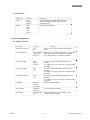
Contents
Contents ................................................................................................................................................ i
Specifications ........................................................................................................................................1
Overview ...............................................................................................................................................3
System Description ................................................................................................................... 3
Front Panel ................................................................................................................................ 3
Model Number .....................................................................................................................................5
Operation ..............................................................................................................................................7
Front Panel Operation ............................................................................................................... 7
Display parameters ................................................................................................................... 8
Contrast Adjust ......................................................................................................................... 8
Displaying Base Conditions ........................................................................................................................... 8
Displaying Software Version.................................................................................................... 8
Printing...................................................................................................................................... 8
Ticket Asterisks ........................................................................................................................ 9
Trip Report................................................................................................................................ 9
Error Log................................................................................................................................... 9
Audit Trail................................................................................................................................. 9
Clearing..................................................................................................................................... 9
Auto Clear Feature.................................................................................................................. 10
Error and Custom Messages ................................................................................................... 10
Passwords................................................................................................................................ 10
Diagnostics.............................................................................................................................. 10
One-Minute Start Phase .......................................................................................................... 10
Pump Interlock Option............................................................................................................ 10
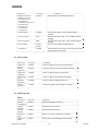
Pump Service Timer ............................................................................................................... 11
Pulse Security.......................................................................................................................... 11
CO2 Delivery........................................................................................................................... 11
Net Accumulated Total ........................................................................................................... 12
Programming........................................................................................................................... 12
Reviewing Settings ................................................................................................................. 13
Editing Program Settings ........................................................................................................ 13
Menu Structure ..................................................................................................................................15
Program Menu ........................................................................................................................ 16
Menu Fields ............................................................................................................................ 19
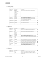
1. I/O Configuration................................................................................................................ 21
2. System Configuration ......................................................................................................... 23
3. Channel Configuration........................................................................................................ 26
4. Meter Configuration............................................................................................................ 27
ACEII / PROVER Users......................................................................................................... 29
HP-307
i
ACE II User’s Manual
Diagnostics ..........................................................................................................................................31
Diagnostics Menu ................................................................................................................... 31
Coil Resistance ....................................................................................................................... 31
RTD/ Analog Input ................................................................................................................. 31
Analog Output......................................................................................................................... 32
Digital I/O ............................................................................................................................... 33
Pulse Output............................................................................................................................ 34
Heater Sensor .......................................................................................................................... 34
Base Conditions ...................................................................................................................... 34
Communications ................................................................................................................................35
Function Code 04 (Read Input Registers)............................................................................... 35
Funtion Code 01 (Coil Status) ................................................................................................ 35
Installation ..........................................................................................................................................37
Location of the ACE II ........................................................................................................... 37
Cable Installation .................................................................................................................... 37
ACE II Program Setup ............................................................................................................ 37
Printer Installation................................................................................................................... 37
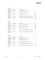
WinConfig Program ..........................................................................................................................39
Installation............................................................................................................................... 39
Startup ..................................................................................................................................... 39
Print......................................................................................................................................... 40
Configuration .......................................................................................................................... 40
I/O Configuration Menu ......................................................................................................... 40
Pump Interlock Option............................................................................................................ 41
Meter Configuration Menu ..................................................................................................... 42
Channel Configuration Menu ................................................................................................. 43
System Configuration Menu ................................................................................................... 44
Print Menu .............................................................................................................................. 45
ACE Menu ............................................................................................................................. 46
Downloading the Configuration ............................................................................................. 47
Configuration Files ................................................................................................................. 47
Saving Configuration Files ..................................................................................................... 47
Opening Configuration Files................................................................................................... 47
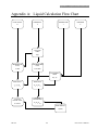
Appendix A: Liquid Calculation Flow Chart................................................................................49
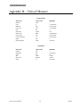
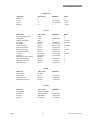
Appendix B: Units Of Measure ......................................................................................................50
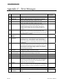
Appendix C: Error Messages..........................................................................................................53
Appendix D: Reference Densities ...................................................................................................54
Appendix E: Changing the Display Language ..............................................................................55
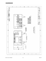
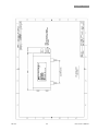
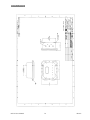
Appendix F: Drawings.....................................................................................................................56
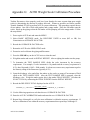
Appendix G: ACEII Weight Scale Calibration Procedure ...........................................................71
HP-307
ii
ACE II User’s Manual
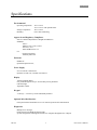
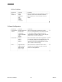
Specifications
Specifications
Environmental
Operating Temperature:
Storage Temperature:
Humidity:
-20C to 70C
-30C to 70C with optional heater
-40C to 85C
0-95% Non-condensing
Approvals and Regulatory Compliance
State of California Department of Weights and Measures
Standards:
AGA 7
OIML Tc 8 Sc 7, R117, R118
ISO 6551, 7637
NIST Handbook 44, 3.37
CE
Emissions EN55011
Immunity EN61326
Enclosure
NEMA 4X
Optional Explosion Proof,
Power Supply
8 to 30 Volts DC, 400mA max
Optional 110/220 VAC, 50/60Hz, 250/500 mA
Display
128x64 graphical display
Easy scroll through list of up to 14 selectable process parameters
LED back light
Adjustable contrast
Keypad
3 soft keys + 2 arrow keys can be individually disabled
Optional Infra-Red Interface
Front panel infrared transmitter/receiver for remote operation and communication
Diagnostics
Multiple error messages
Failure detection for RTD and analog inputs
System configuration and diagnostics from a PC computer through RS-232 or IR port
HP-307
1
ACE II User’s Manual
Specifications
Flow Compensation and Calculation Methods
5-point flow meter linearization
Up to 4 fluid properties tables
Security Features
Audit Trail with Time/Date/ID/New value/Old value for configuration changes
Flow Meter Input
Magnetic coil
Frequency range: 0.2 to 5,000 Hz.
Amplitude: 10mVrms to 50Vrms
Temperature Input
RTD selectable 100, 1000, 2500 Ohms
Accuracy 0.025%
Resolution 12 bit
Over voltage and over current protected
Analog Output
12 bit true D/A
Selectable 4-20mA, 1-5V
Pump Interlock Relay
240 Vac, 5A max.
RS232 Port
Printing or communication with a personal computer
Pressure Input
12 bit resolution
Selectable 4-20mA, 1-5V
Pulse Output
200 Hz max scaled to volume or mass units
0-5 V TTL, Open collector 30 Vdc, 250 mA max.
Clear Output
500mS pulse out
0-5 V TTL, Open collector 30 Vdc, 250 mA max.
Pulse Security Input
Quadrature input for magnetic coil, ISO6551 level B compliant
Frequency range: 0.2 to 5,000 Hz.
Amplitude: 10mVrms to 50Vrms
ACE II User’s Manual
2
HP-307
Overview
Overview
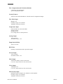
System Description
The ACE II, Advanced Cryogenic Electronics, is a truck mounted flow metering system for delivery of
cryogenic fluids. The system uses an internal computer to record and display deliveries in the required units.
An optional printer allows the system to print delivery information and ACE II setup parameters. ACE has
been designed to meet the requirements of the cryogenic metering section of NIST HANDBOOK 44 and
OIML R-81. Typical ACE II system consists of a turbine flowmeter, flow computer, a metering run mounted
on the delivery truck, and an optional printer.
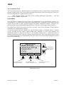
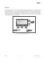
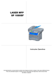
Display
12345678
TOTAL
GAL
Coil Open
PRINT
MENU
Scroll keys
CLEAR
Soft keys
Optional Infra-red window
ACE II Front Panel
Front Panel
The ACE II flow computer has a graphical display with 64x128 pixel resolution. The display is divided into
three sections: the upper section displays delivery total and other delivery parameters, the center section
displays error and custom messages, and the lower section displays labels for the three software-controlled
keys (soft-keys).
Below the display are three soft-keys, which functions vary with the ACE II mode of operation. The soft-key
labels, which are displayed above the keys, change according to the keys function. On the right side of the
display are the Up and Down SCROLL keys. These keys are used to select display parameters, and to navigate
through the configuration menu. Under the SCROLL keys is an infrared window for communicating with a
computer equipped with a compatible Serial to IR adapter or for printing to a model P7 printer.
HP-307
3
ACE II User’s Manual
Overview
This page intentionally left blank.
ACE II User’s Manual
4
HP-307
Model Number
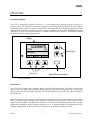
Model Number
The ACE II model number is provided by the Hoffer sales department based on the type of flow meter
pick up coils, hardware options installed, power supply, enclosure type, and accessories supplied with a
unit.
ACEII-(1T)-(P)-(7)-(PS)-(12)-(H)-(S)-(SP)
SPECIAL FEATURES
SERVICE
Volumetric Products
(1)
(2)
(3)
(4)
(5)
(6)
(7)
(V)
(X)
(SP) Any special features that
are not covered in the
model number
(W) Windows, based RS-232
serial port configuration
program with adapter
and cable
LIN/LOX/LAR
CO2
Nitrous Oxide
Liquid Hydrogen
LPG
LNG
(LIN/LNG/Ethylene
Volumetric
None
ENCLOSURE STYLE
(S)
Temperature/Pressure
Compensation and RTD inputs
(T)
(E)
Add T after the number of the
above product for temperature
compensation
(P) Add P after the number of all the
products for pressure compensation
(TP) Add TP after the number of
products for both temperature and
pressure
(T)
Standard-flat mount
with shocks
Tilt bracket with shocks
Explosion-Proof with 5
switches on cover
HEATERS OPTIONAL
(H) Heater required for
below 32°f
(X) No heater required
POWER INPUT
(12)
12Vdc power input, 12 Vdc
battery input
(24) 24Vdc power input, 24 Vdc
battery input
(AC) 110/220 VAC input,
24Vdc power output
PUMP INTERLOCK
(PI) 240 VAC, IMAX 5 AMPS
(X) None
OUTPUT OPTION
Scaled Pulse or Analog Output
(1)
(2)
(7)
(8)
(X)
PULSE SECURITY INPUT
(PTB) OPTIONAL
Open Collector
TTL/CMOS
4-20mA output
1-5Vdc output
None
HP-307
(PS) Quadrature Input per ISO6551
level B complaint (requires
second mag coil on turbine)
(X) None
5
ACE II User’s Manual
Model Number
This page intentionally left blank.
ACE II User’s Manual
6
HP-307
Operation
Operation
NOTE: This section applies only to ACE II units that have already been programmed. For initial
programming and set up refer to the Menu Structure section of this manual.
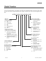
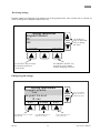
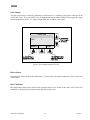
Front Panel Operation
1234567
M es s a g e
S e c tio n
TOTAL
C o il o p e n
P R IN T
GAL
MENU
CLEAR
U s e P R IN T k e y t o
U s e M E N U k e y to
p rin t d e liv e ry tic k e t e n te r th e m e n u
HP-307
7
U se S C R O L L
k e y s to s e le c t
d ip la y
U s e C L E A R k e y to
c le a r d e l i v e r y t o t a l
ACE II User’s Manual
Operation
Display parameters
The following process parameters are available for display and may be selected using the Windows
Configuration Program. Refer to the chapter on the WinConfig Program for more information on
setting the display parameters.
Parameter
Display
Frequency
V/Rate
FREQ
RATE
U/Rate
V/Total
U/RATE
TOTAL
U/Total
M/Rate
U/TOTAL
RATE
M/Total
TOTAL
M/Acc Total
V/Acc Total
U/Acc Total
Temp
ACTOT
ACTOT
U/ACTOT
TEMP
Press
PRES
Dens
DENS
Date and time
DATE
Description
Measured input frequency from turbine meter.
Flow rate, compensated to a selected reference condition, expressed
in units of volume.
Uncompensated flow rate, expressed in units of volume.
Compensated total, corrected to a selected reference condition,
expressed in units of volume. ACEII always defaults to the total
selected in Delivery Units.
Uncompensated total, expressed in units of volume.
Compensated flow rate based on fluid density, expressed in units of
mass.
Compensated total based on fluid density, expressed in units of
mass. ACEII always defaults to the total selected in Delivery
Units.
Accumulated compensated total expressed in units of mass.
Accumulated compensated total expressed in units of volume.
Accumulated uncompensated total, expressed in units of volume.
Measured flowing temperature. It will display a programmed
default temperature when default temperature is being used for
compensation, or “N/A” when temperature is not selected for
compensation.
Measured flowing pressure. It will display a programmed
default pressure whenever the default pressure is being used for
calculation, or “N/A” when pressure is not selected for
compensation.
Measured flowing density. It will display a programmed default
density whenever the default density is being used for
calculation, or “N/A” when density is not selected for
compensation.
Current Date and Time
Contrast Adjust
Display contrast can be adjusted using the SCROLL keys during the first 15 seconds after power up. A
message is displayed while the adjustment period is active. After the contrast adjustment period, the SCROLL
keys are used to select display parameters or to navigate in the program menu.
Displaying Base Conditions
To display current Base/Reference Conditions press MENU key, scroll to item number 5 (Base Conditions)
using the SCROLL key, and then press SELECT key.
Displaying Software Version
The software version number is displayed each time the ACE II is powered up.
Printing
Press the PRINT key to print a delivery ticket. A message will be displayed to ready printer. Press OK to print
delivery ticket. To select other items for printing press the MORE key. Select a desired item for printing
using SCROLL keys, and press the SELECT key. The printing function is available while flow is present.
ACE II User’s Manual
8
HP-307
Operation
ACE II detects when the printer is not connected, off line, or out of paper and displays a warning message.
Print Menu:
Ticket
Trip report
Error Log
Configuration data
Audit Trail
NOTE: To print to a Model P7 printer via the IR port, Print Enable must be set to Infrared in the Utility
Functions Menu.
Ticket Asterisks
Asterisks enclose the delivery total on all valid delivery tickets. If the feature is turned on, asterisks will be
removed from the delivery ticket if any of the selected errors occur during the delivery, and exceeds the set
accumulated error time. The errors can be viewed and selected in the Program/ System Configuration/ Utility
Functions menu and the ACE menu in the WinConfig program. Asterisks are always removed when the
delivery total does not reach the Minimum Delivery for a given meter size.
Trip Report
Trip Report registers stores up to 100 trip reports containing delivery information, and may be selected form
the Print menu.
Error Log
Error conditions are recorded in the error log. The error log can be printed; it cannot be viewed on the display.
Audit Trail
Audit Trail records changes made to ACE II that affect the Delivery Total. Each record consists of sequential
number, date, time, user ID, description of the field being changed, old value, and new value. The Audit Trail
stores up to 1000 records. The records of the audit trail can be printed. A message prompts user to enter the
number of records to be printed.
Clearing
To clear a delivery total press the CLEAR key. A message “Are you sure” will be displayed. Press YES key to
confirm clearing. After pressing the YES key to confirm, information stored in the register will be lost. Press
MORE key to select additional items for clearing.
Clear Menu: Total
Accumulated Total
Trip #
Clearing is not available while flow is present. A warning message will be displayed when the CLEAR key is
pressed while flow is present.
HP-307
9
ACE II User’s Manual
Operation
Auto Clear Feature
After printing a delivery ticket, ACE II automatically clears the delivery total when the next delivery begins.
Auto Clear feature is always active.
Error and Custom Messages
There are a number of warnings and error messages that guide the user in the event of an operational problem
or conflict in the configuration parameters. When error conditions occur an error message is displayed in the
message section of the display. If more then two error conditions occur simultaneously, the messages
automatically scroll every three seconds. Refer to Appendix D for a list of error messages.
The message section can be used to display custom messages including fluid name, base conditions,
compensation range. For further information on composing custom messages refer to the WinConfig section of
this manual. A custom message is replaced by an error message when error conditions occur.
Errors are recorded in the ACE II error log for future printing.
Passwords
The ACE II has two levels of password protection: operator and supervisor. At each level there are five user
ID numbers available. Any configuration parameter that may affect the flow calculation is protected with the
supervisor password. Operator password allows clearing of Accumulated totals only. The unit is shipped
unprotected, with all passwords set at 0000.
Diagnostics
To enter the diagnostic mode press MENU key, and select DIAGNOSTICS. Refer to Diagnostics section of
this manual for further information about the diagnostics functions.
One-Minute Start Phase
During the first minute of operation, errors are displayed but are not recorded in the error log. This OneMinute Start Phase begins with the first indication that flow is present.
Pump Interlock Option
Pump Interlock is an optional feature that disables the pump when gas phase is detected in the meter run.
ACE II uses a Pump Cool Down Timer and Gas Detection feature to enable or disable the Pump Relay. If the
Pump Interlock Option is selected, the temperature must drop below the Temperature Setpoint and liquid must
be present at the pump before the relay will be enabled. When using default temperature method, the value
assigned as the default temperature must be below the Temperature Setpoint for cool down to begin.
When the operating temperature drops below the programmed Setpoint value and liquid is detected, the Pump
Cooling Timer is displayed in the Message Window which indicates “Pump Cooling Down mm : ss ”. This
timer counts down from the programmed Delay Time value, enabling the Pump Relay when reaching zero.
ACEII will not totalize and errors will not be recorded until the temperature has dropped below the Setpoint
and the Pump Cooling Timer has reached 0. A Delay Time value of 0 disables the Pump Cooling Timer.
If at any time during the process gas is detected, the pump will be inhibited. This also applies to the OneMinute Start Phase. After the phase condition returns to a liquid state, ACE II will enable the Pump Interlock
Relay.
ACE II User’s Manual
10
HP-307
Operation
There is a list of errors available to be selected for Pump Deactivation. The Pump relay is inhibited if selected
errors exceed the programmed accumulated error time. The Accumulated Error Timer does not begin until the
One-Minute Start Phase has concluded. The errors are as follows:
Min Flow Error (50% of Min Flow Limit)
Max Flow Error
Pressure Signal Lost
Gas Inhibit
Compensation Range Error
Probe Short Error
Probe Open Error
Coil Short Error
Coil Open Error
Pump Service Timer
The pump service timer feature is designed to help with pump preventive maintenance schedule. When pump
is serviced or installed the user enters the service date, the type of service and the maximum number of pump
operational hours before the next service. ACE II will accumulate and display the total number of actual pump
operational hours. If the number of operational hours exceeds the set number of Max Operate Hours an error
message will be displayed. The error message will stay on until the actual hours display is reset to zero.
Pulse Security
ACEII provides an ISO6551 level B compliant quadrature input for pulse security. Error Detect must be
turned on in the FLOWMETER Menu under I/O CONFIGURATION for pulse security to be active. “Pulse
Frequency Error” will be displayed when an irregularity is detected on the input signal.
A dedicated input register is provided to count missing or double pulses deemed as “bad pulses”. The % of
Total During Error field in the UTILITY FUNCTIONS menu under SYSTEM CONFIGURATION is used to
set the maximum allowable error based on a percentage of the delivery total. If this limit is exceeded at
anytime during the delivery, “Bad Pulse Limit Exceeded” will be displayed in the message window. If the
message is displayed at the end of the delivery, the error will be reported in the error log and ticket asterisks
will be removed from the delivery ticket if this feature has been enabled. If the pump interlock option is
enabled, “bad pulses” are not counted until the temperature has dropped below the Temperature Setpoint and
the Pump Cooling Timer has reached 0.
CO2 Delivery
ACE II systems specified for CO2 service are equipped with a CO2 Single Pipe Fluid table and CO2 Dual
Pipe Fluid table. The following describes in what manner each should be used.
SINGLE PIPE: The SINGLE hose delivery counts all product delivered through the meter on the totalizer. No
correction is made for a vapor return or vapor balance line.
DUAL PIPE: A DUAL hose delivery occurs when a vapor return or vapor balance line is used in conjunction
with the liquid delivery line. When the DUAL pipe method is selected, the totalizer automatically deducts the
displaced vapor from the delivered total.
HP-307
11
ACE II User’s Manual
Operation
Net Accumulated Total
The net accumulated total is a difference between accumulated total after previous delivery and accumulated
total after current delivery. The net accumulated total represents amount of fluid lost during cool down cycle.
The net accumulated total is printed on the trip report.
NET ACCUM TOTAL =(ACCUM TOTAL AFTER PREVIOUS DELIVERY) – (ACCUM
TOTAL AFTER CURRENT DELIVERY)
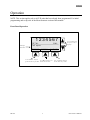
Programming
The ACE II unit is shipped from the factory fully programmed per user specification; however, it is
recommended to verify the program settings before installing the unit. Programming may be performed from
the ACE II front panel, or from a personal computer using Hoffer configuration software. Connection to a
personal computer may be established through the RS232 serial cable, or by using the infrared interface.
The program menu may not be entered while flow is present. This prevents parameters affecting the flow
calculations to be changed during a delivery.
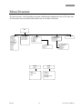
To enter the program mode press MENU key, and select Basic Settings or Advanced Settings. Software
versions 1.00.6300 and later contain a Basic Settings Menu which has all of the most frequently used
programming fields in a single top-level menu. The Advanced Settings menu is a multi-layer matrix of
submenus and contains some of the least frequently needed menu items. Refer to the Menu Structure section
for a detailed explanation of each programming field and a chart to assist in navigating through the menu to
locate a desired menu item.
M ain m en u
1. B asic S ettings
2. A dvanced S ettings
3. D iagnostics
4. P um p
S E LE C T
U se SELEC T key to
enter selected item
HOME
U se SC R O LL
keys to m ove
selection bar
E X IT
Use H O M E key to
return to operate screen
U se EX IT key to m ove
one level up
Main menu screen
ACE II User’s Manual
12
HP-307
Operation
Reviewing Settings
Program settings are displayed at the lowest level of the program menu. Once a menu item is selected, its
value or setting can be changed using the EDIT key.
Utility functions
K eypad tim eout
10
sec
ACCEPT
Use SCROLL
keys or numerical
keys to change
the value
ERASE
Use ERASE/CANCEL key
to return to review mode
without changing selection
Use ACCEPT key to accept
the selection and exit to
review mode
Editing Program Settings
U t ilit y f u n c t io n s
K e y p a d e n a b le
Yes
K e y p a d tim e o u t
10 sec
E D IT
U s e E D IT k e y to e n te r
e d it m o d e
HP-307
HOME
U s e H O M E k e y to
r e tu r n to m a in
13
U se S C R O LL
k e y s to m o v e
s e le c tio n b a r
E X IT
U s e E X IT k e y to
o n e le v e l u p
ACE II User’s Manual
Operation
This page intentionally left blank.
ACE II User’s Manual
14
HP-307
Menu Structure
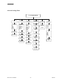
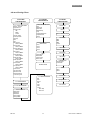
Menu Structure
The menu structure varies depending on options installed and configuration of the ACE II unit. Not
all of the menu items described in this manual may be available on all units.
MENU
1. BASIC SETTINGS
Serial Number
Delivery Units
Linearization
K-Factor Table
Average K-Factor
K-Factor Units
Frequency/ K-Factor 1-5
Last Service Date
Next Service Date
Trailer Number
Select Fluid
Fluid 1
Fluid 2
Fluid 3
Fluid 4
Date/Time
2. ADVANCED SETTINGS
1. I/O Configuration
2. System configuration
3. Channel configuration
4. Meter configuration
DIGITAL I/O
Prover in
Pump interlock
Clear out
CLEAR
Menu
Last Service Type
Hydraulic Motor Rebuilt
Motor Shaft Lube
Seal Replaced
Bearing Replaced
Pump Rebuilt
PRINT
Menu
1. Total
2. Accum Total
3.Trip #
HP-307
5. BASE CONDITIONS
4. PUMP SERVICE
Max Operating Hours
Hours Since Last Service
Last Service Date
Last Service Type
3. DIAGNOSTICS
1. Coil 1 resistance
2. RTD/Analog In
3. Analog out
4. Digital I/O
5. Pulse out
6. Heater sensor
1. Ticket
2. Trip report
3. Error log
4. Configuration data
5. Audit trail
15
ACE II User’s Manual
Menu Structure
Advanced Settings Menu
2.1. I/O CONFIGURATION
RTD
RTD TYPE
Off
100
1000
2500
DIN 100
Calibration P
Calibration Q
ANALOG IN
TYPE
On/Off
Pressure
Temperature
Density
Sp gravity
Flow
ANALOG OUT
TYPE
On/Off
Pressure
Temperature
Density
Sp gravity
Flow/U
Flow/V
Flow/M
DIGITAL I/O
Flowmeter
CLEAR OUT
ON/OFF
ERROR
DETECTION
ON/OFF
MODE
Off
Modbus
Printer
PULSE OUT
ON/OFF
Min value
Max value
RS232
Pulse scale
Min value
BAUD
1200
2400
4800
9600
19200
PUMP
INTERLOCK
ON/OFF
Max value
Calibration P
Calibration P
Temperature set
point
Calibration Q
Modbus
address
Calibration Q
Time delay
Pump Accum
Error Time
ACE II User’s Manual
16
HP-307
Menu Structure
Advanced Settings Menu
2.2. SYSTEM
CONFIGURATION
2.2.1. UTILITY FUNCTIONS
Remove * with error
Keypad time out
Print key enable
OFF
RS232
Infrared
Clear key enable
Scroll keys enable
Language
Date
Time
Min Flow Error
Interlock ON/OFF
Max Flow Error
Interlock ON/OFF
Pressure Signal Lost
Interlock ON/OFF
Gas Inhibit on
Interlock ON/OFF
Comp Range Error
Interlock ON/OFF
Probe Short Error
Interlock ON/OFF
Probe Open Error
Interlock ON/OFF
Coil Short Error
Interlock ON/OFF
Coil Open Error
Interlock ON/OFF
Trailer number
Last service date
Next service date
Select ticket format
% total durring error
2.2.2. PASSWORD/PIN
2.2.3. FLUID PROPERTIES
2.2.3.x. Fluid 1-4
Default Temp
Default Pres
Default Dens
Density at Base
Density at NBP
HP-307
2.3. CHANNEL
CONFIGURATION
COMPENSATION METHOD
None
Default temp
Defalul T&P
Default Density
Temp
Temp @ Default Press
Temp & Pressure
Density
SELECT FLUID
Fluid 1
Fluid 2
Fluid 3
Fluid 4
2.4. METER
CONFIGURATION
Serial Number
Filtering
Min Flow Meter Frequency
METER SIZE
DN25
DN40
DN50
Custom
Min Flowrate
UNITS
English default
Metric default
English custom
Metric custom
Max Flowrate
Min Delivery
LINEARIZATION
Average K-factor
K-factor table
DELIVERY UNITS
TABLE
Table 1
Table 2
2.2.4. BASE CONDITIONS
Nist
Oiml
Normal
PTB
Sirim
Asian
Custom
Base Temp
Base Pres
17
K-Factor Units
Average K Factor
K-Factor Table
ACE II User’s Manual
Menu Structure
This page intentionally left blank.
ACE II User’s Manual
18
HP-307
Menu Structure
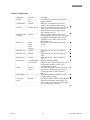
Menu Fields
This section describes the program menu fields in detail. Whenever applicable the description is presented in
the following format:
Menu Item
Selection
Comments
Paragraph numbers in this chapter correspond to the menu field numbers in the ACE II.
A program menu item can be accessed by pressing the MENU key and then using SCROLL and SELECT
keys as described in the Operation section of this manual.
Basic Settings
Software versions 1.00.6300 and later have a Basic Settings Menu containing the most frequently used
Program fields in an easy to access top-level menu.
1. BASIC SETTINGS
Menu
Selection
Comments
Serial Number
Number
Delivery Units
English Units
Gallons @ NBP
FT3 @ NTP
LBS
Metric Units
Liters @ NBP
M3 @ NTP
KG
Average K
K-Factor Table
Enter the Flowmeter serial number.
Alphanumeric entries can be made from
WinConfig, but cannot be edited from the
instrument.
Select the default units displayed for Delivery
Total. English / Metric units are available based
on the type of units selected in the Channel
Configuration in the Advanced Settings Menu.
Linearization
K-factor units
Average Kfactor
HP-307
Pulse / Gallon
Pulse / Liter
Pulse / FT3
Pulse / M3
Number
Select whether a single Average K-Factor is used
or a 5-point table of K-Factors over the
flowmeters operating range.
Select units of measure for K-factor.
Last Service
Date
This menu is displayed when Average K-factor
selected for linearization method. Enter a Kfactor for the meter connected to this channel.
Enter the last service date.
Next Service
Date
Enter the next service date.
Trailer number
Number
Enter trailer number. Alphanumeric entries can
be made from WinConfig, but cannot be edited
from the instrument.
19
ACE II User’s Manual
Menu Structure
Menu
Selection
Comments
Select fluid
Fluid 1
Fluid 2
Fluid 3
Fluid 4
Select a fluid table for the current application. Up
to four different fluids can be programmed in the
ACE II. Actual Fluid names will be displayed in
this menu if service was specified at the time or
order.
Date/Time
Enter date and
time
This menu is used to set time and date.
ACE II User’s Manual
20
HP-307
Menu Structure
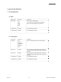
2. ADVANCED SETTINGS
1. I/O Configuration
1.1. RTD
Menu item
RTD Type
Selection
Off
100
1000
2500
DIN
Comments
Select a type of RTD probe.
100, 1000, 2500 are platinum 3902 material
DIN is 100 Ohm platinum 0385 material
Calibration P
Number
See calibration procedure
Calibration Q
Number
See calibration procedure
Menu item
Function
Selection
Off
Pressure
Temperature
Density
Sp gravity
Flow
Comments
Select a desired function for the analog input.
Min value
Number
Max value
Number
Calibration P
Number
Enter a number corresponding to the minimum
value for the input range, in the units selected for
the input.
Enter a number corresponding to the maximum
value for the input range, in the units selected for
the input
See calibration procedure
Calibration Q
Number
See calibration procedure
1.2. Analog Input
HP-307
21
ACE II User’s Manual
Menu Structure
1.3. Analog Output
Menu item
Function
Min value
Selection
Off
Pressure
Temperature
Density
Sp gravity
Flow/M
Flow/V
Flow/U
Number
Comments
Select a desired function for the analog output.
Max value
Number
Calibration P
Number
Enter a number corresponding to the minimum
value for the analog output range.
Enter a number corresponding to the maximum
value for the analog output range.
See calibration procedure.
Calibration Q
Number
See calibration procedure.
Selection
ON
OFF
Off
Pulse/U
Pulse/V
Pulse/M
Number
Comments
Select “ON” to enable the Clear Out function.
1.4. Digital I/O
Menu item
Clear out
Pulse Out
Pulse Out
Scale
Pump
Interlock
ON
OFF
Temp Set
Point
Time Delay
Number
Pump Error
Time
Number
Number
Select a desired function for the Pulse Out.
Enter a scaling factor for pulse out. “1” means one
pulse is output for each unit of measure.
Select “ON” to enable the Pump Interlock function.
Enter a temperature set point to be reached during
cool down cycle, before the timer starts counting.
Enter a time delay in seconds before pump relay is
enabled after reaching the temperature set point.
Enter Pump accumulated error time in seconds.
Refer to WinConfig program for a selection of
errors for Pump Interlock function.
1.5. Flowmeter
Menu item
Error Detect
ACE II User’s Manual
Selection
ON
OFF
Comments
Select “ON” to enable the pulse error detection
function. This function is available for dual coil
meters only.
22
HP-307
Menu Structure
1.6. RS232 Port
Menu item
Mode
Baud
Selection
Off
Modbus
Printer
1200
2400
4800
9600
19200
Comments
Select Modbus for communication with a PC
computer or Modbus master. Select Printer for
printing function.
Select a desired baud rate.
2. System Configuration
2.1. Utility Functions
Menu item
Selection
Yes
No
Enter a number
of seconds
Range: 0-
Comments
Select “Yes” to remove asterisks with selected
errors.
If the unit is left in the program mode, it will switch
back to the operate mode when limit is reached.
Zero means the time out function is disabled.
Print key enable
Off
RS232
Infrared
Clear key enable
Yes
No
Scroll Keys enable
Yes
No
Language
English
Spanish
Portuguese
mm/dd/yy
dd/mm/yy
Enter date and
time
If “No” is selected the front panel Print key is
disabled.
To enable, press any key and enter a password when
prompted.
If “No” is selected the front panel Clear key is
disabled.
To enable, press any key and enter a password when
prompted.
If “No” is selected the front panel Scroll keys is
disabled.
To enable, press any key and enter a password when
prompted.
Select a desired language.
Remove* with error
Keypad time out
Date Format
Date/Time
HP-307
Select a desired date format.
This menu is used to set time and date. Also
available in Basic Settings.
23
ACE II User’s Manual
Menu Structure
Menu item
Selection
Comments
Minimum Flow Error
Maximum Flow Error
Pressure Signal Lost
Gas Inhibit Error
Compensation Range Error
Probe Short Error
Probe Open Error
Coil Short Error
Coil Open Error
On/Off
Pump Interlock on / Pump Interlock off.
Trailer number
Number
Last service date
Date
Next service date
Date
Ticket format
Ticket 1
Ticket 2
Number
Enter trailer number. Also available in Basic
Settings.
Enter the last service date. Also available in Basic
Settings.
Enter the next service date. Also available in Basic
Settings.
Select a ticket format for printed tickets.
% total error
Enter allowable percentage of error for pulse security
function (pulse error detect).
2.2. Password/Pin
Menu item
Supervisor
pin #1-5
Reenter
password
Supervisor
password
Operator pin
#1-5
Operator
password
Reenter
password
Selection
Number
Comments
Enter a 4 digit for each supervisor pin number.
Number
Enter the supervisor password again to confirm.
Number
Enter a 4 digit for supervisor password.
Number
Enter a 4 digit for each operator pin number.
Number
Enter a 4 digit for operator password.
Number
Enter the operator password again to confirm.
2.3. Fluid Properties
Fluid 1
Menu item
Default
Temperature
Default
Pressure
Default
Density
Density at
Base
Density at
NBP
ACE II User’s Manual
Selection
Number
Comments
Default temperature for Fluid 1.
Number
Default pressure for Fluid 1.
Number
Default density for Fluid 1.
Number
Density at reference temperature for Fluid 1.
Number
Density at the normal boiling point for Fluid 1.
24
HP-307
Menu Structure
Fluid 2
Menu item
Default
Temperature
Default
Pressure
Default
Density
Density at
Base
Density at
NBP
Selection
Number
Comments
Default temperature for Fluid 2.
Number
Default pressure for Fluid 2.
Number
Default density for Fluid 2.
Number
Density at reference temperature for Fluid 2.
Number
Density at the normal boiling point for Fluid 2.
Selection
Number
Comments
Default temperature for Fluid 3.
Number
Default pressure for Fluid 3.
Number
Default density for Fluid 3.
Number
Density at reference temperature for Fluid 3.
Number
Density at the normal boiling point for Fluid 3.
Selection
Number
Comments
Default temperature for Fluid 4.
Number
Default pressure for Fluid 4.
Number
Default density for Fluid 4.
Number
Density at reference temperature for Fluid 4.
Number
Density at the normal boiling point for Fluid 4.
Fluid 3
Menu item
Default
Temperature
Default
Pressure
Default
Density
Density at
Base
Density at
NBP
Fluid 4
Menu item
Default
Temperature
Default
Pressure
Default
Density
Density at
Base
Density at
NBP
HP-307
25
ACE II User’s Manual
Menu Structure
2.4. Base Conditions
Menu item
Base
conditions
Selection
NIST
OIML
NORMAL
PTB
SIRIM
ASIAN
CUSTOM
Comments
Select a predefined set of base conditions, or select
“custom” to enter user defined base conditions.
Base conditions are used to calculate corrected
volume.
3. Channel Configuration
Menu item
Selection
Compensation Default temperature
method
Default T&P
Temperature
Temp & Default P
T&P
Density
Select fluid
Fluid 1
Fluid 2
Fluid 3
Fluid 4
Comments
Select an appropriate compensation method.
For T, P, D compensation an associated sensor has
to be connected and an analog input has to be
programmed accordingly. When a sensor fails, the
default value is used for calculations.
Units
Select a desired set of units of measure. For a
complete list of available units and conversion
factors refer to Appendix B.
ACE II User’s Manual
English default
English custom
Metric default
Metric custom
Select a fluid table for the current application. Up to
four different fluids can be programmed in the ACE
II. Actual Fluid names will be displayed in this
menu if service was specified at the time or order.
Also available in Basic Settings.
26
HP-307
Menu Structure
4. Meter Configuration
Menu item
On/off
Serial number
Selection
On
Off
Number
Filtering
Number (0-100)
Minimum meter
frequency
Number
Meter size
Min Flow rate
DN25
DN40
DN50
Custom
Number
Max Flow rate
Number
Min Delivery
Number
Linearization
Average K-factor
K-factor table
Table
Table 1
Table 2
K-factor units
Average Kfactor
HP-307
Number
Comments
“On” has to be selected to activate the flow
channel operation.
Enter up to a 10- digit flow meter serial
number. Also available in Basic Settings.
Enter a whole number between 0 and 100. This
number represents the amount of filtering
applied to the input signal coming from a
meter. Default value is 0.
Enter a frequency in Hz that is below an
operating range of input frequency. Any signal
at frequency below the Minimum value is
considered “noise” and it will be rejected.
Default value is 0.
Select meter size installed in the ACE II
system.
Enter Min Flow rate value for custom size
meter.
Enter Max Flow rate value for custom size
meter.
Enter Min Delivery value for custom size
meter.
Select an applicable method.
The menus below will be displayed only when
the associated method is selected. Also
available in Basic Settings.
Select K-Factor Table 1 or Table 2 to use for
linearization. Multiple tables allow for easy
switching between two different turbine
meters.
Select units of measure for K-factor. Also
available in Basic Settings.
This menu is displayed when Average K-factor
selected for linearization method. Enter a Kfactor for the meter connected to this channel.
Also available in Basic Settings.
27
ACE II User’s Manual
Menu Structure
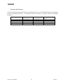
Flowmeter Size Selection
ACE II provides Flowmeter Size Selection in the Meter Menu to set values for Minimum Flowrate, Maximum
Flowrate, and Minimum Delivery. The following table lists the meter size options and the corresponding
parameters.
FLOWMETER SIZE
DN25
DN40
DN50
CUSTOM
ACE II User’s Manual
MIN FLOWRATE
L/min (gal/min)
46 (12.152)
100 (26.417)
170 (44.909)
User Defined
28
MAX FLOWRATE
L/min (gal/min)
230 (60.760)
500 (132.086)
850 (224.546)
User Defined
MIN DELIVERY
Kg (lbs)
10 (22.046)
100 (220)
100 (220)
User Defined
HP-307
Menu Structure
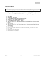
ACEII / PROVER Users
NOTE: Hoffer Flow Controls recommends programming the ACEII with a 5-point K-Factor table as
calculated by the prover calibration and indicated on the Final Calibration Report printout.
After all 5 prover calibration points have been calculated, the new K/M-FACTOR must be entered
into the ACEII from the METER CONFIGURATION menu using the following procedure.
1.
2.
3.
4.
5.
6.
Press MENU
Select BASIC SETTINGS
SCROLL down to LINEARIZATION and press EDIT
Select K-FACTOR TABLE and press ACCEPT
SCROLL down to TBL1 POINT #1 – FREQ
EDIT TBL1 POINT #1 – FREQ and enter point #1 Freq from the Final Calibration Report
printout
7. Press ACCEPT
8. EDIT TBL1 POINT #1 – FACTOR and enter point #1 K-Factor from the Final Calibration
Report printout
9. Press ACCEPT
10. Continue entering the calibration data in this manner until all 5 points have been entered
11. Press HOME
12. Select YES at Save Data prompt
13. Select RESET at Reset prompt
HP-307
29
ACE II User’s Manual
Menu Structure
This page intentionally left blank.
ACE II User’s Manual
30
HP-307
Diagnostics
Diagnostics
Diagnostics Menu
ACE II provides diagnostic functions for testing Inputs and Outputs to verify hardware functionality. To
access Diagnostics functions press MENU, scroll to Diagnostics, and press SELECT.
Diagnostics functions:
Coil Resistance
RTD/Analog In
Analog Out
Digital I/O
Pulse Out
Heater Sensor
Coil Resistance
The coil resistance diagnostic displays the resistance measurement ( 10 %) of the flowmeter pickup coil in
Ohms. Normal coil resistance should be in the range of 1500 – 2500 Ohms.
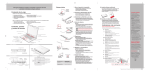
RTD/ Analog Input
RTD and Analog diagnostic screen displays the A/D (analog to digital converter) counts for both the RTD
input and the Analog Input (AI). A/D counts for a configured input should always be between 0 and 4095
during normal operation. As the transmitter signal increases, the number of A/D counts should also increase.
As the RTD temperature increases, the number of A/D counts should also increase. If the count displayed is 0
or 4095, it means that either the input has not been configured or calibrated, or there is an RTD or Transmitter
failure.
AI
RTD
AI
1255
2354
EXIT
Use EXIT key to move
up to Diagnostics Menu
Figure 2. RTD/Analog Input Diagnostics Screen
HP-307
31
ACE II User’s Manual
Diagnostics
Analog Output
The Analog Output may be tested by connecting a milliamp meter, to pins A and B of the analog output
connector located on the ACE II rear panel. Pressing the SELECT key selects the output. Use the SCROLL
keys to increase or decrease the number of D/A counts. As the number increases, the output current should
increase. As the number decreases, the output current should decrease. The range of D/A counts is from 0 to
4095. At 0 counts the output current should be close to 4 mA; at 4095 the current should be close to 20 mA.
AO
Use SCROLL
keys to increase
or decrease the
number of D/A
counts
AO: 0
SELECT
EXIT
Use SELECT to
highlight the
output
Use EXIT to move up
to the Diagnostics
main menu
Figure 3. Analog Output Diagnostics Screen.
ACE II User’s Manual
32
HP-307
Diagnostics
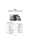
Digital I/O
The Digital I/O diagnostics is used to verify operation of the digital inputs and outputs. The state of the Prover
input is displayed as a 1 or a 0. A 1 represents a high signal level and 0 a low signal level. When a signal is
applied to an input, the corresponding digit will toggle accordingly. For the Pump Interlock and Clear
Outputs, press SELECT to highlight the desired output and use the SCROLL keys to toggle the output
between high and low levels. The output may be monitored with a meter connected to the corresponding
output connector on the ACE II rear panel.
Prover In(I):
DIO
1
Pump Intlk (O):
1
Clear (O):
1
SELECT
Use SCROLL
keys to toggle
the outputs
EXIT
Use EXIT key to move
up to the Diagnostics
Main Menu
Use SELECT key to highlight
the desired output
Figure 4. Digital I/O Diagnostics Screen
HP-307
33
ACE II User’s Manual
Diagnostics
Pulse Output
The pulse output may be tested by connecting an oscilloscope or a voltmeter to the output connector on the
ACE II rear panel. Press the SELECT key to highlight the output and the SCROLL Keys toggle the output
between high and low states. A 1 outputs a high signal and a 0 outputs a low signal.
Pulse Out
Out
Use SCROLL
keys to toggle
the output
1
SELECT
EXIT
Use EXIT key to move
up to the Diagnostics
Main Menu
Use SELECT key to
highlight the output
Figure 5. Pulse Output Diagnostics Screen.
Heater Sensor
This diagnostic feature displays the temperature (C) measured by the digital temperature sensor on the ACE
II front panel.
Base Conditions
Base temperature and pressure selected in the program menu can be viewed in this menu. ACE II uses base
conditions to calculate corrected total volume and corrected flow rate.
ACE II User’s Manual
34
HP-307
Communications
Communications
ACE II is equipped with RS232 serial port and the optional infra-red port. The serial port has to be configured
for either printing or Modbus functions in the ACE menu at Program/IO Configuration/RS232. It can be used
for printing, programming the ACE II settings, communication with a personal computer, or with a Modbus
master device. For programming ACE II from a personal computer using Hoffer configuration program, refer
to the WinConfig section of this manual.
ACE II supports standard MODBUS RTU (binary) encoding. The following tables list Modbus addresses for
the available Modbus commands.
Function Code 04 (Read Input Registers)
ABSOLUTE ADDRESS
30001
30002
30003
30004
30005
30006
30007
30008
30009
30010
30011
30012
30013
30014
30015
30016
DESCRIPTION
Uncorrected Rate (X1, X10, X100 or X1000)
High Word of Uncorrected Total
Low Word of Uncorrected Total (X1, X10, X100
or X1000)
High Word of Uncorrected Accum Total
Low Word of Uncorrected Accum Total
Corrected Rate (Mass or Volume) (X1, X10,
X100 or X1000)
High Word of Corrected Total
Low Word of Corrected Total (X1, X10, X100 or
X1000)
High Word of Corrected Accum Total
Low Word of Corrected Accum Total
Pressure
Density X 1000
Temperature (Kelvin)
OPEN
OPEN
OPEN
Function Code 01 (Coil Status)
ABSOLUTE ADDRESS
00002-00008
00009
00010
HP-307
DESCRIPTION
OPEN
Clear Totals
Clear Accum Totals
35
ACE II User’s Manual
Communications
This page intentionally left blank.
ACE II User’s Manual
36
HP-307
Installation
Installation
This section includes information specific to the ACE II flow computer installation. For installation
information on the turbine flowmeter, temperature probe, pressure probe, or other equipment refer to the
individual item’s technical manuals.
Location of the ACE II
The ACE should be mounted at operator eye-level for the best viewing angle. Install the ACE on a horizontal
surface near the access door of the trailer. Allow enough clearance for easy access to the signal cables.
CAUTION !
ACE II MUST BE INSTALLED IN THE HORIZONTAL POSITION. MOUNTING IN THIS POSITION IS
CRITICAL TO ALLOW THE SHOCK MOUNTS TO FUNCTION PROPERLY AND PREVENT DAMAGE CAUSED
BY TRUCK VIBRATION.
WARNING !
DO NOT OVER-TIGHTEN MOUNTING BOLTS. RECOMMENDED TIGHTENING TORQUE IS 105 LBS-IN.
OVER-TIGHTENING MAY CAUSE SHOCK MOUNTS TO BREAK.
Cable Installation
Install and secure cables to avoid contact with cold pipes.
Attach cables to the appropriate connector on the back of the ACE.
The power cable is a three-wire cable. Red lead connects to positive (+) battery lead.
Black lead connects to negative (-) lead. White lead connects to chassis ground.
The ACE has no power switch. Hoffer recommends providing the ACE II with a direct
power lead from the battery. This will reduce interference from other operating systems.
If a switch is required, HFC recommends using the main power switch on the trailer.
Install dust caps on any unused connections.
Tighten all cable assemblies.
ACE II Program Setup
After the installation of components is complete, the setup parameters must be reviewed prior to using the
ACE II for customer delivery.
Printer Installation
The ACE II printer requires two cables for proper operation; one for connection to the ACE II RS232 port and
the other for connection to the DC power supply.
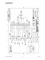
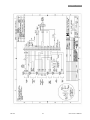
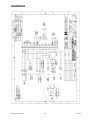
For further information on the ACE II installation refer to the installation drawings located in the back of this
manual.
HP-307
37
ACE II User’s Manual
Installation
This page intentionally left blank.
ACE II User’s Manual
38
HP-307
WinConfig Program
WinConfig Program
The Nova-Flow WinConfig Program allows for quick, easy configuration of the ACE II using a personal
computer. All programmable fields available locally on the ACE II are also accessible through the WinConfig
program. This chapter provides guidelines for basic operations available through WinConfig.
Installation
Minimum system requirements:
486 Processor running Windows 95/NT and a Communications Port.
Installation:
Insert the provided disk into the computer.
Click on the “Start” menu on the Windows desktop taskbar and select “Run”.
Click on “Browse” and search for the drive in which the disk is located.
Select “Setup”, and let the Setup Wizard guide the installation process.
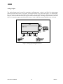
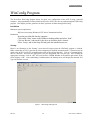
Startup
Below is an illustration of the “Startup” screen that will appear when the WinConfig program is invoked.
Make certain that ACE II is powered up before attempting to establish communications. Connection may be
made to the ACE II via RS-232 communications cable or the infrared interface. Click on “Communications”
then on “Initialize” and select the appropriate Com port designation and Com port type. After making the
appropriate selections, click on “OK” and verify that the COMM Window in the bottom right corner of the
screen displays “OK”. After establishing Communications, the Startup screen will display the detected Unit
Type and software version.
Figure 1. WinConfig Startup Screen
HP-307
39
ACE II User’s Manual
WinConfig Program
Print
Clicking on “Print” in the Startup screen will print a copy of the programmed configuration parameters to a
printer connected to the personal computer. A preview of the printout may be displayed by selecting “File”
and then “Print Preview”.
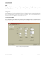
Configuration
After communications have been established, clicking on “Configuration” uploads program information from
ACE II. Once the upload is complete, the I/O menu will be displayed. Other available menu items may be
selected by clicking on the appropriate tabs at the top of the screen.
I/O Configuration Menu
The I/O Configuration Menu consists of two sub menus, Analog I/O and Digital I/O. The Configuration Menu
is used to assign, configure, and calibrate inputs and outputs. Some diagnostic functions are also available in
the I/O Menu.
Figure 2. Analog I/O Configuration Menu.
ACE II User’s Manual
40
HP-307
WinConfig Program
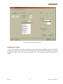
Figure 3. Digital I/O Configuration Menu.
Pump Interlock Option
A list of error conditions is provided, so that the user may select specific operational errors that will disable
the pump relay and/or remove asterisks from the ticket printout. When the selected operating error occurs for
a period exceeding the entry in the Errors Accumulated Time field, the pump relay will be disabled and flow
stopped.
HP-307
41
ACE II User’s Manual
WinConfig Program
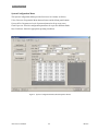
Meter Configuration Menu
The Meter Configuration Menu is used to configure all parameters associated with the connected flow
meter(s). Included in this menu are fields for the meter serial number, meter size settings, and linearization
parameters.
Figure 4. Meter Configuration Menu.
ACE II User’s Manual
42
HP-307
WinConfig Program
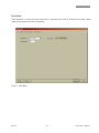
Channel Configuration Menu
The Channel Configuration Menu is used to configure metrological specifics such as compensation methods,
fluid selection and unit selections. Modbus multipliers are
available for Total and Flowrate to increase the resolution of data retrieved via serial Modbus
communications. See the Communications chapter for more information on Modbus protocol.
Figure 5. Channel Configuration Menu.
HP-307
43
ACE II User’s Manual
WinConfig Program
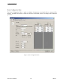
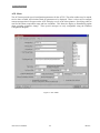
System Configuration Menu
The System Configuration Menu provides four lower level menus as follows:
Utility Functions: Program the Menu timeout feature and lock front panel buttons.
Password/Pin: Program two levels of password protection for up to ten users.
Fluid Properties: Provides configuration parameters for up to four different fluids.
Base Conditions: Select the appropriate operating conditions.
Figure 6. System Configuration Menu (Fluid Properties Shown).
ACE II User’s Manual
44
HP-307
WinConfig Program
Print Menu
The Print Menu is used to select the printer that is connected to the ACE II, define the associated column
width, and select the ticket format for printing.
Figure 7. Print Menu.
HP-307
45
ACE II User’s Manual
WinConfig Program
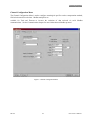
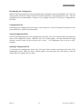
ACE Menu
The ACE menu provides special configuration parameters for the ACE II. The trailer number may be entered,
service dates recorded, and selections made for parameters to be displayed. There is also a tool to configure
custom messages that will appear on the ACE II display as well as the ticket printout. Specifying codes are
used for fluid name, temperature range and base conditions. This allows the display to automatically update
when operating parameters change. These special messages are only configurable using the Windows
Configuration Program.
Figure 8. ACE Menu.
ACE II User’s Manual
46
HP-307
WinConfig Program
Downloading the Configuration
When all required parameters have been programmed, the configuration may be downloaded to the ACE II by
clicking on the “Download” button located in the bottom right corner of the configuration screens. After the
configuration has been downloaded, a software reset is required on the ACE II for the new configuration to
take affect.
Configuration Files
WinConfig allows configurations to be saved as a file for future use. The two available file functions are File
Open and File Save, which are described below.
Saving Configuration Files
After all required parameters have been programmed, click on the “File Save” button located in the bottom left
corner of the configuration screens. When the “Save As” window appears, select the destination drive and
directory, provide a name for the file and click on “Save”. All configuration files are given an .HFC
extension.
Opening Configuration Files
To recall previous configurations, click on the “File Open” button located in the bottom left corner of the
configuration screens. When the “Open” window appears, select the proper drive and directory, select the
desired .HFC file, and then click on “Open”.
HP-307
47
ACE II User’s Manual
WinConfig Program
.
This page intentionally left blank.
ACE II User’s Manual
48
HP-307
Appendix A: Liquid Calculation Flow Chart
Appendix A: Liquid Calculation Flow Chart
PULSE COUNT
N
FREQUENCY
F
TEMPERATURE
T
PRESSURE
P
K-FACTOR
TABLE
K(F)
UNCORRECTED
TOTAL
UNCORRECTED
RATE
TU=N/K
RU=Fx60/K
FLUID DENSITY
TABLE
D(T, P)
MASS TOTAL
MASS RATE
TM =TUxDT,P
RM=RUxDT,P
(corrected)
VOLUME TOTAL
TV=TM/Dbase
(corrected)
VOLUME RATE
RV=RM/Dbase
BASE DENSITY
D(base)
HP-307
49
ACE II User’s Manual
Appendix B: Units of Measure
Appendix B: Units of Measure
Liquid Volume
Full Name
Gallons
Liter
Milliliter
Cubic feet
Pint
Fluid once
Barrel (oil)
Cubic meter
Cubic centimeter
Quart
Imperial gallon
Abbr. Name
GAL
L
ML
FT3
PT
FLOZ
BBL
M3
CC
QT
IGAL
Multiplier
1
3.785411784
3785.411784
0.133680556
8
128
.02380952381
0.003785412
3785.411784
4
0.832674
Liquid Mass
Full Name
Pounds
Kilograms
Once
Ton
Metric ton
Gram
ACE II User’s Manual
Abbr. Name
LB
KG
OZ
TON
MTON
G
50
Multiplier
1
0.45359237
16
0.0005
.00045
453.59237
HP-307
Appendix B: Units Of Measure
Temperature
Full Name
Fahrenheit
Celsius
Kelvin
Rankine
Abbr. Name
F
C
K
R
Multiplier
1
0.555555556
0.555555556
1
Offset
0
-32.00
+459.67
+459.67
Multiplier
1
0.068045964
1
0.068947573
0.068947573
6.894757293
6.894757293
0.006894757
0.006894757
0.070306958
0.070306958
Offset
0
0
-14.69595
-0.944302
0
-94.43024
0
-0.09443
0
-0.96292
0
27.7075924
51.71493257
2.036020967
0
0
0
Pressure
Full Name
Pound/sq inch absolute
Atmosphere
Pound/sq inch gauge
Bar gauge
Bar absolute
Kilo Pascal gauge
Kilo Pascal absolute
Mega Pascal gauge
Mega Pascal absolute
kG/cm2-g
kG/cm2-a
Millimeter of water column
Inch of water column
Millimeter of mercury
Inch of mercury
Abbr. Name
PSIA
ATM
PSIG
BAR-G
BAR-A
KPA-G
KPA-A
MPA-G
MPA-A
KG/CM2-G
KG/CM2-A
MM W.C.
IN W.C.
MM HG
IN HG
Density
Full Name
Pound/gallon
Kilogram/liter
Pound/cubic feet
Kilogram/cubic meter
Abbr. Name
LB/GAL
KG/L
LB/FT3
KG/M3
Multiplier
1
0.119826427
7.480519481
119.8264273
K-factor
Full Name
Pulse/gallon
Pulse/liter
Pulse/ft3
Pulse/m3
HP-307
Abbr. Name
PULSE/GALLON
PULSE/LITER
PULSE/FT3
PULSE/M3
51
Multiplier
1
0.264172052
7.480519481
264.1720524
ACE II User’s Manual
Appendix B: Units of Measure
Time
Full Name
Second
Minute
Hour
Day
ACE II User’s Manual
Abbr. Name
SEC
MIN
HR
DAY
52
Multiplier
1
HP-307
Appendix C: Error Messages
Appendix C: Error Messages
MESSAGE
COMMENTS
1
2
TEMP SHORT
TEMP OPEN
3
PRESS FAIL
4
TEMP FAIL
5
TEMP COMP
6
PRES COMP
7
PULSE
FREQUENCY
ERROR
TWO PHASE
WARNING
Temperature probe resistance input is less then 5 OHMS.
Temperature probe resistance input is more then 15K OHMS.
Pressure Analog signal input is not detected. The computed
value of the analog input value is equal to zero volts.
Temperature signal analog input is not detected. The computed
value of the analog input value is equal to zero volts.
Temperature of the selected channel is out of range specified
for analog input. It means the fluid temperature is out of
accurate measurement range. This message will appear in
normal operation during cool down and after the delivery is
complete.
Pressure is out of range specified for analog input. It means the
fluid pressure is out of accurate measurement range. This
message will appear in normal operation during cool down and
after the delivery is complete.
Pulse error condition is detected in a dual coil system.
8
9
GAS INHIBIT
10
12
FLOWMETER
RUNNING
CONFIG CHANGED
RESET REQUIRED
Min delivery error
13
14
15
Printer out of paper
Printer off
FLOW HH
16
FLOW LL
17
18
19
COIL OPEN
COIL SHORT
BAD PULSE LIMIT
EXCEEDED
11
HP-307
Error reported
on trip report.
Pressure is between saturated pressure and 5 psia above the
saturated pressure. It means that the liquid is approaching a
point where it may contain bubbles, which will cause delivery
error. It is normal to see this message while the meter is being
cooled down.
Pressure is equal or below the saturated pressure. It means there
is no longer liquid in the meter run. It is normal to see this
message before and during cool down and after the delivery has
been completed. If it appears during a delivery, it is possible
that the pump has lost prime.
Displayed if the operator attempts to clear totals or make
configuration changes while flow is present.
Configuration parameters have been changed and saved. The
unit must be reset for the changes to take effect.
This message is PRINTED on the delivery ticket only.
No paper is detected in the printer.
Printer is off line.
Flow Rate has exceeded the limit defined in the High Flow
limit field. This message may appear if the meter is being gas
spun by cold gas. This can occur even if the delivery total is
inhibited by the gas cutout feature.
Flow Rate has exceeded the limit defined in the Low Flow limit
field. It is normal to see this error message when cooling down
and when switching over from recirculation to product delivery.
Yes
Yes
Yes
Yes
Yes
Coil resistance is above the specified range
Coil resistance is below the specified range
“Bad Pulses” have exceeded the limit set for % of Total During
Error.
53
ACE II User’s Manual
Appendix D: Reference Densities R
Appendix D: Reference Densities
Reference Densities for LIN, LOX, LAR and CO2 (Per NIST 2004)
Reference Condition
Temp
Press
Press
Density
Density
Density
Deg C
PSIA
BAR-abs
LB/FT3
LB/GAL
KG/M3
LIN
21.00
14.696
1.013
0.072470
0.009688
1.160858
NIST
LOX
21.00
14.696
1.013
0.082820
0.011071
1.326649
21˚ C, 101.325 Kpas
LAR
21.00
14.696
1.013
0.103390
0.013821
1.656149
CO2
21.00
14.696
1.013
0.114430
0.015297
1.832993
LIN
15.00
14.696
1.013
0.073984
0.009890
1.185110
OIML
LOX
15.00
14.696
1.013
0.084550
0.011303
1.354361
15˚ C, 101.325 Kpas
LAR
15.00
14.696
1.013
0.105550
0.014110
1.690749
CO2
15.00
14.696
1.013
0.116860
0.015622
1.871918
LIN
15.00
14.504
1.000
0.073016
0.009761
1.169604
PTB
LOX
15.00
14.504
1.000
0.083444
0.011155
1.336645
15˚ C, 1 BAR
LAR
15.00
14.504
1.000
0.104170
0.013926
1.668643
CO2
15.00
14.504
1.000
0.115320
0.015416
1.847249
LIN
30.00
14.696
1.013
0.070313
0.009400
1.126306
SIRIM
LOX
30.00
14.696
1.013
0.080353
0.010742
1.287132
30˚ C, 101.325 Kpas
LAR
30.00
14.696
1.013
0.100310
0.013410
1.606812
CO2
30.00
14.696
1.013
0.110980
0.014836
1.777729
LIN
27.00
14.696
1.013
0.071018
0.009494
1.137599
ASIAN
LOX
27.00
14.696
1.013
0.081159
0.010849
1.300042
27˚ C, 101.325 Kpas
LAR
27.00
14.696
1.013
0.101320
0.013545
1.622991
CO2
27.00
14.696
1.013
0.112100
0.014986
1.795670
LIN
-195.80
14.696
1.013
50.324
6.727363
806.113
LOX
-182.97
14.696
1.013
71.243
9.523835
1141.203
LAR
-185.85
14.696
1.013
87.113 11.645353
1395.416
CO2
-78.40
14.696
1.013
N/A
N/A
N/A
LIN
0.00
14.696
1.013
0.078059
0.010435
1.250385
NORMAL
LOX
0.00
14.696
1.013
0.089212
0.011926
1.429039
0˚ C, 101.325 Kpas
LAR
0.00
14.696
1.013
0.111370
0.014888
1.783976
CO2
0.00
14.696
1.013
0.123410
0.016498
1.976839
NBP (1 ATM)
ACE II User’s Manual
Fluid
54
HP-307
Appendix E: Changing the Display Language
Appendix E: Changing The Display Language
SPANISH
(MX)
PORTUGUESE
(BR)
Pour
modifier la
langue
affichée
Par a
cambiar el
idioma
mostrado:
Para alterar o
idioma exibido:
MENU
MENU
MENU
MENU
PRZEWIJANIA
ROLLTASTE
DEFILER
TECLAS CON
FLECHA
ROLAGEM
ROZSIRENA
NASTAVENI
USTAWIENIA
ZAAWANSOWANE
ERWEITERTE
EINSTELLUNGEN
PARAMETRES
AVANCES
CONFIGURACIO
N AVANZADA
CONFIGURACOES
AVANCADAS
SELECT
VYBRAT
WYBIERZ
AUSWAHL
SELECT
SEL
SELECIONAR
SCROLL
KLAVESY PRO
PRESUN
PRZEWIJANIA
ROLLTASTE
DEFILER
TECLAS CON
FLECHA
ROLAGEM
SYSTEM
CONFIGURATION
KONFIGURACE
SYSTEMU
KONFIG. SYST.
SYSTEMKONFIG
SYSTEME
CONFIG.
DELSISTEMA
CONFIGURACAO DO
SISTEMA
SELECT
VYBRAT
WYBIERZ
AUSWAHL
SELECT
SEL
SELECIONAR
UTILITY
FUNCTIONS
POMOCNE
FUNKCE
DZIALANIE
PROGR. NARZ.
DIENSTPROGR.
FUNKTIONEN
FONCTIONS
UTILITAIRES
FUNCIONES DE
UTILIDAD
FUNCOES
UTILITARIAS
SELECT
VYBRAT
WYBIERZ
AUSWAHL
SELECT
SEL
SELECIONAR
SCROLL
KLAVESY PRO
PRESUN
PRZEWIJANIA
ROLLTASTE
DEFILER
TECLAS CON
FLECHA
ROLAGEM
LANGUAGE
JAZYK
JEZYK
SPRACHE
LANGE
IDIOMA
IDIOMA
EDIT
UPRAVIT
EDYTUJ
BEARB
MODIFIER
EDITAR
EDITAR
SCROLL
KLAVESY PRO
PRESUN
PRZEWIJANIA
ROLLTASTE
DEFILER
TECLAS CON
FLECHA
ROLAGEM
ACCEPT
PRIJMOUT
AKCEPTUJ
ANNEHMEN
ACCERTER
ACEPTAR
ACEITAR
HOME
DOMU
NA POCZ
HOME
ACCUEIL
INICIO
HOME
SAVE
ULOZIT
ZAPISZ
SPAREN
SAUVEGARDER
SALVAR
SALVAR
RESET
RESET
KASOWANIE
REINICIALIZAR
REAJUSTE
REINICIAR
REINICIALIZAR
ENGLISH
CZECH
POLISH
To change the
displayed
language:
Abyste
změnili
zobrazovaný
jazyk:
Aby zmienić
wyświetlany
język:
Gehen Sie
folgendermaß
en vor, um die
angezeigte
Sprache zu
Andern:
MENU
MENU
MENU
SCROLL
KLAVESY PRO
PRESUN
ADVANCED
SETTINGS
HP-307
GERMAN
55
FRENCH
ACE II User’s Manual
Appendix F: Drawings R
Appendix F: Drawings
ACE II User’s Manual
56
HP-307
Appendix F: Drawings
HP-307
57
ACE II User’s Manual
Appendix F: Drawings R
ACE II User’s Manual
58
HP-307
Appendix F: Drawings
HP-307
59
ACE II User’s Manual
Appendix F: Drawings R
ACE II User’s Manual
60
HP-307
Appendix F: Drawings
HP-307
61
ACE II User’s Manual
Appendix F: Drawings R
ACE II User’s Manual
62
HP-307
Appendix F: Drawings
Wiring External Cables to Explosion Proof ACE II
Hoffer Flow Controls, Inc. 1/13/2015
CABLE
PART NUMBER
HP-307
FUNCTION
SCA-XLU3-P
Power
SCA-XLT2-S
Signal
SCA-XLT2-TA
Temperature
Probe
SCA-XCT4-RS
Serial Port
(Printer)
SCA-XCU2-PI
Pump Interlock
SCU-XLT2-PT
Pressure
CABLE
WIRE
COLOR
RED
BLK
WHT
WHT
BLK
WHT
BLK
WHT
GRN
BLK
RED
RED
BLK
BLK
RED
63
CONNECTION TO
ACE TERMINAL
PWR-(DC+)
PWR-(DC-)
PWR-GND
TB1-7
TB1-6
TB-21
TB-20
TB1-13
TB1-12
TB1-8
TB1-11
PUMP INLK-IN
PUMP INLK-OUT
TB1-14
TB1-16
ACE
DESIGNATORS
+ DC IN
- RETURN
CHASSIS/SHIELD
SIG 1
COM
+TEMP SIGNAL
-TEMP SIGNAL
RX
TX
COM
DTR
PRESSURE IN
+24V
ACE II User’s Manual
Appendix F: Drawings R
ACE II User’s Manual
64
HP-307
Appendix F: Drawings
HP-307
65
ACE II User’s Manual
Appendix F: Drawings R
ACE II User’s Manual
66
HP-307
Appendix F: Drawings
HP-307
67
ACE II User’s Manual
Appendix F: Drawings R
ACE II User’s Manual
68
HP-307
Appendix F: Drawings
HP-307
69
ACE II User’s Manual
Appendix F: Drawings R
ACE II User’s Manual
70
HP-307
Appendix G: ACEII Weight Scale Calibration Procedure R
Appendix G: ACEII Weight Scale Calibration Procedure
Turbine flowmeters, when properly used, have been found to be more accurate than most weight
scales in determining the amount of product delivered. Whenever possible use Hoffer portable
Transfer Standard SY-14B to perform ACE II system calibrations. This procedure requires the use
of two tankers. One full of fresh cold product and a empty tanker. Place the full tanker onto the
scales. Hook up the piping so that the full tanker will be pumping off to the empty tanker. Follow
the steps below:
1. Power up the ACE II unit and enter the MENU.
2. Select BASIC SETTINGS mode. Set DELIVERY UNITS to mass (KG or LB). Set
Linearization to AVERAGE K-FACTOR.
2. Record the AVERAGE K-FACTOR value.
3. Return the ACE II to the OPERATING mode.
4. Pressurize and cool down the piping and flowmeter.
5. Press the CLEAR key on the ACE II twice to clear the total.
6. Weigh the tanker and record its INITIAL WEIGHT. After weighing the tanker start the pump.
7. To determine the TEST SAMPLE SIZE, divide the scale increment by the accuracy
requirement. For example, if scale increment is 10 pounds and the accuracy requirement is
0.5%, then 10 pounds / 0.005 = 2000 pounds. It is best to use an accuracy requirement equal to
the linearity rating of the flowmeter (typically 0.5%)
8. Open the discharge valve and allow the tanker on the scales to pump off an amount of fluid
equal to the TEST SAMPLE SIZE. After the TEST SAMPLE SIZE is pumped, close the
discharge valve. Weigh the tanker again; this is the tanker FINAL WEIGHT. Calculate the
SCALE TOTAL by subtracting the FINAL WEIGHT from the INITIAL WEIGHT.
9. Record the DELIVERY TOTAL displayed on the ACE II.
AVERAGE _ K _ FACTORNEW
DELIVERY _ TOTAL
AVERAGE _ K _ FACTOROLD
SCALE _ TOTAL
11. Use the following equation to calculate the new AVERAGE K-FACTOR:
12. Enter the ACE II CALIBRATION mode and enter the new AVERAGE K-FACTOR
13. Repeat Steps 6 through 9 to verify the new calibration is within the accuracy requirements. If
the new calibration is not within the accuracy requirements then repeat Steps 6 through 12.
ACE II User’s Manual
71
HP-307