1
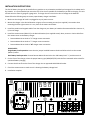
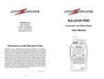
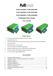
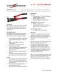
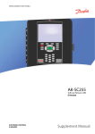
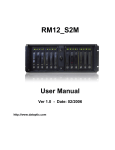
Emergency Vehicle Battery Charger
Model: EVC-45
Operation Manual
TABLE OF CONTENTS
General Information..................................................................................................................... Page 2
Features.................................................................................................................................... Page 2
Specifications............................................................................................................................ Page 2
Dual Cooling Fans..................................................................................................................... Page 2
Battery Selector Type Switch.................................................................................................... Page 2
Charger LED Indicator Lights..................................................................................................... Page 2
Installation Instructions...............................................................................................................
Page 3
Troubleshooting............................................................................................................................ Page 4
Battery Charger Status.............................................................................................................. Page 4
Remote Meter Status................................................................................................................ Page 4
Warranty Policy............................................................................................................................ Page 5
Powerwerx, Inc.
263 N Berry St
Brea, CA 92821
Phone: 714-674-0073
Fax: 714-674-4949
www.powerwerx.com
Revised: 04-19-2013
GENERAL INFORMATION
DUAL COOLING FANS
Powerwerx model EVC-45 is a new generation of battery
charger designed for installation in emergency and
specialty vehicles. It’s ultra low profile design allows this
charger to be installed in a variety of vehicle locations.
The EVC-45 battery charger features super energy
efficient design using only 6.1 amps (115VAC) input
while producing 40 amps @ 14VDC ouput at full output.
EVC-45 battery charger is designed to charge from one
to six (12V) batteries on most vehicles. Ultra quiet DC
output is ideal for todays vehicles with two-way radio’s,
mobile computers and other sensitive electronics. The
RM12-2 battery/charger meter is available to remotely
monitor your charger/battery status.
EVC-45 includes a twin fan design to maximize the life
of the internal components and to allow continuous
operation at full rating. The Charger uses dual fan design
that draws air through the front of the unit and exhaust
it out the rear to improve cooling. The fans operate at
low speed and will increase in speed whenever load and/
or ambient air temperature increases.
BATTERY SELECTOR TYPE SWITCH
For maximum battery charging, a user selectable battery
type switch is provided. Please move the rocker switch
to the type of battery or batteries you will be charging.
The Battery Type switch LED also shows the status of of
the charger output (see below). NOTE: When using more
than one battery, never mix battery types.
FEATURES
•
•
•
•
•
•
•
•
Auto AC Voltage Input (90~260VAC, 50/60 Hz)
Thermally Controlled Dual Cooling fan design
Ultra Clean DC Output protects electronics
Large DC Output connection-up to 4 ga wire
40 Amp maximum DC output
Smart 3 Stage Charging
Compact design only: 3”H x 6.75”W x 13”L
Charger LED Status Lights show:
oo AC Input Power ON
oo DC Power Output ON
oo Charging Status Fast or Float
CHARGER LED INDICATOR LIGHTS
There are four LED indicators on the front panel of the
EVC-45 charger.
• AC Input OK - Green LED, indicates AC voltage is
reaching the charger. If LED does not light up, replace
the glass fuse located under where the AC mains
cord is plugged in.
• DC Output OK - Green LED, indicates DC power being
produced by the charger
• METER Power OK - Green LED, indicates DC voltage
applied to Meter output terminal block. The meter
contacts have a maximum output of 12 amps.
SPECIFICATIONS
• Battery Type LED - Green or Amber, flashing LED
light shows the mode the charger is currently in
the FAST charging mode with DC output from 3-40
amps. Solid LED (non-flashing) the charger is now in
the “FLOAT” maintenance mode which is 2.0 amps
or less which maintains the battery after the fast
charging mode.
Input Voltage Range............... 90-260VAC (50/60 Hz)
Input Amps (max output)....... [email protected], [email protected]
EVC-45 Battery Charger DC Output Voltages:
• Lead Acid: 14.2V @ 50% Load, 13.4V @ 0.2A Load
• AGM Type:14.2V @ 50% Load, 13.4V @ 0.2ALoad
• GEL Type: 14.0V @ 50% Load, 13.6V @ 0.2A Load
3 Stage Automatic Charging Modes:
Bulk Phase / Absortion Phase / Float Phase
Temperature Ratings: -20C to +60C, Derate linerarly from
100% @ 50C to 60% @ 60C
AC Input Fuse Value.............. 8 amps/glass type
DC Output Fuse Value........... ATC-30, blade type (QTY-2)
Case Size.............................. 3 1/16”H x 6 3/4”W x 13”L
Weight................................. 6.9 lbs
Warranty............................. 3 Years
2
INSTALLATION INSTRUCTIONS
The EVC-45 battery charger can be installed in any position or any orientation provided you have good air circulation and a
dry location. It is recommended you mount the EVC-45 as close as possible to the batteries you will be charging. This unit
will take wire size from 12 gauge to 4 gauge wire. The larger the wire size the less loss of voltage to the batteries.
Please follow the following steps to ensure proper battery charger installation:
1. Make sure the charger AC cord is unplugged to any AC power sources.
2. Mount the charger in the desired location using up to four mounting screws (user supplied). Use caution when
mounting the front right screw as it is very close to the meter connections.
3. Install the positive and negative cables from the charger to your battery or batteries. Recommended wire sizes are: 4,
6, 8 or 10 Gauge.
4. Install the remote meter (RM12-2) in the desired location (user supplied screws). Next, connect a 3-wire cable from
the remote meter to the battery charger.
• Remote Meter #1 terminal to “+” charger meter connection
• Remote Meter #3 terminal to “-” charger meter connection
• Remote Meter #4 ternimal to “M” charger meter connection
PLEASE NOTE:
Single battery bank operation: Leave the wire jumper installed between the #1 and #2 terminals on the remote
(RM12-2) meter.
Dual battery bank operation: Connect Remote Meter #2 terminal to the 2nd battery bank “+” positive terminal.
5. On the front of the charger, select the proper battery type (AGM/WET/GEL) with the front mounted rocker switch for
optimized battery charging.
6. Connect the AC cord from the front of the charger into an approved 100V-260V AC outlet.
7. Check the remote meter to make sure it is showing the battery voltage level.
8. Installation complete
3
TROUBLESHOOTING
Problem
Solution
Charger - AC LED Light OFF
• Check that AC cord is plugged in
• Check / Replace glass type AC fuse if blown in front of charger
• Reset the AC outlet breaker or Reset the outlet “GFI” type plug
Charger - AC LED Light ON /
DC LED Light OFF & No DC Output
• Check / replace the (2) ATC-30 fuses located inside of charger
• Turn OFF AC Power for wait 5 minutes. Plug back into AC power
• Check charger rear fans for blockage / clean as needed
BATTERY CHARGER STATUS
Battery Type LED Light - Flashing
Normal “Bulk” or “Absortion” fast charging mode
Battery Type LED Light - Steady ON
Normal “Float” slow charging mode
REMOTE METER STATUS: (6) Green segments ON
Battery 95-100% fully charged (13.0 - 14.5V)
(4-5) Green segments ON
Battery 85-95% level (12.3 - 12.9 V)
(3) Yellow meter segments ON
Battery at 70-80% level - needs charging (12.2 - 12.0V)
(2) Red meter segments ON
Battery less than 70% level - needs charging (11.9 - 11.5V)
(2) Red meter segments flashing
Battery depleted - needs charging (11.4 - 10.5V)
No remote meter display
Battery is dead - needs charging (battery less than 10.5V)
(6) Red meter segments flashing
Input battery overcharging (15.5+ VDC)
Blue LED light ON
Battery charger in fast mode charging
Blue LED light OFF
Battery charger in float, slow charge mode
Remote Meter Flashing once every 2 sec
Meter in energy saving “Sleep Mode”
Battery charger or engine has been OFF for more than 60 hours
4
WARRANTY POLICY
Battery Chargers and remote meters (models: EVC45, EVC-25, RM12-2) manufactured by Powerwerx
are warranted to be free of defects of material or
workmanship for a (3) three year warranty period from
the date the equipment was shipped. Liability is limited
to repairing or replacing at our factory, without charge,
any parts or defects. Equipment is to be returned,
shipping charges prepaid and will be returned, after
repair, shipping charges paid.
Powerwerx assumes no liability for damages of any kind
to associated equipment arising from the installation
or use of Powerwerx products. The purchaser, by the
acceptance of the equipment, assumes all liability for any
damages which may result from its installation, use or
misuse, by the purchaser, his or its employees or others.
5