1
s
Preface, Contents
SIMATIC
Basics of the SNMP OPC server
1
PCS 7 Integration of the SNMP
OPC Server
2
Configuring the SNMP OPC
Server in the PCS 7 Environment
3
Process Control System PCS 7 Settings on a Switch Based on
Network Diagnostics with the the Example of an OSM / ESM
SNMP OPC Server
Function Manual
Diagnostics and Test Support
5
Important SNMP Variables
6
Glossary, Index
Edition 04/2004
C79000-G8976-C195
4
Safety Guidelines
This manual contains notices intended to ensure personal safety, as well as to protect the products and
connected equipment against damage. These notices are highlighted by the symbols shown below and
graded according to severity by the following texts:
!
Danger
!
Warning
!
Caution
indicates that death, severe personal injury or substantial property damage will result if proper
precautions are not taken.
indicates that death, severe personal injury or substantial property damage can result if proper
precautions are not taken.
indicates that minor personal injury can result if proper precautions are not taken.
Caution
indicates that property damage can result if proper precautions are not taken.
Notice
draws your attention to particularly important information on the product, handling the product, or to a
particular part of the documentation.
Qualified Personnel
Only qualified personnel should be allowed to install and work on this equipment. Qualified persons
are defined as persons who are authorized to commission, to ground and to tag circuits, equipment, and
systems in accordance with established safety practices and standards.
Correct Usage
Note the following:
!
Warning
This device and its components may only be used for the applications described in the catalog or the
technical description, and only in connection with devices or components from other manufacturers
which have been approved or recommended by Siemens.
This product can only function correctly and safely if it is transported, stored, set up, and installed
correctly, and operated and maintained as recommended.
Trademarks
SIMATIC®, SIMATIC HMI® and SIMATIC NET® are registered trademarks of SIEMENS AG.
Third parties using for their own purposes any other names in this document which refer to trademarks
might infringe upon the rights of the trademark owners.
Copyright © Siemens AG 2004 All rights reserved
Disclaimer of Liability
The reproduction, transmission or use of this document or its
contents is not permitted without express written authority.
Offenders will be liable for damages. All rights, including rights
created by patent grant or registration of a utility model or design,
are reserved.
We have checked the contents of this manual for agreement with
the hardware and software described. Since deviations cannot be
precluded entirely, we cannot guarantee full agreement. However,
the data in this manual are reviewed regularly and any necessary
corrections included in subsequent editions. Suggestions for
improvement are welcomed.
Siemens AG
Bereich Automation and Drives
Geschaeftsgebiet Industrial Automation Systems
Postfach 4848, D- 90327 Nuernberg
©Siemens AG 2004
Technical data subject to change.
Siemens Aktiengesellschaft
C79000-G8976-C195
Preface
Purpose of the Manual
This manual informs you of the basic functions and most important configurations
when using the SNMP OPC server with the process control system SIMATIC
PCS 7. The necessary steps in configuration in all required modules of the process
control system PCS 7 are introduced. You should pay particular attention to the
conditions that relate specifically to PCS 7 in Chapter 2.
If information relates directly to handling individual components, we will refer you to
the manuals of the products where you will find more detailed information.
Required Experience
To understand the manual, you require a working knowledge of automation
engineering and should be familiar with the basics of PCS 7. You also require
knowledge of working with computers or PC-type tools (for example programming
devices) with the Windows 2000 operating system.
The basics of working with PCS 7 are explained in the Configuration Manual and in
Getting Started.
Validity of the Manual
The manual is valid for the software package SIMATIC PCS 7 V6.0.
Process Control System PCS 7 Network Diagnostics with the SNMP OPC Server
C79000-G8976-C195
iii
Preface
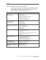
Further Documentation and Sources of Information
You will find further information on the topics of OPC and SNMP and on working
with the individual components in the following documentation and in the WinCC
Information System. The Manual CD "Process Control System PCS 7 V6.0,
Electronic Manuals also contains detailed information.
Manual
Content
Getting Started Process Control
System PCS 7;
Part 1 - Newcomers
Part 1:
Creating Projects
Working with the CFC Editor
Working with the Import/Export Assistant
Working with the SFC Editor
Compiling, Downloading and Testing
Working with the Operator Station
Configuration Manual Process
Control System PCS 7;
Engineering System
Basics of PCS 7
Creating Projects
Configuring Hardware
Configuring Networks
Configuration Manual Process
Control System PCS 7; Operator
Station.
Configuring SIMATIC Connections
Interconnecting OS Blocks
Configuring an Operator Station
Compiling an OS
Installation Guidelines
Configuration Manual WinCC
Getting Started
How WinCC Redundancy Works
User Archives
Creating a Sample Project "Project_Redundancy_Server"
Description of WinCC Projects
Server Project
Manual WinCC Hardware Options,
Part 3 Redundancy
Structure of a Redundant WinCC System
How WinCC Redundancy Works
Configuring the OS Server Pair
Guidelines for Setting Up a Redundant System
Entering the Servers in Windows 2000
Manual SIMATIC NET
Commissioning PC Stations
- Instructions and Quick Start
SIMATIC PC – Configuring Stations
SIMATIC NET Industrial Ethernet
OSM/ESM Network Management
User Manual
OSM/ESM Functions
iv
Configuring the OPC Server
SNMP Communication with OPC
Web Based Management
Process Control System PCS 7 Network Diagnostics with the SNMP OPC Server
C79000-G8976-C195
Preface
Guide to the Manual
This manual is divided into the following topics.
• Chapter 1 explains the basics of the SNMP OPC server.
• Chapter 2 describes the integration of the SNMP OPC servers in PCS 7.
• Chapter 3 describes the configurations of the various components of the SNMP
OPC server in PCS 7.
• Chapters 4 and 5 provide you with examples of settings on an OSM/ESM and
for testing and diagnostics.
• Chapter 6 lists the most commonly required Variables of the OSM/ESM family.
• The glossary contains terminology important for understanding this
documentation.
• The index helps you to locate text passages with important key words.
Process Control System PCS 7 Network Diagnostics with the SNMP OPC Server
C79000-G8976-C195
v
Preface
Further Support
If you have questions about the use of the products described in the manual, and
you cannot find the answers here, please contact your Siemens representative in
your local Siemens office.
You will find your contact person at:
http://www.siemens.com/automation/partner
Training Center
To familiarize you with the Process Control System SIMATIC PCS 7 and the S7
programmable controllers, we offer a range of courses. Please contact your
regional training center or the main training center in D 90327 Nuremberg.
vi
Phone:
+49 (911) 895-3200.
Internet:
http://www.sitrain.com
Process Control System PCS 7 Network Diagnostics with the SNMP OPC Server
C79000-G8976-C195
Preface
A&D Technical Support
Available at all times worldwide:
Nuernberg
Beijing
Peking
Johnson City
Worldwide (Nuernberg)
Technical Support
24 hours a day, 365 days a year
Phone:
+49 (180) 5050-222
Fax:
+49 (180) 5050-223
E-Mail:
adsupport@
siemens.com
GMT:
+1:00
Europe / Africa (Nuernberg)
United States (Johnson City)
Asia / Australia (Beijing)
Authorization
Technical Support and
Authorization
Technical Support and
Authorization
Local time: Mon.-Fri. 8:00 to 5:00 PM
Local time: Mon.-Fri. 8:00 to 5:00 PM
Local time: Mon.-Fri. 8:00 to 5:00 PM
Phone:
+49 (180) 5050-222
Phone:
+1 (423) 262 2522
Phone:
+86 10 64 75 75 75
Fax:
+49 (180) 5050-223
Fax:
+1 (423) 262 2289
Fax:
+86 10 64 74 74 74
E-Mail:
adsupport@
siemens.com
E-Mail:
simatic.hotline@
E-Mail:
adsupport.asia@
GMT:
+1:00
GMT:
-5:00
GMT:
+8:00
sea.siemens.com
siemens.com
The languages of the SIMATIC Hotlines and the authorization hotline are generally German and English.
Process Control System PCS 7 Network Diagnostics with the SNMP OPC Server
C79000-G8976-C195
vii
Preface
Service & Support on the Internet
In addition to our documentation services, you can also make use of all our
knowledge on the Internet.
www.siemens.de/snmp-opc-server
Here, you will find:
• The Newsletter that keeps you constantly up to date with the latest information
on the products you use.
• The documents you need using our Search engine in Service & Support.
• Examples and applications, in particular a complete WinCC example.
• A forum in which users and specialists exchange worldwide experience.
• Your local representative for Automation & Drives.
• Information on on-site service, repair and spares. You will find far more in
"Services".
viii
Process Control System PCS 7 Network Diagnostics with the SNMP OPC Server
C79000-G8976-C195
Contents
1
Basics of the SNMP OPC Server
1.1
1.2
2
3
Motivation for the Use of the SNMP OPC Server .............................................1-1
Functional Description of the SNMP OPC Server ............................................1-3
PCS 7 Integration of the SNMP OPC Server
2.1
2.2
2.3
2-1
Runtime Model ..................................................................................................2-1
Configuring ........................................................................................................2-3
Settings of the OS Server in the PCS 7 Environment.......................................2-4
Configuring the SNMP OPC Server in the PCS 7 Environment
3.1
3.2
1-1
3-1
HW Config Configuring in the PCS 7 Project....................................................3-1
WinCC Configuration ........................................................................................3-8
4
Settings on a Switch Based on the Example of an OSM / ESM
4-1
5
Diagnostics and Test Support
5-1
6
Important SNMP Variables
6-1
6.1
6.2
MIB II Standard Variables .................................................................................6-1
Other Variables of the OSM/ESM Family .........................................................6-5
Glossary
Index
Process Control System PCS 7 Network Diagnostics with the SNMP OPC Server
C79000-G8976-C195
ix
Contents
x
Process Control System PCS 7 Network Diagnostics with the SNMP OPC Server
C79000-G8976-C195
1
Basics of the SNMP OPC Server
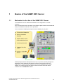
1.1
Motivation for the Use of the SNMP OPC Server
The SNMP OPC server makes data available for the diagnostics of TCP/IP
networks.
Errors and faults and even the failure of the Ethernet plant network can be detected
early and downtimes reduced or even prevented.
This increases the reliability and improves the availability of your plant.
SNMP (Simple Network Management Protocol) is a protocol specially designed to
administer TCP/IP networks and has been used for years in the IT world for
diagnostics in TCP/IP networks. Switches such as the OSM/ESM also support
SNMP. The network components and/or DTEs in Ethernet make their status
available with the SNMP OPC server.
Process Control System PCS 7 Network Diagnostics with the SNMP OPC Server
C79000-G8976-C195
1-1
Basics of the SNMP OPC Server
Apart from detailed diagnostics of SNMP-enabled devices, simple status
monitoring of IP devices can be integrated into your plant concept. This means that
in addition to the existing system and process diagnostics, diagnostics of the
complete IP network infrastructure can be integrated.
The visualization of this information (represented as information in topological
and/or table form) can be individually designed and adapted to the particular
requirements of the customer plant.
Apart from simple device diagnostics, detailed information such as the status
monitoring of redundant network structures (for example, an OSM ring) or port load
can be indicated depending on the user's requirements.
More detailed information (for example application samples, FAQs and white
paper) is available from the following Web site www.siemens.de/snmp-opc-server
1-2
Process Control System PCS 7 Network Diagnostics with the SNMP OPC Server
C79000-G8976-C195
Basics of the SNMP OPC Server
1.2
Functional Description of the SNMP OPC Server
Using the SNMP OPC server, SNMP-enabled network components and IP devices
such as the SIMATIC NET OSM / ESM can also be monitored in plants. The SNMP
OPC server adopts the role of translator of SNMP on the OPC interface of your
PCS 7 application. The device information can be read and to some extent also
written. This allows diagnostics of individual devices and even the complete
network infrastructure as well as the control (only with write access) of device
properties.
The SNMP OPC server also includes a MIB compiler with which other SNMPenabled devices can be integrated at a later time. Using the MIB compiler, existing
device profiles can be adapted and new device profiles created.
A device profile describes the range of variables of a device, for example OSM,
that can be mapped on the OPC server. Only variables included in the device
profile can be integrated in your application.
SIMATIC devices that have special SNMP agents, such as switches (OSM, ESM,
ELS) and Industrial Ethernet communications processors CP 1613 and the CPs
343-1 /443-1 are already included with their device profiles. Devices with an IP
address but without an SNMP agent can be monitored using the ping mechanism.
The user can add device information such as a contact person, location and device
description.
All SNMP-enabled devices provide a certain range of standardized and partly
device-specific variables (see Section 6) by means of an SNMP agent. The data
exchange between an SNMP client, for example the SNMP OPC server, and its
assigned agents (for example OSM) generally takes place within a certain cycle.
The range of variables and the cycle time is generally specified in the configuration.
The agents do, however, have the capability of reporting certain events such as the
failure of a port to the SNMP OPC server unsolicited using an SNMP trap.
Cyclically queried SNMP variables are accessible to the OPC client application (for
example PCS 7) over the OPC and Data Access interface. Acyclic data of the
network components resulting from SNMP traps are mapped both on the Data
Access and on the OPC Event interface. OPC client applications that do not yet
support the "Alarms and Events" OPC Standard can therefore also evaluate SNMP
traps.
Note
The use of SNMP traps or OPC events is optional. Generally, the information
transferred with traps is polled using SNMP get requests. As default, WinCC makes
OPC Data Access available for this.
Process Control System PCS 7 Network Diagnostics with the SNMP OPC Server
C79000-G8976-C195
1-3
Basics of the SNMP OPC Server
1-4
Process Control System PCS 7 Network Diagnostics with the SNMP OPC Server
C79000-G8976-C195
2
PCS 7 Integration of the SNMP OPC Server
The following information relates to OSM/ESM since these are the only devices
currently released for PCS 7 V6.0 SP3.
2.1
Runtime Model
The SNMP OPC server runs on an OS server. The SNMP interface is the interface
to the network. This is included in the standard components of Windows 2000. If
you only use OPC Data Access, no additional operating system functionality needs
to be installed.
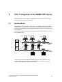
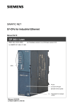
The following schematic shows the configuration of the SNMP OPC server on one
or more OS servers:
Clien
t
Clien
t
Clien
t
OSM
PCS7
OSM
OSM
WinCC
OSServe
r
OSServe
r
OPCServer
OSM
Terminal bus
TCP/IP
OSServe
r
OSM
OSM
OSM
d i
g
i
t a
Plant bus
ISO + TCP/IP
l
AS
d i
g
i
t
a l
AS
Communication with the SNMP-enabled devices is over IP and Ethernet. This
means that the devices must also be reachable over IP. This can be checked
quickly, for example with a "ping" from the server.
Process Control System PCS 7 Network Diagnostics with the SNMP OPC Server
C79000-G8976-C195
2-1
PCS 7 Integration of the SNMP OPC Server
The SNMP-enabled devices such as the OSM/ESM must be assigned an IP
address to use SNMP. This is possible with all devices using the following
mechanisms:
•
RS-232 terminal
•
BOOTP
and as of firmware version 2.3.0 also with
•
DHCP server
•
PST Tool (see download www4.ad.siemens.de/view/cs/en/14929629)
•
STEP7/NCM PC
When using the SNMP OPC server, make sure that the IP address configured in
PCS 7 and the existing online IP address match.
Note
To monitor the Ethernet switches OSM/ESM, the OS server on which the SNMP
OPC server runs must be capable of TCP/IP not only on the terminal bus but also
on the plant bus. Since the ISO protocol is used for communication on the network
adapter (for example CP 1613) of the plant bus in PCS 7 plants, a separate network
adapter must be planned on the OS for communication over the TCP/IP protocol on
the plant bus to avoid mixed operation of the network protocols on one adapter.
In total, the OS server therefore requires three network adapters: Apart from the
network adapter for the plant bus (for example a CP 1613), a network adapter for
TCP/IP communication on the terminal bus and a network adapter for monitoring
the OSM/ESM on the plant bus must be installed.
The interface of the SNMP OPC server to PCS 7 is the OPC client channel of the
WinCC data manager. The SNMP variables are therefore maintained in the data
management of the data manager and can be further processed with WinCC tools.
2-2
Process Control System PCS 7 Network Diagnostics with the SNMP OPC Server
C79000-G8976-C195
PCS 7 Integration of the SNMP OPC Server
2.2
Configuring
To use the SNMP OPC server in the PCS 7 runtime environment described above,
it must be configured in terms of the network configuration, device profile, and
WinCC integration in the engineering phase:
Initially, the IP addresses of the SNMP-enabled devices must be configured for the
SNMP OPC server with STEP7/NCM PC and the appropriate profile selected. The
device profile that describes the range of SNMP variables already exists for the
OSM/ESM in the configuration.
•
There is exactly one entry for each SNMP-enabled device (for example
OSM/ESM) in the properties dialog of the configuration of the SNMP OPC
server. The configured IP addresses must match those of the devices (see
Chapter 4).
•
A device profile is a table of variables that can, when necessary, be modified
with a MIB compiler or created individually for other devices.
The variables specified by means of the profile are available in the OPC client
application. Here, the required variables are included in the data management
WinCC in a further step. For each OPC item to be monitored, the user creates a
variable in the WinCC tag manager and, if required, creates control system
messages in WinCC Alarm Logging.
For further details of configuring the SNMP OPC server, refer to Chapter 3,
Configuring the SNMP OPC Server in PCS 7.
Process Control System PCS 7 Network Diagnostics with the SNMP OPC Server
C79000-G8976-C195
2-3
PCS 7 Integration of the SNMP OPC Server
2.3
Settings of the OS Server in the PCS 7 Environment
To be able to operate the OS server as an additional SNMP OPC server correctly
in the PCS 7 environment, special settings are necessary compared with the
configuration in the simple SIMATIC NET environment:
Since the ISO protocol is used for communication on the network adapter (for
example CP 1613) of the plant bus in PCS 7 plants, a separate network adapter
must be planned on the OS for communication over the TCP/IP protocol on the
plant bus to avoid mixed operation of the network protocols on one adapter. As a
result, a different TCP/IP network identifier must be set on the TCP/IP adapter of
the terminal bus compared with that on the TCP/IP adapter of the plant bus to
avoid address space overlaps on both TCP/IP adapters (for example 192.11.81.xxx
on the terminal bus and 142.11.81.xxx on the plant bus). After installing an
additional network adapter for communication between the SNMP OPC server and
the OSMs/ESMs connected to the plant bus, the following network settings must be
made on the OS server:
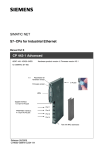
Step
Procedure
1
First activate the network connection:
2-4
Process Control System PCS 7 Network Diagnostics with the SNMP OPC Server
C79000-G8976-C195
PCS 7 Integration of the SNMP OPC Server
Step
Procedure
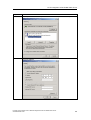
2
Set the protocols. Deactivate all protocols and services except for the TCP/IP protocol:
3
Set the IP address:
Process Control System PCS 7 Network Diagnostics with the SNMP OPC Server
C79000-G8976-C195
2-5
PCS 7 Integration of the SNMP OPC Server
Step
Procedure
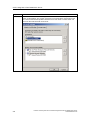
4
In the "Advanced -> Advanced Settings" menu in the Network and Dial-up Connections
dialog, set the bindings: The network connection for the terminal bus must be first in the
list to avoid communication problems between server and clients in runtime mode. No
"Client for Microsoft Networks" must be set:
2-6
Process Control System PCS 7 Network Diagnostics with the SNMP OPC Server
C79000-G8976-C195
3
Configuring the SNMP OPC Server in the
PCS 7 Environment
The following section describes the configuration of the SNMP OPC server in the
PCS 7 environment in greater detail, based on an example. The configuration work
is done on an engineering station (ES).
3.1
HW Config Configuring in the PCS 7 Project
To operate an SNMP OPC server on an OS server, the SIMATIC PC station of the
OS server must be configured in the PCS 7 project. Select an empty row in the
hardware configuration of the SIMATIC PC station and add the OPC server. You
will find the OPC server in the "Standard" profile under "SIMATIC PC Station –
OPC Server – SW V6.1...":
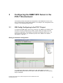
Editing the Hardware Configuration:
To configure the OPC server, double-click on the "OPC Server" row. The
properties dialog of the OPC server opens. Select the "SNMP" tab. The following
page is displayed:
Process Control System PCS 7 Network Diagnostics with the SNMP OPC Server
C79000-G8976-C195
3-1
Configuring the SNMP OPC Server in the PCS 7 Environment
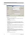
Editing Properties of the OPC Server:
If necessary, the cycle time can be changed in the first box. The cycle time
specifies the minimum time in which the variables of the SNMP OPC server can be
polled. With the "Access Protection" option, variable access can be controlled
(read, write).
Note
The cycle time specifies the interval at which the variables of the SNMP OPC server
are polled. To achieve good general performance in the PCS 7 project, this time
should not be selected unnecessarily shorter than the update time of the SNMP
variables configured on the OS. In general, the value "1000 ms" should be suitable
for most situations.
If you click on "Edit plant configuration ...", the SNMP-enabled devices to be
monitored are inserted and configured. The following screen appears:
3-2
Process Control System PCS 7 Network Diagnostics with the SNMP OPC Server
C79000-G8976-C195
Configuring the SNMP OPC Server in the PCS 7 Environment
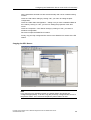
Editing the Plant Configuration:
Here, all the devices are made known to the SNMP OPC server.
(In this example, several entries have already been configured.)
By clicking on "Add...", a new node is added to the plant configuration. A new
dialog "Edit nodes" opens with default parameters.
By clicking on "Delete", the currently selected node is deleted from the plant
configuration.
If you click on "Edit...", you can modify the parameters of the currently selected
node. A new dialog "Edit nodes" opens with the current parameters.
As supplied today, the use of the SNMP OPC server on OSMs/ESMs is restricted.
The "Import Nodes" function is therefore currently not relevant and is reserved for a
later version in which the node list will be extended by all the devices in the current
project that have their own IP address.
If the device supports Web Based Management, clicking on "Web based
Management ..." opens the Internet Explorer with the corresponding URL.
For more detailed information on Web Based Management of the OSM/ESM, refer
to the OSM / ESM documentation. (SIMATIC NET Industrial Ethernet OSM/ESM
Network Management User Manual).
The "Edit nodes" dialog appears after you click on "Add..." or "Edit...".
Process Control System PCS 7 Network Diagnostics with the SNMP OPC Server
C79000-G8976-C195
3-3
Configuring the SNMP OPC Server in the PCS 7 Environment
Edit Nodes:
In this dialog box, you edit the following entries:
•
Name:
Enter a node name (for example Test_OSM_1) to identify the node uniquely
throughout the entire PCS 7 project.
•
IP address:
Enter the IP address of the device here.
•
Device profile:
Select a device profile. The device profile describes the mapping of SNMP
variables and traps on the OPC interface. With the "Create Profile..." button,
you can create your own profile from MIB files. The "Profil_OSM_V10.txt" profile
is recommended for this.
•
Community:
Enter the "SNMP community" of the device here. This is a type of password with
which it is possible to access the device (either read-only or read access).
•
Timeout:
Here you enter the maximum interval within which it is attempted to read a
value from the Microsoft stack before the quality of the variable is set to "bad"
on the OS.
•
Optimization of SNMP access
Select "Optimization" if you want several objects of the same type to be
requested in a frame to reduce network load. Do not select optimization if the
agent does not support this functionality. This saves the automatic initial query
and correction when the variable is registered.
•
Comment:
Enter any relevant text as the comment.
3-4
Process Control System PCS 7 Network Diagnostics with the SNMP OPC Server
C79000-G8976-C195
Configuring the SNMP OPC Server in the PCS 7 Environment
All the parameters entered here are stored internally and can be visualized during
runtime.
Close the "Edit nodes" dialog by clicking "OK"; you return to editing the plant
configuration.
Close the "Editor Plant Configuration..." dialog once you have created/modified all
the nodes by clicking on "OK"; you return to editing the properties of the OPC
server.
Close the "Properties – OPC Server" dialog by clicking on "OK"; you return to
hardware configuration.
Save and compile the SIMATIC PC station.
Finally, copy the fully configured OPC server to the SIMATIC PC station of the ES
station:
Copying the OPC Server:
Note
If you need to use a redundant system, the partner station should also be
configured appropriately. To do this, copy the previously configured OPC server to
the partner station. Then save and compile this partner station as well.
Process Control System PCS 7 Network Diagnostics with the SNMP OPC Server
C79000-G8976-C195
3-5
Configuring the SNMP OPC Server in the PCS 7 Environment
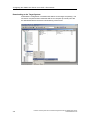
Downloading to the Target System:
Download the configuration of modified PC stations to the target computer(s). The
OS server computer and the redundant OS server computer (if it exists) can also
be downloaded before the actual commissioning of the server:
3-6
Process Control System PCS 7 Network Diagnostics with the SNMP OPC Server
C79000-G8976-C195
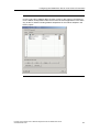
Configuring the SNMP OPC Server in the PCS 7 Environment
Note
In PCS 7 V6.0 SP3, SIMATIC NET CD V6.2 is used. In this case it is necessary to
run the Station Configuration Editor and to insert the same applications in the same
way as the PC station including address adaptation for the network adapter in the
PCS 7 project:
Process Control System PCS 7 Network Diagnostics with the SNMP OPC Server
C79000-G8976-C195
3-7
Configuring the SNMP OPC Server in the PCS 7 Environment
3.2
WinCC Configuration
To visualize the values provided by the SNMP OPC server on an OS server, the
WinCC tag management and the alarm system must be suitably configured. First
open the OS project in the PCS 7 project (WinCC application):
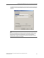
Expanding the WinCC Tag Management:
First expand the WinCC tag management with variables from the SNMP OPC
server. Then, when this is complete, configure the pictures and Alarm Logging. To
be able to create this configuration on the ES computer (required for PCS 7), the
SIMATIC PC station of the ES station must also be set up in the PCS 7 project as
an SNMP OPC server. This is achieved by copying the OPC server in the PC
configuration. Then download the configuration to the ES computer (see Section
4.1). Only then is it possible to create an OPC connection to the SIMATIC NET
OPC server on the local computer, and to insert the required variables into the
WinCC tag management using the tag browser.
Note
In a redundant OS server pair, there is only one ("master") OS project that needs to
be edited or configured. This OS project is automatically adapted (computer name,
redundancy settings,...) when you download to the redundant target computer.
3-8
Process Control System PCS 7 Network Diagnostics with the SNMP OPC Server
C79000-G8976-C195
Configuring the SNMP OPC Server in the PCS 7 Environment
To expand the WinCC tag management, first insert the OPC channel and the OPC
connection. You can do this by right-clicking on the OPC channel and selecting the
properties:
Note
Enter "OPC.SimaticNet" as the OPC server name. Specify only <LOCAL> as the
OPC server to access the local computer later. For a redundant server pair, the
actual computer name must not be entered here under any circumstances.
Otherwise, later in runtime, the standby server that has no OS project in its own
would access the master server remotely!
Process Control System PCS 7 Network Diagnostics with the SNMP OPC Server
C79000-G8976-C195
3-9
Configuring the SNMP OPC Server in the PCS 7 Environment
Now create the variables using the tag browser. You will find a list of suitable or
practical variables belonging to the OSM/ESM family along with a description in
Chapter 6.
Create a variable in the data manager for each OPC item to be monitored. In the
case of the OSM/ESM, the variables "&statepathval()" for connection monitoring
and "snOsmFaultState" for fault state monitoring are suitable because error
information compression can be used on the device with these variables. In the
simplest situation, create a variable in the data manager manually for each
OSM/ESM in the network:
3-10
Process Control System PCS 7 Network Diagnostics with the SNMP OPC Server
C79000-G8976-C195
Configuring the SNMP OPC Server in the PCS 7 Environment
Then adapt the data types of all variables that will be configured later in Alarm
Logging (for example ‚..._snOsmFaultState’), where necessary from signed to a
signed to allow bit-by-bit evaluation of the alarms in WinCC.
You do this with the "DwordToUnsignedDword" entry in the format adaptation for
the example of a 32-bit variable shown above.
Note
The messages or their numbers must not be located in the number range reserved
for system messages and AS messages !
When you have created all the variables, configure Alarm Logging as follows:
Process Control System PCS 7 Network Diagnostics with the SNMP OPC Server
C79000-G8976-C195
3-11
Configuring the SNMP OPC Server in the PCS 7 Environment
Configuring WinCC Alarm Logging
Configuring all the alarms with the data type adapted variables created in the tag
management. Assign suitable message texts for control system messages to
specific value changes of the variables or create the message texts manually.
These message texts then appear during runtime in WinCC Alarm Logging when
the corresponding value change occurs. The user on the OS then receives a
control system message automatically as soon as a value changes (for example
signaling contact signals fault).
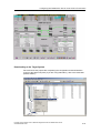
Configuring WinCC Pictures
Now configure the WinCC pictures and install them in the plant hierarchy (PH) in
the PCS 7 project or in the Picture Tree Manager (PTM) in the OS project as
required. The following schematic is an example of using the picture window
technique in runtime mode:
3-12
Process Control System PCS 7 Network Diagnostics with the SNMP OPC Server
C79000-G8976-C195
Configuring the SNMP OPC Server in the PCS 7 Environment
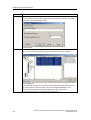
Downloading to the Target System
Save and close the project after completing the configuration and download the
project to the target computer (if you are using redundancy, also to the redundant
partner station):
Process Control System PCS 7 Network Diagnostics with the SNMP OPC Server
C79000-G8976-C195
3-13
Configuring the SNMP OPC Server in the PCS 7 Environment
3-14
Process Control System PCS 7 Network Diagnostics with the SNMP OPC Server
C79000-G8976-C195
4
Settings on a Switch Based on the
Example of an OSM / ESM
To access OSMs / ESMs over SNMP, they must be configured. The assignment of
an IP address is absolutely necessary. When using other devices, refer to the
product manual supplied. The following screenshot shows an example of a setting
for the IP address, subnet mask, and, if necessary, default gateway.
Note on Setting the Fault Mask:
In a ring structure, it is advisable not only to monitor the power supply is also ports
7 and 8. This allows a cable break in the ring to be detected. The changeover of the
redundancy manager to the active state, for example when there is a cable break in
the ring, does not necessarily lead to an OSM/ESM error state and corresponding
message if no additional messages from the redundancy manager status variables
are configured.
Process Control System PCS 7 Network Diagnostics with the SNMP OPC Server
C79000-G8976-C195
4-1
5
Diagnostics and Test Support
With the OPC Scout, you can establish a connection to the OPC server and test
your configuration without a client. The OPC Scout for browsing the mapped SNMP
information is supplied along with the SNMP OPC server.
The OPC Scout for Commissioning and Testing
You can access the objects of previously configured network components using
any OPC client. Follow the steps below to read or write objects with the OPC
Scout.
Step
Procedure
1
Start the OPC Scout:
.
Double-click on the entry "OPC.SimaticNET" to connect the OPC Scout with the OPC
server.
Process Control System PCS 7 Network Diagnostics with the SNMP OPC Server
C79000-G8976-C195
5-1
Diagnostics and Test Support
Step
Procedure
2
Enter a group name.
If you do not enter a group name, a group with the default name "~Group1" is created or
"Groupn" (n>1) if Group1 already exists.
Confirm with OK.
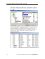
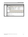
3
Double-click on the group entry you just created to open the OPC browser. In the left-hand
pane, you will see the hierarchically arranged name space of the OPC variables:
When you click on an element in the tree, the OPC items defined for the element appear
in the middle pane.
In the middle pane, select OPC items from the relevant branches and enter them in the
right-hand pane using the arrow button. The structure displayed depends on the
previously selected names (for example SNMP:[Test_OSM_1]sysContact).
Confirm the dialog with "OK" to enter the items in the group.
5-2
Process Control System PCS 7 Network Diagnostics with the SNMP OPC Server
C79000-G8976-C195
Diagnostics and Test Support
Step
Procedure
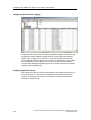
4
The table of the main window displays the selected variables with the following additional
information:
The current value of the item.
Access rights
Information on the integrity of the data
Time stamp
Process Control System PCS 7 Network Diagnostics with the SNMP OPC Server
C79000-G8976-C195
5-3
Diagnostics and Test Support
5-4
Process Control System PCS 7 Network Diagnostics with the SNMP OPC Server
C79000-G8976-C195
6
Important SNMP Variables
6.1
MIB II Standard Variables
Below, you will find a list with several SNMP variables from the MIB II range for
monitoring the device status. MIB II describes the range of SNMP variables that
are normally supported by SNMP-enabled devices.
For more detailed information on MIBs, refer to the following FAQ
Link : www4.ad.siemens.de/view/cs/en\15177711
Note:
The variables listed here are part of the existing profile "Profil_OSM_V10.txt" of
STEP 7/NCM PC. The variables from the "Interface" folder can be indexed
according to port (1 through n) . "ifDescr.2", for example, describes the name of
the second port.
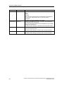
Table 1: Variables in the System Folder
Variable
Access rights
Description
sysDescr
Read-only
A string of up to 256 characters is used.
This value contains a vendor-specific identification of the device. An
OSM TP62 is identified here as "OSM TP62".
sysObjectID
Read-only
This displays the address (object identifier) at which the devicespecific SNMP variables can be accessed:
"1.3.6.1.4.1.4329.6.2.nnn.mmm"
If no private OIDs have yet been declared, the object identifier is
[0,0].
Here, the default value is 0.
sysUpTime
Read-only
Counter in hundredths of seconds since the last reset (for example
after power up).
This value is set by the system.
sysContact
Read and write
Here, the person responsible for the network can enter a contact
person. (Default: empty).
A string up to 256 characters long can be entered.
sysName
Read and write
Here, the network administrator can enter any name for the device.
Default: empty
A string up to 256 characters long can be entered.
Process Control System PCS 7 Network Diagnostics with the SNMP OPC Server
C79000-G8976-C195
6-1
Important SNMP Variables
Variable
Access rights
Description
sysLocation
Read and write
Here, the network administrator can enter the location of the device
Default: empty
A string up to 256 characters long can be entered.
sysService
Read-only
Displays the functions (services), that the component provides
according to the ISO/OSI model.
Layer functionality:
1. physical (for example repeater)
2. datalink/subnetwork (for example bridges, switches)
3. internet (for example IP gateways, router)
4. end to end (for example IP hosts)
5. applications (for example E-mail server)
The value is a 32-bit integer supplied by the system.
6-2
Process Control System PCS 7 Network Diagnostics with the SNMP OPC Server
C79000-G8976-C195
Important SNMP Variables
Table 2: Variables in the Interface Folder
Variable
Access rights
Description
ifNumber
Read-only
Number of different interfaces available in the component. For an
OSM with 8 ports, the number 8 is displayed.
The value is a 32-bit integer supplied by the system.
ifDescr
Read-only
This value includes the name and possibly further information about
the particular port.
Ethernet port of a CP 343-1 as an example:
SIEMENS SIMATIC NET CP343-1 6GK7343-1EX20-0XE0 HW:
Version 1 FW: Version 1.1.10 Fast Ethernet Port 1 Rack 0 Slot 4
A string of up to 256 characters is used.
ifType
Read-only
For SIMATIC NET, the value "ethernet-csmacd(6)" is entered.
Other possible values:
other(1), -- none of the following
regular1822(2),
hdh1822(§),
ddh-x25(4),
rfd977-x25(5),
ethernet-xsmacs(6),
iso88023-csmacd(7),
iso88024-tokenBus(8),
iso88025-tokenRing(9),
iso88026-man(10),
starLan(11),
proteon-10Mbit(12),
hyperchannel(14),
fddi(15),
lapb(16),
sdlc(17),
dsl(18), -- T-1
el(19), -- the European version of T-1
basicISDN(20),
primaryISDN(21), -- system serial interface
propPointToPointSerial(22),
ppp(23),
softwareLoopback(24),
con(25), -- CLNP over IP
ethernet-3Mbit(26),
nsip(27), -- KNS over IP
slip(28), -- generic SLIP
ultra(29), -- ULTRA Technologies
ds3(30), -- T-3
sip(31), -- SMDS
frame-relay(32)
The value is an integer supplied by the system.
ifSpeed
Read-only
Estimated value of the nominal bandwidth of the Ethernet port in bits
per second. In SIMATIC NET either 10 Mbps or 100 Mbps is
displayed.
The value is of the data type "Gauge".
Process Control System PCS 7 Network Diagnostics with the SNMP OPC Server
C79000-G8976-C195
6-3
Important SNMP Variables
Variable
Access rights
Description
ifOpenStatus
Read-only
Value from the list:
up(1),
down(2),
testing(3),
Here, the current operating state of the Ethernet port is displayed.
The "testing(3)" state indicates that no user data is being
transported.
ifLastChange
Read-only
The value is an integer supplied by the system.
Counter in hundredths of seconds. Counts how long the selected
port has been in the current state.
If the state was reached before the last reinitialization by the SNMP
manager, the value is zero.
The value is of the data type "TimeTicks" and is set by the system.
ifInErrors
Read-only
Counter of received packets not passed on to the higher protocol
layers due to detected errors.
The value is of the data type "Counter" and is set by the system.
ifOutErrors
Read-only
Counter for the packets not sent due to an error.
The value is of the data type "Counter" and is set by the system.
6-4
Process Control System PCS 7 Network Diagnostics with the SNMP OPC Server
C79000-G8976-C195
Important SNMP Variables
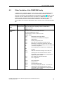
6.2
Other Variables of the OSM/ESM Family
In addition to the variables named in the previous sections, the OSM/ESM family
includes other important variables. You can insert these variables in the OPC
server or in the WinCC tag management as described in Chapter 3. Below, you will
find a list of these variables that can be queried by the SNMP OPC server when
used in a PCS 7 plant and can be made dynamic in the OS project. Apart from
these variables, there are numerous other variables in the device profile
"Profil_OSM_V10.txt" whose description can be read out of the corresponding MIB
file.
Variable
Access rights
Description
snOsmFault
State
Read and write
Shows the status of the signaling contact. Possible values:
Integer 1 = no error
Integer 2 = error.
snOsmFault
Value
Read and write
If an error occurs, this shows which error it is.
The 4-byte variable is bit-coded!
If all four bytes are set to 0, there is no error.
Possible values:
bit 0 =
Redundant power supply failed
bit 1 =
Connection to monitored port interrupted
bit 2 =
Internal error
bit 3 =
Standby configuration error
bit 4 =
More than one redundancy manager in ring
bit 5 =
Redundancy manager DIP switch was changed
with
As a result, the current operating state is inconsistent
the device configuration
The modified device configuration is adopted only
after
a restart
bit 6 =
current
STBY DIP switch was changed. As a result, the
operating state is inconsistent with the device
configuration. The modified device configuration is
adopted only after a restart.
bit 7 =
Error loading the firmware with NCM
bit 8 =
Port 1 segmented
...
bit 15 =
Port 8 segmented
bit 16 =
Observer error
bit 17 =
Unrecoverable ring error
bit 18=
current
The factory setting was restored. As a result, the
operating state is inconsistent with the device
configuration. The modified device configuration is
adopted only after a restart.
Process Control System PCS 7 Network Diagnostics with the SNMP OPC Server
C79000-G8976-C195
6-5
Important SNMP Variables
Variable
Access rights
snOsmRm
State
Read-only
Description
This shows whether the redundancy manager is active or passive.
Possible values:
snOsmRm
StateChanges
Read-only
snOsmStandB
yState
Read-only
Integer 1 =
Redundancy manager is passive. The OSM/ESM
is operating as the redundancy manager
and has opened the ring; in other words, the line of
OSMs/ESMs connected to it is working without
errors. The "passive" state is also displayed when
the redundancy manager - mode is disabled.
Integer 2 =
Redundancy manager is active. The OSM/ESM
is operating as the redundancy manager and has
closed the ring; in other words, the line of
OSMs/ESMs connected to it is interrupted (error).
The redundancy manager activates the connection
between the ring ports and therefore reestablishes
a functioning bus configuration
.
Shows how often the redundancy manager switched to active.
Possible values:
Counter (unsigned integer)
snOsmStandb Read-only
yStateChanges
This shows whether the standby status is active or passive.
Possible values:
Integer 1 =
The standby status of the OSM/ESM is passive; in
other words, it does not pass on any packets via
the standby ports.
Integer 2 =
The standby status of the OSM/ESM is active; in
other words, it passes on packets via the standby
ports.
Integer 10 =
Standby functionality is not supported
(only with mini switches).
Shows how often the standby status was active.
Possible values:
Counter (unsigned integer)
6-6
Process Control System PCS 7 Network Diagnostics with the SNMP OPC Server
C79000-G8976-C195
Glossary
Below, you will find explanations of important terminology that is necessary or
helpful in understanding this documentation.
10BASE-T
Standard for 10 Mbps Ethernet transmission on twisted pair cables
100BASET
Fast Ethernet Standard (100 Mbps) for data transmission on twisted pair cables
Automation system (programmable controller)
The automation system is made up of various hardware components and
integrated system functions depending on the target system. In PCS 7, the
components are as follows:
• Rack with 9 or 18 slots, also separate for redundant systems
• CPU 414-3, 416-2, 416-3 or 417-4 and the redundant CPU 414-4H and 417-4H
• Power supply 24 V DC or 120/230 V AC
• Work memory of 768 to 20 MB
• Memory card with 1 to 8 MB RAM
• Runtime license for the libraries, driver blocks / technological blocks
• Attachment to Industrial Ethernet for example CP 443-1
• Attachment to PROFIBUS as DP master or for S7 communication
IA
See Automation system
Bus
Common transmission path on which all nodes are connected; has two defined
ends.
CPU
Central Processing Unit = central module of the S7 automation system with control
unit and arithmetic logic unit, memory, operating system and interface for
programming device.
Process Control System PCS 7 Network Diagnostics with the SNMP OPC Server
C79000-G8976-C195
Glossary-1
Glossary
Diagnostics
Diagnostics is the detection, localization, classification, display, evaluation of
errors, faults and messages. Diagnostics provides monitoring functions that run
automatically during operation of the plant. This increases the availability of plants
by reducing the commissioning times and downtimes.
ESM
ESMs (Electrical Switch Modules) allow the structuring of switched networks with
100 Mbps. Electrical rings are set up with 2 twisted pair ports of the ESM. The data
rate in the ring is 100 Mbps; up to 50 ESMs can be used per ring.
Management level
The entire system used for automation consists of the management, process and
field levels. The management level is represented by PCs in the role of client,
multiclient and server with which the process can be operated and monitored.
Control system
A unit of components that can be used to monitor and control (open and closed
loop) industrial production.
MIB
Management Information Base. In network management, the database (tree
structure) in which all objects and variables that can be managed are entered.
MIB object
Management Information Base objects are the communication objects of SNMP.
They are made available by SNMP agents. Each SNMP-enabled device has an
SNMP agent.
OPC
OLE for Process Control is a world-wide communications standard for components
in automation. Based on Windows technology, OPC provides an open interface
that allows straightforward standardized data exchange between controllers,
operator control and monitoring systems and office applications of different vendors
OPC Scout
Tool for commissioning and testing the OPC SNMP server.
OSM
OSMs (Optical Switch Modules) allow the structuring of switched networks with 100
Mbps. OSMs with two fiber-optic ports are required to set up an optical ring. The
data rate in the ring is 100 Mbps; up to 50 OSMs can be used per ring.
Glossary-2
Process Control System PCS 7 Network Diagnostics with the SNMP OPC Server
C79000-G8976-C195
Glossary
Process level
The entire system used for automation consists of the management, process and
field levels. The process level is represented by automation systems (AS) and
interface modules.
Redundancy
Existence of more than one resource in a unit to perform a required function. In
automatic controls, these resources are generally a device or a software program.
Redundancy in PCS 7 means that a subsystem (master system) handles
processing of the process and the other subsystem (reserve system) operates as a
reserve in case the other system fails. Reserve does not, however, mean that this
subsystem has no function.
RFC
Request for Comment, standardization document of the research and development
group of the Internet, for example definition of protocols, procedures and services.
SNMP
Simple Network Management Protocol is a special protocol for administration of
TCP/IP networks. The individual nodes on the network (network components or
DTEs) have an SNMP agent that provides information in structured form.
SNMP OPC server
The SNMP OPC server makes data available for the administration of TCP/IP
networks of any OPC client systems.
SWITCH
Switches are connectivity devices that transfer data packets by evaluating the
source and destination addresses of incoming data packets and then forward the
data packets.
WinCC
The Windows Control Center is the process visualization system and the platform for IT and
business integration within the PCS 7 family.
Process Control System PCS 7 Network Diagnostics with the SNMP OPC Server
C79000-G8976-C195
Glossary-3
Glossary
Glossary-4
Process Control System PCS 7 Network Diagnostics with the SNMP OPC Server
C79000-G8976-C195
Index
B
Basics of the SNMP OPC server ................... 1-1
C
Configuring .................................................... 2-3
Configuring the SNMP OPC server
in the PCS 7 environment .......................... 3-1
Configuring WinCC Alarm Logging .............. 3-12
Configuring WinCC pictures......................... 3-12
D
Diagnostics and test support.......................... 5-1
E
Edit nodes...................................................... 3-4
Editing properties of the OPC server ............. 3-2
Editing the hardware configuration:................ 3-1
Editing the plant configuration........................ 3-3
Expanding the WinCC tag management........ 3-8
F
Functional description of the
SNMP OPC server..................................... 1-3
H
HW Config configuring in the PCS 7 project .. 3-1
I
Important SNMP variables..............................6-1
M
MIB II standard variables................................6-1
Motivation for the use of the
SNMP OPC server .....................................1-1
O
Other variables of the OSM/ESM family.........6-5
P
PCS 7 Integration of the SNMP OPC Server..2-1
R
Runtime model ...............................................2-1
S
Settings of the OS server in the PCS 7
environment................................................2-4
Settings on a switch based on the example
of an OSM / ESM .......................................4-1
W
WinCC configuration ......................................3-8
Process Control System PCS 7 Network Diagnostics with the SNMP OPC Server
C79000-G8976-C195
Index-1
Index
Index-2
Process Control System PCS 7 Network Diagnostics with the SNMP OPC Server
C79000-G8976-C195