1
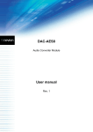
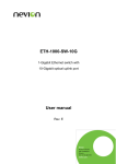
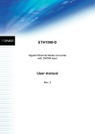
Flashlink User Manual WDM-C1xxx Flashlink CWDM Add & Drop Module network-electronics.com Rev. 3 WDM-C1xxx Rev. 3 Network Electronics ASA Thorøya P.O. Box 1020 Sandefjord, Norway Phone: +47 33 48 99 99 Fax: +47 33 48 99 98 E-mail: [email protected] www.network-electronics.com Service Phone: +47 90 60 99 99 Revision history Current revision of this document is the uppermost in the table below. Revision Replaces 3 2 1 0 2 1 0 - Date 2007-10-30 2007-10-17 23/01/06 02/01/04 Change description New front page and removed old logo. AS: Added Materials Declaration and EFUP RS: New WDM-C1xxx module, with new features. RS: Initial Revision 2 WDM-C1xxx Rev. 3 Contents Revision history............................................................................... 2 1 Product overview......................................................................... 4 2 Specifications .............................................................................. 5 2.1 Optical specifications...................................................................................5 2.2 Electrical specifications ................................................................................5 3 Configuration .............................................................................. 6 3.1 Mounting the module .................................................................................6 3.2 Applying signals to the module ...................................................................6 4 Module status.............................................................................. 8 5 Application examples .................................................................. 9 5.1 Single fibre CWDM add/drop multiplexer ...................................................9 5.2 CWDM add/drop multiplexers for a fibre pair..............................................9 5.3 All-optical SDI contribution network with CWDM add-drop multiplexing....9 6 Laser safety precautions ............................................................. 11 ® General environmental requirements for flashlink equipment ...... 12 Certificate of Conformity .............................................................. 13 Product Warranty ......................................................................... 14 Materials declaration and recycling information............................ 15 Materials declaration .................................................................... 15 Recycling information................................................................... 15 3 WDM-C1xxx Rev. 3 1 Product overview Figure 1: Block diagram of the CWDM add/drop module operation. The flashlink WDM-C1xxx is an all-optical CWDM add and drop multiplexer for a single CWDM channel. The unit is passive and there is no need for power or control. • The add and drop CWDM wavelength is chosen according to ITU-T G.694.2, with wavelengths from 1270 to 1610nm. Typical applications are single channel wavelength management in an optical ring structure. The content of a single CWDM wavelength can be replaced or re-generated at the ADMnodes throughout the ring giving increased flexibility in optical network design. A typical broadcast application can be a centralised studio with fibre connection to different local production facilities, each facility being assigned a dedicated wavelength. The received content is taken through the drop-port, whereas the transmitted content is passed to the ring via the add-port. 4 WDM-C1xxx Rev. 3 2 Specifications 2.1 Optical specifications Optical centre wavelengths: 1471, 1491, 1511, 1531, 1551, 1571, 1591 or 1611nm (red band) 1271, 1291, 1311, 1331, 1351, 1371, 1391 or 1411nm (blue band). Minimum 13nm. 1 add + 1 drop. Single Mode 9/125um. SC/UPC. Better than 40dB with Single Mode fibre. < 2.5dB incl. connectors (<2dB typical). Optical band pass: Channels: Transmission circuit fibre: Connector: Return loss: Insertion loss, passing wavelengths: Insertion loss, add or drop < 2.5dB incl. connectors (<2dB typical). channel: Isolation: − > 30dB (adjacent channel at drop port), − > 40dB (non-adjacent channel at drop port). Isolation, add channel: − > 50dB (add channel at drop port) − > 40dB (drop channel at out port). Directivity: > 50dB. Polarisation dependent < 0.2dB. loss: Maximum optical power: 250mW. Operating temperature: 0 – 70degC. 2.2 Electrical specifications Power: Control: None. None. 5 WDM-C1xxx Rev. 3 3 Configuration The WDM-C1xxx is a self-contained module that is mounted from the back of the flashlink frame, and fixed with 4 screws. Figure 2: Configuration of the connector module, ports 5-10 are not in use. 3.1 Mounting the module This section only applies if the module is not purchased pre-mounted in a subrack. In general we refer to the user manual for the sub-rack frame FR-2RU-10-2. This manual is also available from our web site: http://www.network-electronics.com/ No preparation is needed for the module itself. The blank in the corresponding position of the flashlink frame must be removed. The factory default position for this module is position 1 in the frame (the leftmost position as seen from the front). Slide the module carefully into position, make sure that the module enters both upper and lower guiding rails. Care should be taken to preserve the EMC-shielding at the connector module for this as well as for neighbouring modules. Fix the module with the 4 off M2.5x8 stainless steel screws enclosed and apply signals to the corresponding ports as described in section 3.2. 3.2 Applying signals to the module Signals are applied on a per wavelength basis. The term wavelength, refers to the add/drop wavelength for the respective module. 6 WDM-C1xxx Rev. 3 The input and output ports shown in figure 2 are the connections to the main fibre, to maintain traffic on the other wavelengths. The add port is used to feed the wavelength onto the main fibre, whereas the drop port is used to drop the wavelength content from the common fibre. The optical interface on the module is SC/PC, SC/SPC or SC/UPC connectors. 7 WDM-C1xxx Rev. 3 4 Module status The WDM-C1xxx is an all optical module with no electrical connections; hence there will be no on-board processing or monitoring. If the module is faulty this can be monitored on the receiver end. The only possibilities for the module to fail are if either one or more fibres are broken, or the fibre connections at the rear are bad. The WDM-C1xxx is an all optical module, so there are no LED's on the module. (Text not printed on the front panel). Figure 3: The WDM-C1xxx has no LED’s. 8 WDM-C1xxx Rev. 3 5 Application examples The WDM-C1xxx is the building block of all-optical photonic networks based on CWDM. We will in this chapter show some examples of how the module can be used. Since the module is all-optical; any signal format can be applied. 5.1 Single fibre CWDM add/drop multiplexer Having both add and drop functionality, the module can be used to add, drop or add and drop CWDM wavelengths on an optical fibre. This is shown in figure 4. Figure 4: Single fibre CWDM add/drop multiplexer 5.2 CWDM add/drop multiplexers for a fibre pair Dark fibre providers will normally provide a pair of fibres, in this case two modules are needed to give full add/drop functionality fibre pair. SDH/SONET traffic is bi-directional, using normally one fibre per direction. This is shown in figure 5. Figure 5: A CWDM add/drop multiplexer for a fibre pair consists of two modules 5.3 All-optical SDI contribution network with CWDM add-drop multiplexing This example describes how multiple WDM-C1xxx can be used to build a very efficient contribution network based on all-optical CWDM add-drop multiplexing. Up to 8 different sites are connected to a main studio, 3 of which are shown in figure 6. 9 WDM-C1xxx Rev. 3 Each site communicates with the main studio on a dedicated wavelength on the fibre. The site receives content from the main studio and transmits content to the main studio on the same wavelength, but in different directions on the fibre ring. The main studio has two 8-channel CWDM systems operating, one CWDM-8 to transmit e.g. SDI content to the sites, and another CWDM-8 to receive the SDI contribution signals from the different sites. On the electrical side, the control of the signals paths are taken care of by a VikinX router at each site and in the main studio (not shown in the figure). Note that the passing wavelengths will be attenuated by approx. 2.5dB through a module, so a power adjustment of the add wavelength can be necessary to avoid adjacent wavelength crosstalk. For longer signal paths, the optical transmission budget can be extended by a full 3R-regeneration performed by the MR-TR, SDI-TR or MR-TR-2,5G cards. Figure 6: Broadcast contribution network based on CWDM with add/drop multiplexing of single wavelengths throughout the network Being the building block of all-optical photonic networks, means that the WDM-C1xxx can be used in a variety of applications. 10 WDM-C1xxx Rev. 3 6 Laser safety precautions Guidelines to limit hazards from laser exposure. All the available EO units in the flashlink® range include a laser. Therefore this note on laser safety should be read thoroughly. The lasers emit light at 1270 nm or 1620 nm. This means that the human eye cannot see the beam, and the blink reflex cannot protect the eye. (The human eye can see light between 400 nm to 700 nm). A laser beam can be harmful to the human eye (depending on laser power and exposure time), therefore: Note! BE CAREFUL WHEN CONNECTING / DISCONNECTING FIBRE PIGTAILS (ENDS). NEVER LOOK DIRECTLY INTO THE PIGTAIL OF THE LASER/FIBRE. NEVER USE MICROSCOPES, MAGNIFYING GLASSES OR EYE LOUPES TO LOOK INTO A FIBRE END. USE LASER SAFETY GOGGLES BLOCKING LIGHT AT 1310 nm AND AT 1550 nm. Instruments exist to verify light output power: Power meters, IR-cards etc. Flashlink® features: The FR-2RU-10-2 is classified as Class 1 laser product according to EN 60 825-1:94/A11:96, and CFR Ch1(1997) Part 1040.10. If the front panel is removed, the FR-2RU-10-2 is classified as Class 1 laser product according to EN 60 825-1:94/A11:96, and class IIIb according to CFR Ch1(1997) Part 1040.10. Maximum output power: 5 mW. Operating wavelengths: >1270 nm. < 5mW >1270nm 11 WDM-C1xxx Rev. 3 ® General environmental requirements for flashlink equipment 1. The equipment will meet the guaranteed performance specification under the following environmental conditions: - Operating room temperature range: 0°C to 50°C - Operating relative humidity range: < 90% (non-condensing) 2. The equipment will operate without damage under the following environmental conditions: - Temperature range: -10°C to 55°C - Relative humidity range: < 95% (non-condensing) 3. Electromagnetic compatibility conditions: - Emissions: EN 55103-1 (Directive 89/336/EEC) - Immunity: EN 55103-2 (Directive 89/336/EEC) 12 WDM-C1xxx Rev. 3 Certificate of Conformity Network Electronics ASA N-3204 Sandefjord Norway Company Registration Number: NO 976 584 201 MVA Declares under sole responsibility that the product: Product Name: WDM-C1xxx Product Description: flashlink® CWDM add & drop module To which this declaration relates are of Norwegian origin and are in conformity with the following standards: EN 55103-1: 1996 Generic Emissions Standard EN 55103-2: 1996 Generic Immunity Standard 13 WDM-C1xxx Rev. 3 Product Warranty The warranty terms and conditions for the product(s) covered by this manual follow the General Sales Conditions by Network Electronics ASA. These conditions are available on the company web site of Network Electronics ASA: www.network-electronics.com 14 WDM-C1xxx Rev. 3 Materials declaration and recycling information Materials declaration For product sold into China after 1st March 2007, we comply with the “Administrative Measure on the Control of Pollution by Electronic Information Products”. In the first stage of this legislation, content of six hazardous materials has to be declared. The table below shows the required information. Toxic or hazardous substances and elements 組成名稱 Part Name WDM-C1xxx 鉛 汞 镉 六价铬 多溴联苯 多溴二苯醚 Lead Mercury Cadmium Hexavalent Polybrominated Polybrominated (Pb) (Hg) (Cd) Chromium biphenyls diphenyl ethers (Cr(VI)) (PBB) (PBDE) 0 O O O O O O: Indicates that this toxic or hazardous substance contained in all of the homogeneous materials for this part is below the limit requirement in SJ/T11363-2006. X: Indicates that this toxic or hazardous substance contained in at least one of the homogeneous materials used for this part is above the limit requirement in SJ/T11363-2006. This is indicated by the product marking: Recycling information Network Electronics provides assistance to customers and recyclers through our web site http://www.network-electronics.com. Please contact Network Electronics’ Customer Support for assistance with recycling if this site does not show the information you require. Where it is not possible to return the product to Network Electronics or its agents for recycling, the following general information may be of assistance: Before attempting disassembly, ensure the product is completely disconnected from power and signal connections. All major parts are marked or labelled to show their material content. Depending on the date of manufacture, this product may contain lead in solder. Some circuit boards may contain battery-backed memory devices. 15