1
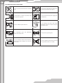
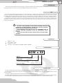
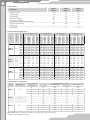
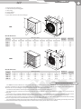
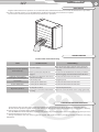
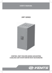
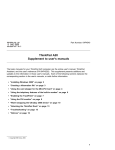
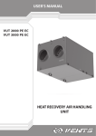
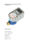
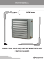
USER’S MANUAL
AOW Series
AIR HEATING (COOLING) UNIT WITH WATER-TO-AIR
HEAT EXCHANGER
2
CONTENT
Safety requirements
Introduction
Use
Delivery set
Designation key
Technical data
Design and operating logic
Mounting and set-up
Connection to power mains
Connection to power mains
Maintenance
Troubleshooting
Storage and transportation rules
Manufacturer's warranty
Acceptance certificate
Seller's information
Mounting certificate
Warranty card
3
5
5
5
5
5
7
8
10
10
11
11
11
12
13
13
13
14
AOW
3
SAFETY REQUIREMENTS
•
•
•
•
•
•
Read the user’s manual carefully prior to the operation and installation of the unit.
Installation and operation of the unit shall be performed in accordance with the present user’s manual as well as the provisions
of all the applicable local and national construction, electrical and technical codes and standards.
The warnings contained in the user’s manual must be considered most seriously since they contain vital personal safety
information.
Failure to follow the safety regulations may result in an injury or unit damage.
Read the manual carefully and keep it as long as you use the unit.
While transferring the unit control the user’s manual must be turned over to the receiving operator.
Symbol legend used in the manual:
WARNING!
DO NOT!
UNIT MOUNTING SAFETY PRECAUTIONS
The unit must be disconnected from the power
supply prior to every installation or repair
operation.
The unit must not be operated outside
the temperature range stated in the user's
manual or in aggressive or explosive
environments.
Do not install heating equipment or any other
equipment close to the unit cable.
Do not use damaged equipment or
conductors to connect the unit to power
mains.
While installing the unit follow the safety
regulations specific to the use of electric tools.
Unpack the unit with care.
Do not change the power cord length at your
own discretion. Do not bend the power cord.
Avoid damaging the power cord.
Use the unit as intended only.
4
UNIT OPERATION SAFETY PRECAUTIONS
Do not carry out the unit maintenance with wet
hands.
Do not wash the unit with water. Protect the
unit electric parts from water ingress.
ON
Do not block the air intake and exhaust vents
during the unit operation.
Disconnect the unit from power supply prior
to maintenance.
OFF
Do not let children operate the unit.
Do not damage the power cable while
operating the unit. Do not put any objects
on the power cable.
Keep combustible gases and inflammable
products away of the unit.
Do not open the operating unit.
In case of unusual sounds, smoke disconnect
the unit from power supply and contact the
service centre.
Do not let air flow from the unit be directed
to the open flame devices or candles.
AOW
5
INTRODUCTION
This user’s manual includes technical description, operation, installation and mounting guidelines, technical data for the air heating
(cooling) unit with water-to-air heat exchanger AOW, hereinafter referred as the unit.
USE
The air heating (cooling) units with water-to-air heat exchanger are designed for indoor air heating with the water-to-air heat
exchanger and uniform air distribution with the fan and louvre shutters. The integrated high-efficient electric heater and a powerful
fan enable quick air heating (cooling) in large premises or a local heating or cooling of a working space in hangars or industrial facilities.
The AOW unit is designed for air heating or cooling large industrial premises. Further application areas include workshops, garages,
car showrooms, stock houses, trade facilities, super- and hypermarkets, shops, sport halls, conference halls, poultry and cattle farms,
greenhouses and other similar premises. The unit design enables quick and easy mounting and reduces total investment costs for
heating (cooling) system.
THE UNIT IS NOT INTENDED TO BE USED BY CHILDREN, PHYSICALLY
OR MENTALLY DISABLED PERSONS, PERSONS WITH SENSORY DISORDER,
PERSONS WITH NO APPROPRIATE QUALIFICATION.
ANY OPERATIONS WITH THE UNIT MUST BE PERFORMED ONLY BY
PROPERLY QUALIFIED PERSONNEL AFTER THE APPROPRIATE SAFETY
BRIEFING.
THE UNIT INSTALLATION SITES MUST PREVENT ACCESS BY UNATTENDED
CHILDREN.
DELIVERY SET
AOW unit - 1 item
user’s manual - 1 item
packing box - 1 item
drain pipe - 1 item (applicable for AOW 25, AOW 30, AOW 45)
DESIGNATION KEY
AOW x ХХ
Unit type
АОW - air heating (cooling) unit
Modification
_ - model used both for cooling and heating
1 - model used for heating only
Heater power [kW]
TECHNICAL DATA
The unit is designed for indoor application with the ambient temperature ranging from +1 °C up to +50 °C.
The maximum permissible water temperature at 100 °C is 1.6 Map (16 bar). The unit is designed for application in moderate and cold
climate conditions.
The water is supplied to the water-to-air heat exchanger via a double-pipe system.
The water supplied to the water-to-air heat exchanger has low temperature in the warm season and high temperature during heating.
The unit design is regularly being improved, so some models can slightlyUnit
differtype
from those ones described in this manual.
6
Technical data:
АОW 25
АОW1 25
АОW 30
АОW1 30
АОW 45
АОW1 45
Voltage, 50 Hz [V]
230
230
230
Fan power [W]
136
191
255
Fan current [A]
0,6
0,85
1,12
Rotation speed [min -1]
1350
1440
1360
Noise level, 3 m [dB(A)]
53
55
58
Parameters
Maximum heat medium temperature [°C]
100
100
100
Ingress Protection Rating
IP 44
IP 44
IP 44
Insulation class
F
B
F
Air throw [m]
9
12
16
Inlet
temperature
[°C]
Water flow [l/s]
Water pressure
loss [kPa]
Power [kW]
Inlet
temperature
[°C]
Water flow [l/s]
Water pressure
loss [kPa]
Power [kW]
Inlet
temperature
[°C]
Water flow [l/s]
Water pressure
loss [kPa]
3850
Power [kW]
АОW 45
АОW1 45
Temperature difference
60/40 оС
Water pressure
loss [kPa]
3000
Temperature difference
70/50 оС
Water flow [l/s]
АОW 30
АОW1 30
Temperature difference
80/60 оС
Inlet
temperature
[°C]
2200
-15
-10
-5
0
5
10
15
-15
-10
-5
0
5
10
15
-15
-10
-5
0
5
10
15
Temperature difference 90/70
°C
Power [kW]
АОW 25
АОW1 25
Inlet air temperature
[°C]
Air flow [m3/h]
Model
Technical data for heating mode:
34,5
32,0
30,0
28,0
26,2
24,2
22,1
48,4
45,4
42,4
39,5
36,7
33,8
31,0
63,0
59,2
55,4
51,6
47,9
44,3
40,6
26,0
29,0
32,0
35,0
38,5
41,4
44,2
27,2
30,3
33,4
36,4
39,4
42,1
44,9
28,4
31,5
34,6
37,5
40,4
43,2
45,9
1,5
1,4
1,3
1,2
1,2
1,1
1,0
2,1
2,0
1,9
1,7
1,6
1,5
1,4
2,8
2,6
2,4
2,3
2,1
2,0
1,8
7,5
6,6
5,8
5,2
4,5
3,9
3,3
7,4
6,6
5,9
5,2
4,5
3,9
3,3
11,9
10,6
9,4
8,3
7,3
6,3
5,4
30,4
28,3
26,2
24,1
22,1
20,1
18,1
42,0
39,0
36,7
33,8
30,9
28,1
25,3
55,6
51,8
48,0
44,3
40,6
37,0
33,4
21,2
24,3
27,4
30,4
33,3
36,1
38,8
22,0
25,2
28,2
31,1
34,0
36,7
40,0
23,3
26,4
29,3
32,2
35,0
37,8
40,4
1,3
1,2
1,2
1,1
1,0
0,9
0,9
1,9
1,7
1,6
1,5
1,4
1,2
1,1
2,4
2,3
2,1
2,0
1,8
1,6
1,5
6,0
5,3
4,6
4,0
3,3
2,8
2,3
6,0
5,3
4,6
3,9
3,4
2,8
2,3
9,7
8,5
7,4
6,4
5,5
4,6
3,8
26,0
24,0
22,0
20,0
18,0
15,9
13,8
36,6
33,7
30,0
28,0
25,0
22,0
19,4
48,1
44,3
40,6
36,9
33,2
29,6
26,0
16,0
19,2
22,0
25,0
28,0
30,6
33,0
17,0
20,0
22,9
25,7
28,5
31,1
33,7
18,1
21,1
23,9
26,8
29,5
32,2
34,8
1,1
1,1
1,0
0,9
0,8
0,7
0,6
1,6
1,5
1,4
1,2
1,1
1,0
0,9
2,1
1,9
1,8
1,6
1,5
1,3
1,1
4,6
4,0
3,4
2,8
2,3
1,9
1,4
4,7
4,0
3,4
2,9
2,4
1,9
1,5
7,6
6,6
5,6
4,7
3,9
3,2
2,5
22,0
20,0
18,0
16,0
14,0
12,0
9,0
31,0
27,6
24,0
21,0
19,0
16,0
13,0
40,4
36,7
32,9
29,2
25,6
21,9
18,1
11,0
14,0
17,0
20,0
22,0
25,0
27,0
11,7
14,6
17,4
20,0
22,7
25,2
27,5
12,8
15,7
18,5
21,3
23,9
26,4
28,8
1,0
0,9
0,8
0,7
0,6
0,5
0,4
1,3
1,2
1,1
1,0
0,8
0,7
0,6
1,8
1,6
1,4
1,3
1,1
1,0
0,8
3,4
2,8
2,3
1,8
1,4
1,0
0,7
3,5
2,9
2,4
1,9
1,5
1,1
0,7
5,7
4,8
3,9
3,2
2,5
1,9
1,3
Technical data for cooling mode:
Model
АОW 25
АОW 30
АОW 45
Air flow [m3/h]
2200
3000
3850
Temperature difference 7/12 оС
Inlet temperature
Water flow [l/s]
[°C]
Inlet air temperature
[°C]
Power [kW]
35
9,1
26,0
1,6
7,5
30
5,8
22,5
1,0
6,1
25
3,2
21,0
0,6
2,1
20
2,0
18,0
0,3
0,9
35
11,4
27,0
2,0
11,2
30
7,3
22,9
1,3
5,0
25
3,9
21,1
0,7
1,6
20
2,4
17,7
0,4
0,7
35
18,0
24,9
3,1
31,8
Water pressure loss
[kPa]
30
10,8
21,7
1,9
12,9
25
7,3
19,0
1,3
6,3
20
3,2
17,4
0,5
1,4
Note: AOW1 model is designed for operation in heating mode only. The unit has no
components for condensate drainage.
AOW
7
1 - water-to-air heat exchanger
2 - axial fan with a protecting grille
3 - unit casing
4 - louvre shutters
5 - terminal box
6 - pipes of the water-to-air heat exchanger
2
3
L1
L
6
K
H
5
H1
АОW
43
4
B
B1
1
Overall dimensions:
Model
АОW 25
Dimensions [mm]
B
B1
H
H1
L
L1
K
Number of
coil rows
Weight [kg]
680
785
605
468
360
286
G 3/4”
2
37,0
АОW 30
680
785
655
518
360
286
G 3/4”
2
40,0
АОW 45
780
885
710
570
380
300
G 3/4”
2
50,0
2
3
L1
L
6
K
H
5
H1
АОW1
43
4
B
1
B1
Overall dimensions:
Dimensions [mm]
B
B1
H
H1
L
L1
K
Number of
coil rows
Weight [kg]
АОW1 25
630
690
555
468
320
262
G 3/4”
2
28,0
АОW1 30
630
690
605
518
355
262
G 3/4”
2
31,0
АОW1 45
730
790
655
570
380
285
G 3/4”
2
41,0
Model
DESIGN AND OPERATION LOGIC
The AOW unit consists of four basic components (refer fig. 1): a water-to-air heat exchanger (1), an axial fan with a protecting grille (2),
a polymer coated steel casing (3), louvre shutters (4). The water-to-air heat exchanger is made of copper tubing ribbed with aluminium.
The water-to-air heat exchanger is equipped with internally threaded (3/4) copper tubes.
An axial fan located at the unit inlet generates air flow in the water-to-air heat exchanger.
The protecting grille of the fan prevents foreign objects ingress inside the unit. The adjustable louvre shutters are located on the air
supply side.
Each louvre vane is manually adjustable which makes it easy to create a required air stream direction. The curved profile of the louvre
vanes prevents air flow turbulence and its rising toward upper part of the room thus keeping warm air within the heated area.
The unit operation is based on heat/cool conduction from the hot or cold water to surface of the copper tubes filled with circulating
water. The copper tubes have aluminium fins for extra large heat exchange surface.
The copper tubes transfer heat energy to the aluminium fins and the fins transfer it further to the air flow generated by the fan. The
heated (cooled) air flow is supplied to the premises and directed locally by means of the louvre shutters.
8
The AOW model is a single-room air heating / cooling system and the AOW1 model is a single-room air heating system.
The unit is suitable both for vertical and horizontal installation.
During operation of the unit in the cooling mode some condensate may appear on the surface of the heat exchanging surface and
get accumulated in the unit drain pan.
The AOW 25, AOW 30 and AOW 45 units must be equipped with a drain pipe. Fix the drain pipe to the unit bottom with rivets.
The drain pipe and the rivets are supplied with the air heating (cooling) unit.
Installation of the drain pipe:
The drain pipe opening is
plugged.
Remove the plug.
Apply some sealant on the mating surfaces of the pipe and drain
pan mating surfaces. Fix the pipe with fasteners.
The unit is designed for indoor installation in compliance with applicable hygienic norms and standards.
MOUNTING AND SET-UP
Provide free air access to the fan intake vent while installing the unit. The minimum distance between the wall or ceiling and the AOW
unit is 300 mm. The unit mounting location must provide free service access to the unit.
The unit is designed for wall mounting or any other vertical installation as well as ceiling mounting using the fixing brackets.
While connecting the water-to-air heat exchanger to the water main disable any loads that can damage the unit or tight connections.
Layout of the heat medium piping must ensure quick detachment for easy servicing and repair operations. Install a mud filter at the
heat medium inlet to the heat exchanger.
THE UNIT INSTALLATION SHALL ONLY BE PERFORMED BY PROFESSIONALS AFTER
CAREFUL STUDY OF THE PRESENT USER’S MANUAL.
WARNING!
FAILURE TO PROVIDE MINIMUM DISTANCE TO WALLS OR CEILING WILL IMPAIR THE UNIT
AERODYNAMIC AND THERMAL PROPERTIES AND SERICE LIFE OF THE UNIT.
AOW
9
Mounting accessories:
Model
Mounting angles
Mounting bracket
Multi-angle bracket
АОW 25
MKP-АОW
МК-АОW 25
МКУ-АОW 25
АОW 30
MKP-АОW
МК-АОW 30
МКУ-АОW 30
АОW 45
MKP-АОW
МК-АОW 45
МКУ-АОW 45
АОW1 25
MKP-АОW
МК-АОW1 25
МКУ-АОW1 25
АОW1 30
MKP-АОW
МК-АОW 25*
МКУ-АОW 25
АОW1 45
MKP-АОW
МК-АОW 30*
МКУ-АОW 30
* The cross pieces between the MK-AOW mounting brackets are not applicable in case of AOW1 mounting.
INSTALLATION OF THE UNIT WITH MKP-AOW MOUNTING SET
The MKP-AOW mounting set is used for ceiling mounting of the unit by means of the mounting studs or chains. Not included in the
delivery set, available as a special accessory.
Mounting stud
min 300 mm
INSTALLATION OF THE UNIT WITH
MKP-AOW
INSTALLATION OF THE UNIT WITH MKP-AOW MOUNTING BRACKET
min 300 mm
min 300 mm
The MK-AOW mounting bracket is used for ceiling or wall mounting of the unit. Not included in the delivery set, available as a special
accessory.
CEILING MOUNTING WITH MK-AOW
АОW
АОW1
WALL MOUNTING WITH MK-AOW
INSTALLATION OF THE UNIT WITH MKU-AOW MULTI-ANGLE BRACKET
The MKU-AOW mounting multi-angle bracket is used for ceiling or wall mounting of the unit. Not included in the delivery set,
available as a special accessory.
MKU-AOW design enables installation of the unit to the wall or ceiling and fixation at 30° and 45°.
RIGHT ANGLE MOUNTING WITH
MKU-AOW
30° MOUNTING WITH
MKU-AOW
30°
45° MOUNTING WITH
MKU-AOW
45°
10
UNIT REACH DISTANCE
Failure to provide the minimum distance to walls or ceiling 0.3 m will impair the unit aerodynamic and thermal properties and service
life of the unit.
Ceiling mounting:
Minimum distance to the ceiling is 0.3 m
Mounting height is 4 to 14 m
3-8 m
4-14 m
Wall mounting:
Minimum distance to the wall is 0.3 m
Mounting height is 3 to 8 m
Max. air throw is 16 m
16
16 m
m
WIRING DIAGRAM
DISCONNECT THE UNIT FROM POWER MAINS PRIOR TO ANY ELECTRIC INSTALLATION OPERATIONS. THE UNIT
ELECTRICAL INSTALLATION SHALL ONLY BE PERFORMED BY A PROFESSIONAL ELECTRICIAN. THE RATED ELECTRICAL
PARAMETERS OF THE UNIT ARE STATED ON THE RATING PLATE. ANY TAMPERING WITH THE INTERNAL CONNECTIONS IS
PROHIBITED AND WILL VOID THE WARRANTY.
The unit is rated for connection to single-phase ac 220-230 V / 50 Hz power mains.
For unit electric connections use insulated, durable and heat-resistant cables and wires with a cross section not below 0.5 mm2.
The wire sections as stated are for reference only! The actual selection should be made in consideration of the maximum wire
temperature depending on the wire and insulation type, the maximum current, the lead wire length and its installation (suspended,
duct-mounted or wall-mounted).
Connect the unit to power mains through the terminal block located inside the terminal box in compliance with the wiring diagram
and the terminal designation.
The automatic circuit breaker with thermomagnetic release (automatic switch)
must be installed at the input to break all the circuits.
The circuit breaker QF must be installed in such a way as to provide a free access
for quick shutdown of the unit.
The trip current must be in compliance with the current consumption of the unit.
The rated recommended current of the switch is 1.6 A.
The unit is equipped with AC external rotor motors with self-resetting integrated
overheating protection.
WIRING DIAGRAM
L
~230 V
50 Hz
QF
X1
L
N
PE
1
2
N
3
РЕ
4
CONTROL AND ADJUSTMENT
Smooth or step fan speed control is performed by means of a thyristor or transformer speed controller. Reducing the fan speed enables
to reduce air flow and heating or cooling heat exchange.
The air heating (cooling) unit is operated via the UWT-1E control unit (special accessory). The control unit has three operation modes and
three fan speed stages for AOW.
The control unit is equipped with an on/off switch with a control lamp, cable glands for cable connections and a thermal fuse for short
circuit protection.
The control unit is designed for joint operation with the TST-1-300 digital thermostats with sensor display (TSTD-1-300 is available
with a remote control) or RTS-1-400 with a LCD display (RTSD-1-400 is available with a remote control). The thermostats are available as
special accessories. The thermostat must be installed in a premise that is heated or cooled by the AOW unit. The thermostat is used for air
temperature monitoring and operation mode control.
The thermostat installation place must not be subjected to temperature fluctuations induced by open windows, door and heating
devices. Several air heating (cooling) units installed in the same premise may share one thermostat.
AOW
11
MAINTENANCE
Regular routine maintenance operations are recommended. The aluminium ribs must be cleaned of dirt and dust once a year with a
wet cloth or a vacuum cleaner. In case of high hygienic condition in the premises clean the fins as required.
Disconnect the unit from power mains prior to any maintenance operations.
TROUBLESHOOTING
Possible faults and troubleshooting
Fault
The fan does not start up during
the unit start-up.
Automatic switch tripping
following the unit turning on.
Low air flow.
Heater malfunction.
High noise, vibration.
Possible reasons
Fault handling
No power supply.
Make sure that the unit is properly connected to the
power mains and troubleshoot a connection error, if
necessary.
Motor is jammed, the impeller are
clogged.
Turn the unit off. Troubleshoot the motor jam and the
impeller clogging. Clean the blades. Restart the unit.
Overcurrent resulted from short circuit
in the electric circuit.
Turn the unit off. Contact the unit Seller.
Low set fan speed.
Set higher speed.
Control system malfunction.
Turn the unit off. Contact the unit Seller.
Control system malfunction.
Turn the unit off. Contact the unit Seller.
The impeller is soiled.
Clean the impeller blades.
Loose screw connection of the unit fan
or casing.
Tighten the screws of the fan or the casing against stop.
STORAGE AND TRANSPORTATION RULES
Transportation with any vehicle type is allowed provided that the unit is protected against mechanical and weather damage.
The unit shall be protected against weather and mechanical damages to preserve their functioning and appearance. Avoid any
mechanical shocks and strokes during handling operations.
Store the AOW unit in the manufacturer’s original packing box in a dry ventilated premise at the temperatures from +5°C up to + 40°C
at relative humidity max. 80% at +25 °C.
Storage environment must not contain aggressive vapours and chemical mixtures provoking corrosion, insulation and sealing
deformation.
12
MANUFACTURER’S WARRANTY
The manufacturer hereby warrants normal operation of the unit over the period of 24 months from the retail sale date provided the
user’s observance of the transportation, storage, installation and operation regulations.
Should any malfunctions occur during the unit operation through the manufacturer’s fault during the warranty period the user is
entitled to elimination of faults by means of warranty repair performed by the manufacturer.
The warranty repair includes work specific to elimination of faults in the unit operation to ensure its intended use by the user within
the warranty period. The faults are eliminated by means of replacement or repair of the complete unit or the faulty part thereof.
The warranty repair does not include:
•
Routine maintenance;
•
Unit installation / dismantling;
•
Unit setup.
To benefit from warranty repair the user must provide the unit, the user’s manual with stamped sale date and the payment document
certifying the purchase.
The unit model must comply with the one stated in the user’s manual.
Contact the unit Seller for warranty service.
The manufacturer’s warranty does not apply to the following cases:
•
User’s failure to provide the unit with the entire delivery package as stated in the user’s manual or with missing component
parts previously dismounted by the user;
•
Mismatch of the unit model and make with the respective details stated on the unit packing and in the user’s manual;
•
User’s failure to ensure timely technical maintenance of the unit;
•
External damage to the casing (excluding external modifications of the unit as required for its installation) and the internal
components of the unit;
•
Alteration of the unit design or engineering changes of the unit;
•
Replacement and use of the unit assemblies, parts and components not approved by the manufacturer;
•
Unit misuse;
•
User’s violation of the unit installation regulations;
•
User’s violation of the unit management regulations;
•
Unit connection to the power pains with a voltage different from the one stated in the user’s manual;
•
Unit breakdown due to voltage surges in the power mains;
•
User’s discretionary repair of the unit;
•
Unit repair performed by any persons without the manufacturer’s authorization;
•
Expiry of the unit warranty period;
•
User’s violation of the established regulations specific to the unit transportation;
•
User’s violation of the unit storage regulations;
•
Wrongful acts against the unit committed by third persons;
•
Unit breakdown due to circumstances of insuperable force (fire, flood, earthquake, war, hostilities of any kind, or blockade);
•
Missing seals if provided by the user’s manual;
•
Failure to provide the user’s manual with the sale date stamp;
•
Missing payment document certifying the unit purchase.
FOLLOWING THE REGULATIONS STIPULATED HEREIN WILL ENSURE A LONG AND
TROUBLE-FREE OPERATION OF THE UNIT.
USERS’ CLAIMS SHALL BE SUBJECT TO REVIEW ONLY UPON PRESENTATION OF
THE UNIT, THE PAYMENT DOCUMENT AND THE USER’S MANUAL WITH THE SALE DATE
STAMP.
AOW
13
ACCEPTANCE CERTIFICATE
Product Type
Air heating (cooling) unit with water-to-air heat exchanger
Model
АОW__________
Serial Number
Manufacturing Date
is compliant with the technical specifications and is hereby declared ready for service.
Quality Inspector’s
Stamp
SELLER’S INFORMATION
Shop name
Address
Phone number
E-mail
Sales date
This is to certify delivery of the complete unit with the user’s manual. The warranty terms are
acknowledged and accepted.
Seller’s seal
Customer’s signature
MOUNTING CERTIFICATE
The air heating (cooling) unit with water-to-air heat exchanger AOW ____ has been connected to
power mains pursuant to the requirements stated in the present user’s manual.
Company name
Address
Phone number
Installation technician's
full name
Installation date:
Signature:
This is to certify that the work specific to the unit installation has been performed in accordance with
all the applicable provisions of local and national construction, electrical and technical codes and
standards. The unit operates normally as intended by the manufacturer.
Signature:
Installation technician’s
company seal
14
WARRANTY CARD
Product type
Model
The air heating (cooling) unit with water-to-air heat exchanger
АОW__________
Serial number
Manufacturing date
Sales date
Warranty period
Sales company
Seller’s seal
AOW
15
V52EN-04