1
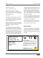
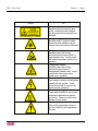
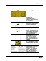
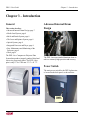
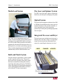
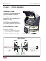
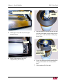
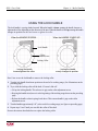
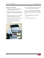
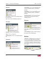
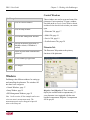
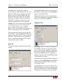
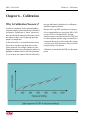
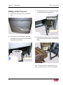
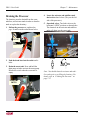
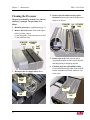
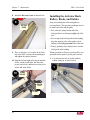
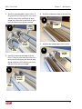
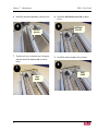
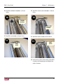
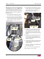
DPX 4 / Fredia
User Guide
AO302471
Revision 3
Preface
DPX 4 User Guide
Preface
Copyright
ECRM contact information
© Copyright 2009 ECRM Imaging Systems
All rights reserved.
ECRM Imaging Systems
554 Clark Road
Tewksbury, MA 01876
USA
Tel: +001 978-851-0207
Fax: +001 978-851-7016
DPX 4 / Fredia User Guide
December 2009
Web: www.ecrm.com
Doc. No. AG302471, Rev. 3
This manual and the software it describes are
provided under licence and may only be used or
copied in accordance with the terms of that
licence. The information in this manual is subject
to change without notice and should not be
construed as a commitment by ECRM Imaging
Systems. ECRM Imaging Systems assumes no
responsibility or liability for any errors or inaccuracies that appear in this manual.
All rights reserved. No part of this manual may be
reproduced or transmitted in any form, or by any
means, without the prior written permission of
ECRM Imaging Systems.
Windows is a registered trademark of Microsoft
Corporation.
All other brand or product names are trademarks
or registered trademarks of their respective
companies or organizations.
ii
DPX 4 User Guide
Table of Contents
Preface 2
Chapter 1 – Using this Guide
Navigating this guide in Acrobat Reader ..........................................................................................1
Bookmarks ...........................................................................................................................1
Using hot links .....................................................................................................................1
Warnings and notes .....................................................................................................................2
Warnings ..............................................................................................................................2
Notes ....................................................................................................................................2
Printing this guide .......................................................................................................................2
Chapter 2 – Safety
General ...............................................................................................................................................3
Laser ..................................................................................................................................................3
Regulatory Information .....................................................................................................................3
Electromagnetic Emissions .........................................................................................................3
Safety Labels .....................................................................................................................................4
Chapter 3 – Introduction
General ...............................................................................................................................................7
Advanced Internal Drum Design .......................................................................................................7
Power Switch .....................................................................................................................................7
Media Load System ...........................................................................................................................8
Knife and Punch System ....................................................................................................................8
The Laser and Spinner System ..........................................................................................................8
Optical System ...................................................................................................................................8
Integrated Processor and Dryer .........................................................................................................8
Easy Maintenance and Monitoring of the Processor .........................................................................9
Work ..................................................................................................................................................9
iii
DPX 4 User Guide
Chapter 4 – Media Handling
Media Load System .........................................................................................................................11
Inserting and Mounting Media .................................................................................................11
Removing the Media Roll ..................................................................................................11
Mounting a New Media Roll .............................................................................................14
Chapter 5 – Working with DotManager
General ............................................................................................................................................15
Menus ..............................................................................................................................................15
File menu ...........................................................................................................................16
View menu .........................................................................................................................16
Tools menu ........................................................................................................................16
Help menu ..........................................................................................................................16
Buttons .............................................................................................................................................16
Windows ..........................................................................................................................................17
Control Windows ......................................................................................................................17
Platesetter Tab ....................................................................................................................17
Media Tab ..........................................................................................................................19
Service Tab ........................................................................................................................19
EcoPreferences Tab ...........................................................................................................20
Setup Window ..........................................................................................................................21
Product License Keys ........................................................................................................22
RIP Management Windows ......................................................................................................22
Setup Tab ...........................................................................................................................23
License Tab ........................................................................................................................23
Spool Tab ...........................................................................................................................24
Imagesetter Tab ..................................................................................................................24
Chapter 6 – Calibration
Why Is Calibration Necessary? .......................................................................................................27
Chapter 7 – Maintenance
General ............................................................................................................................................29
Opening the Processor Drawer and the Side Panels ........................................................................29
Pulling out the Processor .................................................................................................................30
Draining the Processor ....................................................................................................................31
iv
DPX 4 User Guide
Cleaning the Processor ....................................................................................................................32
Filling the Processor Chemistry ......................................................................................................33
Installing the Stabilizer Rack Rollers and Bottom Guide ................................................................38
Installing the Activator Rack Rollers, Racks, and Guides ..............................................................40
Cleaning the Activator Supply Pipe ................................................................................................44
Replacing the Diffusion and Anti-backflow Sheets ........................................................................45
Replacing the Backup Roller ...........................................................................................................45
Replacing the In-line Activator Filter ..............................................................................................46
Replacing a Supply Pump ................................................................................................................46
Lubricating the Worm Gears ...........................................................................................................47
Chapter 8 – Technical Specifications
Chapter 9 – Troubleshooting
Troubleshooting Table .....................................................................................................................53
Display Messages ............................................................................................................................53
Display Messages ............................................................................................................................54
v
DPX 4 User Guide
vi
DPX 4 User Guide
Chapter 1 – Using this Guide
Chapter 1 – Using this Guide
This section includes the following topics:
Bookmarks
• Navigating this guide in Acrobat Reader, page 1.
You can use the Bookmarks window to quickly
navigate to a specific chapter or section of this
manual. If the bookmarks are not visible, click on
the Bookmarks tab (see below) to display them:
• Warnings and notes, page 2.
• Printing this guide, page 2.
Note The instructions in this section are for
Acrobat Reader v7.0.
Navigating this guide in
Acrobat Reader
If you are using Acrobat Reader to view this guide,
we recommend you use the following Acrobat
navigation buttons:
BOOKMARKS
TAB
Go to the first page of the guide
Go back one page
Go forward one page
Click on a link to move to the relevant chapter.
Click on a
link to view the sub-sections
within a chapter.
Go to the last page of the guide
Using hot links
Go back to previous view
Go forward to next view
You can use Acrobat Reader’s ‘hot links’ to move
quickly to the section you want (when you place
the mouse cursor over a hot link it turns into a hand
icon).
Fit whole page in window
There are three types of hot link:
Close bookmarks
• On the Contents page: click on the entry to take
you to the relevant section.
1
DPX 4 User Guide
Chapter 1 – Using this Guide
• Cross references: you will find these throughout
the manual, for example, refer to “Printing this
guide” on page 1.2 for instructions. Click on the
section reference to take you to the relevant
page.
• On the Index page: click on the index entry to
take you to the relevant page.
Printing this guide
To print this guide:
1. In Acrobat Reader select Print… from the
File menu. A dialog similar to the one shown
below appears:
Warnings and notes
Warnings
The warnings in this manual are intended to
protect you from injury and/or to protect the DPX
4 engine and your plates from damage. Read all
warnings carefully and follow any instructions
they include.
Warnings appear in bold print, like this:
WARNING: When working with the DPX 4
system you must protect yourself from injury
and protect the DPX 4 engine from damage.
Notes
The notes in this manual give additional information on using the DPX 4 system.
Notes appear in italics, like this:
Note The instructions in this manual are for the
DPX 4 system.
2
2. Select the required printer from the Name
pull-down menu.
3. Click on the Properties button and select the
Portrait orientation on the Layout tab.
4. Click on OK to return to the Print dialog.
5. Set the other options, such as the page range,
then click on OK to print this guide (or the
specified pages).
DPX 4 User Guide
Chapter 2 – Safety
Chapter 2 – Safety
General
Laser
Although every precaution has been made to
produce a safe product, we strongly recommend
you comply with the following.
This system is classified as a Class one (I) laser
product that contains a Class 3B (IIIb) laser
system. This classification means that the operator
is exposed to no hazardous laser light during
operation and maintenance. The laser itself,
however, is a Class 3B (IIIb) laser device, and it
emits visible laser light which is considered
hazardous by FDA published limits.
• The equipment must be properly grounded when
connected to electrical outlets.
• Turn off power:
• before connecting or disconnecting cables,
and
• before carrying out maintenance or
adjustment operations.
• Do not remove covers or shielding.
• Do not install/use the equipment close to inflammable gases and vapors.
• Do not make any unauthorized modifications of
the equipment.
• Wear protective gloves when handling chemistry
and avoid spilling the fluids.
• Always check that the actual media width in
Media Management corresponds to the actual
media being used.
• The spinner in the platesetter cannot be started in
an ambient temperature of less than 15 degrees
Celsius.
• The equipment must be protected by a circuit
breaker appropriately rated for the machine.
When the panels are removed, an interlock system
automatically switches off the laser and optics unit
to insure against the risk of radiation.
IMPORTANT WARNING:Modifications to
the machine or performance of procedures
other than those specified in this guide may
result in hazardous laser light exposure.
Regulatory Information
Electromagnetic Emissions
DOC- Canada
The Canadian Department of Communications
requires compliance with the Radio Interference
Regulations, ICES -003.
This digital apparatus does not exceed the Class A
limits for radio noise emissions from digital
apparatus set out in the Radio Interference Regulations of the Canadian Department of Communications.
3
DPX 4 User Guide
Chapter 2 – Safety
EMC Directive - Europe
Complies with EN 55011: 1998
This is a Class A product. In a domestic
environment this product may cause radio interference in which case the user may be required to
take adequate measures.
FCC - USA
The standards for electromagnetic emissions are
Part 15, Subpart J of the FCC rules. The system
was tested to Class A limits. The following statements are required by the FCC:
Changes or modifications to this unit not expressly
approved by the party responsible for compliance
could void your authority to operate the
equipment.
This equipment has been tested and found to
comply with the limits for a Class A digital device,
pursuant to Part 15 of the FCC Rules. These limits
are designed to provide reasonable protection
against harmful interference when the equipment
is operated in a commercial environment. This
equipment generates, uses, and can radiate radio
ECRM Incorporated
554 Clark Road
Tewksbury, MA, USA
MODEL NUMBER:
SERIAL NUMBER:
MANUFACTURED:
RATING:
frequency energy and, if not installed and used in
accordance with the instruction guide, may cause
harmful interference to radio communications.
Operation of this equipment in a residential area is
likely to cause harmful interference in which case
the user will be required to correct the interference
at his or her own expense.
Compliance with applicable regulations depends
on the use of shielded cables, which the user may
be responsible for procuring.Identification and
Certification Label (ratings plate)
The identification and certification label shown
below is attached to the cover of the platesetter
unit, near the power entry receptacle.
Safety Labels
A variety of safety labels are located throughout
the DPX 4 to alert users and service personnel to
potentially hazardous areas of the machine. The
safety labels are shown and explained on the next
two pages.
N13777
CLASS 1 LASER PRODUCT
This product conforms to all applicable provisions of Federal
Regulations 21 CFR Chapter 1, Subchapter J, Section 1040.10.
This device complies with Part 15 of the FCC Rules. Operation is
subject to the following two conditions: (1) this device may not
cause harmful interference, and (2) this device must accept any
interference received including interference that may cause
undesired operation.
This Class A digital apparatus complies with Canadian ICES-003
ATTENTION: Refer to the user guide
for safe operation of this product
4
DPX 4 User Guide
Chapter 2 – Safety
Symbol
Use
Laser Hazard, interlocked:
Identifies interlocks used for laser
safety. Hazardous laser radiation
may be present when interlocks are
defeated.
Laser Hazard, general:
Identifies areas of machine where
hazardous laser radiation may be
present when interlocks are defeated.
Pinch/shear hazard:
Identifies areas with moving
mechanical parts where a pinch or
shear hazard exists. Avoid contact
with these areas when machine is in
operation.
Entanglement hazard:
Identifies areas with moving
mechanical parts where an
entanglement hazard exists. Avoid
contact with these areas when
machine is in operation.
Electrical Hazard:
High voltage is present behind panels
marked with this symbol. These
panels should only be removed by
trained service personnel.
Hot surface warning:
Panels marked with this symbol and
components behind these panels
may be hot. Observe caution when
working in these areas.
Attention symbol:
Refer to the appropriate section of
the User Guide for safe operation in
this area.
5
DPX 4 User Guide
Chapter 2 – Safety
Symbol
Use
Processor chemistry warning.
Fuse identification:
Fuses must be replaced by
components with identical voltage
and current ratings.
Momentary switch:
Used to identify switches that are
activated only when pressed.
Protective earth:
Identifies the point where
protective earth is attached to the
machine chassis. Protective earth
should only be disconnected by
trained service personnel.
Chassis ground:
Identifies attachment points for
chassis ground for electrical
safety. These attachments must
be maintained for safe operation of
the product.
Rotational hazard:
Wait 20 seconds before access to
any area marked with this symbol.
Certification label:
Identifies machine model number,
serial number and date of
manufacture. Also identifies the
operating voltage, frequency,
current, user replaceable fuse (if
equipped) and certifications.
6
DPX 4 User Guide
Chapter 3 – Introduction
Chapter 3 – Introduction
General
This section describes:
Advanced Internal Drum
Design
• Advanced Internal Drum Design, page 7
• Media Load System, page 8
• Knife and Punch System, page 8
• The Laser and Spinner System, page 8
• Optical System, page 8
• Integrated Processor and Dryer, page 8
• Easy Maintenance and Monitoring of the
Processor, page 9
• Work, page 9
The DPX 4 is a Computer-to-Polyester Plate
System that produces imaged, punched, dried and
cut-to-size press-ready plates. The DPX 4 foot
print is only 1370 x 1060 mm / 53.9" x 41.73".
The DPX 4 uses an extruded aluminum drum to
achieve extremely high precision and accuracy.
Power Switch
The main power switch for the DPX 4 platesetter
is located on the back panel, as shown below.
POWER
SWITCH
7
DPX 4 User Guide
Chapter 3 – Introduction
Media Load System
The Laser and Spinner System
The DPX 4 uses fiber optic cables to transmit the
dot directly into the optics and high-speed spinner.
Optical System
The optical system supports resolutions from 1000
to 3000 dpi in steps that insure the correct spot size
and laser intensity for the selected resolution, as
well as automatic focus which ensures the
optimized spot on the plate producing high quality
four color print.
Integrated Processor and Dryer
DPX 4 has a twin-compartment media load
system. An auto-centering system ensures precise
centering of new media on the shaft every time a
new roll is loaded. During operation, the media is
automatically advanced onto the drum where it is
held in place by a vacuum system during exposure
The two media compartments permit the DPX 4 to
simultaneously hold two different media sizes.
The built-in processor includes an activator unit, a
stabilizer unit, and a dryer. There is a temperature
control for the activator tank. Both tanks have
sensors for controlling the chemistry level and
DRYER
STABILIZER
ACTIVATOR
Knife and Punch System
The plate material is punched by a built-in punch
system, exposed, and cut to size. This gives a
precise and even registration from plate to plate
and ensures minimum mounting time and easy
registering of the plate on the press. The DPX 4
comes with a Bacher 425 mm punch as standard. It
can be field upgraded with a Bacher 220 mm as
well as Komori 550 mm custom punch.
Note: Covers, racks and guides have been
removed to show interior parts.
8
DPX 4 User Guide
active replenishment to ensure the correct level of
new chemistry in the tanks and to achieve precise
activation of the polyester plate.
Chapter 3 – Introduction
integrated operation with the ECRM WorkMates
work program. The interface between the DPX 4
and the RIP PC operates via a USB-2.0 port.
A 30-liter waste container collects excess
chemistry and alerts the user when full. A drain
pump provides for emptying the waste container
without draining the chemistry.
Easy Maintenance and
Monitoring of the Processor
The processor is mounted on wheels. A guide
allows it to be rolled out easily for maintenance or
chemistry replenishment.
The DotManager program controls and monitors
the processor and displays real-time processor
status information on the PC monitor.
Work
The DPX 4 is controlled by a Win2000 or WinXPbased RIP platform. The DotManager program
controls the media and the processor and
9
Chapter 3 – Introduction
10
DPX 4 User Guide
DPX 4 User Guide
Chapter 4 – Media Handling
Chapter 4 – Media Handling
Media Load System
The DPX 4 has a twin-compartment media load
system that accommodates two plate sizes.
Each compartment includes an auto-centering
media spindle (see below). Its mechanism ensures
precise centering of the media on the shaft every
time a new roll is loaded.
TOP COVER
During operation the media is automatically
advanced, positioned in the drum, and held in
place by a unique vacuum system during exposure.
Inserting and Mounting Media
UPPER COMPARTMENT
(STANDARD)
Removing the Media Roll
1. Make sure the media is unloaded (Unload
button on DotManager's Control Windows).
LOWER COMPARTMENT
(OPTIONAL)
2. Lift up the top cover (see figure at right).
Twin-compartment
MEDIA SPINDLE
LOCK
END CAP
MEDIA
END CAP
Centerline
LOCK
HANDLE
FIXED
FLANGE A
TOOTHED
WHEEL
FIXED
FLANGE B
11
DPX 4 User Guide
Chapter 4 – Media Handling
UPPER AND LOWER LIGHT COVERS
3. Lift the upper or (in this case) lower light
protection cover.
LOCK HANDLE
IN HOME
POSITION
5. Place the media roll vertically on the floor and
move the lock handle from the home position
shown above to the end of the working range
shown below.
WORKING RANGE
END CAP
LOCKING
COLLAR
LOCK HANDLE
AT FAR END OF
WORKING RANGE
4. Gently lift the media roll out of its
compartment by the end caps.
6. Set one foot on the media end cap and pull the
locking collar and the lock end cap off the
shaft.
7. Lift the media roll off the shaft.
12
LOCK
END CAP
DPX 4 User Guide
Chapter 4 – Media Handling
USING THE LOCK HANDLE
The lock handle is a spring-loaded wrench. When the handle is down, turning the handle loosens or
tightens the collar, depending on the direction of the turn. When the handle is held up, turning the handle
changes its position but does not loosen or tighten the collar.
When the HANDLE IS HELD UP...
When the HANDLE IS DOWN...
Lock Handle
Collar
Adjustment Screw
Locking Collar
...turning the handle
loosens/tightens the collar.
...turning the handle
merely changes its position.
Here’s how to use the lock handle to remove the locking collar.
1. Turn the lock handle from home position to the end of its working range. (See illustrations on the
preceding page.)
2. Try to slide the locking collar off the shaft. If it won’t slide off:
• Lift up the locking handle. This releases its grip on the collar adjustment screw.
• Keeping the handle raised, move it to the beginning of the working range shown on the preceding
page.
• Release the handle so that it springs back down. This restores handle’s grip on the collar
adjustment screw.
3. Turn the handle approximately 180°, to the end of its working range (see figure on preceding page).
4. Repeat steps 2 and 3 until you can slide the collar off the shaft.
Reverse the actions described above to replace the locking collar.
13
DPX 4 User Guide
Chapter 4 – Media Handling
Mounting a New Media Roll
1. Slide the media onto the shaft and make sure it
fits tightly against the media end cap.
6. Carefully remove the tape from the media and
advance the roll towards the input edge.
2. Push the lock end cap onto the shaft. Note that
the media roll is automatically centered on the
shaft.
Note Be sure to completely remove all the tape
from the new media roll. Tape or tape remnants left
on the media could damage the inside of the drum
in time.
3. Slide the locking collar onto the media shaft
and then up against the lock end cap.
7. Press the Preload button to advance the
media.
4. Lock the collar in place. Refer to the Using the
Lock Handle on the preceding page.
8. Close the light protection cover.
5. Place the shaft with the media roll in the
compartment.
INPUT
EDGE
TAPE
14
DPX 4 User Guide
Chapter 5 – Working with DotManager
Chapter 5 – Working with DotManager
General
DotManager is the user interface for the DPX 4. It
runs as a separate application on the RIP PC and
communicates with the platesetter through a USB
interface.
Note The DPX 4 does not have a control panel.
The user communicates with the machine through
the DotManager program. DotManager is
installed with the RIP, from the CD.
The DotManager interacts with the RIPMate RIP
by providing license management for the ECRM
specific options, starting/stopping the RIP, and
providing device services.
DotManager opens with the splash screen below.
In this section:
• Menus, page 15
• Buttons, page 16
• Windows, page 17
Menus
DotManager has four pull-down menus:
• File menu
• View menu
The splash screen remains for a few seconds, then
switches to the main screen shown in the next
figure.
• Tools menu
• Help menu
PULL-DOWN
MENUS
15
DPX 4 User Guide
Chapter 5 – Working with DotManager
File menu
Start RIPMate: Click to start the RIPMate application (or WorkMates Admin, if PrintMate is
installed).
Stop RIPMate: Click to stop the RIPMate appli-
cation (or WorkMates Admin, if PrintMate is
installed).
Start Hyperterminal: Click to start the hyperterSave Changes: Click to save any changes made to
the current setup.
minal communication application used for
debugging purposes.
Exit: Click to exit the DotManager application.
Help menu
View menu
Online Help: Click to view the Online Help on-
screen.
Platesetter: Click to view Platesetter tab
About DotManager: Opens a window displaying
the current version of DotManager.
Setup: Click to view Setup tab
Rip Management: Click to view Rip Management
tab.
Tools menu
Buttons
Additionally, DotManager has seven buttons for
accessing various control and set-up windows,
starting/stopping RIPMate (or WorkMates Admin,
if WorkMates is installed), starting the Hyperterminal, quitting DotManager, and saving changes
(left to right):
BUTTONS
16
DPX 4 User Guide
Chapter 5 – Working with DotManager
Control Windows
DotManager buttons
access the Control Windows
access the Setup Window
These windows are used to set up and control the
platesetter’s basic operation. To open a window,
first click on the access the Control Windows button,
and then click on the tab for the window you want to
open.
• Platesetter Tab, page 17
access the RIP Management Windows
• Media Tab, page 19
• Service Tab, page 19
• EcoPreferences Tab, page 20
start/stop the RIPMate application (or
WorkMates Admin, if PrintMate is
installed)
Platesetter Tab
start the Hyperterminal communication
application
The Platesetter Tab pertains to the primary
functions of the platesetter.
exit the DotManager application
save changes
Windows
DotManager has different windows for setting up
and controlling the platesetter. The windows fall
into three basic categories:
• Control Windows, page 17
• Setup Window, page 21
• RIP Management Windows, page 22
Note In this section, all the examples and screen
views use metric measurement units. The
measurement unit can be changed to imperial
units on the Setup tab.
Magazine 1 and Magazine 2: These sections
display the available media compartment(s). If
your platesetter is not equipped with the extra
optional compartment, Magazine 2 compartment
will be greyed.
17
DPX 4 User Guide
Chapter 5 – Working with DotManager
Preload/Unload: When a media roll has been
inserted in the media compartment, click the
Preload button to advance the media into the feed
system. When the media is loaded, the button text
changes to Unload, and the button is then used for
pulling the media out of the feed system, e.g. in
case of replacement.
Form Feed: Click the Form Feed button to
advance the media 68 cm (maximum exposable
film length).
Start/Stop Sweep Mode: Click this toggle button to
activate or deactivate the Exposure Sweep mode.
The Exposure Sweep Mode provides for multiple
RIP jobs to be exposed on one plate. The platesetter automatically feeds the plate out, when it is
full, or when the RIP does not supply new jobs
within 15 seconds from the last completed job. See
also Calibration in the RIPMate User Manual.
Activate/Standby: Toggles the system’s operating
mode.
Click Standby to switch the platesetter to an
energy-saving “shut down” mode that turns off
motors, pumps and other electrical devices.
3. If the Auxiliary Thermal Control hardware is
installed, the processor turns on the drum
heater if the internal temperature is less than
18° C.
Click Activate to switch the platesetter back to a
normal operating mode.
Status: The Status section includes a number of
status lamps for Load, Unload, Prepare Media,
Punch, Expose, Feed, Cut, Feed to Processor,
Processor, and Conveyor activities in the
processor. Some signals from the lamps are
accompanied by an additional message in the
activity window below the lamps.
Temperatures: Displays the current temperature of
the Activator and the Dryer. Also, displays the
stabilizer temperature if the Auxiliary Thermal
Control hardware is installed.
Platesetter Status: The traffic light indicates the
current state of the platesetter at all times and
responds to the color indicators in the Status
section.
• Red: Error
Notes
• Orange: Warning
1. The processor automatically flushes the
activator coater and cleans the activator
remover mechanism before shutting down. If
the Auxiliary Thermal Control hardware is
installed, the processor turns on the drum
heater and stabilizer heater as necessary to
bring the internal temperature up to 18° C.
• Green: OK
2. The processor automatically flushes the
activator coater at time 0:00 (i.e., when the
processor’s clock turns over to start a new 24hour cycle).
18
Message Log: The Message Log window next to
the traffic light displays general messages relating
to the data connection between the DotManager
and the platesetter.
DPX 4 User Guide
Chapter 5 – Working with DotManager
Media Tab
2. Change the appropriate settings.
The Media window displays a list of cassettes with
information about what media type is loaded in the
cassette, length of remaining media, and media
thickness.
3. Click the Save button.
Service Tab
The Service window displays some general info
about the platesetter usage, tools to manage the
activator and stabilizer pumps.
It is possible to create new cassettes and edit
existing cassettes.
Media Drop Down list: Displays the list of media
configured for the platesetter. Maximum 16
different media can be configured.
Name: Enter a name for the new media as you
want it to appear in the drop down list.
Width: Enter the width (mm) of the new media.
Thickness: Enter the thickness (mm) of the new
media.
Expose Punch Zone: Click the check box to choose
to use the punch zone for exposure. (The quality of
exposure in this area cannot be guaranteed.)
The I/O test window is started from the Service
window.
General
The General section displays some common
statistics about the platesetter utilization. All these
parameters are lifetime information of the platesetter.
Total Operating Time: Displays the total number of
hours with power on.
Total Area processed: Displays the total number of
hours activated (not counting standby time).
To change a media setup:
1. Select the correct media in the drop down list.
Total Black Area Processed: Displays the total
number of square meters processed.
19
DPX 4 User Guide
Chapter 5 – Working with DotManager
Total Plates: Displays the total number of plates
processed.
Pump replacement instructions are presented in
“Replacing the In-line Activator Filter” on
page 46
Refill
Activator: Refill the activator rack until it is
EcoPreferences Tab
completely full.
The EcoPreferences window displays values that
are derived directly from the platesetter processor.
Stabilizer: Refill the stabilizer rack until it is
completely full.
Note These functions are performed automatically when the tank level is low.
Add Volume
Activator: Add the indicated volume to the
activator rack.
Stabilizer: Add the indicated volume to the stabi-
lizer rack.
I/O Test button
Opens the - service-password protected - I/O Test
window.
This I/O Test window communicates with the
relevant subsystems in the platesetter or processor
and is meant for service personnel only.
Supply Pump Service
This section includes two indicators that turn red
when it is time to replace the activator pump
and/or the cleaning pump. (Every 25,000 plates for
the activator pump; every 50,000 plates for the
cleaning pump.) After you change either pump,
press the “Done” button to reset the pump’s plate
counter to zero. (0).
Note When pump service is required, you will be
notified when you start of Dot Manager.
20
Processing
Activator Time: Specifies the time (in seconds) the
activator is applied to the media.
Activator Replenishment Rate: Specifies the
volume of activator fluid that has to be replenished
in milliliter per square meter of developed plate.
Stabilizer Replenishment Rate: Specifies the
volume of stabilizer fluid that has to be replenished in milliliter per square meter of developed
plate.
Dryer Temperature: Specifies the temperature of
the dryer air in centigrade (°C).
DPX 4 User Guide
Activator Temperature: Specifies the temperature
of the activator fluid in centigrade (°C).
Flow Rate Index: Sets the activator flow rate. The
default setting is 7. The higher the setting number,
the higher the flow rate.
Anti Oxidant
Chapter 5 – Working with DotManager
Coater (Activator Coater)
The processor employs a mechanism for coating
activator on the plates. Activator residue that
builds up on this mechanism hardens if it stays on
the mechanism too long. To prevent this from
happening, you can configure the processor to
automatically flush the mechanism clean at regular
intervals.
Activator Replacement: Specifies the volume of
activator fluid that has to be replenished in milliliter per hour beginning after the idle period.
Flush Idle: Sets the length of time between
Stabilizer Replacement: Specifies the volume of
Flush Cycle: Sets the duration of the flushing
stabilizer fluid that has to be replenished in milliliter per hour beginning after the idle period.
operation. The default setting is 30 seconds.
flushes. The default setting in 10 minutes.
Flush Flow: Sets the activator flow rate for the
flushing operation. The default setting is 200ml/m.
Cleaning Cycle (for the Activator Remover)
Power On Volume
The processor has a mechanism for removing
excess activator from the plates. Activator residue
that builds up on this mechanism hardens if it stays
on the mechanism too long. To prevent this from
happening, you can configure the processor to
automatically clean the mechanism after
remaining idle for a period of time.
Activator Replenish: Defines the volume of the
Clean Idle Period: Sets the length of time the
activator replenishment. The default setting is 100
ml.
processor can remain idle before the cleaning is
performed. The default setting in 60 minutes.
Note This cleaning is a one-time event. Once the
mechanism is cleaned, the system will not perform
a subsequent cleaning regardless of how long the
processor remains idle.
Idle Cleaning Time: Sets the duration of the
cleaning. The default setting is 30 seconds.
Power Down Cleaning Enable: Enables/disables
cleaning of the activator remover mechanism on
power-down.
At initial power up, the processor automatically
replenishes the activator and stabilizer supplies.
The following parameters provide for defining
replenishment volumes
Stabilizer Replenish: Defines the volume of the
stabilizer replenishment. The default setting is 100
ml.
Note Replenishment may or may not occur
depending on whether the “Reduced Power-on
cycle delay” period has elapsed.
Setup Window
The Setup window displays a series of platesetter
related settings.
21
DPX 4 User Guide
Chapter 5 – Working with DotManager
To open the window, first click on the access the
Setup Window button.
Product License Keys
Attached Dongle: Serial number of the USB
dongle plugged in the RIP PC.
Configured Dongle: Serial number of the USB
dongle which is configured in the platesetter
firmware.
License Keys input fields: Enter the appropriate
license key to activate certain extra (license
protected) platesetter functions.
Update Dongle Configuration: After entering the
license key(s) click the Update Dongle Configuration button to save the new license(s) in the
platesetter firmware.
RIP Management Windows
The displays and dialogs are as follows.
Current Firmware version: Displays the current
firmware version in the platesetter.
Download Firmware: Use this button to download
or update the platesetter firmware to your platesetter. The program will guide you through the
download process. (To update your platesetter
firmware, first shut down RIPMate.)
The RIP Management windows are used to set up
and control the platesetter’s basic operation. To
open a window, first click on the access the RIP
Management Windows button, and then click on the
tab for the control window you want to open.
• Setup Tab, page 23
• License Tab, page 23
• Spool Tab, page 24
Measurement Units: Click to open and choose
between Metric and Imperial units.
Clear log: Click the button to delete the
dotmanager.log-file.
Debug Log: Enable/disable a debug log: When
debugging is enabled, DotManager will record all
information about the communication with the
platesetter and processor into a plain text file. This
file can be consulted at \Ripxxx\DotManager.log.
22
• Imagesetter Tab, page 24
DPX 4 User Guide
Chapter 5 – Working with DotManager
prevent RIPMate from generating an error
message when it does not find an platesetter
attached to your computer.
License Tab
Setup Tab
Rip Folder: DotManager needs to be able to find
RIPMate on your hard disk, so that it can send
instructions and launch RIPMate when it needs to.
If you move RIPMate to a new folder, you must
enter the new path in the Rip Folder directory field
by either typing it directly or using the Browse
button to find it.
Automatic startup of RIP: DotManager must run
The License tab enables the ECRM specific
WorkMates options by entering the appropriate
password.
Note This tab is not available if WorkMates
Administrator is installed.)
before RIPMate. This enables DotManager to
establish communication with RIPMate and to
control the media management features.
Therefore, when you want to start running
RIPMate, you must begin by running
DotManager. For convenience, DotManager can
start RIPMate automatically thereafter. To activate
this feature, mark the Automatic Startup of RIP
check box.
Extended Workflow: The Extended Workflow
option provides extra support for larger, multi-user
installations. It adds RipSpool, a dedicated input
plug-in.
Proofer only (disable platesetter functionality):
ProofMate: The ProofMate proofing option lets
Disables the platesetter-only features of RIPMate
so that you can use it simply to drive a proof
printer. If you are using RIPMate only to drive a
proof printer (possibly using the ProofMate
option), then you should mark this check box to
you use any low- or high-end printer or plotter as
a proofing device. The only thing you need is a
standard Windows printer driver. With ProofMate,
any of thousands of printers can be used for
proofing at the cost of just one printer driver.
These options are:
Note For RIPMate 7.1and higher this option is
no longer license-protected.
23
DPX 4 User Guide
Chapter 5 – Working with DotManager
ProofMate allows simultaneous output to a
proofer and to any other output device, such as an
platesetter. While you are sending one job to the
proofer, you can be sending another job to the
platesetter, thus greatly improving your output
productivity. ProofMate makes use of industrystandard ICC profiles to provide precise color
reproduction and final press color emulation.
CIPMate: CIP3 files are used to link printing and
Network Spool Folder: Enter the complete path for
the folder to use for spooling, or use the Browsebutton for locating the folder.
Windows Printer Driver: Click to open the drop-
down list box and select the appropriate Windows
printer driver installed on the RIP PC.
Imagesetter Tab
post-printing processes closer to the prepress
phase. With the CIPMate option, RIPMate
generates CIP3 files on the fly as the platesetter is
driven, using exactly the same screened data.
This means that the PostScript job only has to be
processed once, compared with systems that use a
separate output driver for CIP3. Thus, only half as
much time is required, and the cost and inconvenience of maintaining a duplicate CIP3 setup for
each platesetter setup is avoided.
Spool Tab
The Spool tab displays information about spooler
settings.
Stop on page errors: This check box determines
how RIPMate will react to a page that contains
errors, such as incorrect margins or corruption. If
this check box is marked, all further output will be
disabled from RIPMate until it is explicitly reenabled via the check box in the RIPMate Output
Controller/Monitor window.
If this check box is unmarked, all pages with errors
will be moved to the Held Queue in the RIPMate
Output Controller/Monitor window. Other jobs
will continue to print.
Stop on media out: This check box applies only to
platesetters that have more than one input cassette
(like the DotMate 5000). It controls what RIPMate
will do if one of the cassettes runs out of media.
24
DPX 4 User Guide
If this check box is marked, all further output will
be disabled from RIPMate until the cassette is
refilled and output it is explicitly reenabled via the
check box in the RIPMate Output
Controller/Monitor window.
If this check box is unmarked, RIPMate will move
all jobs requesting out-put to the empty cassette
into the Held Queue. However, if the Smart
Cassette check box is marked, RIPMate will
output to the other cassette, provided it contains
the correct media. Jobs requesting the other
cassette will be processed as usual.
Maximum Data Rate: The first time you run
RIPMate, this field will be set to zero. RIPMate
will then test your system to find out how fast data
can be sent to the platesetter. If you are having
frequent problems with pages caught ups, you may
need to set this field back to zero so that RIPMate
can recalculate a reasonable rate. Otherwise, you
should never change the value of this field.
Safety Factor: The safety factor forces RIPMate to
assume communication will be slightly slower
than the value found for Maximum Data Rate. A
safety factor of 5% should be sufficient, but if
recalculating the Maximum Data Rate, as
suggested above, does not help reduce page caught
ups, try to raise this value slightly.
Chapter 5 – Working with DotManager
If this check box is marked, and the Retry on
printer caught ups check box is unmarked,
RIPMate will disable all further output each time a
caught up occurs. Output will remain disabled,
until it is re-enabled in RIPMate's Output
Controller/Monitor window.
If this check box is marked, and the Retry on
printer caught ups check box is also marked,
RIPMate will try to resend the page at half speed.
If it catches up again, RIPMate will try at one
quarter speed. If it catches yet again, RIPMate
disables all further output.
If this check box is unmarked, and the Retry on
printer caught ups check box is unmarked,
RIPMate will move the job into the Held Queue.
Other jobs will print as usual.
If this check box is unmarked, and the Retry on
printer caught ups check box is marked,
RIPMate will retry at the two slower speeds, but it
output is still not possible, the job will be moved
into the Held Queue. Other jobs will print as
usual.
Retry on printer caught ups: This check box
controls weather or not RIPMate will try to output
at a slower speed, if a caught up occurs at the usual
speed. See the description for Stop on printer
caught ups above for more information.
Stop on printer caught ups: When the RIP is unable
to provide the platesetter with data at the correct
speed (due, for example, to excessive loads on the
processor or network), the output will be interrupted. In this case, the platesetter must stop
output.
This check box determines what RIPMate will do
in the event of a caught up.
25
Chapter 5 – Working with DotManager
26
DPX 4 User Guide
DPX 4 User Guide
Chapter 6 – Calibration
Chapter 6 – Calibration
Why Is Calibration Necessary?
In order to compensate for dot gain and produce
consistent output, a platesetter must be calibrated
for linearity. A platesetter is “linear” when every
tone specified in the input gives that same tone in
the output, so that a curve comparing input and
output is a straight line.
In four-color work, even small deviations from a
linear curve can cause significant errors in the
colors produced - for example, changes in color
balance and contrast, loss of brightness, and loss of
highlight or shadow detail. Even if the platesetter
is very accurate, the output will still be affected by
the type and brand of media used, so calibration
should be regularly checked.
Because of the way DPX 4 moderates its exposures,
it is recommended that you sweep from 200 to 1200
at steps of 200. As illustrated below, the light
intensity response is notched at intervals of 200, and
to achieve optimum dynamic range you should use a
setting near the top of one of the notches. By creating
a sweep in steps of 200 that starts at 200, you will be
testing at the top of each notch.
Calibration is described in the RIP user documentation.
.
27
Chapter 6 – Calibration
28
DPX 4 User Guide
DPX 4 User Guide
Chapter 7 – Maintenance
Chapter 7 – Maintenance
General
You must keep the processor clean to obtain highquality output.
As the media passes through chemistry, it inevitably leaves residue on the rollers in the processor
racks. For that reason,
• any part of the processor unit which is passed by
the media should be cleaned at least once a week,
or at regular intervals,
• the processor should be cleaned at each change
of chemistry,
Opening the Processor Drawer
and the Side Panels
Whenever the processor is drawer pulled out or a
side panel is opened, the interlock system halts
operations and switches off the laser and optics
unit. When the drawer or side panel is closed, the
laser and optics unit are turned back on, but the
operations that were halted may or may not
resume, depending on their state when they were
halted.
open cover
• any chemical residue on the drain hose and hose
coupling should be removed.
SIDE PANEL
INTERLOCK
SWITCH
The punch waste container located behind the lefthand side door (see below) should be emptied at
regular intervals. The transparent part of the
container can be unscrewed by turning it counterclockwise.
open cover
PUNCH WASTE
CONTAINER
PROCESSOR
INTERLOCK
SWITCH
To ensure operations close and open in a orderly
manner, we recommend you power down the
DPX 4 before pulling out the processor drawer
or opening either side panel.
29
DPX 4 User Guide
Chapter 7 – Maintenance
Pulling out the Processor
3. To unlock the processor, turn the lock handle
to vertical position as shown below.
1. Press on the area shown below to open the
cover.
UNLOCKED
PRESS HERE
TO OPEN COVER
2. Pull out the cover and locate the processor
lock handle, which is positioned horizontally
when locked (see below).
LOCK HANDLE
4. Pull out the processor unit as far as permitted
by the cable chain. Be careful to avoid spilling
fluids.
CABLE
CHAIN
LOCKED
LOCK HANDLE
Note: The processor unit is supported by rails
while in position and by wheels when pulled out.
30
DPX 4 User Guide
Chapter 7 – Maintenance
Draining the Processor
The chemistry must be drained from the waste,
stabilizer, and activator tanks in order to clean the
tanks or replace the chemistry.
1. Pull out the processor as explained on
page 30 and locate the outlet shown below.
4. Locate the activator and stabilizer tank
drain valves show below. (They are the left
side of the processor.)
5. Open both valves. Turn both valves to the
horizontal “OPEN” position, as shown below.
The chemicals in the activator and stabilizer
tanks will drain into the waste tank.
OUTLET
OUTLET
DRAIN HOSE
DRAIN HOSE
CLOSED
2. Push the drain hose into the outlet until it
locks.
3. Drain the waste tank. Press and hold the
drain pump switch to activate the waste pump.
Release the switch when the waste tank is
empty.
DRAIN PUMP
SWITCH
OPEN
Note: You should clean the activator and stabilizer tanks prior to re-filling the chemistry. For
details, refer to “Cleaning the Processor” on
page 7.32
WASTE TANK
31
DPX 4 User Guide
Chapter 7 – Maintenance
Cleaning the Processor
The processor should be cleaned every time the
chemistry is changed. The procedure is as
follows.
4. Remove the nuts and loosen the captive
fasteners that secure the racks to the processor
chassis (see below).
STABILIZER
RACK
1. Drain the processor as explained on page 31
NUT
ACTIVATOR
RACK
2. Remove the rack covers. Refer to the figure
below. In order, remove:
(1) the inlet guide, (2) the activator cover, and
(3) the stabilizer cover.
STABILIZER ACTIVATOR
COVER
COVER
INLET
GUIDE
CAPTIVE
FASTENER
5. Remove the racks. Pull each one out by
grasping the handles at either end of the rack
and then pulling it straight up and out.
3. Disconnect the two supply tubes shown
below from the tee fittings.
6. Clean the activator and stabilizer tanks.
Pour clean water into the tanks, clean with Phneutral soap and a soft brush, and rinse with
clean water.
WATER
SUPPLY
TUBE
ACTIVATOR
TANK
ACTIVATOR
SUPPLY
TUBE
32
STABILIZER
TANK
DPX 4 User Guide
7. Let the water run off the rack before putting
it back in position.
8. Finish by draining the cleaning water from
the waste tank.
9. Remove any chemical residue on the drain
hose and hose coupling.
10. Clean the rollers, racks and guides in the
activator and stabilizer racks. Clean with a
soft brush and lukewarm water. Finish by
rinsing the parts with clean water.
If you have a large wash sink at your disposal,
you can just set the racks down in the sink and
clean with the rollers, guides, and racks still in
place in the rack.
However, to achieve optimal results, we
recommend cleaning the activator and
stabilizer racks as follows:
• Remove all the rollers racks, and guides
from the racks.
• Thoroughly clean and rinse the gear
trains inside the racks.
• Thoroughly clean and rinse the
individual rollers racks and guides
outside the rack.
• Clean the activator supply pipe as
explained in “The procedure for cleaning
the activator supply pipe is as follows.” on
page 7.43
• Place the cleaned parts back into place in
the rack.
The next four pages show the removable parts and
how they are arranged in the activator and stabilizer racks. Instructions for replacing the
removable parts follow the illustrations.
Chapter 7 – Maintenance
Filling the Processor Chemistry
1. Clean the processor as explained in the
preceding section.
2. Turn the drain valves to the vertical
“CLOSED” position, as shown below.
DRAIN HOSE
3. Add new chemicals - 1.3 liters of Activator,
and 5.8 liters of Stabilizer.
IMPORTANT: Avoid splashing stabilizer into
the activator tank. Even a small amount of
stabilizer may damage the activator.
Note: To minimize chemistry waste, do not
attempt to fill tanks to capacity. The processor will
automatically refill the remaining required
quantity upon power up.
4. Replace the activator and stabilizer racks.
5. Replace rack covers and inlet guide.
6. Gently push the processor unit back into
position.
7. Turn the processor lock handle to
horizontal position to lock the processor.
The activator temperature is regulated by means of
a computer-controlled heating element and must
be between 20° C (68°F) and 33°C (91°F).
WARNING: Never turn on the power unless the
processor unit is filled or the power plug for the
heating element is removed, as this may cause
overheating and damage to the processor unit.
33
Chapter 7 – Maintenance
Removable Parts, Activator Rack
1
2
3
4
5
6
7
8
9
10
11
12
13
34
DPX 4 User Guide
DPX 4 User Guide
Chapter 7 – Maintenance
ACTIVATOR RACK
2
3
4
1
12
25MM
WITH GEAR
13
FRONT
11
30MM TAPERED
25MM
WITHOUT GEAR
(Inside wall, left/gear-train side of rack)
WITHOUT GEAR
10
8
5
30MM
WITH GEAR
9
BACKUP
6
7
GEAR AT BOTH ENDS
BOTTOM
35
Chapter 7 – Maintenance
Removable Parts, Stabilizer Rack
1
2
3
4
5
6
7
36
DPX 4 User Guide
DPX 4 User Guide
Chapter 7 – Maintenance
STABILIZER RACK
2
FRONT
POLY
6
(Inside wall, left/gear-train side of rack)
WITHOUT GEAR
4
30MM TAPERED
WITHOUT GEAR
POLY
5
WITHOUT GEAR
WITH GEAR
25MM
7
30MM
WITH GEAR
4
POLY
WITHOUT GEAR
3
1
POLY
WITH GEAR
BOTTOM
37
DPX 4 User Guide
Chapter 7 – Maintenance
Installing the Stabilizer Rack
Rollers and Bottom Guide
Steps for installing the rollers and guide are
presented below. The same basic technique is used
to install each roller and the guide.
1. Lay the stabilizer rack on a table as shown
below.
1
• First, insert the spring-loaded end of the
roller/guide into its bushing on right side of the
rack.
• Next, compress the roller/guide into the bushing,
align the opposite of the roller/guide with its
bushing on the left (gear train) side of the rack.
• Finally, gradually relax compression to seat the
roller/guide in the bushing.
• When you install a roller pair, use the pull lever
to spread the rollers apart to get the gears to
mesh.
2. Install the GUIDE ROLLER W/GEAR. Mount the
end with the spring first, and then end with the
gear (see below).
2
The picture below shows how the 6 rollers look
when in place with the rack turned upside down.
The GUIDE ROLLER W/GEAR and the rod immediately above it have been cut away to clarify the
view of the ENTRANCE ROLLER.
ENTRANCE
ROLLER
W/ GEAR
IDLER
ROLLER
(NO GEAR)
LEFT SIDE
(side with gears)
GUIDE
ROLLER
W/ GEAR
Cutaways
TAPERED
EXIT ROLLER
(NO GEAR)
38
3. Install the ENTRANCE ROLLER W/GEAR as
shown below. You may need to retract the
PULL LEVER to get the gears to engage.
3
ENTRANCE
ROLLER
(NO GEAR)
GUIDE
ROLLER
W/ GEAR
EXIT
ROLLER
W/ GEAR
PULL
LEVER
ENTRANCE
ROLLER
W/ GEAR
DPX 4 User Guide
Chapter 7 – Maintenance
4. Install the ENTRANCE ROLLER WITHOUT
GEAR as shown below.
4
ENTRANCE
ROLLER
6. Install the EXIT ROLLER W/GEAR as shown
below.
6
(NO GEAR)
EXIT
ROLLER
W/ GEAR
5. Turn the assembly over and then install the
TAPERED EXIT ROLLER as shown below
.
7. Install the IDLER ROLLER shown below.
7
5
IDLER
ROLLER
TAPERED
EXIT ROLLER
(NO GEAR)
39
DPX 4 User Guide
Chapter 7 – Maintenance
8. Install the BOTTOM GUIDE as shown below.
8
Installing the Activator Rack
Rollers, Racks, and Guides
Steps for installing the rollers and guide are
presented below. The same basic technique is used
to install each roller and the guide.
BOTTOM
GUIDE
• First, insert the spring-loaded end of the
roller/guide into its bushing on right side of the
rack.
• Next, compress the roller/guide into the bushing,
align the opposite of the roller/guide with its
bushing on the left (gear train) side of the rack.
• Finally, gradually relax compression to seat the
roller/guide in the bushing.
9. Flip over the rack, set it in place in the front
bay in the DPX 4, replace the mounting nuts,
and tighten the captive fasteners.
10. Snap the left and right roller pivots onto the
tie bar, set the scrub roller into the roller
pivots (see below), and then lower the pivot
rollers and scrub roller.
10
SCRUB
ROLLER
ROLLER
PIVOT
TIE BAR
40
When you install a roller pair, use the pull lever to
spread the rollers apart to get the gears to mesh.
1. Lay the activator rack on a table with the
bottom facing up, as shown below.
1
DPX 4 User Guide
Chapter 7 – Maintenance
2. Install the EXIT ROLLERS as shown below. If
the gear at the ned of the top roller won’t mesh
with the mating roller, pull down the PULL
LEVER, move the roller as need until the gears
mesh, and then release the PULL LEVER.
4. Install the ENTRANCE GUIDE as shown below.
4
ENTRANCE
GUIDE
EXIT
ROLLER
W/ GEAR
2
EXIT
ROLLER
5. Install the DOCTOR BLADE as shown below.
(NO GEAR)
PULL
LEVER
5
3. Install the ENTRANCE ROLLERS as shown
below. If the gear at the end of the roller won’t
mesh with its mating gear, pull down the PULL
LEVER, adjust the roller until the gears mesh,
and then release the PULL LEVER.
DOCTOR
BLADE
3
ENTRANCE
ROLLER
W/ GEAR
PULL
LEVER
41
DPX 4 User Guide
Chapter 7 – Maintenance
6. Install the BACK-UP ROLLER as shown below
,
8. Install the METERING ROLLER as shown
below.
8
6
BACK-UP
ROLLER
7. Turn the rack over so that the top is facing up,
and then install the WIRE GUIDE as shown
below.
METERING
ROLLER
9. Install the INLET GUIDE as shown below.
9
7
INLET
GUIDE
WIRE
GUIDE
42
DPX 4 User Guide
Chapter 7 – Maintenance
10. Install the HOPPER ASSEMBLY as shown
below.
10
12. Install the SUPPLY PIPE ASSEMBLY as shown
below.
12
HOPPER
ASSEMBLY
SUPPLY PIPE
ASSEMBLY
11. Install the TOP GUIDE as shown below.
11
13. Install the INLET GUIDE as shown below.
13
TOP
GUIDE
INLET
GUIDE
14. Set the rack in place in the rear bay in the DPX
4, replace the mounting nut, and tighten the
captive fasteners.
43
DPX 4 User Guide
Chapter 7 – Maintenance
Cleaning the Activator Supply Pipe
The activator supply pipe on the supply mount
should be cleaned on a regular basis or whenever
the drip holes in the pipe become clogged with
hardened activator.
3. On the right side of the platesetter, pop open
the door, remove the cover, and then remove
the pick and the knife/wire brush that are
clipped to the frame.(See below.)
Cleaning Tools
1. At each end of the activator pipe, pull the
elbow (see below) out of the activator pipe.
2. Remove the supply pipe assembly by sliding it
toward the activator supply tube and then up
and out of the two keyways. (See below.)
KNIFE /
WIRE BRUSH
PICK
Supply Pipe Assembly
COVER
ACTIVATOR
SUPPLY
PIPE
WATER
SUPPLY
PIPE
ELBOW
ACTIVATOR
SUPPLY
PIPE
ACTIVATOR
SUPPLY TUBE
DOOR
4. Using the pick, remove hardened activator
from the drip holes in the activator supply
pipe, and then use the wire brush to remove
hardened activator from the interior surface of
the pipe.
5. Rinse the interior of the pipe with clean water.
If necessary, repeat steps 4 and this step to
remove all traces of hardened activator from
the holes and the pipe.
6. Set the pipe back in place in the supply mount
assembly and plug the supply tube elbows
back into the pipe.
KEYWAY
7. Put the pick and the knife/wire brush back into
their clips on the frame.
Note: As a rule, the water supply pipe does not
require cleaning, so leave it in place.
44
DPX 4 User Guide
Chapter 7 – Maintenance
Replacing the Diffusion and
Anti-backflow Sheets
The diffusion sheet and anti-backflow sheet on the
activator coater assembly (see below) should be
replaced every 12 months.
1. Pull out the processor.
2. Remove the activator tank cover.
3. Remove the activator coater assembly. (Refer
to “Installing the Activator Rack Rollers,
Racks, and Guides” on page 7.40.
4. Remove the old diffusion and anti-backflow
sheets and replace with the new.
Replacing the Backup Roller
The activator rack backup roller (see below)
should be replaced every 12 months.
1. Pull out the processor.
2. Remove the activator tank cover.
3. Remove the backup roller (Refer to
“Installing the Activator Rack Rollers, Racks,
and Guides” on page 7.40.
4. Install the new backup roller, (Refer to
“Installing the Activator Rack Rollers, Racks,
and Guides” on page 7.40.
5. Replace the activator tank cover.
5. Replace the activator coater assembly. (Refer
to “Installing the Activator Rack Rollers,
Racks, and Guides” on page 7.40.
6. Replace the activator tank cover.
ACTIVATOR RACK
FRONT
DIFFUSION
SHEET*
(Inside wall, left/gear-train side of rack)
P/N FA302274
BOTTOM
ANTI-BACKFLOW
SHEET*
P/N FA302274
BACKUP
ROLLER
P/N AO302517
* IDENTICAL PARTS
45
DPX 4 User Guide
Chapter 7 – Maintenance
Replacing the In-line Activator
Filter
1. Pull out the processor and locate the activator
and water supply pumps. They are at the back
of the processor, on the right side (see below).
The in-line activator filter is located at the back of
the processor unit (see below). The filter should be
replaced every 12 months.
Activator and Cleaning (Water) Pumps
ACTIVATOR
ACTIVATOR
FILTER
P/N FF0103RH
Replace the filter as follows.
WATER
P/N AO302412
P/N AO302331
2. Insert open jaw clamps over the input and
output hoses of the pump to be changed (see
the next figure).
Clamps and Fittings
1. Power down the platesetter and pull out the
processor.
2. Insert an open jaw hose clamps over the line
leading into filter and the line leading out of
the filter.
3. Unplug the clamped lines from the old filter
and then plug the lines into the new filter.
CLAMP
4. Remove the clamps.
5. Roll the processor back into the platesetter.
Replacing a Supply Pump
Note: Wear protective gloves during this
operation. Also, you will need 2 small open-jaw
clamps (ECRM HB3247RH), and either a rag,
sponge, or small pan.
46
3. Set the rag, sponge or pan on the frame to
catch fluid dribble that will occur when you
perform the next step.
4. Disconnect the input and output fittings/lines
from the pump.
DPX 4 User Guide
Chapter 7 – Maintenance
5. Turn the pump counterclockwise and remove
it from the processor.
Step 3. Locate the three worm gears shown
below.
6. Install the new pump.
7. Connect the input and output fittings/lines to
the pump.
8. Remove the clamps and the rag, sponge or pan.
9. Roll the processor back into the platesetter.
WORM
GEAR
WORM
GEAR
WORM
GEAR
Lubricating the Worm Gears
The worm gears for the drive mechanism should
be lubricated every 12 months. The recommended
lubricant is ECRM P/N 405-110-000.
Step 1. Power down the platesetter and pull out
the processor.
Step 4. Apply a liberal coating of 405-110-000
grease all around each of the worm gears.
Step 5. Replace the drive shaft cover and the
drive belt cover.
Step 2. On the left side of the processor,
remove the Drive Shaft Cover (3 knurled
thrombi screws) and the Drive Belt Cover (2
knurled thumb screws) shown below.
DRIVE SHAFT
COVER
DRIVE BELT
COVER
KNURLED
THUMB
SCREW
47
Chapter 7 – Maintenance
48
DPX 4 User Guide
DPX 4 User Guide
Chapter 8 – Technical Specifications
Chapter 8 – Technical Specifications
In this section:
• Media specifications, page 50
• Platesetter specifications DPX 4, page 49
• Processor specifications, page 50.
:
PLATESETTER SPECIFICATIONS DPX 4
Exposure Technology
Internal drum
Max. Plate Format
680 x 754 mm
Min. Plate Format
305 x 305 mm
Optional Standard Punches
Bacher 220 mm. Plate punch
Bacher 425 mm. Plate punch
Bacher 220/425 mm. Plate punch
The gripper margin is imageable
Custom Punch
Punch is in one side of the plate only
Laser Type
Red laser diode, 658 nm., min.10 mW
Resolution
1200 - 3000 dpi in steps of 1
Spinner Speed
60.000 RPM
Performance
Approximately 28 full-format plates per hour @2540 dpi
Integrated Processor
Actuator coater with stabilizer bath
Replenish Capacity
Min. 2 full size rolls of material
Waste Capacity
Min. stabilizer and actuator tank contents + full replenish capacity
Physical Dimensions (HxWxD)
Approximately 1.100 x 1.300 x 1.050 mm
Weight
Approximately 500 kg
RIP Interface
USB 2.0
User Interface
DotManager software on the RIP PC
Power Requirements
220 -240 Volt, 50/60 Hz, 16 A
49
DPX 4 User Guide
Chapter 8 – Technical Specifications
Working Environment
40 - 70% RH, non-condensing
Temperature
18 - 25 degrees C
Max Temperature Change
2 degrees C/hour, +/- 1 degree C/hour
Installation Requirements
80 cm wide door
MEDIA SPECIFICATIONS
Media
2 media rolls (2 is optional)
Media Type
DotPrint / Mitsubishi Silver Digiplate, with polyester base material
Thickness
0.2 mm/8 mill FR/FRM on media widths from 305 - 750 mm
Core Size
6"/152.4 mm (Specification 1620)
Media Width, Large
305 - 754 mm
Media Width, Medium
305 - 550 mm
Output Tray Capacity
40 maximum format plates 0.2 mm media
PROCESSOR SPECIFICATIONS
Tank Capacity Activator
Approximately 1.3 liters
Tank Capacity Stabilizer
Approximately 5.8 liters
Activator Coating Rate (ml/m2)
0.33 ml/m2 nominal
Maximum Replenishment Refill
Rate, Activator and Stabilizer
200 ml/min.
Stabilizer Circulation Rate
3.5 liters/min.
Heater for Chemicals
Heating element, activator, 150 watt cartridge
Heating element, stabilizer, 300 watt in-line (Auxiliary Thermal Control
hardware only)
Activator Temperature Control
25-40°C (33°C nominal)
Warm-up Time
Approximately 20 min. (nominal settings in an 18°C environment)
Replenishment Containers
3 x 10 liters, including water
50
DPX 4 User Guide
Chapter 8 – Technical Specifications
Waste Tank Capacity
20 liters to full sensor; 30 liters full.
Waste Tank Pump Rate
10 liters/min.
Dip to Nip distance, Activator
Approximately 390 mm. Coating roller to nip 140 mm
Dip to Nip distance, Stabilizer
Approximately 200 mm
Plate Advance Speed
15 mm/sec. at 9.6 sec. development time
Drying System Heaters
2.000 Watts
Temperature Range Settings
30°C - 50° C drying system
51
Chapter 8 – Technical Specifications
52
DPX 4 User Guide
DPX 4 User Guide
Chapter 9 – Troubleshooting
Chapter 9 – Troubleshooting
Troubleshooting Table
PROBLEM
POSSIBLE CAUSE
CORRECTIVE ACTION
Operator must continually
Clogged/dirty in-line activator
increase the flow index setting filter f.
to maintain plate quality.
Replace the filter. See “Replacing the In-line Activator Filter”
on page 7.46
Plate skewing/scratching.
Dirty rollers and/or guides.
Clean the rollers and guides.
See “Cleaning the Processor”
on page 7.32
Non-uniform plate development.
Activator supply pipe is dirty.
Clean the activator supply pipe.
See “Cleaning the Activator
Supply Pipe” on page 7.44
Online Processor General Error Loose cable connection.
2320 reported.
Ensure all cable connections
are tight.
Display Messages
The system monitors its own operation and
continually displays messages in the Status and
Log windows as it does.
The table on the next page describes some of
the messages, including many of particular
value for troubleshooting.
53
DPX 4 User Guide
Chapter 9 – Troubleshooting
Display Messages
INFORMATION
Message
Remarks
Processor Busy, Processing
Processor is running the power up cycle or a
plate is being processed
Processor Busy, Feeding
Processor is running the power up cycle or a
plate is being fed into the processor
Eco Processor Standby, Safe To Power Off
The processor is now in standby and can be
safely powered off
WARNINGS
Message
Remarks
Processor Info, Activator Supply Pump Service Activator supply pump service recommended
Processor Info, Cleaning Supply Pump Service Cleaning supply pump service recommended
Processor Info, Refilling Activator
Activator tank is being refilled automatically
Processor Info, Refilling Stabilizer
Stabilizer tank is being refilled automatically
Processor Info, Dev/Act Repl. Low
The Activator Replenish Tank is low
Processor Info, Fix/Stab Repl. Low
The Stabilizer Replenish Tank is low
Processor Busy, Activator Temperature
The activator temperature is more than 1 degree
below the setpoint
Processor Busy, Stabilizer Temperature
The stabilizer temperature is less than the setpoint
54
DPX 4 User Guide
Chapter 9 – Troubleshooting
ERRORS
Message
Processor Fail, Act temp sensor error
Remarks
An error is reported when any of the following
conditions are detected:
• The activator temperature read less than 0.5 Deg.
C (Hardware fault)
• The temperature was greater than 43 Deg. C
(Overlimit)
• The temperature exceeded the setpoint by more
than 3 degrees (FW control loop failed)
Processor Fail, Stab temp sensor error
The stabilizer temperature read less than 0.5
Deg. C (Hardware fault)
Processor Fail, Dryer temp sensor error
The dryer temperature read less than 0.5 Deg. C
(Hardware fault)
Processor Fail, Eco Hardware Interface error
The low level driver failed to initialize resulting
error codes range from 2320 through 2324
Processor Error, Interlock
The processor interlock has been detected resulting error code 1901
Processor Error, Activator Level Low
The activator tank AND the activator replenish
tank are both low resulting error code 2001
Processor Error, Stabilizer Level Low
The stabilizer tank AND the stabilizer replenish
tank are both low resulting error code 2003
Processor Busy, Waste container full
The waste tank is full and must be emptied
Processor Error, Water Level Low
The water supply tank is empty
55
Chapter 9 – Troubleshooting
56
DPX 4 User Guide
DPX 4 User Guide
Index
A
Acrobat Reader
bookmarks 1
printing this guide 2
using hot links 1
Activator
automatic removal of 21
temperature 33
Activator filter
replacing 46
Activator pipe 44
Activator rack
reassembling 40
removable parts 34
Activator supply pipe 44
Anti-backflow sheet 45
B
Backup roller, activator rack 42
Backup roller, replacing 45
Bottom guide, stabilizer rack 40
C
Calibration 27
Cleaning
activator supply pipe 44
processor 32
tanks 32
Cleaning pick 44
D
Diffusion and Anti-backflow sheets
replacing 45
Diffusion sheet 45
Doctor blade, activator rack 41
DotManager 9, 15
start before RIPMate 23
Toolbar buttons 16
DotManager Menus
File menu 16
Help menu 16
Tools menu 16
View menu 16
DPX 4 functionality 7
integrated processor and dryer 8
internal drum design 7
knife and punch system 8
laser and spinner system 8
media load system 8
optical system 8
workflow 9
Drain valves 31
Draining tanks 33
E
Entrance guide, activator rack 41
Exposure sweep 27
F
Filling tanks 33
G
Grease, worm gear 47
H
Hopper assembly, activator rack 43
Hyperterminal 16, 17
I
Identification label
illustration of, 4
location of 4
Idler roller, stabilizer rack 39
Imagesetter Tab 24
Inlet guide, activator rack 42, 43
In-line activator filter 46
K
Knife/wire brush 44
L
Laser 3
License Tab 23
Lock handle (media spindle) 12
Lubricating worm gears 47
M
Maintenance
cleaning DPX 4 29
Media
inserting 11
DPX 4 User Guide
mounting 11
Media Roll
mounting new 14
removing 11
Media spindle 11
Media Tab 19
change media setup 19
Metering roller, activator rack 42
P
Pick, cleaning 44
Platesetter Tab 17
activate/standby 18
form feed 18
Magazine 1 and Magazine 2, 17
message log 18
platesetter status 18
preload/unload 18
start/stop Sweep Mode 18
status 18
temperatures 18
Power requirements 49
Power switch 7
Preferences Tab 20
Anti Oxidant 21
online processor 20
Standby Anti Oxidant 21
Standby Processor 21
Processor 31
cleaning 32
draining 31
filling 33
tank capacities 50
Pull lever 38, 41
R
Replacing
diffusion and anti-backflow sheets 45
supply pump 46
Replacing the backup roller 45
Resolutions 49
RipManagement Tab 22
Imagesetter Tab 24
Licence Tab 23
Spool Tab 24
RIPMate
starting/stopping 16
RIPMate options
CIPMate 24
Extended Workflow 23
ProofMate 23
roller 42
S
Safety
General 3
Safety labels 4
Service Tab 19
General 19
Pump issues 20
Setup Tab 21
LicenseKeys 22
Specifications 49
Spool Tab 24
Stabilizer
replenishment 21
Stabilizer rack
reassembling parts 38
removable parts 36
Supply pipe
activator 44
cleaning tools 44
water 44
Supply pipe assembly, activator rack 43
Supply pump
replacing 46
Switch
drain pump 31
main power 7
T
Tanks
cleaning 32
draining 33
filling 33
Temperature
operating 50
warm-up time 50
working, activator 50
Throughput 49
Toolbar buttons
DotManager 16
Tools menu
start Hyperterminal 16
DPX 4 User Guide
start RIPMate 16
stop RIPMate 16
Top guide, activator rack 43
U
Using this guide
Notes 2
Warnings 2
V
Valves, drain 31
W
Waste tank capacity 9
Water pipe 44
Wire guide, activator rack 42
WorkMates options 23
Worm gears 47


![LabWriter Operator Guide - A79510105 Ver. 5 [DE]](http://vs1.manualzilla.com/store/data/006774221_1-fdd3a342ef8db43c9f924a39f0e051d9-150x150.png)