1
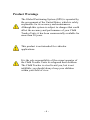
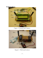
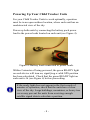
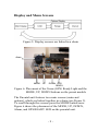
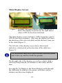
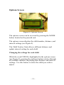
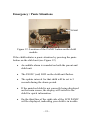
Child Tracker System Owners Manual & Reference English 273 Assignment No.5 User Manual Submitted to Joe Benge, Mel Dundas and Wayne Mayes June 16, 2006 Software Version 1.0 © 2006 Child Tracker Incorporated Camosun College Interurban Campus 4461 Interurban Rd Victoria BC, V9E 2C1 Tel: 250-370-3000 Web: www.camosun.bc.ca John Caruana [email protected] Tel: 250-812-0926 Douglas Irvine [email protected] Tel: 250-923-8984 Christopher Cheng [email protected] Tel: 250-216-4537 Matthew Quenet [email protected] Tel: 250-888-7208 -2- Table of Contents Package Contents Page 4 How to Use this Guide Page 4 GPS & You Page 5 Product Warnings Page 6 Unit Features Page 7 Powering up the Units Page 8 Displays & Menus Page 9 Main Display Page 10 Options Display Page 11 Child Out-of-Range Page 13 Panic Situation Page 15 Glossary of Terms Page 17 Acknowledgments Page 18 -3- Thank You! Thank you for choosing the Child Tracker Unit, the first easy-to-use GPS based outdoor child finder! Your child’s safety is paramount to our corporate policy. We hope that you and your family enjoy a peace of mind by using this device. To get the most from your new unit, take the time to read through this owner’s manual in order to understand the operating features. Before getting started with your Child Tracker, check to see that your package includes the following items: • Child Tracker Parental Unit (see Figure 2) • Child Unit (see Figure 3) • Owner’s Manual • Two Battery Packs How to use this Guide Throughout this manual, you will encounter several important icons, representing: Useful or troubleshooting tips. Precautionary warnings. -4- Global Positioning Satellites & You The Child Tracking Unit relies on the Global Positioning System. GPS is a system of 24 satellites (see Figure 1), which circle the earth and transmit information to the earth. The Child Tracker Units must continuously “see” at least three of these satellites to calculate your child’s position. The Child Tracker Units can determine the distance and position of any GPS satellite, and use this information to compute your position and your child’s position. Once you power up the unit, it will compute a position within a few moments. We will show you how to initialize your new Child Tracker GPS later on in this guide. Figure 1: 24 GPS satellites orbiting the Earth. -5- Product Warnings The Global Positioning System (GPS) is operated by the government of the United States, which is solely responsible for its accuracy and maintenance. Although this system is subject to changes that could affect the accuracy and performance of your Child Tracker Units, it has been commercially available for more than 20 years. This product is not intended for vehicular applications. It is the sole responsibility of the owner/operator of the Child Tracker Units to safeguard their children. The Child Tracker is a tool to aid you, but is not infallible; you should always keep your children within your field of view. -6- Unit Features GPS Ready LED GPS Antenna GPS Receiver RF Antenna Graphical LCD Battery Pack Figure 2: Parental unit features RF Antenna GPS Receiver GPS Antenna Power On Panic GPS Ready Battery Pack Figure 3: Child unit features -7- Powering Up Your Child Tracker Units For your Child Tracker Units to work optimally, operation must be in an open outdoor location, where each unit has an unobstructed view of the sky. Power up both units by connecting the battery pack power lead to the power leads located on each unit (see Figure 4). Figure 4: Battery leads connected to power leads. Within 2 minutes of being powered, the green READY light on each device will turn on, signifying a valid GPS position has been calculated. Check that the green READY light on each unit is lit (see Figure 6) before proceeding. If the ready light does not appear in the first couple of minutes of operation, check that the units have a clear view of the sky. Large buildings, mountains, or heavy tree cover may prevent the units from receiving enough satellite signal data to calculate a position. -8- Display and Menu Screens Figure 5: Display screens are linked in a chain Alarm MODE UP DOWN GPS READY Figure 6: Placement of the Green (GPS) Ready Light and the MODE, UP, DOWN buttons on the parent module The Parental unit features two main screens (main and options), which are linked together in a chain (see Figure 5). To scroll through the screens press the MODE button once. Figure 6 shows the placement of the MODE, UP, DOWN, Alarm, and GPS READY LED on the parental unit. -9- Main Display Screen Figure 7: Parental Unit main display screen; on the left it shows the display on power up, the right shows when a GPS fix has been sustained The main display screen will show “GPS Acquiring” until a GPS fix has been sustained. After that the display will show the direction of the selected child, and the distance from you to the child (Figure 7). The left side of the display screen shows directional indicators, which point in the direction of the child (see Figure 7). The directional indicator is most accurate when the parent unit is face up, and level with the ground. On the right side of the display you will see which child is currently being tracked, the distance to that child, and the time. Pressing the Up Button or the Down Button scrolls through the child units available to the parent, with their relative distance and direction displayed. - 10 - Options Screen Figure 8: Options Screen The options screen can be accessed by pressing the MODE button located on the parental unit. The options screen displays the child number, distance, and interval settings (see Figure 8). The Child Tracker Units allow a different distance and update interval setting for each child. Changing the settings for each child While the word CHILD is highlighted in the options screen (see Figure 8), pressing the up/down buttons rotates through all available children, displaying their distance and interval settings. Use this feature to select the child you wish to adjust. - 11 - Changing the allowable Distance for each child Figure 9: Distance setting for each child Select the child you wish to adjust (Figure 8), and then press the MODE button to highlight the word RANGE (Figure 9). While the word RANGE is highlighted, pressing the up/down buttons will change the allowable range for that child, between 10 and 150 meters, in 5-meter increments. Longer distances are more accurate when using GPS. Changing the update Interval for each child Figure 10: Interval setting for each child - 12 - Adjusting the interval setting adjusts the time between updating the last known position of the child. Select the child you wish to adjust (Figure 8) and then press the MODE button twice, until the word INTRVL is highlighted (see Figure 10). Pressing the UP/DOWN buttons will adjust this option. Intervals of 5 to 30 seconds (in 5 second increments) may be set. Shorter intervals allow the main display screen to be updated more rapidly; however this shortens the battery life. Five seconds is the suggested update interval. Press the MODE button to return to the main display screen. Child Out-of-Range Situation Figure 11: Displaying the information for a child out of range - 13 - If a child being tracked strays beyond the desired range: (Figure 11) An audible alarm will sound on the parental unit, alerting the parent of the situation. If the out-of-range child is not currently being displayed on the main screen, the display will switch to that child for quick information. On the third line, the right side of the LCD will display TOO-FAR, indicating the child has strayed beyond the set distance. The update interval for that child will be set to 5 seconds during the alarm period. The alarm will disarm when the child or yourself is back within distance of the set range. - 14 - Emergency / Panic Situations PANIC Figure 12: Location of the PANIC button on the child module If the child initiates a panic situation by pressing the panic button on the child unit (see Figure 12) An audible alarm is sounded on both the parent and child unit. The PANIC (red) LED on the child unit flashes. The update interval for that child will be set to 5 seconds during the alarm period. If the panicked child is not currently being displayed on the main screen, the display will switch to the child for quick information. On the third line of the right side of the LCD PANIC will be displayed, indicating your child is in trouble. - 15 - To disable the panic alarm on both units press the panic button on the child’s unit. - 16 - Glossary of Terms Panic Situation: A panic situation is when your child has pressed the panic button on the child module. This should be used to alert the parent that your child needs your immediate attention. Child-out-of-Range: Once you have set a range for a child the GPS will continually check to make sure that your child is within that distance. If your child goes beyond that distance, the Child out of Range alarm will sound. This should alert the parent to go retrieve his/her child. Compass Directions: These arrows on the screen point in the direction of your child. The arrows are in the shape of a cone, and your child should be located in the direction that the cone points at the specified distance. Update Interval: This is the time it takes to get new data and update the display as to the location of your child and its direction. The recommended setting is 5 seconds. LED Light Emitting Diodes are used to alert the user to the modules condition, these small lights have different colors: Red is for panic Green is for GPS online Blue is for power on - 17 - Acknowledgments This project would not have been possible without the dedication of Mel & Wayne and the resources provided to us by Camosun College. We would also like to thank US Global Sat for providing us with free GPS samples, along with Hitachi Metals America, Ltd. for providing us with free samples of their digital compass (HM55B). What to tell your child This product is designed for tracking people of all ages. To get the most out of the Child Tracker, ensure you talk with your family so everyone understands how to use this device, and what do in emergency situations. - 18 -