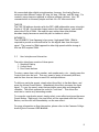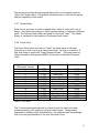
1
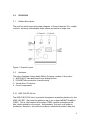
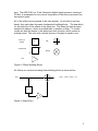
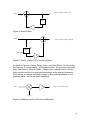
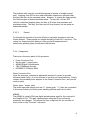
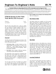
ELEX 290
Camosun College
Audio Effects Processor
Prepared for
Godfried Pimlott
Joe Benge
Prepared by
Darryl Gamroth
Simon Tipler
March 10, 2001
March 16, 2001
Godfried Pimlott
Joe Benge
Camosun College
Dear Mr. Pimlott and Mr. Benge
I am enclosing our report Camosun College Audio Effects Processor as
requested.
Sincerely
Simon Tipler
Enc
ii
Executive Summary
The Camosun College Audio Effects Processor allows the User to easily add
“effects” to their music or clean a noisy signal. With a simple User Interface
and many effects with extreme customization features, this processor
surpasses the competition.
Using a DSP processor, all mathematical calculations are very quick to render
pristine sound quality. Also, the User Interface is ridiculously simple with a
clear graphical display and a single Control Knob with push button. This knob
controls all variables and navigation allowing the musician to make quick
changes and get back to enjoying their music.
iii
Table of Contents
1.0
CONCEPT............................................................................1
1.1
Understanding this Report.....................................................1
1.2
Background ......................................................................1
2.0
DISCUSSION .........................................................................2
2.1
Product Description ............................................................2
2.2
Hardware.........................................................................2
2.2.1
ADSP-2181 EZ Kit Lite.....................................................2
2.2.2
PIC Microcontroller........................................................5
2.2.3
Input / Output devices ...................................................6
2.2.3.1
LCD Display............................................................6
2.2.3.2
Control Knob ..........................................................7
2.2.3.3
Presets.................................................................8
2.2.4
Components ................................................................8
2.3
User Interface and Interaction................................................9
2.4
Effects .......................................................................... 10
2.4.1
Passthru................................................................... 10
2.4.2
Dirty Distortion .......................................................... 10
2.4.3
Cool Chorus............................................................... 10
2.4.4
Rad Reverb ............................................................... 10
2.4.5
Phun Phasor .............................................................. 10
2.4.6
Funky Flange ............................................................. 10
2.4.7
Demon Delay ............................................................. 11
2.4.8
Power Pitch .............................................................. 11
2.4.9
Fierce Filter .............................................................. 12
2.5
Cost ............................................................................. 13
3.0
CONCLUSION...................................................................... 13
4.0
GLOSSARY of TERMS ............................................................. 14
5.0
REFERENCES ...................................................................... 16
6.0
APPENDICES ...................................................................... 17
6.1
Schematic ...................................................................... 17
6.2
Top Layer PCB ................................................................. 18
6.3
Bottom Layer PCB............................................................. 19
6.4
User Interface Top Level State Machine................................... 20
6.5
User Interface Controller Source Code .................................... 21
6.6
DSP Source Code .............................................................. 22
iv
List of Figures
Figure
Figure
Figure
Figure
Figure
Figure
Figure
Figure
1:
2:
3:
4:
5:
6:
7:
8:
Physical Layout .................................................................2
Effects Building Blocks ........................................................3
Delay Effect.....................................................................3
Reverb Effect ...................................................................4
Chorus, Flange, Pitch, and Chord Effect ...................................4
Modulator used for Vibrato and Distortion .................................4
Phasor using a variable frequency notch filter ............................5
Direction state machine for the Control Knob .............................7
List of Tables
Table 1: The scale ....................................................................... 11
v
Camosun College Audio Effects Processor
1.0
CONCEPT
This report will introduce the reader to the Camosun College Audio Effects
Processor including descriptions of the unit, input/output requirements, User
Interface and controls, and the effects.
1.1
Understanding this Report
The simple menus system accesses all of the options for this system. To
further understand the navigation system, read the Camosun College Audio
Effects Processor USER MANUAL. When this report describes the use of each
effect, we assume the reader is familiar with the basics of musical
terminology. The Glossary of Terms includes definitions of most terms in this
report.
1.2
Background
Guitar effect processors are commonplace in the music industry with nearly all
guitarists using some type of guitar pedal to alter the sound from their guitar.
Since the 60’s, guitar pedals have improved with better sounds and more
options for the musician. Leaders in this huge industry include BOSS, Digitech,
Ibanez, and others. Currently, multi-effect pedals have hundreds of effects
with fantastic customizability, but their price is beyond the amateur guitarist’s
budget.
That is not the only problem. What about people who play the flute, oboe, or
saxophone? What about DJ’s using turntables? There are many instruments,
beyond guitar, that can use an effects processor. The User only requires only a
microphone and preamp. The Camosun College Audio Effects Processor
improves the sound of any instrument.
1
2.0
DISCUSSION
2.1
Product Description
This unit has stereo input and output channels, a Power Connector Port, simple
controls, and many customizable audio effects enclosed in a beige case.
Figure 1: Physical Layout
2.2
Hardware
The entire Camosun College Audio Effects Processor consists of four parts:
1. ADSP-2181 EZ Lab demo board from Analog Devices
2. PIC16F877 Microcontroller from Microchip
3. Various User I/O devices
4. Control components
2.2.1 ADSP-2181 EZ Kit Lite
The ADSP-2181 EZ Kit Lite is a powerful inexpensive evaluation platform for the
ADSP-2181 DSP. We chose this platform due to its on board AD1847 SoundPort
CODEC. This is a full duplex 16 bit stereo CODEC capable of sampling at 48
kHz, ideally suited for our project. Unfortunately, this part is no longer in
production; therefore, we could not produce a commercial product using this
2
part. The ADSP-2181 is a 16 bit fixed point digital signal processor running at
33 MHz, it is adequate for our current incarnation of the effects processor but
has several quirks.
All of the effects are processed in the time domain. As all effects are time
based, they each share the same fundamental building blocks. The base block
for the majority of the effects is the delay line. The delay line puts an input
sample into memory, which is recalled later to produce a delay. To create
reverb we feed the output of the delay back into its input, which causes an
echoing sound. This echo will continue forever if the gain is equal to one.
Delay by D
samples
Add
Z-D
Variable Delay
Multiply
Gain
x
Figure 2: Effects Building Blocks
All effects are constructed using these building blocks as shown below:
y (n) = x(n) + ax(n − d )
x(n)
Z-d
a
Figure 3: Delay Effect
3
y (n) = x(n) + ay (n − d )
x(n)
Z-d
a
Figure 4: Reverb Effect
y (n) = x(n) + ax (n − d (n))
x(n)
Z-d(n)
d (n)
a
Figure 5: Chorus, Flange, Pitch, and Chord Effect
As shown in Figure 5: Chorus, Flange, Pitch, and Chord Effect, we can modify
the function d (n) as we see fit. In the chorus effect, the processor varies the
delay from 20ms to 50ms at 0.25Hz. Flange is just a special case of chorus;
delay varies from 0ms to a user specified amount and a selected frequency.
Pitch scaling is a similar technique, except to drop and add samples to the
playback buffer, we use saw tooth waveform.
x(n)
a
y ( n) = a × x( n) × f ( n)
f (n)
Figure 6: Modulator used for Vibrato and Distortion
4
Distortion is achieved by modulating the input signal with either a sinusoid or a
saw tooth wave. The output signal can be saturated by adjusting the gain.
y (n)
x(n)
H(z)
a
Figure 7: Phasor using a variable frequency notch filter
To implement phasor, the input signal is mixed with itself passed through a
notch filter. This causes a phase shift in the output signal.
2.2.2 PIC Microcontroller
The PIC Microcontroller from Microchip controls all User input and transmits all
changes in data to the ADSP EZ Lab demo board. The User Interface uses the
PIC16F877 for its multiple serial communication ports, speed, many
input/output ports, built in timers, and availability of optimized C compilers.
For this project, we use the Serial Peripheral Interface (SPI) to communicate
with a digital potentiometer, the Analog Devices AD8400, discussed in the
“Control Components” section.
The PIC also runs at the maximum speed of 20MHz. By running at this speed,
the PIC can quickly compute calculations, rapidly transmit data, and control
many devices. Since current consumption is not a variable in this project
because of the required power adapter, this warrants running at a faster
speed.
Since this PIC16F877 has 33 I/O pins, there are enough data lines for the
parallel memory write, control, User input, and chip selection. Originally,
there were not enough data lines for communication. To resolve this problem,
the Toshiba TC74HC595 (SPI 8-bit shift register) could add eight more output
lines. This device is incredibly useful because it only requires a chip select and
the SPI data and clock lines, which the digital potentiometer already uses.
After much rearrangement, and a change in a major component, this chip was
no longer necessary.
5
Another purpose for the PIC Microcontroller is the “Interrupt on change”
feature on PORT B for the Control Knob. We tested this feature; however,
polling proved to be more effective. Using the “Interrupt on change” missed
occasional step rotations, but polling never missed any changes.
To compose code for the PIC16F877, we used the PCM C Compiler. This
compiler is extremely efficient, and it is simple to use for writing strings of
data to a device. To fit large programs, this compiler spends most of the
compiling process rearranging code to fill banks on the PIC. Most compilers for
PIC do not rearrange segments for optimum banking. To make compiled code
more efficient, the complier optimizes both delays and complicated math
routines.
Another feature of the PIC processor family is the built in timers. These allow
interrupts to occur determined by the programmer. The purpose for these
timers in this project is to determine “timeouts” when waiting too long for a
particular device to respond and to determine the rotation speed of the
Control Knob.
2.2.3 Input / Output devices
The Input / Output devices consists of three groups:
1. LCD Display
2. Control Knob
3. Preset Buttons
Please refer to section 2.3, User Interface and Interaction, for more
information regarding the use of the Camosun College Audio Effects Processor.
2.2.3.1
LCD Display
The LCD for this project is the Optrex DMF50834 with a built using the NEC
upd16435 controller distributed by Apollo Displays (www.apollodisplays.com).
This product is ideal for this project for its multiple options and fast speed.
Some of the built in functions are:
Reverse Line
Magnification (Double width, double height, or both double width and
double height)
Blinking character
Cursor
Backlight
At the beginning of the project, the options were unknown; this made this LCD
particularly advantageous. We considered using the backlight function, but
6
abandoned it because of its extreme sensitivity to small changes in voltage. In
addition, the LCD for this project was inexpensive because of a broken
backlight.
To signify a selected item, we used the reverse line function. Our group felt
this would unmistakably designate a selected item.
The Graphical Display shows the User the vertical menu system and all submenus. This system is unbelievably User-friendly to navigate and edit settings.
A reversed line designates the currently selected item on the LCD.
Depending on the lighting in the environment, the User is able to digitally set
the contrast in the Contrast menu item (see AD8400 in the Control
Components).
2.2.3.2
Control Knob
To simplify all User-interaction, the knob with integral push button controls the
entire system. We chose a 32 detent Grayhill 61C11-01-08-02. The detents
provide the User feedback to acknowledge single steps. There are only three
wires to communicate to the PIC controller; two wires for the direction of
rotation and the other wire provides the signal for the push button.
Figure 8: Direction state machine for the Control Knob
Since the PIC recognizes each step of the Control Knob, it is simple to
determine the speed and direction of the rotation. Using one of the PIC’s
built-in timers, we determined that a change within 190ms defines “fast”
rotation. Any changes that take longer than this define as “slow” or “single
step” rotations. We call this process, “velocity-controlled stepping” where fast
rotations result in bigger changes in setting a variable. Steps for a fast rotation
are groups of ten. With a 32 step knob, a full byte change is 256/(10*32) = 0.8
of a full rotation. We chose groups of ten because this is the greatest change
possible for one to easily rotate the knob.
7
The problem with velocity-controlled stepping is looping a variable around
zero. Stepping from 255 to zero (and backwards) seems more efficient than
blocking the User at the maximum value. However, if turning the knob quickly,
the User may pass a desired maximum value. To stop this, we turn OFF
velocity-controlled stepping when the User is 20 steps from minimum and
maximum values. This way, the User can still loop around, but not make an
undesired mistake.
2.2.3.3
Presets
To allocate the musician’s favorite effects to particular presets we use four
Preset Buttons. These presets are simple Normally Closed (N/C) contacts. The
reason for these particular buttons is they are both inexpensive and
esthetically pleasing (they already have red buttons).
2.2.4 Components
There are a few more parts of this processor:
Power Connector Port
Stereo input / output jacks
AD8400 Digital Potentiometer
74HC138 Address Decoder
K6T4008C1V 512kbyte SRAM
Power Connector Port
Since the processor consumes a substantial amount of current to provide
ultimate sound clarity, it is not efficient to run this unit from batteries. Simply
connect the included power adapter to the Power Connector Port, and you are
ready to play!
Stereo input / output jacks
The audio input and output ports are ¼” stereo jacks. ¼” jacks are a standard
in the music industry for their power handling abilities and cost of cable.
AD8400
The AD8400 is a single 256 step digital potentiometer used for the contrast of
the Graphical LCD. This part communicates using the SPI port allowing
extremely fast changes. This allows the User to digitally set the contrast of
their screen in the “Contrast” sub-menu.
8
We researched other digital potentiometers; however, the Analog Devices
series provides different ranges (32 step, 64 step, 128 step, and 256 step). For
contrast, many steps are required to achieve optimum contrast. Also, SPI
communication is extremely simple and fast for a PIC Microcontroller.
74HC138
The 74HC138 address decoder splits the DSP’s 4MB addressable space into eight
blocks of 512 kB. One decoder output selects the flash memory, and another
selects the 512k of SRAM. We used this part rather than other address
decoders simply because we used this part in studies at school.
K6T4008C1V
The K6T4008C1V from Samsung is low power, high speed SRAM. SRAM is
required to provide a sufficient buffer for the digital data from the input
signal. The reason for SRAM opposed to other high speed volatile storage is
that our DSP requires SRAM.
2.3
User Interface and Interaction
The entire interfaces consists of three parts:
1. Graphical Display
2. Control Knob
3. Four Preset buttons
To enter a menu item, edit a number, exit number entry, etc., simply press the
Control Knob into the unit. This way, speed of entry is extremely efficient,
and the User does not have to search for multiple buttons.
To define a particular preset, simply select the effect in the Main Menu, and
press the chosen Preset Button. Immediately this effect processes the input
signal. To vary the sound, enter that particular menu item and change the
variables. The effect updates the sound in “real time”. This allows the
musician to create very interesting sounds.
To overwrite a particular preset, simply select a new effect and press the same
Preset Button. Right away, the new effect will be associated with that Preset
Button, and the unit will immediately run the new effect.
For more information on User Interaction, please refer to the Camosun College
Audio Effects Processor USER MANUAL.
9
2.4
Effects
2.4.1 Passthru
Simply outputs the input signal with absolutely no processing on the sound.
This is called a “Dry Signal”.
2.4.2 Dirty Distortion
By increasing the amplitude of the input signal, eventually the signal will
“clip”. Clipping is the process by which an AC signal increases past the
stability point. The result is many high frequency components also known as
“noise”. The User has full control over the level of noise.
2.4.3 Cool Chorus
The Chorus effect allows the user to hear multiple instances of the input signal
when each instance synchronizes with the others, except for small variations in
their strength and timing. This means that one vocalist can sound up to three
people singing the same thing. The User controls the number of “voices” heard
with a maximum of three due to program space restrictions.
2.4.4 Rad Reverb
Reverb is simply a Comb Filter. This effect occurs when a sound wave bounces
off walls of a listening space, but has an interesting effect when there are
multiple reflections.
2.4.5 Phun Phasor
Phasing or phase shifting passes the signal through a narrow notch filter and
combines a proportion of the filter’s output with the direct sound. To create a
weird effect, the centre frequency of the notch filter varies in a controlled
manner. The User sets this variable in the Phun Phasor Sub-Menu.
2.4.6 Funky Flange
10
The process of periodically varying the delay with a low frequency (such as
1Hz) is the Flange effect. This product allows the User to set both the period
and the frequency of this sound.
2.4.7 Demon Delay
Delay for our processor is really a tapped delay, which is really just a set of
delays. Our system provides up to three separate delays of a signal at different
gains. The User sets both delays and gains for the three “taps”. This allows
plenty of variables for the musician to customize their sound.
2.4.8 Power Pitch
The Power Pitch allows the User to “bend” the input signal in half step
intervals up to one octave up or one octave down. An octave consists of 12
half step tones to create the “Equal Tempered Scale”. The scale based on
fifths proposed by Pythagoreas (600BC) is the basis of the Equal Tempered
Scale.
Equal Tempered Scale
(Chromatic Version)
C
C#
D
D#
E
F
F#
G
G#
A
A#
B
C
Ratio
Interval Name
Just Interval
1.0000
1.0595
1.1225
1.1892
1.2599
1.3348
1.4142
1.4983
1.5874
1.6818
1.7818
1.8877
2.0000
Unison
Half Step
Whole Step
Minor Third
Major Third
Perfect Fourth
Diminished Fifth
Perfect Fifth
Minor Sixth
Major Sixth
Minor Seventh
Major Seventh
Octave
1.0000
1.0667
1.1250
1.2000
1.2500
1.3333
1.4063 or 1.4222
1.5000
1.6000
1.6667
1.8000
1.8750
2.0000
Table 1: The scale
The 12-tone equal tempered scale is a natural scale for electronic music
systems because of the simplicity of equal valued steps. Though nearly
impossible to audibly notice any difference, the musician must acknowledge
this is only an approximation of the true Just Major Scale.
11
2.4.9 Fierce Filter
To reduce high frequency noise from a particular input instrument, the Fierce
Filter allows the user to remove high frequencies. The User is also able to set
the cut-off frequency.
12
2.5
Cost
DSP Board
PIC
SRAM
Flash
PCB
Connectors
LCD
Knob
Buttons
Case
Misc
$132.00
$ 15.00
$ 32.00
$ 10.00
$ 10.00
$ 15.00
$ 50.00
$ 32.00
$ 10.00
$ 22.00
$ 20.00
Sub Total
Provided
Total
$348.00
($167.00)
$181.00
Provided
Provided
Free
Provided
We completed this project significantly under budget. This is due to most of
the expensive components supplied by the College.
3.0
CONCLUSION
The Camosun College Audio Effects Processor provides the musician with
several advantages over many other similar products:
Line input! Not only for guitar
Extremely simple User Interface with clear LCD display and few buttons
Future expandability
This chief disadvantage of this product is only in the number of effects. Future
expansions of this product will allow for multiple inputs and more effects.
13
4.0
GLOSSARY of TERMS
HARDWARE
CODEC
Hardware that performs analog to digital and digital
to analog conversion. Includes signal conditioning
circuitry
Control Knob – large knob below the LCD. This is the main input
device for the User.
Control Knob Button – asserts when the Control Knob is pushed into
the unit
Control Knob Rotation – turning the Control Knob
Full Duplex
The ability to record and playback simultaneously
Input Device
Any audio source with a LINE output
LCD
The text display screen
Output Device
Any audio output device with a line input (ie
Amplifier)
Power Connector Port
Requires minimum 7V at 200mA power adapter
Preset Buttons
Four red buttons to allocate particular effects to
particular Presets
MENU SYSTEM
Main Menu
The vertical list of particular options and effects.
Sub-Menu
The options for a particular item in the Main Menu.
Sub-Menus are only for items containing options or
information.
AUDIO TERMINOLOGY
Clip, Clipping
overload, severe distortion
14
dB (decibel)
a unit of measurement, ratio of two voltages (dB =
20log(V1/V2))
Dry Signal
no processing of the input signal
Filter
device or program for adding or removing part of a
frequency bandwidth
Line Signal
amplified signal within 100mV peak to peak
produced by sound cards, turntables, etc.
Mic (Microphone) Signal
signal within 20mV peak to peak produced by
guitars, microphones, etc.
Wet Signal
signal with effects added
15
5.0
REFERENCES
1. Analog Devices. ADSP-2100 Family – EZ-KIT Lite Reference Manual.
Norwood, MA, 1995.
2. Analog Devices. ADSP-2100 Family – EZ-KIT Lite Evaluation Platform Data
Sheet. Norwood, MA, 1998.
3. Behringer International. DX500 Pro Mixer USER’S MANUAL. Hanns-MartinSchleyer-Straße. D-47877 Willich, Műnchnëide ||, September 1998.
4. Hutchins, Bernie. Music for Electronic Engineers. Electronotes. Ithaca,
New York, July 1975.
5. Orfanidis, Sophocles J. Introduction to Signal Processing. Prentice-Hall
Signal Processing Series. Upper Saddle River, New Jersey, 1996
16
6.0
6.1
APPENDICES
Schematic
1
2
3
4
6
5
Y1
4MHz
+5V
R1
1kOhm
C4
0.1uF
C1
0.1uF
C3
18pF
D
11
32
C2
18pF
+5V
D
R2-5
1kOhm sim
J1
PRESETS
+5V
12
31
7
5
3
1
8
6
4
2
C
14
15 IAD0
16 IAD1
17 IAD2
18 IAD3
23 IAD4
24 IAD5
25 IAD6
26 IAD7
19 IAD8
20 IAD9
21 IAD10
22 IAD11
27 IAD12
28 IAD13
29 IAD14
30 IAD15
10
!CS_LCD
PIC16F874-20/P(40)
C8+5V
OSC1/CLKIN OSC2/CLKOUT
MCLR/VPPRC0/T1OSO/T1CKI
RA0
RC1/T1OSI/CCP2
RA1
RC2/CCP1
RA2
RC3/SCK/SCL
RA3
RC4/SDI/SDA
RA4/T0CKI
RC5/SDO
RA5/SS
RC6/TX/CK
RB0/INT
RC7/RX/DT
RB1
RD0/PSP0
RB2
RD1/PSP1
RB3
RD2/PSP2
RB4
RD3/PSP3
RB5
RD4/PSP4
RB6
RD5/PSP5
RB7
RD6/PSP6
RE0/RD//AN5
RD7/PSP7
RE1/WR/AN6 RE2/CS/AN7
VSS
VSS
13
1
!IWR 2
!IACK3
IAL 4
!IS 5
6
!IRD 7
PRESET0
33
PRESET1
34
PRESET2
35
36
PRESET3
37
38
39
!IRQL0 40
!DSPRESET8
9
+5V
VDD
VDD
U1
LCD_RS
LCD1
!CS_LCD
!IRD
!IWR
+5V
Vdrive
R6R7R8
1kOhm
0.1uF
U2
+5V
1
2
!DPOT_CS 3
4
SW1
6
5
4
3
2
1
V++
OUTA
OUTB
PB SW2
PB SW1
GND
6
5
4
3
2
1
OUTA
OUTB
SW2
B1 CLK
GNDVDD
!CS W1
SDI A1
5
6
7
8
J3
A0
A2
A4
A6
A8
A10
A12
U5
+5V
16
A
B
C
Y0
Y1
Y2
Y3
G1
Y4
G2A Y5
G2B Y6
Y7
SN74LS138
VCCGND
15 !FLASH_CS
14 !SRAM_CS
13
12
11
10
9
7
8
C5
+5V
D0
D1
D2
D3
D4
D5
D6
D7
A
22
!FLASH_CS
CE
!RD
24
OE
31
WE
1
VPP
28F010
13 D8
14 D9
15 D10
17 D11
18 D12
19 D13
20 D14
21 D15
U4
A012
A111
A210
A3 9
A4 8
A5 7
A6 6
A7 5
A827
A926
23
A10
25
A11
A124
28
A13
A143
31
A15
A162
30
A17
A181
A0
A1
A2
A3
A4
A5
A6
A7
A8
A9
A10
A11
A12
A13
A14
A15
A16
A17
A18
22
!SRAM_CS
!CS
24
!RD
!OE
29
!WR
!WE
VCC
VCC
A0
A1
A2
A3
A4
A5
A6
A7
A8
A9
A10
A11
A12
A13
A14
A15
A16
GND
0.1uF
C7
0.1uF
U3
A012
A111
A210
A3 9
A4 8
A5 7
A6 6
A7 5
A827
A926
23
A10
25
A11
A124
28
A13
29
A14
A153
A162
D0
D1
D2
D3
D4
D5
D6
D7
13 D8
14 D9
15 D10
17 D11
18 D12
19 D13
20 D14
21 D15
D8
D10
D12
D14
A14
A16
A18
A20
!WR
1
3
5
7
9
11
13
15
17
19
21
23
25
27
29
31
33
35
37
39
41
43
45
47
49
C
J2
A1
A3
A5
A7
A9
A11
A13
2
4
6
8
10
12
14
16
18
20
22
24
26
28
30
32
34
36
38
40
42
44
46
48
50
1
3
5
7
9
11
13
15
17
19
21
D9
23
D11
25
D13
27
D15
29
A15
31
A17
33
A19
35
!DSPRESET
A21
37
!RD
39
!BMS
41
43
45
+5V
47
49
IAD1
IAD3
IAD5
IAD7
IAD9
IAD11
IAD13
IAD15
!IACK
!IS
!IRD
+5V HEADER 25X2
2
4
6
8
10
12
14
16
18
20
22
24
26
28
30
32
34
36
38
40
42
44
46
48
50
IAD0
IAD2
IAD4
IAD6
IAD8
IAD10
IAD12
IAD14
B
IAL
!IWR
!IRQL0
HEADER 25X2
A
GND
C6
0.1uF
32
+5V
32
+5V
A19 1
A20 2
A21 3
+5V
6
!BMS 4
5
01 !CS_LCD
02 LCD_RS
03 !LCD_RD
04 !LCD_WR
05 D0
06 D1
07 D2
08 D3
09 D4
10 D5
11 D6
12 D7
13 !BUSY
14 !RESET
15 SCR
16 V+
17 GND
18 Vdrive
19 GND
20 Vbackligh
AD8400
Optical Switch
B
1
2
3
4
5
6
7
8
9
10
11
12
13
14
15
16
17
18
19
20
SupaDupa Audio Processor
Title
16
16
K6T4008C1B
Size
Number
Revision
B
Date:
File:
1
2
3
4
5
21-Mar-2001
Sheet of
C:\Documents and Settings\dgamroth\My
Drawn By:
Documents\Effects Processo
6
17
6.2
Top Layer PCB
18
6.3
Bottom Layer PCB
19
6.4
User Interface Top Level State Machine
20
6.5
User Interface Controller Source Code
See hard copy.
21
6.6
DSP Source Code
See hard copy.
22