1
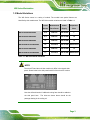
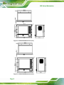
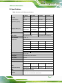
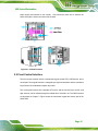
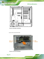
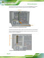
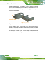
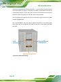
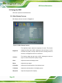
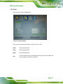
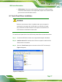
WS Series Workstation MODEL: WS Series 8-slot/10-slot or microATX LCD Workstation RoHS Compliant, IP 65 Protection User Manual Page i Rev. 1.00 – 9 July, 2013 WS Series Workstation Revision Date Version Changes 9 July, 2013 2.00 Updated for R20 version March, 2006 1.00 Initial release Page ii WS Series Workstation Copyright COPYRIGHT NOTICE The information in this document is subject to change without prior notice in order to improve reliability, design and function and does not represent a commitment on the part of the manufacturer. In no event will the manufacturer be liable for direct, indirect, special, incidental, or consequential damages arising out of the use or inability to use the product or documentation, even if advised of the possibility of such damages. This document contains proprietary information protected by copyright. All rights are reserved. No part of this manual may be reproduced by any mechanical, electronic, or other means in any form without prior written permission of the manufacturer. TRADEMARKS All registered trademarks and product names mentioned herein are used for identification purposes only and may be trademarks and/or registered trademarks of their respective owners. Page iii WS Series Workstation Table of Contents 1 INTRODUCTION.......................................................................................................... 1 0H 97H 1.1 OVERVIEW.................................................................................................................. 2 1.2 MODEL VARIATIONS ................................................................................................... 3 1.3 SYSTEM ARCHITECTURE ............................................................................................ 4 1.4 DIMENSIONS ............................................................................................................... 4 1.5 SPECIFICATIONS ......................................................................................................... 7 1.6 RECOMMENDED BACKPLANES ................................................................................... 8 1.7 RECOMMENDED POWER SUPPLIES.............................................................................. 8 1.8 AV-6650 AD BOARD OVERVIEW ................................................................................ 9 1.8.1 AV-6650 Peripheral Interface Connectors....................................................... 10 1.8.2 AV-6650 Rear Panel Connectors ..................................................................... 10 1H 98H 2H 9H 3H 10H 4H 10H 5H 102H 6H 103H 7H 104H 8H 105H 9H 106H 10H 107H 2 INSTALLATION ..........................................................................................................11 1H 108H 2.1 ANTI-STATIC PRECAUTIONS ...................................................................................... 12 2.2 INSTALLATION PRECAUTIONS ................................................................................... 12 2.3 UNPACKING .............................................................................................................. 13 2.3.1 Unpacking Procedure ...................................................................................... 13 2.3.2 Packing List ..................................................................................................... 14 2.4 AIRFLOW CONSIDERATION ....................................................................................... 14 2.5 FRONT CONTROL INTERFACE.................................................................................... 15 12H 109H 13H 10H 14H 1H 15H 12H 16H 13H 17H 14H 18H 15H 2.6 WORKSTATION INSTALLATION .................................................................................. 16 19H 16H 2.6.1 Accessing the Interior of the Workstation ........................................................ 16 2.6.2 Installing CPU Cards, Backplane, or Micro-ATX Main Board....................... 17 2.6.3 Installing Peripheral Devices .......................................................................... 21 2.7 CABLING .................................................................................................................. 25 2.7.1 Internal Cabling............................................................................................... 25 2.7.2 External Cabling.............................................................................................. 25 2.8 MOUNTING THE WORKSTATION ................................................................................ 27 2.8.1 Panel Mounting................................................................................................ 27 2.8.2 Rack Mounting ................................................................................................. 28 20H 17H 21H 18H 2H 19H 23H 120H 24H 12H 25H 12H 26H 123H 27H 124H 28H 125H Page iv WS Series Workstation 3 ON-SCREEN-DISPLAY (OSD) CONTROLS .......................................................... 29 29H 126H 3.1 USER MODE OSD STRUCTURE ................................................................................. 30 3.1.1 OSD Buttons..................................................................................................... 30 3.1.2 OSD Menu Structure ........................................................................................ 31 3.2 USING THE OSD....................................................................................................... 32 3.2.1 Main Display Features..................................................................................... 32 3.2.2 Color ................................................................................................................ 33 3.2.3 OSD Configurations......................................................................................... 34 30H 127H 31H 128H 32H 129H 3H 130H 34H 13H 35H 132H 36H 13H 4 SOFTWARE DRIVERS .............................................................................................. 35 37H 134H 4.1 INTRODUCTION......................................................................................................... 36 38H 135H 4.2 RS-232 OR USB TOUCH SCREEN ............................................................................. 36 4.3 TOUCH PANEL DRIVER INSTALLATION ...................................................................... 37 4.4 CHANGE THE TOUCH SCREEN INTERFACE ................................................................ 40 4.5 CALIBRATING THE TOUCH SCREEN ........................................................................... 40 39H 136H 40H 137H 41H 138H 42H 139H A SAFETY PRECAUTIONS ......................................................................................... 43 43H 140H A.1 SAFETY PRECAUTIONS ............................................................................................ 44 A.1.1 General Safety Precautions ............................................................................. 44 A.1.2 Anti-static Precautions .................................................................................... 45 A.1.3 Product Disposal ............................................................................................. 46 A.2 MAINTENANCE AND CLEANING PRECAUTIONS ........................................................ 46 A.2.1 Maintenance and Cleaning.............................................................................. 46 A.2.2 Cleaning Tools ................................................................................................. 47 4H 14H 45H 142H 46H 143H 47H 14H 48H 145H 49H 146H 50H 147H B HAZARDOUS MATERIALS DISCLOSURE ......................................................... 48 51H 148H B.1 HAZARDOUS MATERIALS DISCLOSURE TABLE FOR IPB PRODUCTS CERTIFIED AS ROHS COMPLIANT UNDER 2002/95/EC WITHOUT MERCURY ....................................... 49 52H 149H Page v WS Series Workstation List of Figures Figure 1-1: Modular Design ...........................................................................................................4 53H 150H Figure 1-2: WS-612GS Dimensions (mm).....................................................................................5 54H 15H Figure 1-3: WS-843GS Dimensions (mm).....................................................................................5 5H 152H Figure 1-4: WS-855GS Dimensions (mm).....................................................................................6 56H 153H Figure 1-5: WS-875GS Dimensions (mm).....................................................................................6 57H 154H Figure 1-6: AV-6650 AD Board Overview .....................................................................................9 58H 15H Figure 2-1: Airflow Direction .......................................................................................................15 59H 156H Figure 2-2: Keypad and Mouse Pad............................................................................................16 60H 157H Figure 2-3: Open the Rear Cover ................................................................................................17 61H 158H Figure 2-4: Backplane Installation ..............................................................................................18 62H 159H Figure 2-5: CPU Card Installation ...............................................................................................18 63H 160H Figure 2-6: Hold-down Clamps....................................................................................................19 64H 16H Figure 2-7: Installing the Longer Hold-down Clamp .................................................................20 65H 162H Figure 2-8: Installing the SBC Hold-down Clamp......................................................................20 6H 163H Figure 2-9: Installing the Card Clamp.........................................................................................21 67H 164H Figure 2-10: Drive Bay Locations................................................................................................22 68H 165H Figure 2-11: Screw Locations at the Chassis Bottom ..............................................................22 69H 16H Figure 2-12: Screw Locations at the Chassis Bottom ..............................................................23 70H 167H Figure 2-13: Power Supply Installation ......................................................................................24 71H 168H Figure 2-14: Side Panel Cabling..................................................................................................26 72H 169H Figure 2-15: Panel Mounting .......................................................................................................27 73H 170H Figure 2-16: Rack Mounting ........................................................................................................28 74H 17H Figure 3-1: OSD Control Buttons ................................................................................................30 75H 172H Figure 3-2: Main Display Features ..............................................................................................32 76H 173H Figure 3-3: Color Options ............................................................................................................33 7H 174H Figure 3-4: OSD Configurations Menu .......................................................................................34 78H 175H Figure 4-1: Setup Icon ..................................................................................................................37 79H 176H Figure 4-2: Welcome Screen .......................................................................................................38 80H 17H Figure 4-3: License Agreement ...................................................................................................38 81H 178H Figure 4-4: Initiate Install .............................................................................................................39 82H 179H Page vi WS Series Workstation Figure 4-5: Installation Starts ......................................................................................................39 83H 180H Figure 4-6: Finish Installation......................................................................................................40 84H 18H Figure 4-7: PenMount Monitor Icon ............................................................................................41 85H 182H Figure 4-8: PenMount Monitor Popup Menu ..............................................................................41 86H 183H Figure 4-9: Configuration Screen................................................................................................41 87H 184H Figure 4-10: Calibration Initiation Screen ..................................................................................42 8H 185H Figure 4-11: Calibration Screen ..................................................................................................42 89H 186H Page vii WS Series Workstation List of Tables Table 1-1: WS Series Model Variations ........................................................................................3 90H 187H Table 1-2: WS Series Specifications.............................................................................................8 91H 18H Table 1-3: WS Series Recommended Backplanes ......................................................................8 92H 189H Table 1-4: WS Series Recommended Power Supplies ...............................................................9 93H 190H Table 1-5: AV-6650 Peripheral Interface Connectors................................................................10 94H 19H Table 1-6: AV-6650 Rear Panel Connectors...............................................................................10 95H 192H Table 3-1: OSD Menus..................................................................................................................31 96H 193H Page viii WS Series Workstation Chapter 1 1 Introduction Page 1 WS Series Workstation 1.1 Overview The WS Series workstation is a member of IEI’s line of sophisticated LCD and chassis designs, and it has been improved to be RoHS compliant. The WS Series is equipped with a 10.4/12.1/15/17 inch TFT type color LCD. The LCD screen itself features an MTBF up to 50,000 hours. With exceptional brightness, wide-view-angles, and fast response performance, the series is ideal for a wide range of applications. The WS LCD workstation series supports resolutions up to 1280(H) X 1024(V) pixels with 260,000 colors. For resolutions of other models, please refer to the following discussions. The WS LCD workstations are designed to fit Industrial automation or any applications that require the capabilities of working under harsh environmental conditions, minimum installation space, and flexible configurations. The front panel provides IP 64 protection which effectively ward off dust, oil, water, and vapors. Flexible analog interface is provided for ease of connection with an installed SBC (Single Board Computer) or microATX main board. Resistive or capacitive types of touch panels are provided as ordering options. If remote/non-attentive control is preferred, RS-232 or USB interfaces can be applied using customized adapter cables. The WS Series does not restrict itself to the automation applications. Applicable solutions include the following: Any applications that requires HMI (Human Machine Interface) capabilities o o Front access membrane keypad and mouse pad ATE [Auto Test Equipment] o o Page 2 Tough chassis Factory automation network nodes Programmable machine controller WS Series Workstation 1.2 Model Variations The WS Series comes in a variety of models. The models have special features as identified by their model name. The WS Series model variations are listed in Table 1-1. 194H Touch Motherboard Power Expansion Screen Form Factor Supply Slots WS-612GS/A255A/R-R20 10.4” Half-size ACE-A255A 7 WS-843GS/A130B/R-R20 12.1” Half-size ACE-A130B 10 WS-855GS/A130B/R-R20 15” Half-size ACE-A130B 10 WS-855GSATX/A130B/R-R20 15” microATX ACE-A130B Motherboard WS-875GS/A130B/R-R20 17” Half-size ACE-A130B WS-875GSATX/A130B/R-R20 17” microATX ACE-A130B Motherboard 10 Table 1-1: WS Series Model Variations NOTE: The microATX and the multi-slot models only differ in the chassis side panel. Shown below is the side panel bracket of the microATX version. Note the airflow direction if additional cooling fans should be added to the side panel here. The holes as shown above should be the passage drawing in the cooling air. Page 3 WS Series Workstation 1.3 System Architecture The WS Series workstation is designed with considerations for the ease of integration featuring a modular design consisting an IP 64 aluminum LCD panel and a rugged steel chassis. Figure 1-1: Modular Design 1.4 Dimensions The dimensions of the WS Series workstation are shown in the following figures. Page 4 WS Series Workstation Figure 1-2: WS-612GS Dimensions (mm) Figure 1-3: WS-843GS Dimensions (mm) Page 5 WS Series Workstation Figure 1-4: WS-855GS Dimensions (mm) Figure 1-5: WS-875GS Dimensions (mm) Page 6 WS Series Workstation 1.5 Specifications Table 1-2 shows the WS Series specifications. 195H WS-612GS WS-843GS WS-855GS WS-875GS LCD Type 10.4 12.1” 15” 17” Max. Resolution 800 x 600 1024 x 768 1024 x 768 1280 x 1024 Brightness (cd/m2) 400 500 350 300 Contrast 700:1 700:1 400:1 500:1 LCD Color 262K 262K 262K 16.2M 50,000 50,000 (LED backlight) (LED backlight) 50,000 50,000 Expansion Slots 7 slots 10 slots 10 slots/MB 10 slots/MB Rack Height 6U 7U 8U 9U Form Factor Full-size/Half-size SBC Input Interface VGA (DB-15) Touchscreen 5-wire resistive type Front Panel USB 4 2 2 2 Key Pad 63 keys 59 keys 59 keys 59 keys Function Key 20 keys 10 keys 10 keys 10 keys Touch Pad Yes Yes Yes Yes HDD Bay One 3.5” HDD CD-ROM Bay N/A FDD Bay One 3.5” FDD Cooling Fan 12 cm ball bearing 99.6 CFM fan Front Frame Aluminum IP Level IP 64 Mounting 19” Rack Mount Backlight MTBF (hrs) Dimensions (WxHxD) (mm) One 5.25” CD-ROM 483 x 266 x 248 483 x 310 x 268 483 x 353 x 261 483 x 398 x 268 Weight (Net/Gross) 9.2 kg/14.4 kg Color Sliver (Pantone PMS-8001) Vibration Full-size/Half-size/microATX SBC 10.7 kg/17.2 kg 12 kg/18.2 kg 14.2 kg/20.6 kg 5 ~ 17 Hz, 0.1” double amplitude displacement 17 ~ 640 Hz, 1.5G acceleration peak to peak Page 7 WS Series Workstation Shock 10G acceleration peak to peak (11ms) Humidity 5% ~ 95%, non-condensing Operating Temperature 0°C ~ 50°C Table 1-2: WS Series Specifications 1.6 Recommended Backplanes Table 1-3 shows the recommended backplanes for the WS Series. 196H WS-612GS IP-7S AT BP-7S ATX WS-843GS/WS-855GS/WS-875GS BP-10S HPE-7S1 PCI-10S2 PE-6S/7S HPE-7S1/8S PE-7S2 PE-6S/7S/7S2/8S/9S PCI-10S AT/ATX PCI-7S IP-10S IPX-9S Table 1-3: WS Series Recommended Backplanes 1.7 Recommended Power Supplies Table 1-3 shows the recommended power supplies for the WS Series. 197H WS-612GS WS-843GS/WS-855GS/WS-875GS ACE-925A(AP-U)-RS AT ACE-916AP-RS ACE-932A-RS ACE-935AL-RS ACE-T140A-RS Page 8 WS Series Workstation ACE-4860AP-R11-RS ATX ACE-A618A-RS-R11 ACE-828A(A/M/V)-RS ACE-4520C-RS ACE-A130B-R10 ACE-A225A-R10 ACE-A140A-R10 ACE-615A-RS-R11 ACE-A140A-S-R10 ACE-A160A-R10 Table 1-4: WS Series Recommended Power Supplies 1.8 AV-6650 AD Board Overview The WS Series are all installed with an AD board. The AD board information is described in the following sections. Figure 1-6: AV-6650 AD Board Overview Page 9 WS Series Workstation 1.8.1 AV-6650 Peripheral Interface Connectors Table 1-5 shows a list of the peripheral interface connectors on the AV-6650 AD board. 529H18 Connector Type Label Auto-dimming connector 6-pin wafer connector CN7 Backlight inverter connector 6-pin wafer connector CN6 Debug port connector 4-pin wafer connector CN9 9-pin wafer connector CN10 LVDS output connector 30-pin connector CN5 Power output connector 2-pin header CN4 Power input connector 3-pin connector CN2 12-pin wafer connector CN14 Touchscreen connector 9-pin wafer connector J4 VGA connector 10-pin box header VGA2 External OSD and LED indication connector RS-232 and USB signal input connector Table 1-5: AV-6650 Peripheral Interface Connectors 1.8.2 AV-6650 Rear Panel Connectors Table 1-6 lists the rear panel connectors and jumpers on the AV-6650 AD board. 530H19 Connector Type Label DC 12V power connector DC Power Jack CN13 VGA connector 15-pin VGA connector VGA1 Table 1-6: AV-6650 Rear Panel Connectors Page 10 WS Series Workstation Chapter 2 2 Installation Page 11 WS Series Workstation 2.1 Anti-static Precautions WARNING: Failure to take ESD precautions during the installation of the WS Series may result in permanent damage to the WS Series and severe injury to the user. Electrostatic discharge (ESD) can cause serious damage to electronic components, including the WS Series. Dry climates are especially susceptible to ESD. It is therefore critical that whenever the WS Series, or any other electrical component is handled, the following anti-static precautions are strictly adhered to. Wear an anti-static wristband: Wearing a simple anti-static wristband can help to prevent ESD from damaging the board. Self-grounding: Before handling the board, touch any grounded conducting material. During the time the board is handled, frequently touch any conducting materials that are connected to the ground. Use an anti-static pad: When configuring the WS Series, place it on an antic-static pad. This reduces the possibility of ESD damaging the WS Series. Only handle the edges of the PCB: When handling the PCB, hold the PCB by the edges. 2.2 Installation Precautions When installing the WS Series workstation, please follow the precautions listed below: The WS Series workstations must be installed and operated only by trained and qualified personnel. Maintenance, upgrade, or repair on the open device may only be RMA’ed or carried out by qualified personnel who are familiar with the associated dangers. Since the device may weigh more than 10 kg (not including a wall-mount bracket or accessories of the like), it is advisable to have another person assist in the installation. Page 12 WS Series Workstation Make sure there is sufficient air circulation around the device and space for circulation outside the ventilation holes when installing the workstation. The openings for cooling on the device (on the upper, side, and the back-end) must not be obstructed by objects or the like. If the ventilation holes are blocked, this can cause an overheating of the system. At least 5 cm of space free around the unit should be available to prevent the device from possibly overheating! The workstation should be properly grounded. The voltage feeds must not be overloaded. Adjust the cabling and provide external overcharge protection as noted by the electrical values indicated on the short description label attached to the back of the power supply module and to the chassis. Before the workstation is disassembled, it is strongly recommended to shut down the system and unplug the power cord. Electric shock and personal injury might occur if accessing the components inside the workstation while the power cord is still attached. 2.3 Unpacking 2.3.1 Unpacking Procedure To unpack the WS Series workstation, follow the steps below: WARNING: The front side LCD screen has a protective plastic cover stuck to the screen. Only remove the plastic cover after the WS Series workstation has been properly installed. This ensures the screen is protected during the installation process. Step 1: Use box cutters, a knife or a sharp pair of scissors that seals the top side of the external (second) box. Step 2: Open the external (second) box. Page 13 WS Series Workstation Step 3: Use box cutters, a knife or a sharp pair of scissors that seals the top side of the internal (first) box. Step 4: Lift the monitor out of the boxes. Step 5: Remove both polystyrene ends, one from each side. Step 6: Pull the plastic cover off the WS Series workstation. Step 7: Make sure all the components listed in the packing list are present. Step 0: 2.3.2 Packing List All the workstation in the WS Series are shipped with the following components: 1 x WS Series LCD workstation 1 x AC power cord (cable type determined by the shipped-to area; one exemplary P/N: 32000-000002-RS) 1 x VGA cable (15-pin D-SUB male-to-male/250mm; P/N: 32000-101200-RS) 1 x Screw kit (P/N: 19600-000148-RS) 1 x PS_ON cable for ATX signal (P/N: 32100-034801-RS; pre-installed) 7 x Press stick rubbers (P/N: 47001-000101-RS) 3 x Press stick kit (short; P/N: 41015-0004C0-00-RS) 4 x Press stick kit (long; P/N: 41015-0003C0-00-RS) 1 x User manual, Utility, and Driver CD. 1 x RS-232 cable/touch pen/ driver CD-ROM for touch screen (an optional item for the “T-R” models only; P/N: 32000-101100-RS) 1 x Keypad/mouse pad PS/2 cable (P/N: 32000-075000-RS) 1 x Keypad/mouse pad PS/2 cable (P/N: 32000-078400-RS; for ATX models) If any of these items are missing or damaged, contact the distributor or sales representative immediately. 2.4 Airflow Consideration As diagrammed below, the airflow travel through the workstation chassis from the ventilation holes on the interface panel and chassis rear-end through the cooling fan and Page 14 WS Series Workstation power supply and exhaled to the outside. Care should be taken not to obstruct the airflow through the interior and around the chassis. Figure 2-1: Airflow Direction 2.5 Front Control Interface The front access controls include a membrane keypad, power LED, OSD buttons, and a mouse pad. The keypad interface is managed by a keyboard translator and the membrane keys function like a standard computer key board. The mouse pad functions like a standard AT mouse, and the function keys, the left- and right- buttons, can be defined through the related driver included in kit. The OSD functions are described in Chapter 3. Figure shows the membrane keypad and mouse pad of the WS-875GS. Page 15 WS Series Workstation Figure 2-2: Keypad and Mouse Pad 2.6 Workstation Installation The following sections describe how to install backplane, CPU card and hard disk drive into the WS Series workstation. 2.6.1 Accessing the Interior of the Workstation A variety of microATX boards or industrial PCI/ISA cards, SBCs can be installed into the WS Series workstation. The microATX and multi-slot versions vary only in the side panel which either comes with interface slot brackets or rear-end brackets for multi-slot backplanes. Step 1: Use a flat-head screwdriver to unscrew and loosen the hand screws that secure the rear cover of the workstation chassis. Page 16 WS Series Workstation Step 2: The rear cover is hinged to the bottom of the chassis. You may also remove the rear cover by removing the four pan head fasteners that secure it to the chassis. Figure 2-3: Open the Rear Cover 2.6.2 Installing CPU Cards, Backplane, or Micro-ATX Main Board The WS Series adopts microATX form factor main boards or CPU cards mounted on PCI/ISA backplanes. The backplane and card options have been discussed in Chapter 1. The mounting holes inside the chassis readily receive the recommended microATX main boards or PCI/ISA cards. Install the included copper pillars to the standoffs. Secure these PCB to the associated mounting positions and use the hold-down clamp to secure the vertically installed cards. Care should be taken with the full-size cards which should be supported by the card holders that came with the fan module. Figure 2-4 shows a 10-slot backplane is installed in the chassis. 20H Page 17 WS Series Workstation Figure 2-4: Backplane Installation Install a CPU card as shown below. Figure 2-5: CPU Card Installation Page 18 WS Series Workstation NOTE: Align or reinstall the card guides on the fan module. Each card guide is secured to the fan module via two pre-drilled holes. When properly installed, the card guides secure the SBC card’s position within the chassis and is very important for system stability. Some of the SBCs may come with a large heatsink and cooling fan, therefore properly secure the SBC using the card guide and its slot bracket. Carefully route the interface cabling from the SBC to the chassis or peripheral devices. Use of cable ties is recommended and will help the ventilation flow within the chassis. The chassis comes with two hold-down clamps (Figure 2-6). One is installed in the 201H middle. The other secured to the top of the cooling fan module. Both clamps come with rubber foam that helps secure the SBC or extension cards within the chassis. Figure 2-6: Hold-down Clamps One end of the longer hold-down clamp is locked on to the side of the chassis over a retainer socket. To install the card, align the end with a cut-out and make sure the protruding metal clip fit into the cut-out. Next secure the hold-down clamp by driving a Page 19 WS Series Workstation screw through the hole on the other end to the 3.5” drive bay (see Figure 2-7). Therefore, 20H please make sure to install the hold-down clamp after the 3.5” disk drive installation. Figure 2-7: Installing the Longer Hold-down Clamp The shorter of the hold-down clamps is used to secure full-size cards such as CPU boards. Secure the hold-down clamp by fastening two retention screws to the holes on top of the cooling fan module. See Figure 2-8. 203H Figure 2-8: Installing the SBC Hold-down Clamp Page 20 WS Series Workstation When installed, some cards may still fall short below the hold-down clamps. To better secure the SBC or expansion cards, you may use the included card clamps. First attach the included porons (which are self-adhesive) to the wider end of card clamps. Next locate the screw hole on the hold-down clamp closest to the target card. Adjust the card clamp in a vertical direction until a slight downward force is asserted onto the expansion card, and then fasten a panhead screw to secure the card clamp. With the poron, the card clamp functions as a shock absorber. See Figure 2-9. 204H Figure 2-9: Installing the Card Clamp 2.6.3 Installing Peripheral Devices The WS series provides space for the peripheral devices including one 5.25” and two 3.5” disk drives (one floppy and one hard disk drive). The 5.25” disk drive, usually a CD\DVD-ROM, and 3.5” floppy can be accessed through a front, water-resistant bezel door. Page 21 WS Series Workstation Figure 2-10: Drive Bay Locations The 3.5”, 5.25” drive bays, and the power supply module are secured through either 2 or 4 screws at the bottom of the chassis (Figure 2-11). Group A are holes securing the 5.25” 205H drive bay. Group B are holes securing the 3.5” drive bay. Group C are the holes securing the power supply. Figure 2-11: Screw Locations at the Chassis Bottom To install a front-accessible disk drive, remove the drive bays and then remove the 3.5” or 5.25” drive bay cover. Another 3.5” hard drive can be installed to the 5.25” drive bay using Page 22 WS Series Workstation separately-purchased brackets. Install peripheral devices by fastening them using the holes on the sides of the drive bays. Note that installing two hard disk drives into the 3.5” drive bay is not recommended. Stacking two hard drives tightly together may cause problems with heat dissipation. Figure 2-12: Screw Locations at the Chassis Bottom During the installation process, the power supply module may need to be temporarily removed. The power supply is secured to the chassis using two mounting screws at the bottom of the chassis, and another two screws at the rear end through an adapter bracket. Note that these two screws are different. One is the standard M3 pan-head screw while the other is a flathead screw. Installing the wrong screw will cause problems with closing the rear cover. Page 23 WS Series Workstation Figure 2-13: Power Supply Installation NOTE: In installations where the water-proof feature is required, always remember to properly lock the front bezel and close the rubber key lock end cap. Page 24 WS Series Workstation 2.7 Cabling After the peripheral devices and CPU card/main board are installed, connect the signal bus cables and the associated power cords. In addition to the storage devices, connect the following internal and external cables. 2.7.1 Internal Cabling A 5-pin header for front bezel keypad and mouse pad. Please refer to the documentation that came with the associated CPU card/main board for the location of the keypad and mouse connector. An 8-pin USB adapter cable to the USB ports on the front bezel. Two 1-pin cables to the power switch. One 4P power header that supplies power to the AD card (LCD panel adapter board). One 4P power header that supplies power to the cooling fan module. NOTE: The KB/MS 5-pin header is also routed to a PS/2 header on the side panel. A 15-pin VGA cable is connected from the AD board to the side panel as the graphics input of the LCD display. The VGA interface is then connected via an included, 35cm, loop-back cable to the VGA interface of the SBC or microATX main board. 2.7.2 External Cabling Connect the CPU card or main board VGA interface connector to the VGA connector on the side panel. In addition to the membrane keypad on the front panel, an external keyboard or mouse can be connected to the workstation using a PS/2 adapter cable. A PS/2 connector can be located on the left side panel. Page 25 WS Series Workstation There are two keypad/mouse interface connectors. You may either connect the internal 5-pin header cable to the SBC or main board if the SBC or main board comes with the corresponding interface. The user may also connect the PS/2 interface connector on the side panel to the PS/2 connector on the SBC card’s rear bracket panel. The LCD display panel connects to the SBC or main board using a look-back VGA cable as shown in Figure 2-14. 206H Some WS workstations may come with an optional touchscreen. The user may then connect the serial port provided with the chassis to the SBC or main board’s serial port connector. Figure 2-14: Side Panel Cabling Page 26 WS Series Workstation 2.8 Mounting the Workstation The WS Series workstation can be mounted to a panel or a cabinet. Make sure that all cabling is correctly attached and carefully routed when installing the workstation. NOTE: At least two people are required to mount the workstation. The panel, rack or cabinet into which the workstation is installed should provide adequate and sufficient ventilation, grounding, power source, and stability features. 2.8.1 Panel Mounting The WS Series can be mounted within a panel. The workstation can be secured to a panel through the eight mounting holes on the sides of its front panel. Please make sure that the dimensions of the chassis are within panel aperture so that your screw holes line up with the mounting bolts on the flange of workstation. Figure 2-15: Panel Mounting Page 27 WS Series Workstation 2.8.2 Rack Mounting The WS Series workstation can be mounted to the rack posts of a standard 19” rack cabinet. Adequate rails, rack tray, or side brackets should also be available for supporting the weight of the workstation. Figure 2-16: Rack Mounting Page 28 WS Series Workstation Chapter 3 3 On-Screen-Display (OSD) Controls Page 29 WS Series Workstation 3.1 User Mode OSD Structure 3.1.1 OSD Buttons There are several on-screen-display (OSD) control buttons oriented horizontally along the bottom of the front panel protected with a cover. Figure 3-1 shows the arrangement of 570H2 OSD controls for the WS Series. Figure 3-1: OSD Control Buttons NOTE: Pressing the direction keys (LEFT or RIGHT) can bring out a simple menu which adjusts the LCD screen brightness and contrast values. 571H Page 30 WS Series Workstation 3.1.2 OSD Menu Structure Table 3-1 shows the OSD menu structure for all models of the SRM series LCD monitor. 572H08 Level 0 Level 1 Value Main Display Features Menu Brightness 0 to 100 Contrast 0 to 100 Clock 0 to 100 Phase 0 to 100 H. Position 0 to 100 V. Position 0 to 100 Sharpness 1 to 5 6500K - Preset NTSC value 7500K - Preset NTSC value 9300K - Preset NTSC value Red RGB values from 0 to 100 Green RGB values from 0 to 100 Blue RGB values from 0 to 100 OSD Time Out 0 to 60 sec OSD Position 1 to 5 OSD Transparency 20, 40, 60, 80, 100 Factory Reset Select Auto Adjust Select Auto Color Select Gamma Off, On Exit Select Color Menu OSD Menu Exit Menu Table 3-1: OSD Menus Page 31 WS Series Workstation 3.2 Using the OSD OSD menu options are described below. 3.2.1 Main Display Features Main display features are shown in Figure 3-2. 209H Figure 3-2: Main Display Features The brightness option adjusts the brightness of screen. This function Brightness adjusts the offset value of ADC. Setting this value too high or too low will affect the quality of image. When the auto- dimming function is turned on, the brightness control is not effective. Contrast This function adjusts the gain value of ADC. Adjusting this value too high or too low will worsen the quality of image. Clock Adjusts the width of the display screen. Phase Adjusts the input signal. H. Position Adjusts the horizontal position of the display screen. V. Position Adjusts the vertical position of the display screen Sharpness Adjust the sharpness of the display Page 32 WS Series Workstation 3.2.2 Color Color options are shown in Figure 3-3. 210H Figure 3-3: Color Options The Color menu fine-tunes the palette of color hues for the LCD. 6500k NTSC standard Kelvin 7500k NTSC standard Kelvin 9300k NTSC standard Kelvin User This item allows fine-tuning the balance among Red, Green, and Blue color hues if images look garish or unrealistic. Page 33 WS Series Workstation 3.2.3 OSD Configurations The OSD configurations are shown in Figure 3-4. 21H Figure 3-4: OSD Configurations Menu OSD Configurations are described below. OSD Time Out Determines how many seconds the OSD screen stays on screen before it disappears when OSD is left unattended. Adjusts the OSD position on the screen. Position 1 is in the upper left OSD Position of the screen, position 2 in the upper right and position 3 in the center. OSD Transparency Adjust the transparency of the OSD menu background. Factory Reset Restores the default OSD settings. Note that this will restore all default display settings. Auto Adjust Automatically adjusts the position of the display screen Auto Color Automatically adjusts the color settings. Page 34 WS Series Workstation Chapter 4 4 Software Drivers Page 35 WS Series Workstation 4.1 Introduction The touch panel controller enables analog resistive touch panels for four-wire, five-wire & eight-wire models. The controller directly communicates with the PC system through the touch panel communications interface. The controller design is superior in sensitivity, accuracy, and friendly operation. The touch panel driver emulates the left mouse button and the right mouse button functions. The touch panel driver supports the following operating systems: Microsoft® Windows® versions: o o o o o o Microsoft® Windows® 2000 Microsoft® Windows® XP Microsoft® Windows® 2003 Microsoft® Windows® 2008 Microsoft® Windows® Vista Microsoft® Windows® 7 Microsoft® Windows® CE versions: o o o Microsoft® Windows® CE 4.2 Microsoft® Windows® CE 5.0 Microsoft® Windows® CE 6.0 Linux Kernel 2.6 DOS Driver installation is described below. 4.2 RS-232 or USB Touch Screen Before installing the driver, connect the WS Series monitor to the motherboard. The WS Series monitors support touch screen modality through an RS-232 or USB interface connection. Decide through which interface the touch screen is to be controlled. RS-232 Interface: If the touch screen interface connection is an RS-232 connection, connect the RS-232 connector on the single board computer to the DB-9 connector of the WS Series monitor. Page 36 WS Series Workstation USB Interface: If the touch screen interface connection is a USB connection, connect the USB connector on the single board computer to the external USB port connector of the WS Series monitor. 4.3 Touch Panel Driver Installation WARNING: Before the touch screen driver is installed, make sure the system is connected to the monitor with a USB cable or an RS-232 null cable. Also, make sure the VGA connector on the system is connected to the VGA connector on the bottom of the monitor. To install the touch panel driver for the WS Series, please follow the instructions below: Step 1: Connect the WS Series monitor to the single board computer. See above. Step 2: Install the driver CD. Install the driver CD into the system to which the WS Series monitor is connected. Step 3: Select the Touch Screen option in the menu of driver CD. The directory in Figure 4-1 appears. 21H Figure 4-1: Setup Icon Page 37 WS Series Workstation Step 4: Double click the setup icon in Figure 4-1. 213H Step 5: The Welcome screen in Figure 4-2 appears. 214H Figure 4-2: Welcome Screen Step 6: Click Next to continue. Step 7: The license agreement in Figure 4-3 appears. Accept the terms of the 215H agreement by clicking I Agree. Figure 4-3: License Agreement Page 38 WS Series Workstation Step 8: The installation destination screen appears. See Figure 4-4. Click Install. 216H Figure 4-4: Initiate Install Step 9: The installation of the program begins. See Figure 4-5. 217H Figure 4-5: Installation Starts Step 10: When the installation is complete, the complete screen appears. See Figure 4-6. 218H To complete the installation process click Finish. Page 39 WS Series Workstation Figure 4-6: Finish Installation 4.4 Change the Touch Screen Interface If the touch screen interface must be changed from an RS-232 interface to a USB interface or, from a USB interface to an RS-232 interface, the following steps must be followed. Step 1: Uninstall the touch screen driver Step 2: Remove the interface cable i.e. remove the RS-232 cable or the USB cable Step 3: Install the new cable i.e. install the USB cable or the RS-232 cable. Step 4: Reinstall the driver CD as described above. Step 0: 4.5 Calibrating the Touch Screen To calibrate the touch screen cursor with the motion of the touch screen pen (or finger), please follow the steps below: Step 1: Make sure the system is properly connected through an RS-232 or a USB interface to the WS Series monitor. Step 2: Make sure the touch screen driver is properly installed. Page 40 WS Series Workstation Step 3: Locate the PenMount Monitor icon in the bottom left corner of the screen. Figure 4-7: PenMount Monitor Icon Step 4: Click the icon. A pop up menu appears. See Figure 4-8. 219H Figure 4-8: PenMount Monitor Popup Menu Step 5: Click Control Panel in the pop up menu shown in Figure 4-8. 20H Step 6: The configuration screen in Figure 4-9 appears. 21H Figure 4-9: Configuration Screen Page 41 WS Series Workstation Step 7: Double click the PenMount 6000 icon as shown in Figure 4-9. 2H Step 8: The calibration initiation screen in Figure 4-10 appears. 23H Step 9: Select the Standard Calibration button as shown in Figure 4-10. 24H Figure 4-10: Calibration Initiation Screen Step 10: The calibration screen in is shown. See Figure 4-11. 25H Figure 4-11: Calibration Screen Step 11: Follow the instructions. The user is asked touch the screen at five specified points after which the screen is calibrated. Step 0: Page 42 WS Series Workstation Appendix A A Safety Precautions Page 43 WS Series Workstation WARNING: The precautions outlined in this chapter should be strictly followed. Failure to follow these precautions may result in permanent damage to the WS Series. A.1 Safety Precautions Please follow the safety precautions outlined in the sections that follow: A.1.1 General Safety Precautions Please ensure the following safety precautions are adhered to at all times. Follow the electrostatic precautions outlined below whenever the WS Series is opened. Make sure the power is turned off and the power cord is disconnected whenever the WS Series is being installed, moved or modified. Do not apply voltage levels that exceed the specified voltage range. Doing so may cause fire and/or an electrical shock. Electric shocks can occur if the WS Series chassis is opened when the WS Series is running. Do not drop or insert any objects into the ventilation openings of the WS Series. If considerable amounts of dust, water, or fluids enter the WS Series, turn off the power supply immediately, unplug the power cord, and contact the WS Series vendor. DO NOT: o o o o Page 44 Drop the WS Series against a hard surface. Strike or exert excessive force onto the LCD panel. Touch any of the LCD panels with a sharp object In a site where the ambient temperature exceeds the rated temperature WS Series Workstation A.1.2 Anti-static Precautions WARNING: Failure to take ESD precautions during the installation of the WS Series may result in permanent damage to the WS Series and severe injury to the user. Electrostatic discharge (ESD) can cause serious damage to electronic components, including the WS Series. Dry climates are especially susceptible to ESD. It is therefore critical that whenever the WS Series is opened and any of the electrical components are handled, the following anti-static precautions are strictly adhered to. Wear an anti-static wristband: Wearing a simple anti-static wristband can help to prevent ESD from damaging any electrical component. Self-grounding: Before handling any electrical component, touch any grounded conducting material. During the time the electrical component is handled, frequently touch any conducting materials that are connected to the ground. Use an anti-static pad: When configuring or working with an electrical component, place it on an antic-static pad. This reduces the possibility of ESD damage. Only handle the edges of the electrical component: When handling the electrical component, hold the electrical component by its edges. Page 45 WS Series Workstation A.1.3 Product Disposal CAUTION: Risk of explosion if battery is replaced by and incorrect type. Only certified engineers should replace the on-board battery. Dispose of used batteries according to instructions and local regulations. Outside the European Union - If you wish to dispose of used electrical and electronic products outside the European Union, please contact your local authority so as to comply with the correct disposal method. Within the European Union: EU-wide legislation, as implemented in each Member State, requires that waste electrical and electronic products carrying the mark (left) must be disposed of separately from normal household waste. This includes monitors and electrical accessories, such as signal cables or power cords. When you need to dispose of your display products, please follow the guidance of your local authority, or ask the shop where you purchased the product. The mark on electrical and electronic products only applies to the current European Union Member States. Please follow the national guidelines for electrical and electronic product disposal. A.2 Maintenance and Cleaning Precautions When maintaining or cleaning the WS Series, please follow the guidelines below. A.2.1 Maintenance and Cleaning Prior to cleaning any part or component of the WS Series, please read the details below. Page 46 WS Series Workstation Except for the LCD panel, never spray or squirt liquids directly onto any other components. To clean the LCD panel, gently wipe it with a piece of soft dry cloth or a slightly moistened cloth. The interior of the WS Series does not require cleaning. Keep fluids away from the WS Series interior. Be cautious of all small removable components when vacuuming the WS Series. Turn the WS Series off before cleaning the WS Series. Never drop any objects or liquids through the openings of the WS Series. Be cautious of any possible allergic reactions to solvents or chemicals used when cleaning the WS Series. Avoid eating, drinking and smoking within vicinity of the WS Series. A.2.2 Cleaning Tools Some components in the WS Series may only be cleaned using a product specifically designed for the purpose. In such case, the product will be explicitly mentioned in the cleaning tips. Below is a list of items to use when cleaning the WS Series. Cloth – Although paper towels or tissues can be used, a soft, clean piece of cloth is recommended when cleaning the WS Series. Water or rubbing alcohol – A cloth moistened with water or rubbing alcohol can be used to clean the WS Series. Using solvents – The use of solvents is not recommended when cleaning the WS Series as they may damage the plastic parts. Vacuum cleaner – Using a vacuum specifically designed for computers is one of the best methods of cleaning the WS Series. Dust and dirt can restrict the airflow in the WS Series and cause its circuitry to corrode. Cotton swabs - Cotton swaps moistened with rubbing alcohol or water are excellent tools for wiping hard to reach areas. Foam swabs - Whenever possible, it is best to use lint free swabs such as foam swabs for cleaning. Page 47 WS Series Workstation Appendix B B Hazardous Materials Disclosure Page 48 WS Series Workstation B.1 Hazardous Materials Disclosure Table for IPB Products Certified as RoHS Compliant Under 2002/95/EC Without Mercury The details provided in this appendix are to ensure that the product is compliant with the Peoples Republic of China (China) RoHS standards. The table below acknowledges the presences of small quantities of certain materials in the product, and is applicable to China RoHS only. A label will be placed on each product to indicate the estimated “Environmentally Friendly Use Period” (EFUP). This is an estimate of the number of years that these substances would “not leak out or undergo abrupt change.” This product may contain replaceable sub-assemblies/components which have a shorter EFUP such as batteries and lamps. These components will be separately marked. Please refer to the table on the next page. Page 49 WS Series Workstation Part Name Toxic or Hazardous Substances and Elements Lead Mercury Cadmium Hexavalent Polybrominated Polybrominated (Pb) (Hg) (Cd) Chromium Biphenyls Diphenyl (CR(VI)) (PBB) Ethers (PBDE) Housing X O O O O X Display X O O O O X Printed Circuit X O O O O X X O O O O O X O O O O X Fan Assembly X O O O O X Power Supply X O O O O X O O O O O O Board Metal Fasteners Cable Assembly Assemblies Battery O: This toxic or hazardous substance is contained in all of the homogeneous materials for the part is below the limit requirement in SJ/T11363-2006 X: This toxic or hazardous substance is contained in at least one of the homogeneous materials for this part is above the limit requirement in SJ/T11363-2006 Page 50 WS Series Workstation 此附件旨在确保本产品符合中国 RoHS 标准。以下表格标示此产品中某有毒物质的含量符 合中国 RoHS 标准规定的限量要求。 本产品上会附有”环境友好使用期限”的标签,此期限是估算这些物质”不会有泄漏或突变”的 年限。本产品可能包含有较短的环境友好使用期限的可替换元件,像是电池或灯管,这些元 件将会单独标示出来。 部件名称 有毒有害物质或元素 铅 汞 镉 六价铬 多溴联苯 多溴二苯 (Pb) (Hg) (Cd) (CR(VI)) (PBB) 醚 (PBDE) 壳体 X O O O O X 显示 X O O O O X 印刷电路板 X O O O O X 金属螺帽 X O O O O O 电缆组装 X O O O O X 风扇组装 X O O O O X 电力供应组装 X O O O O X 电池 O O O O O O O: 表示该有毒有害物质在该部件所有物质材料中的含量均在 SJ/T11363-2006 标准规定的限量要求以下。 X: 表示该有毒有害物质至少在该部件的某一均质材料中的含量超出 SJ/T11363-2006 标准规定的限量要求。 Page 51