1
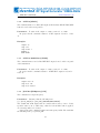
RF Signal Generator SG8-HP01M SG8-HPSS01M Operating Manual Rev. 1.5 Advantex LLC February 26, 2013 Russian Federation, 111250, Moscow, Krasnokazarmennaya st., 13/1 tel. +7 (495) 721-47-74, +7(495) 728-08-03 [email protected] http://advantexrf.com IF/RF & Microwave Design dvanteX 1 2 IF/RF & Microwave Design dvanteX SG8-HP(SS)01M-C2U42HP315 RF Signal Generator 10MHz-8GHz www.advantexrf.com CONTENTS Document Revisions Rev. 0.1 0.2 1.0 1.1 1.2 Date November 20, 2009 December 06, 2009 January 20, 2010 November 30, 2010 June 19, 2011 1.3 October 4, 2011 1.4 December 13, 2011 1.5 February 26, 2013 Description Preliminary version. Based on the firmware R0.1 Section 8 on page 42 added. (Firmware Update). Based on the firmware R0.2 Added remote control operations. (SCPI commands) Based on the firmware R1.0 Revised figures of block diagram, front and rear panel view Added the description of SG8-HPSS01M, revised Settings . Reference Freq and Info menu items, added new SCPI commands. Based on the firmware R1.1 Added sections “Package Contents”, “Installation, Maintenance and Safety”, “Disposal”, added new SCPI command STAT:QUES? STATus:QUEStionable:[EVENt]? command is replaced with STATus:QUEStionable:CONDition? Added *OPC? SCPI command (Firmware R1.3) For instruments based on the LNO-HP35M-RF synthesizer (SG8 versions starting from 2013) the issue with level glitch at turning on the RF Out has been resolved Contents 1 Package Contents 6 2 Overview 6 3 Installation, Maintenance and Safety 7 4 Control Elements and Interfaces 9 5 Graphical User Interface 11 5.1 Menu Navigation . . . . . . . . . . . . . . . . . . . . . . . . . . . 13 5.2 Status Bar . . . . . . . . . . . . . . . . . . . . . . . . . . . . . . . 13 5.3 Data Entry . . . . . . . . . . . . . . . . . . . . . . . . . . . . . . 15 6 Instrument Functions 6.1 Main Menu . . . . . . . . . . . . . . . . . . . . . 6.2 Operation Modes . . . . . . . . . . . . . . . . . . 6.2.1 Continuous Wave Operation Mode (CW) . 6.2.2 Sweep Frequency Operation Mode (SWF) 6.2.3 Sweep Level Operation Mode (SWL) . . . 3 . . . . . . . . . . . . . . . . . . . . . . . . . . . . . . . . . . . . . . . . . . . . . 18 18 19 19 21 24 IF/RF & Microwave Design dvanteX SG8-HP(SS)01M-C2U42HP315 RF Signal Generator 10MHz-8GHz www.advantexrf.com 6.3 6.4 6.5 6.6 LIST OF FIGURES 6.2.4 Frequency Modulation (FM) . . . . . . . . . . 6.2.5 Phase Modulation Operation Mode (PhM) . . Settings of the Instrument . . . . . . . . . . . . . . . 6.3.1 Reference Freq. . . . . . . . . . . . . . . . . . 6.3.2 Analog In input . . . . . . . . . . . . . . . . . Storing the Current Settings of the Instrument (Save Preset the Instrument (Load Default) . . . . . . . . . Information about the Instrument (Info) . . . . . . . . . . . . . . . . . . . . . . . . . . . . . . . . Current) . . . . . . . . . . 7 Remote Control 7.1 Quick Start . . . . . . . . . . . . . . . . . . . . . . . . . . . 7.2 SCPI Commands . . . . . . . . . . . . . . . . . . . . . . . . 7.2.1 SCPI Compliance . . . . . . . . . . . . . . . . . . . . 7.2.2 SCPI Summary . . . . . . . . . . . . . . . . . . . . . 7.3 SCPI Command List . . . . . . . . . . . . . . . . . . . . . . 7.3.1 *CLS . . . . . . . . . . . . . . . . . . . . . . . . . . 7.3.2 *IDN? . . . . . . . . . . . . . . . . . . . . . . . . . . 7.3.3 *RST . . . . . . . . . . . . . . . . . . . . . . . . . . 7.3.4 *OPC? . . . . . . . . . . . . . . . . . . . . . . . . . 7.3.5 SYSTem:ERRor[:NEXT]? . . . . . . . . . . . . . . . 7.3.6 OUTPut[:STATe] . . . . . . . . . . . . . . . . . . . . 7.3.7 OUTPut:ROSCillator[:STATe] . . . . . . . . . . . . 7.3.8 [SOURce:]FREQuency[:CW] . . . . . . . . . . . . . 7.3.9 [SOURce:]POWer[:LEVel][:IMMediate][:AMPLitude] 7.3.10 [SOURce:]PHASe[:ADJust] . . . . . . . . . . . . . . 7.3.11 [SOURce:]ROSCillator:SOURce . . . . . . . . . . . . 7.3.12 [SOURce:]ROSCillator:EXTernal:FREQuency . . . . 7.3.13 MEASure[:SCALar]:TEMPerature? . . . . . . . . . . 7.3.14 STATus:QUEStionable:CONDition? . . . . . . . . . . . . . . . . . . . . . . . . . . . . . . . . . . . . . . . . . . . . 26 29 30 30 31 32 33 33 . . . . . . . . . . . . . . . . . . . . . . . . . . . . . . . . . . . . . . 33 34 34 34 36 37 37 38 38 38 38 39 39 39 40 40 40 41 41 41 8 Firmware Update 42 9 Disposal 43 List of Figures 1 2 3 4 5 6 Block diagram of the RF-synthesizer block (HP option) . . . . . Block diagram of the RF-synthesizer with reference PLL (additional SS option) . . . . . . . . . . . . . . . . . . . . . . . . . . . Recommended connection of the device with sensitive input . . . Front panel view . . . . . . . . . . . . . . . . . . . . . . . . . . . Rear panel view . . . . . . . . . . . . . . . . . . . . . . . . . . . . Internal circuit connections for Aux In and Mic In inputs, resulting in Analog In and Triggering signals used in SWF/SWL and FM/PhM modes . . . . . . . . . . . . . . . . . . . . . . . . . . . 4 7 8 10 10 12 12 IF/RF & Microwave Design dvanteX SG8-HP(SS)01M-C2U42HP315 RF Signal Generator 10MHz-8GHz www.advantexrf.com LIST OF TABLES 7 8 9 10 11 12 13 14 15 16 17 18 19 20 21 22 23 24 25 26 27 28 29 30 31 Display . . . . . . . . . . . . . . . . . . . . . . . . . . . . . . . . 12 Keyboard . . . . . . . . . . . . . . . . . . . . . . . . . . . . . . . 16 Main menu . . . . . . . . . . . . . . . . . . . . . . . . . . . . . . 19 Operation Modes . . . . . . . . . . . . . . . . . . . . . . . . . . . 20 Continuous wave operation mode menu (Operation Modes . Continuous Wave) . . . . . . . . . . . . . . . . . . . . . . . . . . . . . . . . . 20 Sweep frequency/level parameters . . . . . . . . . . . . . . . . . . 21 Sweep frequency operation mode menu (Operation Modes . Sweep Frequency) . . . . . . . . . . . . . . . . . . . . . . . . . . . . . . . 22 Sweep frequency mode options (Operation Modes . Sweep FrequencyOPT) . . . . . . . . . . . . . . . . . . . . . . . . . . . . . . . . . 23 Spectrum envelop in sweep frequency mode . . . . . . . . . . . . 24 Sweep level operation mode menu (Operation Modes . Sweep Level) 25 Sweep level mode options (Operation Modes . Sweep Level-OPT) . 26 Frequency modulation mode (Operation Modes . Freq. Modulation) 27 Frequency modulation options (Operation Modes . Freq. ModulationOPT) . . . . . . . . . . . . . . . . . . . . . . . . . . . . . . . . . 28 Phase modulation mode (Operation Modes . Phi Modulation) . . . 29 Phase modulation options (Operation Modes . Phi Modulation-OPT) 30 Instrument general settings (Settings) . . . . . . . . . . . . . . . 31 Reference frequency settings (Settings . Reference Freq.) . . . . . 32 Analog In settings (Settings . Analog In) . . . . . . . . . . . . . . 32 Information about the instrument (Info) . . . . . . . . . . . . . . 34 Example of the remote control using HyperTerminal application 35 COM-port settings . . . . . . . . . . . . . . . . . . . . . . . . . . 35 Instrument control and command processing model . . . . . . . . 36 Command structure . . . . . . . . . . . . . . . . . . . . . . . . . 37 Device Manager window (My Computer . Manage) . . . . . . . . . 42 Firmware update application – XMI Programmer . . . . . . . . . 44 List of Tables 1 2 3 4 Status bar Info . . . . . . . . . . . . . . . Math operations and numerical data entry Sweep frequency shapes . . . . . . . . . . Sweep level shapes . . . . . . . . . . . . . 5 . . . . . . . . . . . . . . . . . . . . . . . . . . . . . . . . . . . . . . . . . . . . . . . . . . . . 15 16 23 26 IF/RF & Microwave Design dvanteX SG8-HP(SS)01M-C2U42HP315 RF Signal Generator 10MHz-8GHz www.advantexrf.com 1 2 OVERVIEW Package Contents The following items are included to the delivery package: Item# Description 1 SG8 RF Signal Generator 10 MHz – 8 GHz 2 AC power cord with CEE 7/7 (E+F Type) plug 3 USB Cable A-B, 3m (9.8ft.) 4 RS-232 Cable, D-sub 9F - D-sub 9M, 3m (9.8ft.) 5 CD with drivers and documentation 6 SG8 Operating Manual (printed version) 7 Calibration certificate 8 Warranty certificate 9 Packing List Qty. 1 1 1 0/1 1 1 1 1 1 Note Note 1 Note 2 Note 1: By default the power cord with CEE 7/7 (E+F Type) plug is placed if not explicitly specified by the customer. Note 2: By default it’s not placed if not requested by customer. 2 Overview Figure 1 shows the block diagram of the RF-synthesizer, the main block of the instrument. Reference frequency signal is fed to the positive input of phasefrequency detector (PFD) . PFD output signal is fed to the loop-filter, then to the octave VCO control input. Via splitter signal is fed to fixed frequency divider by 8, then to Direct Digital Synthesizer (DDS). Signal from the output of the DDS is being filtered and fed to the negative PFD input, thus closing the feed-back loop of the PLL system. DDS is used in this scheme like frequency divider with very small step of the division factor tuning. VCO output signal is fed further to frequency division block, following by the harmonic filtering block. From the filtering block it’s further fed to the automatic power control block (APC), then to the RF Out output. Output amplifier is connected with output connector directly (via APC’s splitter), so it allows to gain maximum power at the RF Out which output stage is capable of. There are some rations of output and reference frequencies at which extra spurs produced by the DDS appear at the output. In order to avoid this effect the switchable reference frequency source can be applied. Figure 2 shows the block diagram of the instrument with additional spur suppression option (SS option). The difference consists of the second reference frequency generation for the RF-synthesizer block. The original reference frequency (147 MHz) from internal TCXO is fed to the PLL with VCXO and very narrow loop filter. PLL forms the second reference frequency 150 MHz. Signals from internal reference source and PLL are connected to the switch and its output is connected with reference frequency input of the RF-synthesizer. Either 147 or 150 MHz is used in accordance with given frequency at the RF Out output. The selection of the reference frequency is automatically controlled by the instrument to obtain least possible spur level. The accuracy of the output frequency step while 6 IF/RF & Microwave Design dvanteX 3 SG8-HP(SS)01M-C2U42HP315 RF Signal Generator 10MHz-8GHz INSTALLATION, MAINTENANCE AND SAFETY www.advantexrf.com 147MHz + PFD VCO CP 1/2N 4-8GHz - REF In N DDS REF Out 1/8 F, φ RF On/Off RF Out 4MHz-8GHz Coupler P Figure 1: Block diagram of the RF-synthesizer block (HP option) reference switching is maintained due to the fixed phase relation between 147 and 150 MHz, and narrow band phase response of the reference PLL allows to preserve the relatively low phase noise level as it would be without additional reference PLL system. 3 Installation, Maintenance and Safety When installing the instrument, please note the following: • SG8 Signal Generator is designed for laboratory use only and is not protected against moisture and mud. • Some space from the bottom and rear side should be provided to ensure proper air cooling of the instrument. • During connecting cables or other equipment make certain that connectors correspond to each other, and are in proper condition. Otherwise some damage to instrument’s connectors may occur. • A grounded, three pin AC power receptacle should be used for power supply of the instrument. The grounded pin of the AC power cord is internally connected to the instrument’s chassis. • When connecting equipment to the instrument, make sure that all equipment are properly grounded and there is no voltage difference between their cases. Otherwise it may result in damage of the instrument’s input or output. 7 ! IF/RF & Microwave Design dvanteX SG8-HP(SS)01M-C2U42HP315 RF Signal Generator 10MHz-8GHz www.advantexrf.com 3 INSTALLATION, MAINTENANCE AND SAFETY REF In REF Out 147MHz + PFD CP PFD CP VCXO 150MHz - + VCO 4-8GHz - 1/2N N DDS 1/8 F, φ RF On/Off RF Out 4MHz-8GHz Coupler P Figure 2: Block diagram of the RF-synthesizer with reference PLL (additional SS option) 8 IF/RF & Microwave Design dvanteX 4 SG8-HP(SS)01M-C2U42HP315 RF Signal Generator 10MHz-8GHz CONTROL ELEMENTS AND INTERFACES www.advantexrf.com When installing and turning on the instrument, it is recommended to follow the order listed below: ! 1. Verify that front panel power ON/OFF button (item 4, fig. 4) is turned off (not in depressed position). 2. Verify that rear panel AC power ON/OFF switch (item 1, fig. 5) is turned off. 3. Connect AC power cord to the instrument and to AC wall power supply. 4. Turn on the AC power switch at the rear panel of the instrument. 5. Turn on the ON/OFF button at the front panel of the instrument. Text corresponding to the current operation mode should be displayed on the screen. 6. To turn off the instrument just press the ON/OFF button at the front panel. With long-term non-use of the device it is recommended to turn off the AC power switch at the rear panel. Before doing this make certain that the instrument is off. Over time, the deviation of the output signal level and frequency from the specified values may increase, so the device should be calibrated periodically. Recommended calibration interval is 1 year. 4 i Control Elements and Interfaces Figure 4 shows the front panel view of the instrument. The elements are designated with the following callouts: 1. RF-signal output (RF Out), N-type connector; 2. RF Out ON/OFF LED indicator, light means RF Out is On; 3. RF Out ON/OFF button. Actually it turns on and off the power supply of the output stage amplifier, the other part of the instrument continues to work, i.e. even when RF-output is OFF all instrument functions are available and make an effect on the instrument state. By default RF Out is always OFF when the device is turned on or reset via remote control; ! In early versions of SG8 (before year 2013) turning on the RF Out resulted in short glitch of the RF level 4. Power On/Off button. It turns off all circuits except first AC/DC convertor; about 5 ms width. Therefore for in- 5. Graphical OLED display with 128 x 64 resolution, yellow color, 4-bit; with sensitive input, it’s strongly rec- 6. Rotary knob, 24 positions per 360°; 7. Keyboard; 9 struments assembled before 2013 when connecting to the RF Out a device ommended to use external fixed attenuator (see figure 3) IF/RF & Microwave Design dvanteX SG8-HP(SS)01M-C2U42HP315 RF Signal Generator 10MHz-8GHz www.advantexrf.com 4 CONTROL ELEMENTS AND INTERFACES SG8 RF Signal Generator RF OUT 8.000 GHz +20dBm RF IN Attenuator Figure 3: Recommended connection of the device with sensitive input 5 7 6 4 3 2 1 8 Figure 4: Front panel view 10 IF/RF & Microwave Design dvanteX 5 SG8-HP(SS)01M-C2U42HP315 RF Signal Generator 10MHz-8GHz GRAPHICAL USER INTERFACE www.advantexrf.com 8. Context sensitive menu keys. Figure 5 shows rear panel view of the instrument. Its elements are designated with the following callouts: 1. Main AC power supply switch, it turns off all circuits including first AC/DC convertor; 2. USB interface for the connection to PC; 3. RS-232 interface for the PC’s COM-port connection. 9-pin D-Sub connector; 4. Fan for cooling; 5. Grounding terminal. Actually grounding is provided via central pin of the standard power supply cord, so this auxiliary terminal should be used only if your AC socket has no any grounding pins; 6. Reference frequency output (REF Out). Signal can be translated from REF In input (HP version only) or fed from internal reference source (HP and HPSS versions). SMA-type connector, female; 7. External reference frequency input (REF In). SMA-type connector, female; 8. Auxiliary input (Aux In), can be used as external trigger input when instrument is in sweep frequency or level mode, and as analog input of modulation signal used in FM/PhM modes. BNC-type connector; i Figure 6 shows the internal circuit connections for the Aux In 9. Microphone input (Mic In); and Mic In inputs 10. AC power supply connector with fuse. Signals from Aux In and Mic In inputs are fed to the variable gain amplifier (VGA) and comparator, forming accordingly Analog In, used as modulating signal, and Triggering – for synchronous run in Sweep Frequency and Sweep Level modes, see figure 6. 5 Graphical User Interface Figure 7 shows the display screen view. It is divided into several fields: Status Bar (1), Menu Items which can be textual, numeric and graphical (2), Context Sensitive Menu (3) which depends on the currently selected item, and Scroll bar (4) showing the current position of the displayed window relative to the whole menu item list. Menu consists of the items arranged in left-to-right and top-tobottom order. (2.1-2.4). The number of the items can vary from a few to dozens making up several lines of the screen. One line can contain more than one item. In the case of more than three lines scroll bar appears on the screen. Some items can be shaded (have less brightness, 2.3). It means that in this operation mode 11 i It’s recommended to use 2A / 250V fuse IF/RF & Microwave Design dvanteX SG8-HP(SS)01M-C2U42HP315 RF Signal Generator 10MHz-8GHz www.advantexrf.com 1 5 2 3 GRAPHICAL USER INTERFACE 4 5 7 10 9 8 6 Figure 5: Rear panel view +3V GND 510 510 3k Mic In 10k 1uF Aux In 10k VGA G=1..64 + - 100 Analog In Triggering + Comparator Figure 6: Internal circuit connections for Aux In and Mic In inputs, resulting in Analog In and Triggering signals used in SWF/SWL and FM/PhM modes 2.1 1 4 2 2.2 2.3 3 3.1 3.2 3.3 3.4 Figure 7: Display 12 2.4 IF/RF & Microwave Design dvanteX 5 SG8-HP(SS)01M-C2U42HP315 RF Signal Generator 10MHz-8GHz GRAPHICAL USER INTERFACE www.advantexrf.com these items are blocked (not used) or used only to display information (i.e. not editable by the user) or can’t be used to launch the operation corresponding this item. When navigating through menu items the current item is being selected (2.2). When entering data numerical item turns active (i.e. becomes more brighter, see 2.4), it means that the item is in the numerical data editing mode. Menu can have hierarchical structure, the moving between levels can be performed with aid of context sensitive menu (3). 5.1 Menu Navigation Navigation through the menu items (moving to next or previous item, entering to sub-menu or one level up) can be performed by the context menu buttons (see figure 4, item 8), and rotary knob (item 6). RET – moving one level up; ↑ – moving to previous item; ↓ – moving to the next item; >> – entering to the sub-menu (one level down); OPT – entering to the options menu of the current operation mode. Rotating knob clockwise corresponds to ↓ command, counterclockwise – ↑, pressing knob – >>. 5.2 Status Bar Status bar (top line of the screen) displays the current operation mode and settings of the instrument. An information displayed in the status bar in symbol form is listed below. Current operation mode: – Continuous Wave; – Sweep Frequency; – Sweep Frequency Center, the same as above but as opposed to SWF in place of Start and Stop Frequency it requires to specify Center Frequency and Span accordingly; – Sweep Level1 ; – Frequency Modulation; – Phase Modulation. The shape of the modulating signal or the type of the frequency or level sweep. 1 Term “Signal Level” means the power of the RF-signal in this document unless otherwise noted 13 IF/RF & Microwave Design dvanteX SG8-HP(SS)01M-C2U42HP315 RF Signal Generator 10MHz-8GHz www.advantexrf.com 5 GRAPHICAL USER INTERFACE – Saw, defines the shape of the sweep (frequency or level); – Triangle, defines the shape of the sweep (frequency or level); – Sine, defines modulating signal of the internal source in FM/PhM modes; – Square, defines modulating signal of the internal source in FM/PhM modes. Triggering type used in SWF (Sweep Frequency) and SWL (Sweep Level) modes: – Auto. The instrument doesn’t wait for external triggering event to repeat new run. New run starts immediately after the previous one is over; – Single run. After one run (period) is over, the instrument waits for the triggering event to start new run; – Step. The instrument waits for the triggering event after each sweep step. The source of the modulating signal and the source of external triggering event: – (Manual) manual triggering by means of pressing TRIG softkey in SWF or SWL mode; – (Positive Slope) triggering event occurs at the rising edge of the signal fed to Aux In input in SWF or SWL mode; – (Negative Slope) triggering event occurs at the falling edge of the signal fed to Aux In input in SWF or SWL mode; – (External) Analog In signal, formed by the Aux In or Mic In inputs (see figure 6), is used as a modulating signal in FM or PhM modes; – (Internal) internal source is used as the modulating signal in modes FM or PhM. Reference frequency settings (by default the internal reference source is used, REF Out is Off): – REF Out is On. Internal reference frequency source is used, and this signal is applied to REF Out output; – REF Out is Off and external reference frequency source is used; 14 IF/RF & Microwave Design dvanteX 5 SG8-HP(SS)01M-C2U42HP315 RF Signal Generator 10MHz-8GHz GRAPHICAL USER INTERFACE Operation Mode Table 1: Status bar Info Waveform/ Triggering Source Shape www.advantexrf.com Reference Warnings UNC OVT #XX – REF Out is On and external reference frequency source is used. Warnings and Errors: UNC – (Uncalibrated) means that value of one of the parameters of the current mode of operation is out of calibrated range; OVT – (Overtime) microcontroller does not have time to process the event queue; #XX – (Error Code) last error code. Table 1 shows status bar symbols in the order they appear on the screen. 5.3 Data Entry Numerical data entry can be performed either using the keyboard (fig. 4, item 7) or the rotary knob (item 6). The default state of the rotary knob is the menu navigation mode. Single click the knob on the selected numerical menu item (e.g. see fig. 7, item. 2.2) puts the menu item to the numerical data entry mode, rotation of the knob corresponds to the increase or decrease of the numerical value. To exit from the numerical entry mode to the navigation mode just click the knob again or press one of the context sensitive menu keys (RET, ↓, ↑). The instrument keyboard is divided into several groups (fig. 8): 1. Numeric buttons (D group); 2. Backspace (B) – deletes the last input symbol; 3. Enter/Units (E group); 15 IF/RF & Microwave Design dvanteX SG8-HP(SS)01M-C2U42HP315 RF Signal Generator 10MHz-8GHz www.advantexrf.com 5 GRAPHICAL USER INTERFACE 2 [B] 3 [E] 1 [D] 4 [C] Figure 8: Keyboard 4. Operations (C group). Numerical entry mode is automatically activated by pressing any of the D, B or C group keys. The pressing on any key of E group performs the entry of the input data following by the exit from the numerical entry mode. When pressing E group key in navigation mode, the change of the unit scale factor is performed, e.g. if the current frequency value is 1’000’000’000.00 Hz, then after pressing [MHz] key the value 1’000.000 000 00 MHz will appear on the screen, and so on. When changing unit scale factor (i.e. k – kilo, M – mega, e.t.c.) the increment step of the edited value while rotating the knob will also change. Typically the minimum step while rotating the knob equals to the one-tenth of the selected unit scale, i.e. if the current unit scale is kHz, then rotary knob step will be 0.1 kHz. With increasing rotation speed step increases. Table 2 shows examples of some operations and corresponding command sequences. Table 2: Math operations and numerical data entry Sequence Expression E R Description Used for unit scale factor entry, e.g. Hz, kHz, MHz, GHz, also it’s used to repeat the last entered command. To do so (to repeat the operation with the last operand) the same button of E-group which was used last time should be pressed. Otherwise the exit from command repeat mode is performed.2 (continued on next page) 2 Exit from last operation repeat mode can also be performed by pressing “Bck” (after last pressed E-group button) 16 IF/RF & Microwave Design dvanteX 5 SG8-HP(SS)01M-C2U42HP315 RF Signal Generator 10MHz-8GHz GRAPHICAL USER INTERFACE www.advantexrf.com (continued Table 2, beginning on page 16) Sequence Expression Description As a valid “C”-key it’s possible only “−”. CE R · (−1) Used for negative value entry. Direct input of numeric value. Unit scale factor is defined by pressed “E” button, i.e. DE D by pressed unit (µs, ms, dBm, kHz and so on) As a valid “C”-key it’s possible only “−”. Used for negative value entry. For DCE D · (−1) example, to enter −10 dBm you should press the following: “1”, “0”, “−”, “dBm” It is used in conjunction with “E”-key for quick data entry with linear or exponential increment step. For example, to set consequently frequencies 100, 110, 120, 130, 140 MHz just set 100 MHz at first, then press “+”, “1”, “0”, “MHz”, and after each next pressing of “MHz” key the value CDE R~D will be increased by 10 MHz. This sequence can also be useful to offset from current value. For example, you need to set 0.999 998 GHz. It will take less time if you set 1 GHz first by D E sequence, and then subtract from it 2 kHz by pressing C D E sequence. Can be used for evaluation of mathematical expression along with result DCDE D1 ~ D2 data entry. For example, when entering multiple frequencies.3 CDCE (R ~ D) · (−1) Rarely used (continued on next page) 3 When evaluating expressions with several operands – all of them except the last one have current unit scale factor (µ, m, k, M, G), i.e. the factor that was valid before the entry process. The last operand has unit scale factor corresponding to pressed “E”-key closing the sequence. For the operands without units like in expressions “*” and “/” scale factor equals 1. For example the sequence “*”, “2”, “kHz” multiplies current value by 2 and displays the result in “kHz” units. Factor values in “*” and “/” operations have 10-3 accuracy and maximum value not less than 10+3 . 17 IF/RF & Microwave Design dvanteX SG8-HP(SS)01M-C2U42HP315 RF Signal Generator 10MHz-8GHz www.advantexrf.com 6 INSTRUMENT FUNCTIONS (continued Table 2, beginning on page 16) Sequence Expression Description Can be used for evaluation of mathematical expression along with result data entry. When used sequences with arbitrary number of operands, the intermediate result isn’t loaded to the instrument immediately, only the final CDCDE (R ~A D1 ) ~B D2 result after pressing “E”-key is loaded. Thus the intermediate results are restricted only to the capacity of operands while evaluation the expression. 4 Each next “E”-key pressing repeats the last operation with the last operand of the input sequence. Can be used to evaluate expressions such D C D C D E (D1 ~A D2 ) ~B D3 as D · m/n R – current value, ~ – operation (+, −, ÷, ∗), D – entered numerical value. 6 6.1 Instrument Functions Main Menu Main menu of the instrument consists of the following items (fig. 9): Operation Modes – contains sub-menu corresponding to modes of operation (CW, SWF, SWL, FM, PhM); Settings – contains sub-menu with the basic settings of the instrument relating to all modes of operations or to a group of modes; Save Current – the command saves the current settings and values of all numerical parameters. When powering up the instrument it will be initialized by the values stored by Save Current command; Load Default – the command loads default values for all parameters; Info – contains information about the instrument. When powering up the instrument tries to read from the nonvolatile memory (EEPROM) setting values stored previously by Save Current command. If checksum is valid, i.e. data is valid, then stored values are loaded, if not – the default values which are defined by the vendor are loaded to the instrument. 4 Integer 64-bit. Internal fixed point evaluation algorithm applies 104 factor for Hz, 102 – for dBm and degrees, 109 – for seconds. 18 IF/RF & Microwave Design dvanteX 6 SG8-HP(SS)01M-C2U42HP315 RF Signal Generator 10MHz-8GHz www.advantexrf.com INSTRUMENT FUNCTIONS Modes of operation General settings of the instrument Stores current settings of the instrument to the nonvolatile memory Sub-menu entry Presets the instrument Information about the instrument Figure 9: Main menu 6.2 Operation Modes The instrument has five operation modes listed in Operation Modes menu (fig. 10): Continuous Wave – CW ; Sweep Frequency – SWF; Sweep Level – SWL; Freq. Modulation – FM; Phi Modulation – PhM, phase modulation. When powering up the instrument is in one of the modes listed above regardless of the current position within the menu system. The current mode of operation is displayed in the status bar at the top left corner of the screen. (see section 5.2 on page 13). The switching between modes is performed by entering the corresponding menu item. Each operation mode has its own independent set of parameters. Any changes made to operation mode settings are saved while exiting and switching to another mode until the power is turned off. When powering up the mode is loaded which was current before the Save Current command was clicked. Continuous Wave (CW) is the default mode of operation. 6.2.1 Continuous Wave Operation Mode (CW) Continuous Wave operation mode (CW) has following parameters (fig. 11 on the next page): Frequency – RF output signal frequency; 19 IF/RF & Microwave Design dvanteX SG8-HP(SS)01M-C2U42HP315 RF Signal Generator 10MHz-8GHz www.advantexrf.com 6 INSTRUMENT FUNCTIONS Continuous wave mode Sweep frequency mode Sweep output level mode Frequency modulation Phase modulation Figure 10: Operation Modes Output frequency Output level Phase offset Return – exit from sub-menu Figure 11: Continuous wave operation mode menu (Operation Modes . Continuous Wave) Level – RF signal level; Phase – RF signal phase offset. The frequency can be set in increments of 0.0001 Hz in spite of the fact that only 12 leading digits are displayed on the screen. Such values can be set directly by “D E” sequence, and the digits which are do not fit the screen are nevertheless took into account, or another way – you can use “C D E” sequence, when you can set rounded value first and then using “+” or “−” operations you can add the appropriate offset. In most cases it’s not necessary to set values with such precision, since the stability of the reference source is usually much lower. However if one reference frequency source common for both instruments is used, and you need to provide slow phase drift of one RF signal relative to another, it can be done as described above. Resulting RF signal phase is described by the following equation ϕout = ωc t + ϕo (ωc ) + ϕ, where ωc – RF signal central frequency, t – time, ϕo (ωc ) – initial phase offset (generally depends on the central frequency and start time), ϕ – phase offset 20 IF/RF & Microwave Design dvanteX 6 SG8-HP(SS)01M-C2U42HP315 RF Signal Generator 10MHz-8GHz www.advantexrf.com INSTRUMENT FUNCTIONS Stop Freq. / Level Dwell Time TSweep Step Start Freq. / Level Figure 12: Sweep frequency/level parameters defined by Phase parameter of the CW mode. Thus, in order to produce two RF signals with a given phase offset you need to use single frequency reference source for both instruments, set the same frequency, and adjust ϕ one of the instruments to compensate for the initial phase offset ϕo . A further change in phase gives relative ϕ phase offset with a quite high accuracy. 6.2.2 Sweep Frequency Operation Mode (SWF) Sweep frequency is a step change of output frequency by the specified shape (e.g. triangle, saw) at a constant signal level. (fig. 12). TSweep – time of one period. SWF mode has the following parameters (fig. 13): Start Frequency – start frequency; Stop Frequency – stop frequency; Level – RF signal level; Dwell Time – one step time; Frequency Step – frequency step size. Sweep frequency mode has the following options (fig. 14): • Sweep mode type: – Auto – automatic, after one period pass it repeats automatically; – Single – single period pass. Sweep starts at triggering event. Then after one pass it returns to the start and waits for the next triggering event; – Step – stepping mode. Each step is performed after triggering event; • Triggering options: – Manual – triggering event performed manually by pressing TRIG softkey (see fig. 13); 21 IF/RF & Microwave Design dvanteX SG8-HP(SS)01M-C2U42HP315 RF Signal Generator 10MHz-8GHz www.advantexrf.com 6 INSTRUMENT FUNCTIONS Start frequency Stop frequency Manual triggering Output level Sweep frequency mode options (entry to sub-benu) Current frequency value Dwell Time Frequency Step Figure 13: Sweep frequency operation mode menu (Operation Modes . Sweep Frequency) i When Ext option is activated triggering event can also be generated manually by TRIG softkey – External – triggering event is generated by external signal fed to Aux In input; ∗ Trig Slope: · Positive – triggering event is generated at the rising edge of the external signal; · Negative – triggering event is generated at the falling edge of the external signal; • Dwell Time – this sub-menu item duplicates the corresponding menu item in fig. 13; • Frequency Step – this sub-menu item duplicates the corresponding menu item in fig. 13; • Sweeping law (i.e. Shape): – Saw – saw shape; – Tri – triangle; • Frequency display settings: – F1 − F2 – when this option is activated first and second frequency fields shown in fig. 13 correspond to the start and stop frequency, accordingly; – FC ± ∆ – when this option is activated first and second frequency fields shown in fig. 13 correspond to the central frequency and span, accordingly. 22 IF/RF & Microwave Design dvanteX 6 SG8-HP(SS)01M-C2U42HP315 RF Signal Generator 10MHz-8GHz www.advantexrf.com INSTRUMENT FUNCTIONS Frequency Step (sub-menu entry) Automatic run repeat Sweep shape: saw / triangle Single run Single step Manual triggering/ Triggering on external signal Frequency input mode: Start–Stop/Center–Span Triggering on rising/ falling edge of ext. signal One step time (Dwell Time) (sub-menu entry) Figure 14: Sweep frequency mode options (Operation Modes . Sweep FrequencyOPT) SWF (SWFC ) Table 3: Sweep frequency shapes FStart < FStop FStart > FStop (Span>0) (Span<0) Saw Triangle 23 IF/RF & Microwave Design dvanteX SG8-HP(SS)01M-C2U42HP315 RF Signal Generator 10MHz-8GHz www.advantexrf.com 6 Level INSTRUMENT FUNCTIONS Level FB FB Freq. & Time Freq. & Time Figure 15: Spectrum envelop in sweep frequency mode Table 3 shows shapes of frequency sweep at various relations of start and stop frequency values. Output RF signal frequency is produced by dividing the octave VCO band by factor multiple of two. The switching boundaries are as follows: 4 000, 2 000, 1 000, 500, 250, 125, 62.5, 31.25, 15.625, 7.8125, 3.90625 MHz. In the sweep frequency mode the calibrated output level is calculated and set for each frequency step. Therefore, even for wide range of frequency sweeping the output level remains constant (within the error). If the sweeping range includes one of the switching boundaries of the frequency divider, then while switching to another divider an unavoidable frequency glitch occurs, since the VCO can’t be tuned instantly. In order to avoid the frequency components in spectrum outside the given sweeping range (it may have significance in some applications) the output signal is turned off for some time while the VCO is tuned. In early versions of SG8 (before 2013) when turning on the signal, a glitch of output level may occur as a result of APC operation. Figure 15 shows spectrum envelop in sweep frequency mode at small dwell time values and when the switching boundary FB resides within and outside sweeping range. To avoid this issue you can use frequency modulation (FM) mode instead of SWF. In this way the switching of the dividers doesn’t occur, since the VCO margin is used. However the same margin limits the maximum sweep span to a much less value compared to SWF mode. 6.2.3 Sweep Level Operation Mode (SWL) SWL mode is the step change of output level by the specified law (e.g. triangle, saw) at constant frequency (fig. 12). TSweep – one pass (period) time. Sweep level mode (SWL) has the following parameters (fig. 16): Frequency – output frequency; Start Level – output start level; Stop Level – output final level; Dwell Time – time of one step; Level Step – level step size. 24 IF/RF & Microwave Design dvanteX 6 SG8-HP(SS)01M-C2U42HP315 RF Signal Generator 10MHz-8GHz www.advantexrf.com INSTRUMENT FUNCTIONS Output frequency Start Level Stop Level Current Level Manual Triggering softkey One step time (Dwell Time) Level Step Figure 16: Sweep level operation mode menu (Operation Modes . Sweep Level) Sweep level operation mode has the following options (fig. 17): • Sweep mode type: – Auto – automatic, after one period pass it repeats automatically; – Single – single period pass. Sweep starts at triggering event. Then after one pass it returns to the start and waits for the next triggering event; – Step – stepping mode. Each step is performed after triggering event; • Triggering options: – Manual – triggering event performed manually by pressing TRIG softkey (see fig. 16); – External – triggering event is generated by external signal fed to Aux In input; ∗ Trig Slope: · Positive – triggering event is generated at the rising edge of the external signal; · Negative – triggering event is generated at the falling edge of the external signal; • Dwell Time – this sub-menu item duplicates the corresponding menu item in fig. 16; • Level Step – this sub-menu item duplicates the corresponding menu item in fig. 16; 25 i When Ext option is activated triggering event can also be generated manually by TRIG softkey IF/RF & Microwave Design dvanteX SG8-HP(SS)01M-C2U42HP315 RF Signal Generator 10MHz-8GHz www.advantexrf.com 6 INSTRUMENT FUNCTIONS Triggering on rising/falling edge Auto run Single run One step time (sub-menu entry) Single step Level step (sub-menu entry) Manual triggering/ Triggering on ext. signal Sweep shape: saw / triangle Figure 17: Sweep level mode options (Operation Modes . Sweep Level-OPT) Table 4: Sweep level shapes PStart < PStop PStart > PStop SWL Saw Triangle • Sweeping law (i.e. Shape): – Saw – saw shape; – Tri – triangle; Table 4 shows shapes of level sweep at various relations of start and stop level values. 6.2.4 Frequency Modulation (FM) Frequency modulation is the deviation of instantaneous frequency from its central (i.e. mean) value in accordance to the modulating signal. It can be represented by the following expression: ω(t) = ωC + ∆ · s(t), where ω(t) – instantaneous frequency, ωC – central frequency (mean value), s(t) – modulating signal, ∆ – Frequency Sensitivity, Hz/V. The value of max |∆ · s(t)| is referred to as the Frequency Deviation. Since the frequency is the first derivative of the phase, the phase of the output signal will be ˆ t ϕ(t) = ωC t + ∆ s(τ )dτ. −∞ 26 IF/RF & Microwave Design dvanteX 6 SG8-HP(SS)01M-C2U42HP315 RF Signal Generator 10MHz-8GHz www.advantexrf.com INSTRUMENT FUNCTIONS Center frequency Graphic bar for modulating signal level indication Output level Minimum Mean Maximum Frequency Deviation Freq. Sensitivity Frequency of modulating signal (internal source ) Figure 18: Frequency modulation mode (Operation Modes . Freq. Modulation) If sinusoidal signal with intrinsic frequency Ω and deviation ∆ is used as the modulating signal in FM mode, then phase of output RF signal can be represented in the following form ϕ(t) = ωC t + ∆ sin(Ωt). Ω Frequency modulation mode has the following parameters (fig. 18): Center Frequency – central (mean) frequency; Level – output signal level; Frequency Deviation – used only for internal source of modulating signal (item is grayed in other modes); Frequency Sensitivity – used only in mode of external modulating signal fed to Aux In or Mic In input (it’s grayed in other modes); Source Frequency – frequency of modulating signal (only for internal source, this item is grayed otherwise). In FM mode such parameters of modulating signal as its minimum, maximum and mean values are displayed in form of graphical bar (fig. 18). Frequency modulation mode has the following options (fig. 19): • Source of modulating signal: – Internal – internal source; – External – external signal fed to Aux In or Mic In input; • Waveform of modulating signal: – Sine – sinusoidal signal; 27 IF/RF & Microwave Design dvanteX SG8-HP(SS)01M-C2U42HP315 RF Signal Generator 10MHz-8GHz www.advantexrf.com 6 INSTRUMENT FUNCTIONS Internal / external source of modulating signal Modulating signal waveform: sine / square Frequency Deviation (sub-menu entry) Frequency modulation sensitivity (sub-menu entry) Frequency of internal modulating source Figure 19: Frequency modulation options (Operation Modes . Freq. ModulationOPT) – Square – square signal; • FM Deviation, FM Sensitivity, Int Source Freq – these sub-menu items duplicate the corresponding items shown in fig. 18. ! Frequency modulation is implemented in digital way Modulation modes in the instrument are implemented in digital form. That is the modulating signal is the result of analog to digital conversion of Analog In signal or digital waveform implementation. Sampled values are converted to frequency (for FM) or phase (for PhM) and then loaded into the RF synthesizer block. Unlike the SWF mode, where the RF output level calculation is performed for each frequency using special calibrating data corresponding to particular frequency, in FM mode in order to accelerate the computation only center frequency calibration data is used. Since the deviation is much less than central frequency, it doesn’t lead to considerable error. For an effective use of ADC resolution the input variable gain amplifier (VGA) is provided, fig. 6. Graphical bar, fig. 13, shows minimums and maximums of sampled signal relative to the full scale of ADC. 28 IF/RF & Microwave Design dvanteX 6 SG8-HP(SS)01M-C2U42HP315 RF Signal Generator 10MHz-8GHz www.advantexrf.com INSTRUMENT FUNCTIONS Center frequency Graphic bar for modulating signal indication Output level Minimum Mean Maximum Phase Deviation Phase Sensitivity Frequency of modulating signal Figure 20: Phase modulation mode (Operation Modes . Phi Modulation) 6.2.5 Phase Modulation Operation Mode (PhM) Phase modulation of RF signal is the current phase deviation from the value corresponding to the integral of its center frequency ϕ(t) = ωC t + ∆ · s(t), where ωC – center frequency, s(t) – modulating signal, ∆ – Phase Sensitivity, rad/V. Value max |∆ · s(t)| is referred to as Phase Deviation. Phase modulation mode has the following parameters (fig. 20): Center Frequency – center frequency of RF signal; Level – output level of RF signal; Phase Deviation – used only in internal source mode, grayed otherwise; Phase Sensitivity – used only in external source mode, when modulating signal is fed to Aux In or Mic In input; Source Frequency – intrinsic frequency of modulating signal (only for internal source). In PhM mode the min, max and mean values of modulating signal are displayed on the screen in form of graphic bar (fig. 20). PhM mode has the following options (fig. 21): • Source of modulating signal: ! Phase modulation is implemented digitally – Internal – internal source; – External – external modulating signal fed to Aux In or Mic In input; • Waveform of modulating signal: – Sine – sinusoidal signal; 29 IF/RF & Microwave Design dvanteX SG8-HP(SS)01M-C2U42HP315 RF Signal Generator 10MHz-8GHz www.advantexrf.com 6 INSTRUMENT FUNCTIONS Internal / External source of modulating signal Modulating signal waveform: sine / square Phase Deviation (sub-menu entry) Phase modulation sensitivity (sub-menu entry) Frequency of internal source of modulating signal Figure 21: Phase modulation options (Operation Modes . Phi Modulation-OPT) – Square – square signal; • PhM Deviation, PhM Sensitivity, Int Source Freq – these sub-menu items duplicate the corresponding items shown in fig. 20. 6.3 Settings of the Instrument Settings menu contains the following items (fig. 22): Reference Frequency – sub-menu with settings of reference frequency; Analog In – sub-menu with settings of analog signal inputs – Aux In and Mic In. 6.3.1 Reference Freq. Reference Freq. menu contains the following items (fig. 23): • External reference frequency value (Ext Ref Freq) – used to set frequency of external reference source. For the correct operation of the instrument it should correspond to the actual frequency of the signal fed to Ref In input.; 30 IF/RF & Microwave Design dvanteX 6 SG8-HP(SS)01M-C2U42HP315 RF Signal Generator 10MHz-8GHz www.advantexrf.com INSTRUMENT FUNCTIONS Reference frequency settings Analog In input settings Figure 22: Instrument general settings (Settings) • Internal reference frequency value (Int Ref Freq), not editable. • Reference frequency source (Source): – Internal – internal source is used; – External – signal fed to the REF In input is used as the reference; • Reference frequency output (Ref Output): – On – output is on, and the reference frequency signal is available at REF Out output. When internal source is used the signal is taken from it, when external is used – signal is taken from REF In input and duplicated to the REF Out output (only in SG8-HP); – Off – REF Out output is off. • Dual reference frequency mode (Int Ref Mode).5 – Auto – automatic switching of used reference frequency. In this mode the instrument automatically chooses the right frequency to minimize the spurs at the RF output. An Auto mode works only in CW mode of operation, in other cases the fixed 174 MHz reference is used; – Fixed 147 – fixed 147 MHz reference; – Fixed 150 – fixed 150 MHz reference. 6.3.2 Analog In input Analog In settings menu (fig. 24) contains the gain of the Analog In signal, which is the difference between the signal fed to Aux In and Mic In inputs (see. 6). The gain can take one of the following values: 1, 2, 4, 8, 16, 32, 64. Looking at the signal level displayed by the graphical bar on the screen in FM or PhM mode, 5 These menu items are available only in SG8-HPSS option, in SG8-HP option Auto and Fixed 150 items are grayed. When powering up the instrument for HPSS option Auto is set by default, in HP option – Fixed 147 is set. After launching Save Current command the settings of this option doesn’t saved to nonvolatile memory, and after power up they are always set to their default values. 31 IF/RF & Microwave Design dvanteX SG8-HP(SS)01M-C2U42HP315 RF Signal Generator 10MHz-8GHz www.advantexrf.com 6 INSTRUMENT FUNCTIONS Internal reference frequency source value External reference frequency source value Reference frequency source: Internal/External Reference frequency output: ON / OFF Internal reference frequency source switching mode: Auto/147/150 Figure 23: Reference frequency settings (Settings . Reference Freq.) Analog In or Mic In signal gain (1 to 64) Figure 24: Analog In settings (Settings . Analog In) you can adjust the gain so that maximum and minimum would be in the bar range, and would not be less than a half of a bar at the same time. In this case the resolution of the ADC is used in most effective way. 6.4 Storing the Current Settings of the Instrument (Save Current) This menu command stores the current settings and values of parameters of the instrument to nonvolatile memory (EEPROM). After power on the instrument reads stored data, analyzes its integrity, and initializes parameters and values by the stored data. If integrity check is failed, 6 , the default values are loaded. 6 It could be after firmware update, when new version’s parameter set is incompatible with the older version 32 IF/RF & Microwave Design dvanteX 7 SG8-HP(SS)01M-C2U42HP315 RF Signal Generator 10MHz-8GHz www.advantexrf.com REMOTE CONTROL 6.5 Preset the Instrument (Load Default) This menu command presets all parameters of the instrument by the default values and enters the CW operation mode. It can be useful if you want to reset all parameters. 6.6 Information about the Instrument (Info) Info menu contains the following items (fig. 25): Part Number – the full name of the instrument, including the series number, its modification, and assembly variant; Serial Number – the unique ID number of the instrument. Firmware Revision – the version of the firmware in Rx.x mm/dd/yy format, where x.x – firmware revision, mm - month, dd – day, yy – year of the firmware; Operation Time – total time of operation of the instrument in hours. It increments each hour. If operation time since powering on is less than one hour then when powering off it remains the same; Power-On Count – number of powering up events. Temperature – the internal temperature of the RF-synthesizer block of the instrument. The power supply of its output stage is automatically shut down when temperature reaches 75-80 °C. 7 Remote Control The remote control of the instrument is based on the SCPI (Standard Commands for Programmable Instruments) protocol. It is implemented via RS-232 and USB interfaces located on the rear panel of the instrument, fig. 5, (USB looks in OS like COM-port), so it can be easily managed by any software which has access to the COM-port of the PC. Only one port can be active, the choice is automatic and remains the same until the power off. The choice of the active port occurs when any byte comes to the one of the ports (not necessary a valid command). The connection via USB is implemented with aid of USB to UART bridge, so from the view point of PC software it looks like a COM-port, fig. 30. This method requires driver installation 7 (integral circuit CP2102). The driver is available for the following OSes: Win2K/XP/2K3, Vista, Windows 7, Mac OS, Linux 3.1. 7 The driver (its last version) can be downloaded from CP2102 bridge vendor site Silicon Labs 33 IF/RF & Microwave Design dvanteX SG8-HP(SS)01M-C2U42HP315 RF Signal Generator 10MHz-8GHz www.advantexrf.com 7 REMOTE CONTROL Serial Number Part Number of the instrument Firmware revision and date Total operation time Number of power-on events Internal temperature of the synthesizer block Figure 25: Information about the instrument (Info) 7.1 Quick Start As a simple remote control application you can use the standard Windows application – HyperTerminal (Start . Programs . Accessories . Communications . HyperTerminal) to send the SCPI commands to the instrument, fig. 26. COMport settings are the following: 115200 bps, 8 data bits, parity none, 1 stop bit, flow control none, fig. 27. For more convenient use of the HyperTerminal it’s recommended to configure the settings (File . Properties, Settings tab, ASCII Setup. . . button) “Echo typed characters locally” and “Send line ends with line feeds”. For example, the following typed sequence in HyperTerminal application *rst freq 100MHz pow -1dBm will reset the instrument, set the output frequency to 100 MHz, and output RF level to −1 dBm. 7.2 SCPI Commands Figure 28 shows the model of SCPI command processing. 7.2.1 SCPI Compliance Instrument control command set is based on the SCPI v. 1999.0, but it’s not fully compatible. The differences are listed below: • not all required commands are implemented (see the command list); 34 IF/RF & Microwave Design dvanteX 7 SG8-HP(SS)01M-C2U42HP315 RF Signal Generator 10MHz-8GHz www.advantexrf.com REMOTE CONTROL Figure 26: Example of the remote control using HyperTerminal application Figure 27: COM-port settings 35 IF/RF & Microwave Design dvanteX SG8-HP(SS)01M-C2U42HP315 RF Signal Generator 10MHz-8GHz www.advantexrf.com RS-232 USB 7 REMOTE CONTROL Input unit with input buffer Command recognition Data set / Instrument hardware RS-232 USB Status reporting system Output unit with output buffer Figure 28: Instrument control and command processing model • command parser recognizes only one command in single string, and the string size shall not exceed 64 symbols; i In applications where one command follows after another • command buffer length equals two, i.e. it is possible to send second command after the first one immediately (not waiting for completion of the first command), but not more; • status information is not fully supported; immediately without any time delay, for proper SCPI operation it is recommended to use *OPC? command • not all data formats are supported; • documentation doesn’t meet all the requirements of the standard. 7.2.2 SCPI Summary Some notes listed below can help the newcomers to start the work with SCPI instrument. • SCPI-commands are not case sensitive, i.e. commands *RST and *rst are identical. • The first part of the command name, which is written in capitals, corresponds to a short form of the command. For example, to set frequency you can write FREQ, as well as FREQuency. • Commands placed to the brackets are optional. For example the command [SOURce:]FREQuency[:CW] have the same effect when written in following 36 dvanteX 7 SG8-HP(SS)01M-C2U42HP315 RF Signal Generator 10MHz-8GHz www.advantexrf.com REMOTE CONTROL MEASure SCALar ROSCillator TEMPerature STATe OUTPut STATus STATe QUEStionable CONDition SOURce ROSCillator EXTernal SOURce FREQuency POWer PHASe CW LEVel ADJust FREQuency Commands IF/RF & Microwave Design IMMediate AMPLitude ON, OFF, 0, 1 ON, OFF, 0, 1 integer float number INTernal, EXTernal GHZ, MHZ, MAHZ, KHZ, HZ (°C) float number float number float number GHZ, MHZ, MAHZ, KHZ, HZ DBM DEG, DEGree Parameters or return values Units Figure 29: Command structure forms SOURce:FREQuency:CW, FREQuency:CW, SOURce:FREQuency, FREQuency. • If command requires the numerical parameter expressed in some units then the default unit exists. For example commands FREQ 1GHz, FREQ 1E9Hz and FREQ 1000000000 sets the same frequency value 1 GHz, and the default unit is one Hz. • Commands ending with a question mark, are the queries and return a response. For example the *IDN? command returns an instrument ID. Many commands that set some value, also have a query form to read the current value, e.g. FREQ? – returns the current value of frequency. • Commands that provide input of numerical parameters, can also take the following: MINimum – minimum value, MAXimum – maximum value, DEFault – default value. For example FREQ MAX command sets the maximum frequency (8 GHz), and FREQ DEF sets 1 GHz (default value). • If the entered command didn’t produce the desired effect, it’s worth checking the error buffer by means of request SYSTem:ERRor:[NEXT]?. If it were not an error, the return value will be the following string 0,”No error”, otherwise it returns error code and short description. 7.3 SCPI Command List Figure 29 represents the available command tree (except standard commands). Optional parts of commands are marked with dotted line. 7.3.1 *CLS *CLS command clears error buffer. 37 IF/RF & Microwave Design dvanteX SG8-HP(SS)01M-C2U42HP315 RF Signal Generator 10MHz-8GHz www.advantexrf.com 7.3.2 7 REMOTE CONTROL *IDN? This query command returns the string containing the information about the instrument in the following format: manufacturer,part number,serial number,firmware info. 7.3.3 *RST This command presets the instrument (as the Load Default menu command do), in more detail: mode CW (Continuous Wave), frequency 1 GHz, level 0 dBm, phase 0 degrees, RF output is off. It’s a good practice to start the remote control process with the *RST command. 7.3.4 *OPC? This query command returns 1 after its completion. It means that all previous commands are completed. It’s good practice to use this command instead of fixed time delay between commands. Examples: If you need to send several commands following immediately one after another, for example to set frequency and level, it’s recommended to do it this way: freq 100 mhz *opc? 1 pow 1 dbm *opc? 1 7.3.5 SYSTem:ERRor[:NEXT]? This query command returns the string containing the error code and its description from the error buffer. If the buffer is empty then the returned string contains 0,”No error”. Error buffer is organized in form of FIFO (First In First Out). If input command doesn’t meet the requirements of parser, or for whatever reason can not be executed, the corresponding message is placed to the error buffer. The buffer can contain 2 messages. There are two ways to clear the buffer: by reading the errors with aid of SYST:ERR? command one by another, or using *CLS command. When the buffer is already full, and one more error message comes, then the last error message will be rewritten by the following -350,"Queue overflow". 38 IF/RF & Microwave Design dvanteX 7 SG8-HP(SS)01M-C2U42HP315 RF Signal Generator 10MHz-8GHz www.advantexrf.com REMOTE CONTROL 7.3.6 OUTPut[:STATe] The command turns on or off the RF output as the hardware RF OUT ON/OFF button located at the front panel do. Parameters: To turn on the output: 1 or ON, to turn off – 0 or OFF. In query form the command returns 0 – if RF output is off, and 1 – if it’s on. Examples: output on outp off outp:state 1 OUTPUT 0 OUTP:STAT? 7.3.7 OUTPut:ROSCillator[:STATe] The command turns on and off the REF OUT output located on the rear panel of the instrument. Parameters: To turn on the output: 1 or ON, to turn off – 0 or OFF. In query form the command returns 0 – if REF OUT output is off, and 1 – if it’s on. Examples: output:rosc on outp:rosc off outp:rosc:state 1 7.3.8 [SOURce:]FREQuency[:CW] The command sets output frequency Parameters: Parameter has the following form [+|-]float_num[E[+|-]int_num][GHZ|MHZ|MAHZ|KHZ|HZ]. The default unit is HZ. Input value is rounded with accuracy of 10−4 . If the specified value is out of valid range, then the nearest limit value is applied, error message will not be formed. Query form of the command returns current frequency in Hz. The result has the following form: [+|-]float_num. 39 IF/RF & Microwave Design dvanteX SG8-HP(SS)01M-C2U42HP315 RF Signal Generator 10MHz-8GHz www.advantexrf.com 7 REMOTE CONTROL Examples: freq 2.1GHZ frequency 21e-1ghz sour:freq:cw 21E8 freq max 7.3.9 [SOURce:]POWer[:LEVel][:IMMediate][:AMPLitude] The command sets RF output level. Parameters: Parameter has the following form[+|-]float_num[E[+|-]int_num][DBM]. The default unit is DBM. Input value is rounded with accuracy of 10−2 . If the specified value is out of valid range, then the nearest limit value is applied, error message will not be formed. Query form of the command returns current output level in dBm. The result has the following form: [+|-]float_num. Examples: pow 5.1dbm source:power 1.23 POWER 123E-2DBM POW MAX 7.3.10 [SOURce:]PHASe[:ADJust] The command sets RF signal phase offset. Parameters: Parameter has the following form[+|-]float_num[E[+|-]int_num][DEGree]. The default unit is DEGree. Input value is rounded with accuracy of 10−2 . If the specified value is out of valid range, then the nearest limit value is applied, error message will not be formed. Query form of the command returns current phase offset in degrees. The result has the following form: [+|-]float_num. Example: phas 90deg PHASE 90DEG phase:adj 90.1e-1 7.3.11 [SOURce:]ROSCillator:SOURce The command turns on and off the REF IN input, i.e. switches between internal and external reference frequency source. 40 IF/RF & Microwave Design dvanteX 7 SG8-HP(SS)01M-C2U42HP315 RF Signal Generator 10MHz-8GHz www.advantexrf.com REMOTE CONTROL Parameters: Input parameter value may be INTernal – internal reference source is used, or EXTernal – external reference source is used. Query form of the command returns current source in use: INT or EXT. Examples: rosc:source INT rocs:sour ext 7.3.12 [SOURce:]ROSCillator:EXTernal:FREQuency The command sets the value of external reference frequency at REF IN input. Parameters: Input parameter has the following form: [+|-]float_num[E[+|-]int_num][GHZ|MHZ|MAHZ|KHZ|HZ]. The default unit is HZ. Input value is rounded with accuracy of 10−4 . If the specified value is out of valid range, then the nearest limit value is applied, error message will not be formed. Query form of the command returns current reference frequency value in Hz. The result has the following form: [+|-]float_num. Examples: rosc:ext:freq 100MHZ SOURCE:ROSC:EXTERNAL:FREQUENCY 32MHz rosc:ext:freq DEF 7.3.13 MEASure[:SCALar]:TEMPerature? The command reads the internal temperature of RF synthesizer block in °C. The result has the following form: [+|-]float_num. Examples: meas:scal:temp? meas:temp? 7.3.14 STATus:QUEStionable:CONDition? The command returns current status of the instrument. The result has the following form: integer_num. Zero value means that all is OK, “1” in 3-rd bit means that power which was set to the instrument is outside of the calibrated area. Examples: STAT:QUES:COND? 8 41 IF/RF & Microwave Design dvanteX SG8-HP(SS)01M-C2U42HP315 RF Signal Generator 10MHz-8GHz www.advantexrf.com 8 FIRMWARE UPDATE Figure 30: Device Manager window (My Computer . Manage) 8 Firmware Update The instrument comprises a microcontroller (MCU), which controls all RFblocks, graphical display and handles keyboard and rotary knob events. MCU has two types of nonvolatile memory: Flash that contains program code, and EEPROM which stores all information about the device, including information about current firmware version. Thus the firmware update consists of two files in Intel Hex format, one – for Flash, and the other – for EEPROM. Firmware update is carried out through RS-232 or USB interface, connected to the PC. The connection via USB is implemented with aid of USB to UART bridge, so from the view point of PC software it looks like a COM-port, fig. 30. This method requires driver installation 8 (integral circuit CP2102). After driver installation and when the instrument is connected to the PC, the COM-port appears in the hardware list. Its number is indicated at the end of the string (fig. 30). When powering up the instrument, it enters firmware update mode and waits for the appropriate command from the PC. If it doesn’t receive the command 8 The driver (its last version) can be downloaded from CP2102 bridge vendor site Silicon Labs 42 IF/RF & Microwave Design dvanteX 9 SG8-HP(SS)01M-C2U42HP315 RF Signal Generator 10MHz-8GHz www.advantexrf.com DISPOSAL within a half of a second, it exits the update mode and no longer responds to the read/write Flash or EEPROM commands, since in regular mode RS-232 and USB interfaces are used for remote control. For the firmware updating the XMI Programmer (XMEGA Instrument Programmer)9 application is used, fig. 31. The sequence of actions is the following: 1. Turn off the instrument; 2. Connect it to the PC via RS-232 or USB cable; 3. Launch the XMI Programmer software; 4. Select the port, then press Connect button. If you chose the wrong port, then press the Stop button, select the right port, then press Connect; 5. Turn on the instrument. The connection should be established within a second (you will see the string Connecting. . . Ok!). If it’s not happened then probably wrong port was selected. In such a case press the Stop button, turn off the instrument, change the port in drop-down list, press Connect and then turn on the instrument. The string Connecting. . . Ok! should be displayed; 6. Select the Write to MCU radio-box, the Rewrite All EEPROM Data flag should remain inactive10 ; 7. Select the files for Flash and EEPROM; 8. Press Go! button. The firmware update process takes about 30 seconds and comprises the data integrity check, the results of the operations are displayed in the log window; 9. After successful verifying the written data you may close the application. You can save the current firmware and EEPROM data by selecting Read from MCU radio-button at 6-th step. 9 Disposal Once a lifetime of the product has ended, it should be disposed of by the local representative of the company specializing in electronic equipment recycling, or you can contact us by email [email protected]. 9 XMI Programmer software supports the following OSes: WinXP, Vista, Windows 7. you select this flag, then all EEPROM memory will be re written, not only the part, that contains the information about current firmware revision. That is the personal data of the instrument (serial number, operation time, power-on count) will be erased, which is not desirable 10 If 43 IF/RF & Microwave Design dvanteX SG8-HP(SS)01M-C2U42HP315 RF Signal Generator 10MHz-8GHz www.advantexrf.com 9 DISPOSAL Figure 31: Firmware update application – XMI Programmer 44