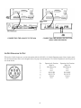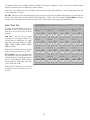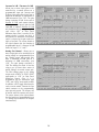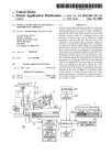
1
AS16x12
16 Channel Automatic Matrix Mixer
OPERATING INSTRUCTIONS
and trouble-shooting guide
INTRODUCTION
The AS16x12 is the most advanced automatic matrix mixer available today. Combining 16 automatic input channels, 12
output channels, and a full crosspoint matrix system into 2 rack spaces, the AS16x12 is a compact solution for a wide variety
of sound system applications. 15 nonvolatile preset memory positions mean complete flexibility and reconfigurability.
The 16 automatic inputs utilize the patented Proportional Gain plus Autoskew mixing algorithm* for seamless automatic
mixing performance. Input preamp gains include +50dB and +30dB for both dynamic and electret microphones, and 0dB
for line level inputs. Gain trim range on the inputs is +15dB to -63dB plus off.
The crosspoint matrix allows any input (or combination of inputs) to be routed to any output (or combination of outputs).
Available crosspoint gains include -15dB, -10dB, -5dB, 0dB, +3dB, +6dB, and off. In addition to the 16 inputs, matrix
sources include the audio from the LecNet Expansion connector as well as an internal noise source.
The 12 outputs are balanced line level. Outputs 9-12 each have a mic/line level switch to make those outputs compatible
with mic level devices like some four channel tape recorders.
The AS16x12 features a wealth of programmable features. With 17 programmable inputs and 19 programmable outputs,
even the most sophisticated control schemes are straightforward. The programmable inputs can control input or output level
on any grouping of inputs or outputs, memory preset recall, matrix crosspoint switching, or various functions associated
with the built-in room combining capability. Programmable outputs can indicate either input channel activity or the current
state of a programmable input.
The AS16x12 has an RS-232 port for remote setup or control by a computer or other RS-232 compatible controller. More
than one AS16x12 may be coupled together for larger applications.
TABLE
OF
CONTENTS
INTRODUCTION . . . . . . . . . . . . . . . . . . . . . . . . . . . . . . . . . . . . . . . . . . . . . . . . . . . . . . . . . . . . . . . . . . . . . . . . 2
GENERAL TECHNICAL DESCRIPTION . . . . . . . . . . . . . . . . . . . . . . . . . . . . . . . . . . . . . . . . . . . . . . . . . . . . . . . .3
INSTALLATION . . . . . . . . . . . . . . . . . . . . . . . . . . . . . . . . . . . . . . . . . . . . . . . . . . . . . . . . . . . . . . . . . . . . . . . . . . 4
FRONT PANEL DESCRIPTION . . . . . . . . . . . . . . . . . . . . . . . . . . . . . . . . . . . . . . . . . . . . . . . . . . . . . . . . . . . . . . . 7
REAR PANEL DESCRIPTION . . . . . . . . . . . . . . . . . . . . . . . . . . . . . . . . . . . . . . . . . . . . . . . . . . . . . . . . . . . . . . . 8
OPERATING INSTRUCTIONS . . . . . . . . . . . . . . . . . . . . . . . . . . . . . . . . . . . . . . . . . . . . . . . . . . . . . . . . . . . . . . 9
AS16x12 CONTROL PANEL SOFTWARE . . . . . . . . . . . . . . . . . . . . . . . . . . . . . . . . . . . . . . . . . . . . . . . . . . . . . . . 12
TROUBLESHOOTING . . . . . . . . . . . . . . . . . . . . . . . . . . . . . . . . . . . . . . . . . . . . . . . . . . . . . . . . . . . . . . . . . . . . 27
FCC PART 15 NOTICE . . . . . . . . . . . . . . . . . . . . . . . . . . . . . . . . . . . . . . . . . . . . . . . . . . . . . . . . . . . . . . . . . . . 27
SERIAL CABLE WIRING DIAGRAMS . . . . . . . . . . . . . . . . . . . . . . . . . . . . . . . . . . . . . . . . . . . . . . . . . . . . . . . . . 28
SERIAL PORT COMMANDS AVAILABLE
. . . . . . . . . . . . . . . . . . . . . . . . . . . . . . . . . . . . . . . . . . . . . . . . . . . . . . 29
SPECIFICATIONS . . . . . . . . . . . . . . . . . . . . . . . . . . . . . . . . . . . . . . . . . . . . . . . . . . . . . . . . . . . . . . . . . . . . . . . 34
SERVICE AND REPAIR
. . . . . . . . . . . . . . . . . . . . . . . . . . . . . . . . . . . . . . . . . . . . . . . . . . . . . . . . . . . . . . . . . . . 35
RETURNING UNITS FOR REPAIR
. . . . . . . . . . . . . . . . . . . . . . . . . . . . . . . . . . . . . . . . . . . . . . . . . . . . . . . . . . . 35
WARRANTY . . . . . . . . . . . . . . . . . . . . . . . . . . . . . . . . . . . . . . . . . . . . . . . . . . . . . . . . . . . . . . . . . . . . . Back cover
* U.S. Patents 5,402,500 and 5,414,776
2
GENERAL TECHNICAL DESCRIPTION
The AS16x12 uses a straightforward analog signal path to provide excellent audio performance. This is coupled with a
sophisticated microcontroller to implement the automatic mixing, matrix control, room combining, and programmable
input and output functions. The Adaptive Level Proportional automatic mixing algorithm is used by the AS16x12. This
algorithm uses the signal level pattern at the microphones to derive a pattern of channel gains. For instance, if only one
microphone channel is being spoken into, its level is dominant and that channel gets most of the system gain, while all other
channels are turned down. If more than one microphone is active, they share system gain according to their relative levels.
A “skewing” function gives some advantage to microphones which are active over time, to minimize interruptions from
transient noise at other microphones. Since the gain of each channel is apportioned continuously based on its relative level,
no abrupt gain changes are made. This makes the automatic action virtually inaudible.
Figure 1 shows the simplified block diagram of the AS16x12. The microphone preamp is a low-noise discrete design, which
is extensively RF protected. The preamp has three gain settings. The 0dB setting allows an input to accept line level signals,
while the +30dB and +50dB gain settings accommodate both low and high sensitivity microphones. Switchable 15V
Phantom power is provided for each channel.
Following the mic preamp, the audio
signal passes through a high quality
Voltage Controlled Amplifier (VCA).
This VCA, controlled by a signal from
the system D/A converter, is used to
implement both static gain control
(i.e. mic trim and remote input level)
and gain reduction for the automatic
mixing function. A Channel On LED
indicates which inputs are currently
active. A sweepable low-cut filter and
a shelving high frequency filter
provide tone control for each input.
The 16 inputs are routed through an
18 in / 12 out crosspoint matrix. The
matrix has multiple crosspoint gains
to accommodate the most com-plex
signal routing needs. Aside from the
16 inputs, the matrix also includes
two other inputs: a noise generator
and the input signal from the LecNet
Expansion In rear panel connector.
Signals from the Expansion In and
Expansion Out connectors allow easy
interface to AS8 mixers. In addition, a
Mix Minus signal is available which
allows easy interfacing to teleconferencing hybrids like the TH3A.
AS16x12 BLOCK DIAGRAM
SERIAL BUS
MAIN IN
MIX MINUS OUT
INPUT #1 (OF 16)
PROCESSOR
CONTROLLED
SWITCH
ARRAY
+15V
CHANNEL ON
AUDIO
VCA
MIC IN +
VARIABLE LOW CUT
HIGH CUT/BOOST
MIC
PREAMP
MIC IN -
MIC GND
FROM D/A
CONVERTER
PREAMP GAIN
0 dB (LINE)
+30 dB (MIC)
+50 dB (MIC)
SPEECH
FILTER
LOG
➔
CONVERTER
TO AVD
CONVERTER
AUTO MIX
LOG IN
FROM INPUT 2
FROM INPUT 3
FROM INPUT 4
FROM INPUT 5
FROM INPUT 6
FROM INPUT 7
FROM INPUT 8
FROM INPUT 9
FROM INPUT 10
FROM INPUT 11
FROM INPUT 12
FROM INPUT 13
FROM INPUT 14
FROM INPUT 15
FROM INPUT 16
SERIAL BUS
MAINOUT
MIX MINUS IN
> - PROGRAMMABLE INPUT 1
> - PROGRAMMABLE INPUT 2
> - PROGRAMMABLE INPUT 3
> - PROGRAMMABLE INPUT 4
> - PROGRAMMABLE INPUT 5
> - PROGRAMMABLE INPUT 6
> - PROGRAMMABLE INPUT 7
> - PROGRAMMABLE INPUT 8
> - PROGRAMMABLE INPUT 9
> - PROGRAMMABLE INPUT10
> - PROGRAMMABLE INPUT 11
> - PROGRAMMABLE INPUT12
> - PROGRAMMABLE INPUT13
> - PROGRAMMABLE INPUT14
> - PROGRAMMABLE INPUT15
> - PROGRAMMABLE INPUT16
> - PROGRAMMABLE INPUT17
AUTO MAX
LOG OUT
LECNET PORT
(RS-232)
PROCESSOR
CONTROLLED
VARIABLE
RESISTOR
PROCESSOR
CONTROLLED
VARIABLE
RESISTOR
RX
A/C
CONVERTER
NOM IN 1
NOM IN 2
NOM IN 3
NOM IN 4
NOM IN 5
NOM IN 6
NOM IN 7
NOM IN 8
AUDIO EXP IN
D/A
CONVERTER
< - PROGRAMMABLE INPUT 1
< - PROGRAMMABLE INPUT 2
< - PROGRAMMABLE INPUT 3
< - PROGRAMMABLE INPUT 4
< - PROGRAMMABLE INPUT 5
< - PROGRAMMABLE INPUT 6
< - PROGRAMMABLE INPUT 7
< - PROGRAMMABLE INPUT 8
< - PROGRAMMABLE INPUT 9
< - PROGRAMMABLE INPUT10
< - PROGRAMMABLE INPUT 11
< - PROGRAMMABLE INPUT12
< - PROGRAMMABLE INPUT13
< - PROGRAMMABLE INPUT14
< - PROGRAMMABLE INPUT15
< - PROGRAMMABLE INPUT16
< - PROGRAMMABLE INPUT17
< - PROGRAMMABLE INPUT18
< - PROGRAMMABLE INPUT19
NOISE
SOURCE
EXPANSION OUT
(MINI DIN JACK)
TX
uC
68HC12
1 OF 16
EXPANSION IN
(MINI DIN JACK)
NOM TOTAL 1
NOM TOTAL 2
NOM TOTAL 3
NOM TOTAL 4
NOM TOTAL 5
NOM TOTAL 6
NOM TOTAL 7
NOM TOTAL 8
NOM TOTAL 1
NOM TOTAL 2
NOM TOTAL 3
NOM TOTAL 4
NOM TOTAL 5
NOM TOTAL 6
NOM TOTAL 7
NOM TOTAL 8
D/A
CONVERTER
PROCESSOR
CONTROLLED
VARIABLE
RESISTOR
Σ
10 dB
Σ
10 dB
Σ
10 dB
Σ
10 dB
NOM OUT 1
NOM OUT 2
NOM OUT 3
NOM OUT 4
NOM OUT 5
NOM OUT 6
NOM OUT 7
NOM OUT 8
BALANCED
MIC/LINE OUTPUT 1
BALANCED
MIC/LINE OUTPUT 2
BALANCED
MIC/LINE OUTPUT 3
BALANCED
MIC/LINE OUTPUT 4
BALANCED
MIC/LINE OUTPUT 5
BALANCED
MIC/LINE OUTPUT 6
BALANCED
MIC/LINE OUTPUT 7
BALANCED
MIC/LINE OUTPUT 8
Σ
Σ
Σ
An RS-232 port is available to allow
many of the functions of the
AS16x12 to be controlled either by a
computer or a dedicated control
system (such as the AMX® or
Crestron™ systems).
Σ
Σ
10 dB
MIC/LINE
SWITCH
BALANCED
MIC/LINE OUTPUT 9
Σ
10 dB
MIC/LINE
SWITCH
BALANCED
MIC/LINE OUTPUT 10
10 dB
MIC/LINE
SWITCH
BALANCED
MIC/LINE OUTPUT 11
10 dB
MIC/LINE
SWITCH
BALANCED
MIC/LINE OUTPUT 12
Σ
Σ
PROCESSOR
CONTROLLED
ATTENUATORS
3
AUDIO EXP OUT
INSTALLATION
Because it is so highly integrated, the AS16x12 is straightforward to install. The following sections explain the installation
and wiring, as well as the software setup of the AS16x12.
AS16X12 AUDIO INPUTS
Each of the 16 AS16x12 inputs is balanced, and provides 15V
phantom power (through 2K ohm feed resistors to the “+” and
“-” input connections). Phantom power is switchable on a perchannel basis. The drawing to the right shows two examples
of line level interface with the AS16x12; one, an unbalanced
line level source and the other, a balanced line level source.
Unbalanced Line Level Source
Balanced Line Level Source
AS16X12 AUDIO OUTPUTS
Each of the 12 AS16x12 outputs is balanced, and outputs 9 - 12 may be set for line or microphone level output. To use an
output in the unbalanced line level mode, take the signal from the “+” output connection and the output ground. Leave
the “-” output floating. To use outputs 9 - 12 in the unbalanced microphone level mode, take the signal from the “+” output
connection and the output ground. In this case, you should connect the “-” output to ground. Be sure that the MIC/LINE
switch is in the MIC (down) position for the desired output.
AS16X12 PROGRAMMABLE INPUTS
The AS16x12 has 17 programmable inputs which can control a variety of AS16x12 parameters. Each input can respond to
either a contact closure or a continuous voltage. The diagram to the right shows common connections to the programmable
input pins.
Pot Connection for Analog Control of Gain
Contact Closure as Programmable Input
DC Voltage source as Programmable Input
Each programmable input is internally pulled up through a 100K resistor to +5V, so no external pull up resistors are
necessary. When using a continuous voltage with one of the programmable inputs, the Function of the programmable input
must be set to either Analog In Control or Analog Out Control. See the Programmable Input tab in the AS16x12 Control
Panel software for setting all programmable input parameters.
AS16X12 PROGRAMMABLE OUTPUTS
The AS16x12 has 19 programmable
outputs which can indicate either
channel activity or the current state
of a programmable input. Each
programmable output is the electrical
equivalent of a contact closure to
ground. When a programmable
output is “active”, it conducts
current to ground. When the
programmable output is “inactive”,
no current flows to ground. The
maximum usable voltage for the
program-mable outputs is 40V, and
they will safely conduct up to
100mADC continuous. The diagram
on the right shows some typical uses
for the programmable outputs.
LED is on when the programmable output is active
4
LED is off when the programmable output is active
It is permissible to run LEDs from the +5VDC pins on the programmable input connector, as long as the total LED current
for all LEDS on does not exceed 100mA. Similarly, 5V relay coils may also be run from the +5VDC pins on the
programmable input connector, as long as the total coil current for all relays on does not exceed 100mA. Note that the
diagram shows an external DC source powering the relay coil. This will be necessary if coil voltages above 5V are needed.
AUDIO EXPANSION IN/OUT
When multiple AS16x12s are used in an application, their Audio Expansion ports must be interconnected using the Audio
Expansion In/Out connectors on the rear panel of the AS16x12. These two 30 pin headers are just to the right of the LecNet
(RS232) jack on the rear panel. A 3" 30 conductor ribbon cable is supplied with each AS16x12 for this purpose. When
installing the AS16x12s in a rack, the Master AS16x12 should be mounted in the top of the rack, with Slave AS16x12s
mounted below the Master AS16x12. The ribbon connector then connects the Audio Expansion In connector of the Master
AS16x12 to the Audio Expansion Out connector of the first Slave AS16x12. If there are more than one Slave AS16x12s,
the Audio Expansion In connector of the first Slave AS16x12 is connected to the Audio Expansion Out connector of the
second Slave AS16x12, and so on for as many Slave AS16x12s as exist in the system.
AS16x12 Rear Panel
TH3A Rear Panel
To additional AM16x12s
CONNECTING MULTIPLE AS16X12S TOGETHER
CONNECTING THE AS16X12 TO THE TH3A
5
CONNECTING THE AS16X12 TO THE AS8
CONNECTING THE AS16X12 TO THE TH3A
AND A VIDEO RECORDER
LECNET EXPANSION IN/OUT
When other LecNet devices are used in conjunction with the AS16x12s, the LecNet Expansion ports of these devices must
also be interconnected. Refer to the diagrams above for proper interconnections. The LecNet Expansion In and Out pinouts
are shown below.
Pin
1
2
3
4
5
6
7
8
6
Expansion In Function
Main In
Mix Minus Out
N/C
N/C
RS-232 RX
RS-232 TX
Ground
N/C
Expansion Out Function
Main Out
Mix Minus In
N/C
N/C
RS-232 RX
RS-232 TX
Ground
N/C
FRONT PANEL DESCRIPTION
CHANNEL ACTIVITY LEDS - Indicates channel activity. The LEDs light when the attenuation applied by the automatic
mixing algorithm is less than or equal to 6dB. The indication of channel activity is responsive to the Input Qualification and
Output Hold time parameters, which may be set in the Miscellaneous tab of the AS16x12 control panel.
RESET DEFAULTS button - This button will reset the unit to factory defaults when held down while the power switch
is turned on.
AS16X12 FRONT PANEL
7
REAR PANEL DESCRIPTION
MIC/LINE INPUTS 1-16 - Accepts balanced or unbalanced signal. Fully balanced differential input, RF filtered.
GAIN SELECTION SWITCHES 1-16 - Allows input channel gain to be set. 0dB gain, for line level sources, is set when
both switches of the pair are in the up position. 30dB gain, typically for high output (electret) microphones, is set when the
left switch is in the up position and the right switch is in the down position. 50dB gain, used for low output (dynamic)
microphones, is set when both switches are in the down position.
LINE OUTPUTS 1-12 - Provide balanced system outputs. The Line Outputs may also be used in an unbalanced mode by
connecting the “+” terminal of the Line Output to the signal lead of the unbalanced device, and the ground terminal of the
Line Output to the ground of the unbalanced device. See “AS16x12 Audio Outputs” on page 4 for more information on
connecting the outputs in balanced and unbalanced mode.
MIC/LINE SWITCHES 9-12 - Introduces 40dB of attenuation into the associated line outputs 9-12. This yields the
appropriate signal levels to interface with mic level devices.
PROGRAMMABLE INPUTS - Allows remote control of a number of AS16x12 functions.
Each of the 17 programmable inputs can utilize either continuous DC voltages (0VDC5VDC) or contact closures, depending on the particular function chosen. For continuous
voltages, either a 10K ohm linear pot or an adjustable DC control voltage may be used. The
volume control action is internally scaled in software, giving an “audio-taper” characteristic
to a linear pot. When using a DC control voltage, the control constant is 0.167V/dB (or
6dB/V) from 0V to 5V. At 0V, the channel is turned completely off. The control voltage
should not exceed 5V.
PROGRAMMABLE OUTPUTS - Allows indication of either channel activity or
programmable input states. Each of the 19 programmable inputs is the electronic equivalent
of a contact closure. The logic output will sink up to 100mA at voltages up to 40VDC,
however, the total current draw of all logic outputs should not exceed 100mA if the internal
+5V supply is used.
AUDIO EXPANSION IN/OUT - Allows multiple AS16x12s to be linked together when more than 16 inputs are needed.
In multiple AS16x12 setups, one AS16x12 is set to be the Master, and all others are set to be Slaves. The Audio Expansion
In of the Master AS16x12 is connected to the Audio Expansion Out of the first Slave AS16x12, using the supplied 30 pin
ribbon cable. The Audio Expansion In of the first Slave AS16x12 is connected to the Audio Expansion Out of the next Slave
AS16x12, and so on.
RS-232 SERIAL PORT - Provides access to and control of some of the operational features of the AS16x12. The port is
compatible with the serial port of a PC, or other controllers with RS-232 type serial ports. For hardware interconnection
and software details, see Appendix 1, “Serial Port Hardware and Software”.
EXPANSION IN/OUT - Allows other LecNet devices to be connected to the AS16x12. Also used when multiple
AS16x12s are connected together to bus the RS-232 serial connection between AS16x12s.
MASTER/SLAVE SWITCH - Sets the AS16x12 for use as a Master device or a Slave device. AS16x12s used singly should
be set for Master mode operation.
PWR IN - Connects to the PS60 power supply to provide power for the AS16x12.
PHANTOM POWER SWITCHES - Allow +15V phantom power to be applied or not on a per-channel basis.
AS16X12 REAR PANEL
9
OPERATING INSTRUCTIONS
Since most of the parameters used to set up the AS16x12 are adjusted using the AS16x12 Software Control Panel, the
operating instructions include instructions for the use of the software. It is recommended that you have the software
running, either live or in the demo mode, as you read through this section.
Power Up
When the AS16x12 is powered on, it automatically loads the active setup from Preset 1. Therefore, you should always store
the desired power--up setting for the AS16x12 in Preset 1.
Master/Slave Switch
The Master/Slave switch should be set to the Master position if only one AS16x12 is being used. When multiple AS16x12s
are used in a system, only one is set to Master and the rest are set to Slave. See also the wiring descriptions of the Audio
Expansion In/Out and Expansion In/Out connectors in the Installation section.
Input Preamp Gain
Input preamp gain is set using the dip switches just to the left of each 5 pin input connector. Dip switch settings for 0dB,
+30dB, and +50dB input gain are shown on the rear panel of the AS16x12. Generally, the +50dB position is used for all
dynamic microphones and electret microphones where the working distance from the microphone will be greater than
about 18 inches. The +30dB position is useful for electret microphones with working distances less than 18 inches and most
wireless microphones. The 0dB setting is for line level sources. Remember to switch phantom power on for electret
microphones and off for dynamic mics or line level sources.
Output Mic/Line Switch (Outputs 9 - 12)
Outputs 9 through 12 may be either Mic or Line level outputs. The dip switch between the output connectors for outputs
9/10 and 11/12 controls the output level. There is approximately 40dB of attenuation introduced in the Mic position
relative to the Line position.
Using the AS16x12 Software Control Panel
The AS16x12 software control panel may be used in one of two ways. When launched from the LecNet Master Pro
application, you can control all the parameters of the AS16x12 in real time. (Your PC must be connected to the AS16x12
using the supplied LecNet serial cable in order for this to happen.) Alternatively, you can launch the AS16x12 control panel
directly and it will automatically come up in the demo mode. The demo mode is useful for doing system setup (and saving
the setups to a disk file) without the need to be connected to an AS16x12.
System setup follows the order of the tabs on the control panel. Start at the left tab and work your way to the right. The
only exception to this is when you are using room combining. In this case, after setting up the input gain and input tone
controls, go directly to the room combining tab. Please refer to the AS16x12 Control Panel Software section of this manual
for a complete description of each control panel tab.
The diagram below represents the signal flow of one input to one output through one matrix crosspoint. Illustrated are all
the gain control points in the signal path.
To adjust this parameter:
Use this control:
Mic Preamp Gain
Input Gain
Rear Panel (Input) Gain
Output Gain
Rear Panel (Output) Gain
Rear panel dip switches
Input gain tab on AS16x12 control panel software
Programmable inputs on AS16x12 rear panel
Output gain tab on AS16x12 control panel software
Programmable outputs on AS16x12 rear panel
9
Input Gain Tab
Each input channel has two gain control points, in addition to the rear panel preamp gain switches. The input control point
labeled “Input Trim” is adjusted using the Input Gain tab on the AS16x12 control panel. This control is used to adjust the
sensitivity of each microphone or line level input to the desired gain. The gain adjustment range is +15dB to -63dB plus off.
You may want to increase the mic preamp gain if you find that your input gain settings are routinely above +10dB.
The input control point labeled “Rear Panel” represents the gain adjustments which can be made from the rear panel
programmable inputs. The rear panel gain control is attenuation only, starting at a maximum gain of 0dB. The rear panel
input gain controls may be limited in their adjustment range using the Miscellaneous Settings tab on the AM16/ 12 control
panel. In addition, you may set a rear panel preset gain value that will be applied to any outputs which are being controlled
by a programmable input. The preset gain is applied at power up or when sub-rooms are combined or uncombined (using
the room combining capabilities of the AS16x12). Note that if there are no limits applied to the rear panel gain range, the
input channel may be turned completely off. The current gain value of the rear panel controls is displayed on the
Miscellaneous Settings tab.
Output Gain Tab
The output gain structure is identical to the input gain structure, with the exception that the Output Gain range is +10dB
to -68dB plus off. The output gain is adjusted using the Output Gain tab.
Matrix Setup Tab
Matrix crosspoint gain can be set using the Matrix tab. Input-to-output gains are set based on the requirements of the
application. For example, you can set up a “mix-minus” sound reinforcement system when you are using multiple microphones
and overhead distributed speakers. Each speaker (or small group of speakers) would be fed from its own mix of microphones.
A given speaker’s mix would consist of all microphones not physically close to the speaker, while excluding those microphones
which are close to the speaker. The possibility of feedback is greatly reduced when this approach is repeated with all system
speakers. A multichannel amplifier may be used to power each speaker individually.
Programmable Inputs Tab
Programmable inputs may be set up using the Programmable Inputs tab. Below is a short list of typical applications for each
of the programmable input functions available:
Analog In Control: Used to control the input gain of one or more inputs with a potentiometer or DC voltage source.
Additionally, a toggle switch can be used as a mute switch by shorting the programmable input to ground for mute.
Increase In 1dB, Decrease In 1dB: Used to control the input gain of one or more inputs with momentary switch closures.
Each switch closure will increase or decrease the gain of the associated input(s) by 1dB. If the switch is pushed and held,
it will continue to increment or decrement until the switch is released or the gain reaches its high or low limit.
Analog Out Control: Used to control the output gain of one or more inputs with a potentiometer or DC voltage source.
Additionally, a toggle switch can be used as a mute switch by shorting the programmable input to ground for mute.
Increase Out 1dB, Decrease Out 1dB: Used to control the output gain of one or more inputs with momentary switch
closures. Each switch closure will increase or decrease the gain of the associated input(s) by 1dB. If the switch is pushed
and held, it will continue to increment or decrement until the switch is released or the gain reaches its high or low limit.
Memory Preset: Used to recall one of the 15 AS16x12 preset memories with a momentary switch closure. Remember to
save the same memory preset associations in all the AS16x12 memory preset positions you’ll be using. You can also assign
a programmable output to reflect the programmable input state of the programmable inputs you’re using for memory preset
recall to drive LEDs for visual feedback of the current memory preset.
Toggle Crosspoint Gain: Used to temporarily apply the signal from any one of the 16 inputs to any combination of outputs
using a momentary switch closure to toggle the state of the affected crosspoints. Useful for zone paging applications, etc.
10
Mute In: Used to mute one or more inputs with a switch closure. Subsequent contact closures toggle between mute and
unmute. You can also assign a programmable output to reflect the programmable input state of the programmable inputs
you’re using for input muting to drive LEDs for visual feedback of the mute/unmute state of the inputs.
Mute Out: Used to mute one or more outputs with a switch closure. Subsequent contact closures toggle between mute
and unmute. You can also assign a programmable output to reflect the programmable input state of the programmable inputs
you’re using for output muting to drive LEDs for visual feedback of the mute/unmute state of the outputs.
Toggle Room Boundary: Used when room combining is active to connect the boundaries (using a momentary switch
closure) of two rooms and combine their sound systems. This option is not available in the Programmable Inputs tab, but
is set automatically by the AS16x12 control panel when the room combining function is active.
Not Used: Unassigns a programmable input from any system function.
PROGRAMMABLE OUTPUTS TAB
Programmable outputs may be set up using the Programmable Outputs tab. Below is a short list of typical applications for
the two programmable output functions available:
Input Channel Activity: Used to indicate when one or more channels are active. This function may be used for videofollow-audio applications, where each programmable output indicates activity on one or more channels. The programmable
outputs are connected to logic inputs on a video switcher to switch between cameras.
Programmable Input State: Used to provide user feedback for certain programmable input functions. A programmable
output whose function is Programmable Input State will be active (i.e. conducting to ground) or inactive (i.e. open) as
follows depending on the function of the programmable input with which it is associated:
Function
State when LED On
State when LED Off
Analog In Attenuation
Increase In 1dB:
Decrease In 1dB:
Analog Out
Increase Out 1dB:
Decrease Out 1dB:
Memory Preset:
Toggle Crosspoint Gain:
Mute In:
Mute Out:
< 15dB
Contact closure on prog input
Contact closure on prog input
Attenuation < 15dB
Contact closure on prog input
Contact closure on prog input
Associated memory is active
Input-to-output(s) connection made
Associated input(s) not muted
Associated output(s) not muted
Attenuation > 15dB
No contact closure on prog input
No contact closure on prog input
Attenuation > 15dB
No contact closure on prog input
No contact closure on prog input
Associated memory is not active
Input - output(s) connection not made
Associated input(s) muted
Associated output(s) muted
Room Combining Tab
If your application requires room combining, the Room Combining tab description in the AS16x12 Control Panel Software
section provides full setup information.
Miscellaneous Settings Tab
Adjustments or limitations to the front and rear panel gain controls, setup of the input qualification time and output hold
time, or configuration of the Expansion port mix-minus signal may be accomplished in the Miscellaneous Settings tab. When
multiple AS16x12s are used in a system, set the Internal NOM bus link to Expansion In/Out option on all slave AS16x12s
to No Link.
When all tabs are set appropriately for the application, the system is ready to use.
11
AS16X12 CONTROL PANEL SOFTWARE
The following section is a description of the File menu and each of the tabs in the AS16x12 Control Panel application.
FILE MENU OPTIONS
Copy Preset(s) to AS16x12 from Disk File... - Allows any preset stored to a disk file (.amd file extension) to be loaded
to the corresponding AS16x12 memory preset. The Preset 1 through Preset 15 selections copy a single preset, while the All
Presets selection copies all 15 presets to the AS16x12. After a preset is loaded to the AS16x12, it will be transferred to the
active AS16x12 setup. If all 15 presets are loaded, preset 1 will be made the active preset. This option is helpful in restoring
AS16x12 settings if they have been accidentally corrupted. Note that this option will overwrite any data stored in the
AS16x12’s preset memory with the new preset data from disk.
Save Preset(s) from AS16x12 to Disk File... - Allows any preset currently stored in the AS16x12’s preset memory to
be saved to a disk file. The Preset 1 through Preset 15 selections copy a single preset, while the All Presets selection copies
all 15 AS16x12 presets to the selected disk file. This option is helpful in archiving the final settings for the AS16x12 in a
particular installation.
Load Active Setup from Disk File... - Allows the active AS16x12 setup to be loaded from a disk file. Loading the active
AS16x12 setup from a disk file will not overwrite any AS16x12 preset memory data. This option is helpful when a basic
AS16x12 setup has been generated off-site and needs to be “tweaked” on-site.
Save Active Setup to Disk File... - Allows the active AS16x12 setup to be stored to a disk file. You select which preset
position in the disk file to which to store the active AS16x12 setup. This option has no effect on the AS16x12 preset
memories.
Select Active Setup from AS16x12 Preset... - Allows any of the AS16x12 preset memories to be recalled and made to
be the active AS16x12 setup. This option does not affect any of the preset memory data.
Save Active Setup to AS16x12 Preset... - Allows the active AS16x12 setup to be stored in one of the 15 preset memories
in the AS16x12. Note that this option will overwrite any preset memory data stored in the selected preset memory position.
Enter Input/Output Names... - Allows names to be assigned to the 16 inputs and the 12 outputs of the AS16x12. These
names may be up to 15 characters long and are stored in nonvolatile memory in the AS16x12. In addition, the names are
stored in any disk files generated with any of the save to disk options above. Inputs or outputs with no assigned names are
listed as “No Name”. To change a name, simply click on the desired text box and enter the desired name. While you are
permitted to enter more than 15 characters in the text box, only the first 15 will be stored. To save the changes to the
AS16x12’s nonvolatile memory, click the Apply button. If you click the Cancel button, the changes you have made will not
be applied. The shortcut key for this option is Ctrl+E.
Enter Disk File Notes... - Allows you to add any notes that
you want to be included in a file saved to disk. These notes
could be installation instructions, operational instructions, or
any other information which might be helpful to associate
with a saved file. You’ll see the screen shown at the right
when you choose this option:
After you enter the desired text into the text box, choose OK
to save the changes you’ve made. Cancel will ignore the
changes you’ve made since the last time you clicked OK. Note
that to save your changes to a disk file, you must still either use
Save Preset(s) from AS16x12 to Disk File... or Save Active
Setup to Disk File... to store the notes in a disk file. The
shortcut key for this option is Ctrl+D.
Print Setup... - Allows the active printer to be changed using
the standard Windows printer setup dialog. This will set the
printer which is used with the Print Tabs... menu selection.
The shortcut key for this option is Ctrl+P.
Print Tabs... - Allows any or all of the AS16x12 control panel tabs to be printed for documentation purposes.
12
Update AS16x12 Firmware from Disk File - Allows newer firmware revisions to be loaded into the AS16x12. From
time to time, new features or bug fixes will be added to the AS16x12’s firmware. These changes will be distributed with
the LecNet installation disks and available on the Lectrosonics Web site (www.lectrosonics.com). The firmware file will have
a “.s19” extension. When installing from the installation disks, the firmware files will automatically be placed in the LecNet
directory (default: c:\lecnet). If new firmware is downloaded from the Web site, the file should be placed in the LecNet
directory.
Any time the AS16x12 Control Panel is run, it will check for .s19 firmware files which are more recent than the firmware
revision in the AS16x12. You will be alerted that the AS16x12’s firmware can be updated, and you can select whether or
not to let the update proceed. If no firmware file is available in the LecNet directory, this option will be disabled. The
shortcut key for this option is Ctrl+U.
Exit - Ends the application. The shortcut key for this option is Ctrl+X.
Important note: If you will be using the Room Combiner functions of the AS16x12, proceed to the instructions for the
Room Combining Tab on page 23.
INPUT GAIN TAB
The Input Gain tab allows the input gain,
Auto/Direct status, and the NOM bus
association to be set for each of the 16
input channels.
Gain - Allows the input gain level to be
trimmed between +15dB and -63dB, or
Off. The gain shown in the associated box
should be added to the preamp gain (set
by rear panel dip switches) to calculate
the total channel gain. For example, if the
rear panel dip switches for an input are
set such that the preamp gain is +30dB,
and the input gain box shows +5dB, the
total gain applied to that input channel
(excluding matrix crosspoint and output
gain) would be +35dB. The background
color of the input gain box will change
from white to red if the input is muted by
actuation of the Mute Input function of a
programmable input. The input gain scroll
bar will also be disabled while the
channel is muted.
Short Cuts: A left mouse click on the gain box will set the input gain to 0dB, while a right mouse click will set the input
gain to Off.
Auto/Direct Input Status - Each input may be in either Auto or Direct mode. An input in the Auto mode responds to the
NOM bus to which it is assigned to determine its instantaneous gain. An input in the Direct mode is always on and never
has any gain reduction applied to it from the automatic mixing action. An input in the Direct mode will, however, contribute
to the NOM bus to which it is assigned. In most cases, inputs connected to microphones should be set to Auto mode. Direct
mode is useful for line level sources.
NOM Bus - Sets the NOM bus association for each input. The AS16x12 has 8 NOM busses, and any input may be assigned
to any NOM bus, or to “None”. All inputs assigned to the same NOM bus act like a single automatic mixer, in that their
instantaneous gains are determined by the relative signal levels on all other inputs assigned to that NOM bus. By assigning
inputs to different NOM busses, more than one “virtual mixer” may be constructed. As a simple example, you might assign
inputs 1-8 to NOM bus 1 and inputs 9-16 to NOM bus 2. If inputs 1-8 were then sent to output 1 and inputs 9-16 were
sent to output 2 (using the Matrix tab), you would have two separate 8 input automatic mixers. With 8 NOM busses, up
13
to 8 separate mixers can be configured with the AS16x12. If an input is assigned to “None”, it will neither affect any other
channel’s automatic gain or be affected by another channel.
Short Cuts: A left mouse click on the NOM box will associate the input with NOM bus 1, while a right mouse click will
set the association to “None”.
On LED - Indicates that the attenuation applied to the input as a result of the automatic mixing action is less than 6dB. For
inputs in the Direct mode, or inputs whose NOM assignment is “None”, this LED is always lit. Level Meter - Indicates
the inputs level, taking into consideration the Input Gain, and the front and rear panel gain contributions.
INPUT TONE TAB
The Input Tone tab allows the low cut
frequency and the high frequency cut or
boost to be set for each of the 16 input
channels.
Low Cut - Sets the low cut corner
frequency for each input channel. The
low cut filter is a 6dB/octave (i.e. single
pole) filter. Frequency choices are 75Hz,
90Hz, 110Hz, 130Hz, 190Hz, 280Hz,
600Hz, and Flat.
Short Cut: A left click on the low cut box
causes the frequency to be set to “Flat”.
Hi Cut/Boost - Sets the high frequency
cut or boost for each input channel. The
inflection point of the high frequency tone
control is approximately 1kHz. Choices
for cut/boost are -8dB, -6dB, -3dB, Flat,
+3dB, +6dB, and +8dB.
Short Cut: A left click on the hi cut/boost
box causes the cut/ boost value to be set
to “Flat”.
14
MATRIX SETUP TAB
The Input/Output Matrix tab sets the
input to output assignments for the
AS16x12.
Input/Output Crosspoint -Allows the
input/output crosspoint gain to be set.
Each of the 12 rows of 18 crosspoint
boxes represent input connections which
may be set from inputs to outputs 1-12.
To set a crosspoint gain, simply click on
the crosspoint box at
the intersection of the
desired input and
desired output. The
crosspoint box will
turn yellow, and you’ll
see the following
selection box pop up:
Off
-15dB
-10dB
-5dB
-0dB
+3dB
+6dB
At this point, the current crosspoint gain is highlighted in the selection box. Choose a new gain by clicking on the desired
crosspoint gain value. If you decide not to change the crosspoint gain, you may press the Esc key or click on the crosspoint
box again to close the selection box without changing the crosspoint gain. The first 16 crosspoint boxes in each output row
are for the AS16x12 inputs. Two other signals are available to be included in the output mixes: Exp In and Noise.
Exp In is the signal from the 8 pin mini-DIN LecNet Expansion In connector on the rear panel of the AS16x12. This signal
would be used if another LecNet device, like a TH3A Telephone Hybrid, were connected to the AS16x12 via the expansion
cable. In this case, the TH3A’s receive signal would be present at the Exp In connector. The crosspoint gains for Exp In to any
active outputs would be set to the desired gain so that the participants in the local room could hear the far-end participant.
Another application might be the addition of 8 more inputs using an AS8. In this case, the sum of all 8 AS8 channels would
appear at the Exp In connector. This signal could then be distributed as necessary to appropriate output mixes.
The AS16x12 includes an internal broadband noise generator which can be included into any of the output mixes. One
application for the noise generator is bench conferences in courtrooms. During a bench conference, noise is output over the
sound system in the jury box, the gallery, and any other place that shouldn’t hear the conversation at the bench.
Short Cuts: A right mouse click on a crosspoint gain box will set the crosspoint gain to 0dB. A middle mouse click (for those
with a three button mouse) will set the crosspoint gain to “Off”.
Refresh Matrix (Ref) Button - Updates the crosspoint matrix display to indicate the active AS16x12 setup. This is useful
when the room combining function is in use, or any other function which might change the matrix crosspoint setup.
Clear Matrix (Clr) Button - Clears all matrix crosspoints to the “Off” state.
15
OUTPUT GAIN TAB
The Output Gain tab allows the output
gain levels to be set.
Gain, Outputs 1 - 12 - Allows the
output gain to be set between +10dB
and -68dB or “Off”. The background
color of the output gain box will change
from white to red if the output is muted
by actuation of the Mute Output
function of a programmable input. The
output gain scroll bar will also be
disabled while the output is muted.
Short Cuts: A left mouse click on the
gain box will set the output gain to 0dB,
while a right mouse click will set the
output gain to Off.
Master Output Section - The Master
Output section provides a convenient
way to apply gain changes to more than
one output at a time. The six buttons
(Set to Off, Set to 0dB, Decrease by 1dB, Increase by 1dB, Decrease by 5dB, and Increase by 5dB) facilitate several common
gain manipulations. Their action is applied to any output whose check box is checked. The Select All and Unselect All
buttons provide a quick way to apply gain changes to all channels simultaneously. Note that the Increase and Decrease
buttons are push-and-hold, and will increment or decrement the output gain for as long as they are held down.
PROGRAMMABLE INPUTS TAB
The AS16x12 has 17 programmable
inputs (available on the 25 pin D-Sub
connector on the rear panel) which
allow control of a wide variety of
AS16x12 functions. Only the parameters
in the “Applies To” section which are
associated
with
each
specific
programmable input function will be
enabled as you select different functions.
All other parameters are disabled. This
eliminates invalid Function/Applies To
settings. Each of the available functions
is explained below.
Hint: If the function (or any associated
inputs, outputs, etc.) of a programmable
input is changed on the control panel,
the Apply button will be enabled. The
Apply button is located in the lower right
hand corner of the Programmable Input
tab. The Apply button must be clicked
before any changes are actually applied to the active AS16x12 setup. Note that you should use the Select Programmable
Input buttons to select the programmable input you’d like to configure before doing any configuration.
Select Programmable Input Buttons 1-17 - Allows selection of which programmable input to change. Note that the
frame caption “Programmable Input ...” (upper left in blue) will change to indicate the programmable input currently being
changed.
16
Push Input Button - Allows a contact closure to be simulated for the current programmable input. This is useful when
testing to see that the changes you’ve made to each programmable input indeed have the intended effect. Each click on the
“Push Input...” button has the same effect as a momentary contact closure on the current programmable input. Note that
the caption on the Push Input button always reflects the current programmable input. The Push Input button will be
disabled for the Analog In Control, Analog Out Control and Not Used options.
Programmable Input Status “LED” - Shows the current state of a programmable input. The status indicator only has
meaning for the following programmable input functions:
Function
State when LED On
State when LED Off
Analog In Control
Increase In 1dB:
Decrease In 1dB:
Analog Out Control
Increase Out 1dB:
Decrease Out 1dB:
Memory Preset:
Toggle Crosspoint Gain:
Mute In:
Mute Out:
Attenuation < 15dB
Contact closure on prog input
Contact closure on prog input
Attenuation < 15dB
Contact closure on prog input
Contact closure on prog input
Associated memory is active
Input-to-output(s) connection made
Associated input(s) not muted
Associated output(s) not muted
Attenuation > 15dB
No contact closure on prog input
No contact closure on prog input
Attenuation > 15dB
No contact closure on prog input
No contact closure on prog input
Associated memory is not active
Input - output(s) connection not made
Associated input(s) muted
Associated output(s) muted
Apply Button - Applies the current setting of “Function” and “Applies To” to the current programmable input. When the
Apply button is enabled, this indicates that the setting of “Function” and “Applies To” in the AS16x12 does not match the
setting of “Function” and “Applies To” shown on the control panel screen. Clicking the Apply button will load the control
panel setting into the active AS16x12 setup. This does not store the changes to a memory preset! That must be done
explicitly from the File/Save Active to AS16x12 Preset... file menu option. If changes are made to a programmable input
but not applied (by clicking on the Apply button), and another programmable input is selected (by clicking another of the
Select Programmable Input buttons), all the changes to the first programmable input which were not applied will be lost.
PROGRAMMABLE INPUT FUNCTIONS:
Analog In Control - Allows one or more input gains to be controlled by an analog voltage on a programmable input pin.
Analog input gain control goes from a maximum of 0dB gain to a minimum of 30dB attenuation, plus “Off”. The gain
change resolution is 1dB. The Analog In Control mode is ideal for using a pot (or some other source of analog voltage) to
control input gain. The valid voltage range in the Analog In mode is 0VDC to 5VDC. 0VDC corresponds to “Off” (or Rear
Panel Minimum Input Gain, if it is programmed for less attenuation than “Off”), and +5VDC corresponds to 0dB. In
addition, a SPST toggle switch may be
used as a mute switch. Connect the two
switch contacts to the programmable
input pin and ground. The inputs will be
muted when the contacts are closed.
The screen shown to the right indicates
that the function of programmable input
1 is analog input control of inputs 1, 2,
3, 5, and 7. Notice how multiple inputs
may be controlled by a single
programmable input.
17
Increase In 1dB / Decrease In 1dB Allows one or more input gains to be
controlled by a contact closure on a
programmable input pin. Increase and
Decrease input gain control goes from a
maximum of 0dB gain to a minimum of
30dB attenuation, plus “Off”. The gain
change resolution is 1dB. In the case of
Increase In 1dB, each contact closure
will increment the input(s) gain by 1dB
until 0dB is reached. Decrease In 1dB
will decrement the input(s) gains by 1dB
until either “Off” or Rear Panel
Minimum Input Gain is reached. If the
contact closure is pushed and held, it
will continue to increment or decrement
until it is released or the gain reaches its
high or low limit. The screen shown to
the right indicates that the function of
programmable input 1 is Increase In 1dB
control of inputs 1, 2, 3 and 7.
Analog Out Control - Allows one or
more output gains to be controlled by an
analog voltage on a programmable input
pin. Analog output gain control goes
from a maximum of 0dB gain to a
minimum of 30dB attenuation, plus
“Off”. The gain change resolution is
1dB. The Analog Out mode is ideal for
using a pot (or some other source of
analog voltage) to control output gain.
The valid voltage range in the analog
output mode is 0VDC to 5VDC. 0VDC
corresponds to “Off” (or Rear Panel
Minimum Output Gain, if it is
programmed for less attenuation than
“Off”), and +5VDC corresponds to 0dB.
In addition, a SPST toggle switch may be
used as a mute switch. Connect the two
switch contacts to the programmable
input pin and ground. The outputs will
be muted when the contacts are closed.
The screen shown to the right indicates
that the function of programmable input
1 is analog output control of all outputs
simultaneously.
18
Increase Out 1dB / Decrease Out
1dB - Allows one or more output gains
to be controlled by a contact closure
on a programmable input pin. Increase
and Decrease output gain control goes
from a maximum of 0dB gain to a
minimum of 30dB attenuation, plus
“Off”. The gain change resolution is
1dB. In the case of Increase Out 1dB,
each contact closure will increment
the output(s) gains by 1dB until 0dB is
reached. Decrease Out 1dB will
decrement the output(s) gains by 1dB
until either “Off” or Rear Panel
Minimum Output Gain is reached. If
the contact closure is pushed and held,
it will continue to increment or
decrement until it is released or the
gain reaches its high or low limit. The
screen shown to the right indicates
that the function of programmable
input 1 is Increase Out 1dB control of
all outputs.
Memory Preset - Allows one of the
15 AS16x12 memory presets to be
recalled by a momentary contact
closure on a programmable input pin.
If you are using two or more
programmable inputs for memory
recall, you will want to set up and
apply
all
programmable
input/memory preset associations and
download the active setup to all preset
memories you’ll be using. This
guarantees
that
the
desired
programmable input/memory preset
associations are stored in all memories
of interest. The screen to the right
indicates that the function of
programmable input 1 is to recall
AS16x12 Memory Preset 1.
19
Toggle Crosspoint Gain - Allows for a
temporary matrix connection to be made
between one input and any combination
of outputs, at any one of the available
crosspoint matrix gains. The first
momentary contact closure on the
programmable input pin will make the
specified input-to-output(s) connection,
and the next momentary contact closure
will remove the connection. No matrix
crosspoints other than the ones specified
are changed. This toggling of input-tooutput(s) connections is ideal for
applications such as single or multi zone
paging, or other situations where a
temporary matrix connec-tion is needed
rather than a full memory preset recall.
The screen to the right shows input 1
being routed to outputs 1, 2, 3, and 4
with a crosspoint gain of 0dB. This could
be a multi-zone page setup using input 1
as the paging microphone input.
Toggle Room Boundary - Allows room
boundaries (in room combining
applications) to be combined. This option
is
not
changeable
from
the
Programmable Inputs tab, but is shown
for reference in the tab. You’ll notice that
the frame caption changes to include the
phrase “(used for room combining)” as a
reminder that this programmable input
cannot be changed in this tab. The toggle
room boundary function is set in the
Room Combining tab. Note that the
specific room boundary associated with
the programmable input is also shown on
the Room Combining tab. The screen to
the right shows a programmable input
used to toggle a room boundary.
20
Mute in / Mute out - Allows one or
more inputs (Mute In) or outputs (Mute
Out) to be temporarily muted. The first
momentary contact closure on the
programmable input pin will mute the
specified input(s) or output(s), and the
next momentary contact closure will
unmute them. The screen to the right
shows that programmable input 1 is set
to mute inputs 1, 2, 3, and 4.
Not Used - Deactivates a programmable
input such that there will be no action
associated with it.
PROG. OUTPUTS TAB
The AS16x12 has 19 programmable
outputs (available on the 25 pin D-Sub
connector on the rear panel) which can
indicate either channel activity or the
current state of a programmable input.
Each programmable output is an
electronic “contact closure” to ground.
The contact is closed when the
programmable output is active, and open
when it is not.
Only the parameters in the “Applies To”
section which are associated with each
specific programmable output function
will be enabled as you select different
functions. All other parameters are
disabled. This eliminates invalid
Function/ Applies To settings. Each of
the available functions is explained
below. Note that you should use the
Select Programmable Output buttons to
select the programmable output you’d
like to configure before doing any
configuration.
Hint: If the function (or any associated channels or programmable inputs) of a programmable output is changed on the
control panel, the Apply button will be enabled. The Apply button is located in the lower right hand corner of the
Programmable Outputs tab. The Apply button must be clicked before any changes are actually applied to the active AS16x12
setup.
Select Programmable Output Buttons 1-19 - Allows selection of which programmable output to change. Note that the
frame caption “Programmable Output ...” (upper left in blue) will change to indicate the programmable output currently
being changed.
21
Programmable Output Status “LED” - Shows the current state of a programmable output. If the programmable output
function is set to “Channel Activity”, the LED will light any time any of the associated input channel(s) are active. If the
programmable output function is set to “Programmable Input State”, LED activity should be interpreted using the
information below:
Function
State when LED On
State when LED Off
Analog In Control
Increase In 1dB:
Decrease In 1dB:
Analog Out Control
Increase Out 1dB:
Decrease Out 1dB:
Memory Preset:
Toggle Crosspoint Gain:
Mute In:
Mute Out:
Attenuation < 15dB
Contact closure on prog input
Contact closure on prog input
Attenuation < 15dB
Contact closure on prog input
Contact closure on prog input
Associated memory is active
Input-to-output(s) connection made
Associated input(s) not muted
Associated output(s) not muted
Attenuation > 15dB
No contact closure on prog input
No contact closure on prog input
Attenuation > 15dB
No contact closure on prog input
No contact closure on prog input
Associated memory is not active
Input - output(s) connection not made
Associated input(s) muted
Associated output(s) muted
Apply Button - Applies the current setting of “Function” and “Applies To” to the current programmable output. When the
Apply button is enabled, this indicates that the setting of “Function” and “Applies To” in the AS16x12 does not match the
setting of “Function” and “Applies To” shown on the control panel screen. Clicking the Apply button will load the control
panel setting into the active AS16x12 setup. This does not store the changes to a memory preset! That must be done
explicitly from the File/Save Active to AS16x12 Preset... file menu option. If changes are made to a programmable output
but not applied (by clicking on the Apply button), and another programmable output is selected (by clicking on of the Select
Programmable Output buttons), all the changes to the first programmable output which were not applied will be lost.
PROGRAMMABLE OUTPUT
FUNCTIONS:
Channel Activity - Allows the selected
programmable output to indicate activity
on one or more input channels. Anytime at
least one of the inputs associated with a
particular programmable output is active,
the programmable output will be active.
This is useful for initiating activities which
must react to activity on specific channels.
One example is video-follow-audio, where
different cameras (or camera positions)
must be activated based on channel
activity. Note that on the Misc Settings tab, the input qualification time and output hold time may be set to optimize the
time response of channel activity for various applications. The screen below shows programmable output 1 responding to
activity on any of input channels 1, 2, or 3.
Programmable Input State - Allows the selected programmable output to indicate the current state of one of the
programmable inputs. This is particularly useful when you need to supply user feedback for the state of a bistate
programmable input. The programmable output may then be connected to a LED to show the state of the associated
programmable input.
When the room combining capability of the AS16x12 is used, a logic output will automatically be associated with each
Toggle Room Boundary programmable input. This will provide user feedback as to the combine status of each boundary
between two rooms. You’ll notice that the frame caption changes to include the phrase “(used for room combining)” as a
reminder that this programmable output cannot be changed in this tab.
A programmable output whose function is Programmable Input State will be active (i.e. conducting to ground) or inactive
(i.e. open) as follows depending on the function of the programmable input with which it is associated:
22
Function
Analog In Control
Increase In 1dB:
Decrease In 1dB:
Analog Out Control
Increase Out 1dB:
Decrease Out 1dB:
Memory Preset:
Toggle Crosspoint Gain:
Mute In:
Mute Out:
State when LED On
Attenuation < 15dB
Contact closure on prog input
Contact closure on prog input
Attenuation < 15dB
Contact closure on prog input
Contact closure on prog input
Associated memory is active
Input-to-output(s) connection made
Associated input(s) not muted
Associated output(s) not muted
State when LED Off
Attenuation > 15dB
No contact closure on prog input
No contact closure on prog input
Attenuation > 15dB
No contact closure on prog input
No contact closure on prog input
Associated memory is not active
Input - output(s) connection not made
Associated input(s) muted
Associated output(s) muted
The screen below shows programmable output 1 indicating the status of programmable input 1.
ROOM COMBINING TAB
The AS16x12 has built-in room combining
capability to support up to 4 rooms. Note
that up to 8 rooms may be combined
(using the 8 NOM busses available in the
AS16x12), but control for setups larger
than 4 rooms must be provided by an
external controller such as an AMX or
Crestron control system. Built-in support
includes automatic configuration of room
combining functions using some of the
programmable inputs, which will
automatically be assigned for room
boundary connecting and volume control.
Note that any programmable inputs used
for room combining are not available for
general use. Programmable outputs will
automatically be assigned to reflect the
status of the room boundaries (i.e.
connected or not connected). These
assignments will take priority over
any other programmable input and
ROOM COMBINER SETTINGS WILL OVERWRITE
output assignments. The programmable
OTHER SETTINGS MADE ON OTHER SOURCES WHEN THE
input and output assignments will be
“ACTIVE” BUTTON IS SELECTED.
reflected in the Prog Inputs and Prog
Outputs tabs, but they can not be changed there. Outputs 1 through 4 are dedicated for use as the audio feeds for up to four
sub-rooms.
23
A room boundary is simply a movable partition between two rooms which is removed when the two rooms are combined.
When the AS16x12 “connects” two or more rooms, it automatically associates all the mic/line inputs which are physically
located in the combined rooms with one NOM bus. This essentially creates one automatic mixing system out of all of the
mics in the combined rooms. When the rooms are subsequently uncombined, the NOM bus associations will be separated
automatically as well. The AS16x12 also intelligently manages the volume controls in each room, and combines their
functions as rooms are combined together.
It is important to note that the room combining parameters which you set in the Room Combining tab are stored in the
AS16x12 as global presets. This means that the room combining scenario you set up will be the same regardless of the
particular AS16x12 preset memory which is active. The only exception to this is the Active/Not Active status of room
combining. This status value is unique to each preset memory. The result is that preset memory 1 might be set for room
combining active, and this would be your room combining setup. Preset memory 2 could be set for room combining not
active, in which case you can use the AS16x12 in any way that meets your needs.
The following section describes in detail each of the programmable room combining functions.
Room Combining Active / Not Active - Sets the status of the entire room combining system. In the Active mode, the
AS16x12 is set to implement the room combining function. Programmable inputs are automatically assigned for room
boundary connecting and volume control. Programmable outputs are assigned to reflect the status of the room boundaries
(i.e. connected or not connected). The programmable input and output assignments are reflected in the Prog Inputs and
Prog. Outputs tabs, but they can not be changed there.
Number of Rooms - Allows the selection of the total number of rooms in the uncombined state. One of the three selections
must be made in order for the Apply button to function. Both room boundary and input-to-output selections will be enabled
based on the number of rooms selected.
Room Boundaries - Allows the selection of the combinable boundaries based on the physical
layout of the rooms. Consider room layouts A and B as shown: Layout A requires you to select
the 1<->2 and 2<->3 Room Boundary options, since there are only two combinable
boundaries. Layout B has one more boundary because of the different physical layout. In this
case, you would select the 1<->2, 2<->3, and 1<->3 Room Boundary options, as the layout
introduces the extra boundary between room 1 and room 3.
Inputs-to-Outputs - Allows the assignment of inputs to the output connected with each
uncombined room. The inputs are assigned to outputs based on the physical location of the
inputs drop in the uncombined rooms. For example, all input drops physically located in
Room 1 should be assigned to Output 1. Similarly, Room 2 input drops should be assigned to
Output 2, etc.
1
2
3
Layout A
1
1
Layout B
2
Volume Switch Programmable Input Assignment - Shows the assignment of
programmable input pins made by the AS16x12 control panel for room volume control. For
each room, you’ll see a Volume Up and Volume Down line. This line includes the programmable input number assignment,
as well as the actual pin number on the 25 pin Programmable Inputs D-sub connector on the rear panel.
Simple momentary contact switches from the specified programmable input to ground will allow user adjustment of the
room volume. When rooms are combined, all volume control switches in the combined room affect the volume of all rooms
in the combined room.
Boundary Switch Programmable Input Assignment - Shows the assignment of programmable input pins made by the
AS16x12 control panel for room boundary connection switches. For each boundary you’ve selected, you’ll see a line. This
line includes the programmable input number assignment, as well as the actual pin number on the 25 pin Programmable
Inputs D-sub connector on the rear panel. Simple momentary contact switches from the specified programmable input to
ground will allow user connection and disconnection of rooms. Note that when the control panel makes the boundary
switch assignments, it automatically makes programmable output assignments for each of the programmable inputs which
are boundary switches. These may be used to drive LED indicators located near the combine switches to give the user
feedback about the state of a particular room boundary.
24
MISC SETTINGS TAB
The Misc Settings tab allows various
AS16x12 parameters to be set.
Rear Panel Input Controls -Allows
the rear panel input gain (i.e. any gain
control using programmable inputs)
control adjustment range to be set to
safe levels for user adjustment. The
maximum adjustment range of the rear
panel input control goes from 0dB to 30dB (in 1dB steps) plus Off. The Min
Gain scroll bar allows the gain
adjustment range below 0dB to be
limited as needed for the application.
“Off” signifies no lower gain limit. 0dB
is the maximum value available for Min
Gain, and is equivalent to making rear
panel input control inactive. The Gain
Preset scroll bar allows a preset gain to
be applied at power on to any input(s)
controlled by the Increment Input 1dB
or Decrement Input 1dB programmable input function. The control panel will always force the Gain Preset to be greater
than or equal to the Min Gain. The 12 boxes below the scroll bars show the current rear panel input gain setting for each
input.
Short Cuts: A left mouse click on the Min Gain box will set the minimum gain to Off (i.e. no limit on the minimum gain),
while a right mouse click will set the minimum gain to 0dB.
Rear Panel Output Controls - Allows the rear panel output gain (i.e. any gain control using programmable inputs) control
adjustment range to be set to safe levels for user adjustment. The maximum adjustment range of the rear panel output
control goes from 0dB to -30dB (in 1dB steps) plus Off. The Min Gain scroll bar allows the gain adjustment range below
0dB to be limited as needed for the application. “Off” signifies no lower gain limit. 0dB is the maximum value available for
Min Gain, and is equivalent to making rear panel output control inactive. The Gain Preset scroll bar allows a preset gain to
be applied (at power on or when subrooms are combined or uncombined) to any output(s) controlled by the Increment
Output 1dB or Decrement Output 1dB programmable input function. The control panel will always force the Gain Preset
to be greater than or equal to the Min Gain. The 12 boxes below the scroll bars show the current rear panel output gain
setting for each output.
Short Cuts: A left mouse click on the Min Gain box will set the minimum gain to Off (i.e. no limit on the minimum gain),
while a right mouse click will set the minimum gain to 0dB.
Channel Activity Parameters - These two parameters affect both the front panel LED Channel Activity display and the
programmable output channel activity function. The input qualification time setting is the time that an input must have
signal present continuously (at a level high enough to force the automatic mixing attenuation value for the channel to less
than -6dB) before the AS16x12 will activate the Channel Activity LED or a programmable output programmed to respond
to activity on that channel. The output hold time setting determines the length of time after signal is no longer present on
an input that the Channel Activity LED or programmable output programmed to respond to activity on that channel will
continue to be active. These two controls used together allow complete adjustment of the dynamics of the channel activity
function. This is particularly helpful for applications like video-follow-audio, where video cameras are switched on based on
channel activity. The input qualification time may be increased to reduce channel activity sensitivity to transient audio
events like coughs. Increasing the output hold time allows the camera to stay on a talker even during pauses in speech.
25
Expansion In/Out Port Setup - Allows any combination of the 16 input channels to be routed to the mix minus audio
bus of the rear panel Expansion Input port. This signal is typically used by the TH3A (for teleconferencing and video
conferencing applications) or the TA1 (for video conferencing applications) as the near end signal to be sent to the far end.
In addition, the Expansion In NOM bus may be set to participate in any of the 8 internal NOM busses. This is also important
when teleconferencing or video conferencing to allow the far end signal to participate in the automatic mixing algorithm.
This very effectively suppresses acoustic echo.
Shown below is the proper setup for teleconferencing or video conferencing assuming all 16 inputs are near end
microphones to be sent to the far end, and further that all inputs are associated with AS16x12 NOM bus 1 (see the Input
Gain tab to establish these associations).
Notice that all the Input boxes are checked, which will send the signals from all inputs to the Expansion In Mix Minus pin.
In addition, since all the inputs are associated with AS16x12 NOM bus 1, the Expansion port should be also. The Apply
button must be clicked before any of the changes made in the Expansion In/Out Port Setup frame will be active.
26
TROUBLESHOOTING
Here are a few tips for diagnosing problems:
1) If you get no sound (and the AS16x12 power is on), first check the Input Gain tab. If the number in the Gain box is
too low, you might want to turn it up a bit. If the Gain box has a red background, it means the input has been muted.
This is only possible from the programmable inputs. If you have any programmable inputs assigned (deliberately or
otherwise) to the Mute In function, now is a good time to check the state of those programmable inputs using the
Programmable Inputs tab. If either the front or rear panel controls for the input are set to off, you’ll get no sound. The
current gain value associated with these controls can be monitored using the Miscellaneous Settings tab. If all is well
with all the input gain adjusting points, you should see some activity on the input level meter when signal is present
on an input.
2) If you see activity on the front panel LEDs, but you still don’t have any sound. Check the Matrix Setup tab to be sure
that the input is actually assigned to the desired output(s). If it looks like the input is assigned as it should be, click the
Ref (refresh) button on the Matrix Setup tab. This will upload the current state of matrix crosspoint gains to the display.
Since certain programmable input actions can change the state of the matrix, a refresh is always a good idea.
3) If the matrix is just where it ought to be, but you still don’t hear anything, look at the Output Gain tab. Again, if the
Gain box has a red background, it means the output has been muted. This is only possible from the programmable
inputs. If you have any programmable inputs assigned (deliberately or otherwise) to the Mute Out function, check the
state of those programmable inputs using the Programmable Inputs tab. If either the front or rear panel controls for the
output are set to off, you’ll get no sound. The current gain value associated with these controls can be monitored using
the Misc. Settings tab.
4) If you still don’t have any sound, you should check out your microphone wiring and the wiring from your AS16x12 to
the EQ or power amp. Also check to see that the power is on to all the other equipment in the rack. If everything
seems to be as it should, but you still get no sound, please contact:
International:
AKG Acoustics GmbH
Lemböckgasse 21–25, A-1230
P.O.B. 158
Vienna/AUSTRIA
Tel: (43 1) 86 654-0*
Fax: (43 1) 86 654-516
Email: [email protected]
US:
AKG Acoustics, US
914 Airpark Center Drive
Nashville, TN 37217 USA
Main: (615) 620-3800
FAX: (615) 620-3875
Email: [email protected]
Internet: http://www.akg-acoustics.com
FCC PART 15 NOTICE
This equipment has been tested and found to comply with the limits for a class B digital device, pursuant to Part 15 of the
FCC Rules. These limits are designed to provide reasonable protection against harmful interference in a residential
installation. This equipment generates, uses and can radiate radio frequency energy and, if not installed and used in
accordance with the instructions, may cause harmful interference to radio communications. If this equipment does cause
harmful interference to radio or television reception, which can be determined by turning the equipment off and on, the
user is encouraged to try to correct the interference by one or more of the following measures:
• Reorient or relocate the receiving antenna.
• Increase the separation between the equipment and receiver.
• Connect the equipment into an outlet on a circuit different from that to which the receiver is connected.
• Consult the dealer or an experienced radio/TV technician for help.
27
SERIAL CABLE WIRING DIAGRAMS
The serial port on the AS16x12 is a minimal RS-232 implementation. The figure shows the wiring diagram to accommodate
interconnection with either a 9 or a 25 pin serial port on a PC or other serial device.
AMX P ROGRAMMING NOTES
If you are using an AMX system to control your LecNet equipment, you’ll want to purchase the Lectrosonics PT3 Protocol
Translator. The PT3 connects between the AMX bus and any LecNet equipment. With the PT3, the LecNet equipment
behaves like native AMX equipment. The PT3 is the fastest and most productive way to control LecNet devices with an
AMX system.
28
SERIAL PORT COMMANDS AVAILABLE
All LecNet devices use a modification of the typical one-to-one connection between two RS-232 compatible devices. LecNet
devices have both an RS-232 transmitter and receiver section. The transmitter section is “tri-stated”, or placed in a high
impedance mode, until the particular device is addressed. To facilitate the simple parallel connection of multiple devices on
a single RS-232 port, an addressing scheme is employed to route commands from the host to the proper LecNet device.
When a device receives its address from the host computer, it temporarily turns on its RS-232 transmitter long enough to
send whatever data is requested by the host. In this way, multiple devices may drive a single transmit signal back to the
host, because only the addressed device will turn on its transmitter.
Valid address values are 128-254 (80 hex-FE hex). Address 255 (FF hex) is reserved and must not be used. Because a LecNet
device will interpret any single data byte whose value is greater than 127 as an address, single byte data (as opposed to
addresses) sent from the host must be in the range of 0-127. If a data value needs to be sent from the host that exceeds
127, the host must format two bytes of output such that the first byte is the lower 7 bits of the 8 bit value, and the second
byte is 1 if the MSB of the data byte is 1, or 0 if the MSB of the data byte is 0.
All interchange of commands and data with any LecNet device should be done in hex rather than ASCII. The only exception
to this is the return data on the Get Device Name command (see command description below).
Each LecNet command must be preceded by the address of the device to be controlled. If a device with the requested
address exists on the system, it will respond by sending a 0 (0 hex, not ASCII) back to the host. Some serial controller
devices may simply send commands and data to a LecNet device and have no need to receive data. In this case, step 2 below
is replaced by a minimum 25 millisecond wait. This wait is necessary to insure that the addressed LecNet device is
“listening” and can respond to the command. Thus, each interchange with a LecNet device follows this pattern:
1)
2)
3)
4)
Host sends device address in hex (1 byte);
Host receives byte of 0 hex from the LecNet device as acknowledgment;
Host sends command (1 byte, hex) to the LecNet device;
Host and LecNet device exchange data based on particular command sent.
Note that some LecNet commands cause LecNet devices to return an additional acknowledgment byte of data to confirm
the end of a transaction. This is most typical of commands that cause the LecNet device to be busy for more than a few
milliseconds processing the command. The additional acknowledgment byte lets the host know that the LecNet device is
no longer busy and can receive more commands. If a command does return an additional acknowledgment byte, this will
be explicitly stated in the command description.
As an example of a specific interchange between a host and an AS16x12 the following general procedure would be used to
get a name string back from an AS16x12:
Set up the communications parameters of the device which will be the host. The correct parameters for all LecNet devices
are 9600 baud, no parity, 8 data bits, 1 stop bit. This must only be done once when the host is initialized.
1)
2)
3)
4)
Host sends device address. For a factory default AS16x12, this would be 139, or 8B hex (1 byte);
Host receives byte of 0 hex from the AS16x12 as acknowledgment;
Host sends command 1 hex (1 byte) to the AS16x12 to get the name data;
The LecNet device sends to the host 7 bytes. The first byte is 6 hex, which is the number of bytes in the
AS16x12’s name string. The AS16x12 will then send the ASCII characters “A”, “M”, “1”, “6” , “1” and “2”
to the host.
The following section is a listing of available commands grouped based on the AS16x12 function to which the commands
are related. The word “Host” in the command descriptions means the IBM PC or compatible, AMX controller, or Crestron
controller to which the AS16x12 is connected. If you are using an AMX system to control your LecNet equipment, you’ll
want to purchase the Lectrosonics PT3 Protocol Translator. The PT3 connects between the AMX bus and any LecNet
equipment. With the PT3, the LecNet equipment behaves like native AMX equipment. The PT3 is the fastest and most
productive way to control LecNet devices with an AMX system. Crestron has macros available on their website for
Lectrosonics equipment at http://www.crestron.com.
The following commands are described from the perspective of the host. A “Get” command allows the host to receive
information from the AS16x12. A “Set” command allows the host to send information to set some parameter in the
AS16x12. All commands and data have both the decimal values and hex values noted in the command description.
29
GENERAL DEVICE COMMANDS
Get Name String - Gets the AS16x12’s “name” string. The first data byte is the length of the name string, and the
rest of the data bytes are the device name.
Host sends command - 1 (1 hex)
Host receives 7 bytes: Byte 1 is the length of the name string (6 for the AS16x12), bytes 2 - 7 are the ASCII
values for “AM1612” (65, 77, 49, 54, 49, 50).
Set Device Address - Sets the AS16x12’s device address and stores the new address in nonvolatile memory.
Host sends command - 2 (2 hex)
Host sends 1 byte: device address, valid range 128 to 254.
Get Firmware Version - Returns the version number of the AS16x12’s current firmware. For example, Version 1.0
software would be returned as 10 (decimal).
Host sends command - 25 (19 hex)
Host receives 1 byte: firmware version.
MEMORY PRESET COMMANDS
Get Current Memory Preset - Gets the currently active AS16x12 memory preset value.
Host sends command - 21 (15 hex)
Host receives 1 byte: current memory preset, 0 - 14 representing memory presets 1 - 15.
Set Current Memory Preset - Sets the AS16x12’s current memory preset. The AS16x12 will immediately set all of its
programmable parameters to the new memory preset. The mode byte gives the option of memory recall with or
without affecting the current settings of front and rear panel gain.
Host sends command - 22 (16 hex)
Host sends 2 bytes:
Byte 1: New memory preset, 0 - 14 (0-E hex) representing memory presets 1 - 15.
Byte 2: Mode, 0 resets the front panel gain to 0dB and the rear panel gain to the programmed preset
value, and 1 does not change the current front and rear panel gains.
INPUT RELATED COMMANDS
Get Input Gain - Gets the input gain associated with any one input or all 16 inputs. This gain value is the same one you
can manipulate from the Input Gain tab on the AS16x12 control panel.
Host sends command - 31 (1F hex)
Host sends 1 byte: input number to return, 0 - 15 (0-F hex) returns the single gain value from inputs 1 - 16,
while 16 (10 hex) returns 16 bytes representing the input gain of all inputs, starting with input 1.
Host receives 1 or 16 bytes: input gain(s), 0 - 79 (0-4F hex), where 0-78 represents +15dB to -63dB, and 79
(4F hex) is off. If the input gain value is greater than 127 (7F hex), this means the input is muted. The unmuted
gain may be derived by subtracting 128 (80 hex) from the returned value.
30
Set Input Gain - Sets the input gain of 1 or more input channels.
Host sends command - 30 (1E hex)
Host sends 5 bytes:
Bytes 1-4: 16 bit mask, where each bit position represents one of the 16 inputs. For example, the lowest
bit of the mask represents input 1, the next lowest bit input 2, and so on. The 16 bit mask is broken into
4 bytes as follows:
Byte 1: Bits 0 - 6 of the mask (in the low 7 bits of the byte)
Byte 2: Bit 7 of the mask (positioned in the LSB of the byte)
Byte 3: Bits 8 - 14 of the mask (in the low 7 bits of the byte)
Byte 4: Bit 15 of the mask (positioned in the LSB of the byte)
A “1” in a bit position will apply the gain in byte 5 to the associated channel, while a “0” in a bit
position will not apply the gain to the associated channel.
Byte 5: Input gain value, 0 - 78 (0-4E hex), which represents +15dB to -63dB, 79 (4F hex) for off, 80 (50
hex) to increment the current gain by 1dB, 81 (51 hex) to decrement the current gain by 1dB, 82 (52 hex)
to mute the input, and 83 (53 hex) to unmute it to its pre-mute gain value.
Get NOM Bus Association - Gets the number of the NOM bus to which any one or all of the inputs are associated.
Host sends command - 47 (2F hex)
Host sends 1 byte: input number to get NOM bus association for, 0 - 15 (0-F hex) (representing inputs 1 -16) to
return the NOM bus associated with that input, or 16 (10 hex) to return all 16 NOM bus associations, starting with
input 1.
Host receives 1 or 16 bytes: NOM bus association for one input or all inputs, depending on the value of the
previous byte sent. NOM bus values are 0 - 7 (for NOM busses 1 - 8) or 8 if the input is not associated with any
NOM bus.
Set NOM Bus Association - Sets the number of the NOM bus to which any one or all of the inputs are associated.
Host sends command - 46 (1E hex)
Host sends 2 or 17 bytes:
Byte 1: Input number, 0 - 15 or 16
Bytes 2-17: If byte 1 is 0 - 15 (0-F hex), only byte 2 should be sent. If byte 2 is 16 (10 hex), all 16 NOM
values should be sent. NOM values are 0 - 7 (for NOM busses 1 - 8) or 8 if the input is not associated with
any NOM bus.
Get Input Activity Status - Gets the current status (i.e. active or inactive) of the 16 inputs. Active means that the
attenuation applied to the input by the automix algorithm is less than or equal to 6dB. Note that the input activity
status is conditioned by the input qualification time and the output hold time, which may be set in the
Miscellaneous Settings tab of the AS16x12 control panel application.
Host sends command - 20 (14 hex)
Host receives 2 bytes:
Byte 1: Input activity for channel 1 - 8, packed in one byte such that the LSB of the byte corresponds to
input 1 and the MSB corresponds to input 8.
Byte 2: Input activity for channel 9 - 17, packed in one byte such that the LSB of the byte corre-sponds to
input 9 and the MSB corresponds to input 16.
31
OUTPUT RELATED COMMANDS
Get Output Gain - Gets the output gain associated with any one output or all 12 outputs. This gain value is the same one
you can manipulate from the Output Gain tab on the AS16x12 control panel.
Host sends command - 61 (3D hex)
Host sends 1 byte: output number to return, 0 - 11 (0-B hex) returns the single gain value from outputs 1 -11,
while 12 (C hex) returns 12 bytes representing the output gain of all outputs, starting with output 1.
Host receives 1 or 12 bytes: output gain(s), 0 - 79, where 0-78 represents +10dB to -68dB, and 79 is off. If the
output gain value is greater than 127, this means the output is muted. The unmuted gain may be derived by
subtracting 128 from the returned value.
Set Output Gain - Sets the output gain of 1 or more input channels.
Host sends command - 60 (3C hex)
Host sends 5 bytes:
Bytes 1-4: A 12 bit mask, where each bit position represents one of the 12 outputs. For example, the
lowest bit of the mask represents input 1, the next lowest bit input 2, and so on. The 12 bit mask is broken
into 4 bytes as follows:
Byte 1: Bits 0 - 6 of the mask (in the low 7 bits of the byte)
Byte 2: Bit 7 of the mask (positioned in the LSB of the byte)
Byte 3: Bits 8 - 11 of the mask (in the low 4 bits of the byte)
Byte 4: 0
A “1” in a bit position will apply the gain in byte 5 to the associated output, while a “0” in a bit
position will not apply the gain to the associated output.
Byte 5: Output gain value, 0 - 78 (0-4E hex), which represents +10dB to -68dB, 79 (4F hex) for off, 80
(50 hex) to increment the current gain by 1dB, 81 (51 hex) to decrement the current gain by 1dB, 82 (52
hex) to mute the input, and 83 (53 hex) to unmute it to its pre-mute gain value.
MATRIX CROSSPOINT COMMANDS
Get Crosspoint Gain - Gets the gain associated with a particular matrix crosspoint.
Host sends command - 81 (51 hex)
Host sends 2 bytes:
Byte 1: Input associated with the desired crosspoint. 0 - 17 (0-11 hex), where 0 - 15 corresponds to inputs
1 - 16, 16 (10 hex) corresponds to the Expansion In, and 17 (11 hex) corresponds to the internal noise
source.
Byte 2: Output associated with the desired crosspoint. 0 - 11 (0-B hex) corresponds to outputs 1 -12.
Host receives 1 byte: Crosspoint gain. 0 - 6, where 0 is off, 1 is -15dB, 2 is -10dB, 3 is -5dB, 4 is 0dB, 5
is +3dB, and 6 is +6dB.
Set Crosspoint Gain - Sets the gain associated with a particular matrix crosspoint.
Host sends command - 80 (50 hex)
Host sends 3 bytes:
Byte 1: Input associated with the desired crosspoint. 0 - 17 (0-11 hex), where 0 - 15 corresponds to inputs
1 - 16, 16 (10 hex) corresponds to the Expansion In, and 17 (11 hex) corresponds to the internal noise
source.
Byte 2: Output associated with the desired crosspoint. 0 - 11 (0-B hex) corresponds to outputs 1 -12.
Byte 3: Crosspoint gain. 0 - 6, where 0 is off, 1 is -15dB, 2 is -10dB, 3 is -5dB, 4 is 0dB, 5 is +3dB, and 6
is +6dB.
32
Set Multiple Input Crosspoint Gains to One Output - Sets the crosspoint gain from any combination of the 16 inputs
to any one output to a specified gain.
Host sends command - 88 (58 hex)
Host sends 6 bytes:
Bytes 1-4: A 16 bit mask, where each bit position represents one of the 16 inputs. For example, the lowest
bit of the mask represents input 1, the next lowest bit input 2, and so on. The 16 bit mask is broken into
4 bytes as follows:
Byte 1: Bits 0 - 6 of the mask (in the low 7 bits of the byte)
Byte 2: Bit 7 of the mask (positioned in the LSB of the byte)
Byte 3: Bits 8 - 14 of the mask (in the low 7 bits of the byte)
Byte 4: Bit 15 of the mask (positioned in the LSB of the byte)
A “1” in a bit position will apply the gain in byte 6 to the input/output crosspoint, while a “0” in
a bit position will not change the crosspoint gain.
Byte 5: Output associated with the desired crosspoint(s). 0 - 11 (0-B hex) corresponds to outputs 1 -12.
Byte 6: Crosspoint gain. 0 - 6, where 0 is off, 1 is -15dB, 2 is -10dB, 3 is -5dB, 4 is 0dB, 5 is +3dB, and 6
is +6dB.
PROGRAMMABLE INPUT COMMANDS
Simulate a Programmable Input Button Push - Allows a function associated with a specific programmable input to be
triggered just as if a contact closure on that programmable input had taken place. This command is particularly
useful when using AMX or Crestron control systems, because very complex AS16x12 actions may be triggered by
one serial command. The programmable input must first be programmed with the desired function using the
Programmable Inputs tab on the AS16x12 control panel before this command is used.
Host sends command - 92 (5C hex)
Host sends 1 byte: Programmable input to trigger, 1 - 17 (1-11 hex)
Host receives 1 byte: 0D (hex) to acknowledge the simulated push
PROGRAMMABLE OUTPUT COMMANDS
Get Programmable Output Current State - Gets the current state of one of the 19 programmable outputs. Returns a “1”
or a “2”, where 21 means the programmable output is active, and 1 means it is inactive. If the function assigned
to the programmable output is “Input Channel Activity”, then active implies that one or more of the 16 inputs
associated with the programmable output is active. If the function assigned to the programmable output is
“Programmable Input State”, then active implies that the programmable input associated with the programmable
output is active.
Host sends command - 106 (6A hex)
Host sends 1 byte: Programmable output whose state to return, 1 - 19 (1-13 hex).
Host receives 1 byte: Programmable output state, 1 or 2. 2 is active, 1 is inactive.
33
SPECIFICATIONS
Mic/Line Input
Type:
Impedance:
Input Gain Settings:
Input Gain Range:
EIN, 20-20KHz:
Maximum Input Level:
Tone Controls:
Line Outputs
Impedance:
Output Gain Range:
Max output level:
Electronically balanced and RF filtered
Greater than 2.5K, any gain setting
0dB, +30dB, +50dB
+15dB to -63dB, plus mute
–126dBu (+50dB gain)
+20dBu at 0dB gain
–10dBu at +30dB gain
–30dBu at +50dB gain
Lo-cut 6dB/octave @75 Hz, 90 Hz, 110Hz, 130 Hz, 190 Hz, 280Hz, 600 Hz
Shelving high frequency control:
Turnover frequency 1kHz
+/– 3dB, +/– 6dB, +/– 8dB at 10 kHz
Outputs 1-8:
Outputs 9-12:
200 ohms balanced, 100 ohms unbalanced;
Line mode - 520 ohms balanced, 260 ohms unbalanced.
Mic mode - 125 ohms balanced or unbalanced
+10dB to –68dB, 1dB steps, plus mute
+26dBu, 10k load in Line mode; –16dBu, 10k load in Mic mode
Matrix Crosspoints
Matrix Crosspoint Gain Settings: –15dB, –10dB, –5dB, 0dB, +3dB, +6dB, off
Programmable Inputs
Programmable Input Range:
Analog Control:
Logic Control:
0VDC - 5VDC
0dB to –30dB plus off control range; 156mV/dB control sensitivity
Active Low
Programmable Outputs
Logic Control:
Max sink current:
Max supply voltage:
Active low
100 mA
40VDC
Serial Communication (RS-232):
Default LecNet address:
Maximum System Gain:
System Frequency Response
(0dBu in/out):
System THD:
System IMD:
Phantom Power:
Power Consumption:
Weight:
Dimensions:
Optional accessories:
9600 baud, 8 data bits, no parity, 1 stop bit
13 9
81dB (Input to Main Out)
20Hz to 20kHz, +/– 1dB
Less than 0.1%, any gain setting, 0dBu out
Less than 0.1%, any gain setting, 0dBu out
Selectable by channel, +15V, short circuit current 6.5mA
each from the “+” and “–” inputs
25 Watts max at 16.5VAC (1.7A max.)
7 lbs.
19"wide x 3.5"high x 8"deep
- TA1 Line Level Adapter
- VI24 Video Switcher Interface
- RCW-VLS Remote Volume Control
Specifications subject to change without notice.
This product meets the CE Compliance Standards - EN55022 and EN50082-1:1998.
34
SERVICE AND REPAIR
If your system malfunctions, you should attempt to correct or isolate the trouble before concluding that the equipment needs
repair. Make sure you have followed the setup procedure and operating instructions. Check out the interconnecting cords
and then go through the TROUBLE SHOOTING section in the manual.
We strongly recommend that you do not try to repair the equipment yourself and do not have the local repair shop attempt
anything other than the simplest repair. If the repair is more complicated than a broken wire or loose connection, send the
unit to the factory for repair and service. Don’t attempt to adjust any controls inside the units. Once set at the factory, the
various controls and trimmers do not drift with age or vibration and never require readjustment.
There are no adjustments inside that will make a malfunctioning unit start working. Please call AKG Technical
Support at (615) 620-3800 for assistance confirming that your equipment needs to be repaired.
AKG Acoustics service department is equipped and staffed to quickly repair your equipment. In-warranty repairs are made at
no charge in accordance with the terms of the warranty. Out of warranty repairs are charged at a modest flat rate plus parts
and shipping. Since it takes almost as much time and effort to determine what is wrong as it does to make the repair, there
is a charge for an exact quotation. We will be happy to quote approximate charges by phone for out of warranty repairs.
RETURNING UNITS FOR REPAIR
Please contact your local AKG distributor for instructions on how to send your unit in for service.
You will save yourself time and trouble if you will follow the steps below:
A. Pack the equipment carefully and ship to us, shipping costs prepaid. If necessary, we can provide you with the proper
packing materials. UPS is usually the best way to ship the units. Heavy units should be “double-boxed” for safe
transport.
B. We also strongly recommend that you insure the equipment, since we cannot be responsible for loss of or damage to
equipment that you ship. Of course, we insure the equipment when we ship it back to you.
International:
AKG Acoustics GmbH
Lemböckgasse 21–25, A-1230
P.O.B. 158
Vienna/AUSTRIA
Tel: (43 1) 86 654-0*
Fax: (43 1) 86 654-516
Email: [email protected]
US:
AKG Acoustics, US
914 Airpark Center Drive
Nashville, TN 37217 USA
Main: (615) 620-3800
FAX: (615) 620-3875
Email: [email protected]
Internet: http://www.akg-acoustics.com
35
Limited Warranty
Valid only in the United States. AKG Acoustics warrants AKG products against defects in material
or workmanship for a period of one year from the date of original purchase for use, and agrees to
repair or, at our option, replace any defective unit without charge for either parts or labor. Important:
This warranty does not cover damage resulting from accident, misuse or abuse, lack of reasonable
care, the affixing of any attachment not provided with the product, loss of parts or connecting the
product to any but the specified receptacles. This warranty is void unless service or repairs are
performed by an authorized service center. No responsibility is assumed for any special, incidental
or consequential damages. However, the limitation of any right or remedy shall not be effective
where such is prohibited or restricted by law. Simply take or ship your AKG product prepaid to our
service department. Be sure to include your sales slip as proof of purchase date. (We will not repair
transit damage under the no-charge terms of this warranty.) Note: No other warranty, written or oral
is authorized by AKG Acoustics, Inc. This warranty gives you specific legal rights, and you may also
have other rights which vary from state to state. Some states do not allow the exclusion or
limitation of incidental or consequential damages or limitation on how long an implied warranty
lasts, so the above exclusions and limitation may not apply to you..
Microphones · Headphones · Wireless Microphones · Wireless Headphones · Headsets · Electroacoustical Components
AKG Acoustics GmbH
Lemböckgasse 21–25, P.O.B. 158, A-1230
Vienna/AUSTRIA
Tel: (43 1) 86 654-0*, Fax: (43 1)86654-516
Internet: http://www.akg-acoustics.com
AKG Acoustics; A Division of Harman Pro Germany
Bodenseestraße 228, D-81243 München/GERMANY
Tel: (089) 8716-0, Fax: (089)8716-200
Arbiter Pro Audio
Wilberforce Road, London NW96AX/ENGLAND
Tel: (0181) 202 1199, Fax: (0181)202 7076
Specifications subject to change without notice.
AKG ACOUSTICS, U.S.
914 Airpark Center Drive
Nashville, TN 37217, U.S.A.
Tel: (615) 620-3800, Fax: (615)620-3875
Studer Japan Ltd.
2-43-7, Uehara, Shibuya-ku, Tokyo 151-0064/JAPAN
Tel: (813) 3465-2211, Fax: (813)3465-2214
Erikson Pro Audio
620 McCaffrey, St-Laurent, Quebec, H4T 1N1, CANADA
Tel: (514) 738-3000, Fax: (514) 737-5069
Internet: www.jam-ind.com/eriksonpro