1
3423
LUX HiTESTER
INSTRUCTION MANUAL
Contents
Introduction
Inspection
Safety Notes
Notes on Use
1
1
2
5
Chapter 1 Overview
7
1.1 Product Overview
7
1.2 Names and Functions of Parts
8
Chapter 2 Preparing for measurement
11
2.1 Installing or Replacing the
Batteries
11
2.2 Using An Adapter
12
Chapter 3 Measurement Procedure
13
Chapter 4 General Specifications
17
Chapter 5 Using this unit for legal purpose 21
Chapter 6 Reference
23
6.1 Recommended Levels of
Illumination
23
6.2 Relative Spectral Response
Characteristics in the Visible
Spectrum
25
6.3 Angled Incident Light
Characteristics
26
Chapter 7 Maintenance and Service
27
7.1 Message
27
7.2 Cleaning
27
7.3 Calibration and Repair
28
1
__________________________________________________
Introduction
Thank you for purchasing this HIOKI "3423 LUX
HiTESTER". To get the maximum performance
from the tester, please read this manual first,
and keep this at hand.
Inspection
When the unit is delivered, check and make
sure that it has not been damaged in transit.
In particular, check the accessories, panel
switches, and connectors.
If the tester is damaged, or fails to operate
according to the specifications, contact your
dealer or HIOKI representative.
_____________________________________________
Inspection
2
__________________________________________________
Safety Notes
WARNING
This product is designed to conform to IEC
61010 Safety Standards, and has been
thoroughly tested for safety prior to shipment.
However, mishandling during use could result
in injury or death, as well as damage to the
product. Be certain that you understand the
instructions and precautions in the manual
before use. We disclaim any responsibility for
accidents or injuries not resulting directly from
product defects.
This Instruction Manual provides information
and warnings essential for operating this
equipment in a safe manner and for maintaining
it in safe operating condition. Before using this
equipment, be sure to carefully read the
following safety notes.
_____________________________________________
Safety Notes
3
__________________________________________________
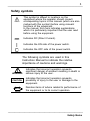
Safety symbols
This symbol is affixed to locations on the
equipment where the operator should consult
corresponding topics in this manual (which are also
marked with this symbol) before using relevant
functions of the equipment.
In the manual, this mark indicates explanations
which it is particularly important that the user read
before using the equipment.
Indicates DC (Direct Current).
Indicates the ON side of the power switch.
Indicates the OFF side of the power switch.
The following symbols are used in this
Instruction Manual to indicate the relative
importance of cautions and warnings.
WARNING
CAUTION
NOTE
Indicates that incorrect operation presents
significant danger of accident resulting in death or
serious injury to the user.
Indicates that incorrect operation presents
possibility of injury to the user or damage to the
equipment.
Denotes items of advice related to performance of
the equipment or to its correct operation.
_____________________________________________
Safety Notes
4
__________________________________________________
Accuracy
The specifications in this manual include figures
for "measurement accuracy" when referring to
digital measuring instruments, and for
"measurement tolerance" when referring to
analog instruments.
f.s.
(maximum display or scale value, or length of
scale)
Signifies the maximum display (scale) value or the
length of the scale (in cases where the scale
consists of unequal increments or where the
maximum value cannot be defined).
In general, this is the range value (the value
written on the range selector or equivalent)
currently in use.
rdg.
(displayed or indicated value)
This signifies the value actually being measured,
i.e., the value that is currently indicated or
displayed by the measuring instrument.
dgt.
(resolution)
Signifies the smallest display unit on a digital
measuring instrument, i.e., the value displayed
when the last digit on the digital display is "1".
_____________________________________________
Safety Notes
5
__________________________________________________
Notes on Use
CAUTION
The detector and display of this unit can be
separated. In order to prevent damage to this unit,
always power off before separating or putting
together.
To avoid damage to the unit, do not short the
ANALOG OUT terminal and do not input voltage to
the ANALOG OUT terminal.
This product is not designed to be entirely water- or
dust-proof. To avoid damage, do not use it in a wet
or dusty environment.
Do not store or use the product where it could be
exposed to high temperature or humidity, or
condensation. Under such conditions, the product
may be damaged and insulation may deteriorate so
that it no longer meets specifications.
Do not use the product where it may be exposed to
corrosive or combustible gases. The product may
be damaged.
To avoid damage to the product, protect it from
vibration or shock during transport and handling,
and be especially careful to avoid dropping.
_____________________________________________
Notes on Use
6
__________________________________________________
NOTE
When taking measurements from ordinary
lighting fixtures, the display will sometimes
"roll", and be hard to read. This is generally
due to fluctuations in the line voltage to the
fixture or shadows caused by people in the
area etc. Please note this in measuring.
This instrument is equipped with a backlight in
the display for measuring under the low
illuminance. The brightness is set lowest, for
the low consumption of the batteries. It also
goes out automatically in approx. eight
seconds, after it is turned on, in order to
prevent the effect of backlight on the
illuminance.
The reference level as marked on the faceplate
is the tip of the light sensor.
The
indicator appears when battery voltage
becomes low. Replace the batteries as soon
as possible.
Do not take this instrument apart or subject it
to any shock or impact.
_____________________________________________
Notes on Use
7
__________________________________________________
Chapter 1
Overview
1.1 Product Overview
The 3423 is suited for a wide range of
applications involving illumination equipment,
lighting work and facility management.
The instrument has five measurement ranges,
20 lx to 200,000 lx, so it can measure the wide
range of illuminance.
It can measure, with the detector separated
from the display and has a large LCD easy to
read in the display, for user's convenience.
Moreover, the backlight allows to take readings
easily under the low illuminance. (The display is
held when the backlight turns on and the
backlighting has no effect on the measurement. )
By using the silicon diode and optical filter in
the detector, the visual perception is corrected
so that the perception of colors is close to
human perception. The instrument has a
microcomputer and can perform the auto range,
one-touch zero adjustment of analog output. An
AC adapter is also available, as well as
batteries, and useful for long-time
measurement.
_____________________________________________
Notes on Use
8
__________________________________________________
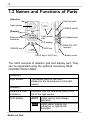
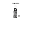
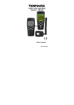
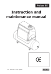
1.2 Names and Functions of Parts
[Detector]
Ejection hook
Light sensor
POWER switch
[Display]
Light sensor
cap
Reference level
indication
AC adapter jack
LCD display
RANGE key
0 ADJ key
HOLD key/ LIGHT key
ANALOG OUT
terminal
Battery cover
The 3423 consists of detector part and display part. They
can be separated using the optional accessory 9436
CONNECTION CABLE.
[Detector]
Light sensor
The sensor part for the 3423
Measures the illuminance on the light
sensor.
[Display]
Reference level
indication
Indicates that the reference level is the
tip of the light sensor.
LCD display
AUTO
Lights during Auto Range
operation.
HOLD
Lights when holding the
indication or lighting the
backlight.
_____________________________________________
Notes on Use
9
__________________________________________________
LCD display
Lights when battery power is
running low.
0
Lights when measuring in the
20,000 lx range.
00
Lights when measuring in the
200,000 lx range.
lx
Indicates the unit of illuminance
(lux).
.
Indicates the decimal point.
RANGE key
Selects the range.
HOLD key,
LIGHT key
Holds the indication or lights the
backlight.
0 ADJ key
Performs zero adjustment.
Light sensor cap
Attached to the detector, when
performing zero adjustment.
Ejection hook
Used to separate and put together the
detector and display.
POWER switch
Powers on and off.
AC adapter jack
Input jack for an AC adapter.
ANALOG OUT
terminal
Performs analog output of illuminance.
(The optional accessory, 9094 OUTPUT
CORD is used. )
Battery cover
Removed when changing batteries.
_____________________________________________
Notes on Use
10
__________________________________________________
_____________________________________________
Notes on Use
11
__________________________________________________
Chapter 2
Preparing for
measurement
2.1 Installing or Replacing the
Batteries
WARNING
To avoid electrocution, turn off the power
switch and disconnect the AC adapter cord
before removing the lithium battery.
After replacing the batteries, replace the cover
and screws before using the product.
Do not mix old and new batteries, or different
types of batteries. Also, be careful to observe
battery polarity during installation. Otherwise,
poor performance or damage from battery
leakage could result.
To avoid the possibility of explosion, do not
short circuit, disassemble or incinerate
batteries.
Handle and dispose of batteries in accordance
with local regulations.
_____________________________________________
Notes on Use
12
__________________________________________________
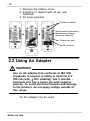
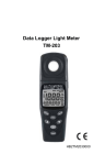
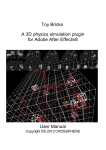
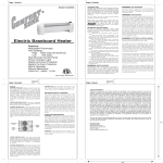
1. Remove the battery cover.
2. Installing or replace with all two new
batteries.
3. Fit cover properly
Collation number
Measurement procedure
Measurement range,
Notes on batteries
Production year
Serial number
2.2 Using An Adapter
WARNING
Use an AC adapter that conforms to IEC 950
standards in respect to safety is rated for 6 V 300 mA (with 10% stability), has 5 mm-dia. terminals and has a center pin with negative
polarity. To avoid electrical hazards and damage
to the product, do not apply voltage outside of
this range.
An AC adapter can be used.
_____________________________________________
Notes on Use
13
__________________________________________________
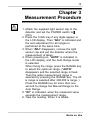
Chapter 3
Measurement Procedure
1. Attach the supplied light sensor cap to the
detector and set the POWER switch to
(ON).
2. Press the 0 ADJ key if any digits appear in
the LCD display. Then "ADJ" is indicated and
the zero adjustment for all ranges is
performed at the same time.
3. When "ADJ" disappears, remove the light
sensor cap and put the detector where the
measurement is taken.
4. When powering on, "AUTO" is indicated in
the LCD display, and the Auto Range mode
is selected.
When fixing the range, press the RANGE key
to select the optimum range. ("AUTO"
disappears and the selected range is fixed.
Then the wider measurement range is
selected by pressing the RANGE key. The 20
lx range is selected after 200,000 lx range. )
Press the RANGE key for more than one
second to change the Manual Range to the
Auto Range.
5. "OF" is indicated, when the measured value
exceeds the measurement range.
6. Take the reading, When it is stable.
_____________________________________________
Notes on Use
14
__________________________________________________
7. Press the HOLD key to hold the reading.
Press it again to release holding. (The
analog output is not held. The range
switching and zero adjustment is impossible,
when holding. )
8. Press the LIGHT key for more than one
second to turn on the backlight. The reading
is held automatically, when it lights.
The backlight lights for approx. eight
seconds, and then goes out automatically.
(Holding is not released after the backlight
goes out. If you press the LIGHT key again
within eight seconds, the backlight goes out
and holding is released. )
9. When using the analog output, connect the
ANALOG OUT terminal and the recorder etc.
with the 9094 OUTPUT CORD (option).
The analog output value varies by 0.1 mV as
the display value varies by 1 digit.
When the illuminance varies, if the Auto
Range is selected, the range may change
and the full scale value may vary. In this
case, use in the Manual Range.
10. When battery power is running low, the
indication lights. Please change the batteries.
11. When measuring with the detector separated
form the display, pull the detector slowly,
holding the display and pressing both ejection
hooks, after making sure that the POWER
switch is
(OFF). Use the 9436
CONNECTION CABLE (with case) (option) to
connect the detector and the display.
12. After finishing measurement, attach the light
sensor cap and set the POWER switch to
(OFF).
_____________________________________________
Notes on Use
15
__________________________________________________
NOTE
When the light sensor cap is not attached
(more than approx. 1 lx is indicated), "CAP" is
indicated. Make sure that it is attached.
If performing the zero adjustment soon after
powering on, several digits may not disappear.
In this case, perform the zero adjustment
again.
Do not connect or disconnect the AC adapter,
and the detector and the display, with the
POWER switch on.
Setting the POWER switch to (ON) soon after
setting to
(OFF) may cause malfunction. In
this case, power on in several seconds after
setting to
(OFF).
Use the backlight under low illiminance. It may
be difficult to find it under ordinary illuminance.
as the brightness is set lowest for the low
consumption of batteries.
_____________________________________________
Notes on Use
16
__________________________________________________
_____________________________________________
Notes on Use
17
__________________________________________________
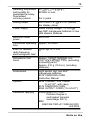
Chapter 4
General Specifications
Class
Conforms to JIS C 1609-1993
general AA class
Type
Weights and Measure Act, type
approval E-11
Display
LCD 3 1/2 Maximum "1999"
However, in the 20,000 lx range, the
maximum is "19,990" and in the
"200,000 lx range, the maximum is
"199,900"
Auto (AUTO) display indicator
HOLD ( HOLD ) display indicator
Battery consumption ( ) display
indicator
Unit symbol (lx) display indicator
EL backlight function
Display operation
20, 200, 2,000 lx range: 1-count step
20,000 lx range: 10-count steps
200,000 lx range: 100-count steps
Measuring ranges
20/200/2,000/20,000/200,000 lx
Auto/manual switching
Overflow indication
"OF" is displayed
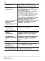
Accuracy
Angled incident light
characteristics
4%rdg.
1 dgt. (23 5 /73 41
)
Angle Deviation from cosine
characteristics
10
1%
30
2%
50
6%
60
7%
80
25%
_____________________________________________
Notes on Use
18
__________________________________________________
Response time
Auto range: 5 seconds or less
Manual range: 2 seconds or less
Temperature
characteristics
Deviation from value measured at 23
(73 ) between -10 (50 ) and
40 (104 ): 3%
Humidity characteristics: Deviation
from value measured in an
environment with a temperature and
humidity of 23 (73 ) and 45% to
75% rh when the unit is left in an
85% to 95% rh environment for three
hours and then is returned to the
original environment : 3%
Relative spectral
response
characteristics in the
visible spectrum
Deviation from spectral luminous
efficiency: 8% or less
Response
characteristics in
ultraviolet and
infrared spectrums
Response to ultraviolet and infrared
radiation: less than 1%
Fatique
characteristics
Change in value one minute and ten
minutes after light strikes sensor :
1%
Characteristics
regarding intermittent
light
Deviation in value when subjected to
intermittent light for 1/2 cycle at a
frequency of 100 Hz or 120 Hz:
2%
Receptor element
Silicon photodiode
Operating
temperature and
humidity range
-10 to 40 (50 to 104 ), 80% RH
or less (no condensation)
Storage temperature
and humidity range
-10 to 50 (50 to 122 ), 80% RH
or less (no condensation)
_____________________________________________
Notes on Use
19
__________________________________________________
Operating temperature
and humidity for
guaranteed accuracy
Guaranteed
accuracy period
23
5 (73
80%RH or less
Analog output
200 mVDC f.s. 2.5% f.s. (versus
the display value)
Power supply
Rated supply voltage 1.5 VDC 2
two R6P manganese batteries or two
LR6 alkaline batteries
Maximum rated
power
600 mVA
Continuous operating
time
Approx. 25 hours
Effect of radiated
radio-frequency
electromagnetic field
9
),
For 2 years
120 dgt. at 3 V/m
Dimensions and
mass
Approx. 74W 170H 30D mm
(2.91"W 6.69"H 1.19"D) (excluding
protruding parts)
Approx. 310 g (10.9 oz.) (including
batteries)
Accessories
Light sensor cap, two R6P
manganese batteries
9376 CARRYING CASE
Instruction Manual
Options
9436 CONNECTION CABLE
(2 m/7.87", with case)
9376 CARRYING CASE,
9094 OUTPUT CORD (1.5 m/5.91")
Standards Applying
Safety EN61010-1:2001
Pollution Degree 2,
(anticipated transient
overvoltage 330 V)
EMC
EN61326:1997+A1:1998+A2:2001
+A3:2003
_____________________________________________
Notes on Use
20
__________________________________________________
_____________________________________________
Notes on Use
21
__________________________________________________
Chapter 5
Using this unit for legal
purpose
This unit is approved under Weights and
Measures legislation by the Japanese Ministry
of Economy, Trade and Industry. An official
approval from the Japan Electric Meters
Inspection Corporation is necessary for this unit
to be used as an illuminance meter for legal
purposes. After the approval, the unit can be
used for trade and evidential purposes. The
approval can be issued by HIOKI. After the
approval, a seal is affixed, and the unit can be
used as a legally certified illuminance meter for
two years. When the approval expires,
recalibration and a new official approval are
required.
_____________________________________________
Notes on Use
22
__________________________________________________
_____________________________________________
Notes on Use
23
__________________________________________________
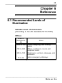
Chapter 6
Reference
6.1 Recommended Levels of
Illumination
Suitable levels of illuminance
(According to the JIS standard Z 9110-1979)
Offices
Level of
illuminance
(lx)
Place
1500 to 750
Offices, designing, and drawing
rooms
750 to 300
Offices, conference rooms, and
computer rooms
300 to 100
Workrooms, corridors, stairways, and
restrooms
75 to 30
Indoor emergency stairways
_____________________________________________
Notes on Use
24
__________________________________________________
Factories
Level of
illuminance
(lx)
Place
3000 to 1500 Where such work as assembling,
inspecting, testing, selecting and
extremely precision visual work
1500 to 750
Assembling, inspecting, testing,
selecting and precision visual work
750 to 300
Assembling, inspecting, testing,
selecting and visual ordinary work
300 to 150
Wrapping and packing
75 to 30
Indoor emergency stairways
Schools
Level of
illuminance
(lx)
Place
1500 to 300
Precision drawing or drafting,
precision experimenting, library
reading rooms and precision
handicraft
750 to 200
Classrooms, library reading rooms,
experiment demonstration rooms,
staff rooms and gymnasia
300 to 75
Lecture halls, assembly rooms,
locker rooms, corridors, stairways
and restrooms
75 to 30
Warehouses and emergency
stairways
10 to 2
School passages (for night)
_____________________________________________
Notes on Use
25
__________________________________________________
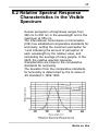
6.2 Relative Spectral Response
Characteristics in the Visible
Spectrum
Relative luminous
Human perception of brightness ranges from
360 nm to 830 nm in the wavelength and is the
maximum at 555 nm.
The International Commission on Illumination
(CIE) has established comparative standards for
luminosity, setting the maximum perception for
1 and indicating the amount of perception of
each wavelength by the relative value, and
calculating the average of many people. In the
3423, the relative spectral response
characteristics are close to the comparative
standards for luminosity.
The deviation from the comparative standards
for luminosity is determined by the fs value of
JIS standard C 1609-1993.
_____________________________________________
Notes on Use
26
__________________________________________________
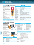
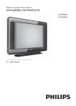
6.3 Angled Incident Light
Characteristics
Deviation from consine
characteristics (%)
It is known that the luminance is proportional to
the cosine of the incident angle of light (the
cosine law).
In the 3423, the shape of the light sensor, hook
etc. is so made that it can follow the cosine law
closely.
_____________________________________________
Notes on Use
27
__________________________________________________
Chapter 7
Maintenance and Service
7.1 Message
OF
Indicates the measured value exceeds
the measurement range.
ADJ Indicates the zero adjustment is being
performed.
CAP Indicates that the light sensor cap must
be attached to the detector, during the
zero adjustment.
7.2 Cleaning
To clean the product, wipe it gently with a soft
cloth moistened with water or mild detergent.
Never use solvents such as benzene, alcohol,
acetone, ether, ketones, thinners or gasoline, as
they can deform and discolor the case.
Wipe dirt from the detector with a dry cloth etc.,
when it is dirty.
_____________________________________________
Notes on Use
28
__________________________________________________
7.3 Calibration and Repair
The calibration interval for the 3423 is two
years. It is recommended to calibrate it every
two years, for accurate measurement. Contact
your nearest service representative.
If the unit is not functioning properly, check the
batteries. If a problem is found, contact your
dealer or HIOKI representative.
Pack the unit carefully so that it will not be
damaged during transport, and write a detailed
description of the problem. HIOKI cannot bear
any responsibility for damage that occurs during
shipment.
_____________________________________________
Notes on Use
HIOKI 3423 LUX HiTESTER
Instruction Manual
Publication date:
September 2006
Revised edition 8
Edited and published by HIOKI E.E. CORPORATION
Technical Sales Support Section
All inquiries to Sales and Marketing International
Department
81 Koizumi, Ueda, Nagano, 386-1192, Japan
TEL: +81-268-28-0562 / FAX: +81-268-28-0568
E-mail: [email protected]
URL http://www.hioki.co.jp/
Printed in Japan 3423A980-08
・ All reasonable care has been taken in the production of this
manual, but if you find any points which are unclear or in
error, please contact your supplier or the Sales and
Marketing International Department at HIOKI headquarters.
・ In the interests of product development, the contents of this
manual are subject to revision without prior notice.
・ Unauthorized reproduction or copying of this manual is
prohibited.
HEAD OFFICE
81 Koizumi, Ueda, Nagano 386-1192, Japan
TEL +81-268-28-0562 / FAX +81-268-28-0568
E-mail: [email protected]
URL http: //www.hioki.co.jp/
HIOKI USA CORPORATION
6 Corporate Drive, Cranbury, NJ 08512, USA
TEL +1-609-409-9109 / FAX +1-609-409-9108
Printed on recycled paper