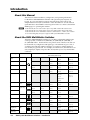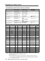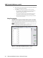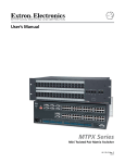
1
SMX System MultiMatrix Switcher 68-1452-01 Rev. A 10 09 Precautions Safety Instructions • English Warning This symbol is intended to alert the user of important operating and maintenance (servicing) instructions in the literature provided with the equipment. Power sources • This equipment should be operated only from the power source indicated on the product. This equipment is intended to be used with a main power system with a grounded (neutral) conductor. The third (grounding) pin is a safety feature, do not attempt to bypass or disable it. This symbol is intended to alert the user of the presence of uninsulated dangerous voltage within the product’s enclosure that may present a risk of electric shock. Power disconnection • To remove power from the equipment safely, remove all power cords from the rear of the equipment, or the desktop power module (if detachable), or from the power source receptacle (wall plug). Caution Read Instructions • Read and understand all safety and operating instructions before using the equipment. Retain Instructions • The safety instructions should be kept for future reference. Follow Warnings • Follow all warnings and instructions marked on the equipment or in the user information. Avoid Attachments • Do not use tools or attachments that are not recommended by the equipment manufacturer because they may be hazardous. Consignes de Sécurité • Français Power cord protection • Power cords should be routed so that they are not likely to be stepped on or pinched by items placed upon or against them. Servicing • Refer all servicing to qualified service personnel. There are no user-serviceable parts inside. To prevent the risk of shock, do not attempt to service this equipment yourself because opening or removing covers may expose you to dangerous voltage or other hazards. Slots and openings • If the equipment has slots or holes in the enclosure, these are provided to prevent overheating of sensitive components inside. These openings must never be blocked by other objects. Lithium battery • There is a danger of explosion if battery is incorrectly replaced. Replace it only with the same or equivalent type recommended by the manufacturer. Dispose of used batteries according to the manufacturer’s instructions. Avertissement Ce symbole sert à avertir l’utilisateur que la documentation fournie avec le matériel contient des instructions importantes concernant l’exploitation et la maintenance (réparation). Alimentations• Ne faire fonctionner ce matériel qu’avec la source d’alimentation indiquée sur l’appareil. Ce matériel doit être utilisé avec une alimentation principale comportant un fil de terre (neutre). Le troisième contact (de mise à la terre) constitue un dispositif de sécurité : n’essayez pas de la contourner ni de la désactiver. Ce symbole sert à avertir l’utilisateur de la présence dans le boîtier de l’appareil de tensions dangereuses non isolées posant des risques d’électrocution. Déconnexion de l’alimentation• Pour mettre le matériel hors tension sans danger, déconnectez tous les cordons d’alimentation de l’arrière de l’appareil ou du module d’alimentation de bureau (s’il est amovible) ou encore de la prise secteur. Attention Lire les instructions• Prendre connaissance de toutes les consignes de sécurité et d’exploitation avant d’utiliser le matériel. Conserver les instructions• Ranger les consignes de sécurité afin de pouvoir les consulter à l’avenir. Respecter les avertissements • Observer tous les avertissements et consignes marqués sur le matériel ou présentés dans la documentation utilisateur. Eviter les pièces de fixation • Ne pas utiliser de pièces de fixation ni d’outils non recommandés par le fabricant du matériel car cela risquerait de poser certains dangers. Protection du cordon d’alimentation • Acheminer les cordons d’alimentation de manière à ce que personne ne risque de marcher dessus et à ce qu’ils ne soient pas écrasés ou pincés par des objets. Réparation-maintenance • Faire exécuter toutes les interventions de réparation-maintenance par un technicien qualifié. Aucun des éléments internes ne peut être réparé par l’utilisateur. Afin d’éviter tout danger d’électrocution, l’utilisateur ne doit pas essayer de procéder lui-même à ces opérations car l’ouverture ou le retrait des couvercles risquent de l’exposer à de hautes tensions et autres dangers. Fentes et orifices • Si le boîtier de l’appareil comporte des fentes ou des orifices, ceux-ci servent à empêcher les composants internes sensibles de surchauffer. Ces ouvertures ne doivent jamais être bloquées par des objets. Lithium Batterie • Il a danger d’explosion s’ll y a remplacment incorrect de la batterie. Remplacer uniquement avec une batterie du meme type ou d’un ype equivalent recommande par le constructeur. Mettre au reut les batteries usagees conformement aux instructions du fabricant. Sicherheitsanleitungen • Deutsch Vorsicht Dieses Symbol soll dem Benutzer in der im Lieferumfang enthaltenen Dokumentation besonders wichtige Hinweise zur Bedienung und Wartung (Instandhaltung) geben. Stromquellen • Dieses Gerät sollte nur über die auf dem Produkt angegebene Stromquelle betrieben werden. Dieses Gerät wurde für eine Verwendung mit einer Hauptstromleitung mit einem geerdeten (neutralen) Leiter konzipiert. Der dritte Kontakt ist für einen Erdanschluß, und stellt eine Sicherheitsfunktion dar. Diese sollte nicht umgangen oder außer Betrieb gesetzt werden. Dieses Symbol soll den Benutzer darauf aufmerksam machen, daß im Inneren des Gehäuses dieses Produktes gefährliche Spannungen, die nicht isoliert sind und die einen elektrischen Schock verursachen können, herrschen. Stromunterbrechung • Um das Gerät auf sichere Weise vom Netz zu trennen, sollten Sie alle Netzkabel aus der Rückseite des Gerätes, aus der externen Stomversorgung (falls dies möglich ist) oder aus der Wandsteckdose ziehen. Achtung Lesen der Anleitungen • Bevor Sie das Gerät zum ersten Mal verwenden, sollten Sie alle Sicherheits-und Bedienungsanleitungen genau durchlesen und verstehen. Aufbewahren der Anleitungen • Die Hinweise zur elektrischen Sicherheit des Produktes sollten Sie aufbewahren, damit Sie im Bedarfsfall darauf zurückgreifen können. Befolgen der Warnhinweise • Befolgen Sie alle Warnhinweise und Anleitungen auf dem Gerät oder in der Benutzerdokumentation. Keine Zusatzgeräte • Verwenden Sie keine Werkzeuge oder Zusatzgeräte, die nicht ausdrücklich vom Hersteller empfohlen wurden, da diese eine Gefahrenquelle darstellen können. Instrucciones de seguridad • Español Schutz des Netzkabels • Netzkabel sollten stets so verlegt werden, daß sie nicht im Weg liegen und niemand darauf treten kann oder Objekte darauf- oder unmittelbar dagegengestellt werden können. Wartung • Alle Wartungsmaßnahmen sollten nur von qualifiziertem Servicepersonal durchgeführt werden. Die internen Komponenten des Gerätes sind wartungsfrei. Zur Vermeidung eines elektrischen Schocks versuchen Sie in keinem Fall, dieses Gerät selbst öffnen, da beim Entfernen der Abdeckungen die Gefahr eines elektrischen Schlags und/oder andere Gefahren bestehen. Schlitze und Öffnungen • Wenn das Gerät Schlitze oder Löcher im Gehäuse aufweist, dienen diese zur Vermeidung einer Überhitzung der empfindlichen Teile im Inneren. Diese Öffnungen dürfen niemals von anderen Objekten blockiert werden. Litium-Batterie • Explosionsgefahr, falls die Batterie nicht richtig ersetzt wird. Ersetzen Sie verbrauchte Batterien nur durch den gleichen oder einen vergleichbaren Batterietyp, der auch vom Hersteller empfohlen wird. Entsorgen Sie verbrauchte Batterien bitte gemäß den Herstelleranweisungen. Advertencia Este símbolo se utiliza para advertir al usuario sobre instrucciones importantes de operación y mantenimiento (o cambio de partes) que se desean destacar en el contenido de la documentación suministrada con los equipos. Alimentación eléctrica • Este equipo debe conectarse únicamente a la fuente/tipo de alimentación eléctrica indicada en el mismo. La alimentación eléctrica de este equipo debe provenir de un sistema de distribución general con conductor neutro a tierra. La tercera pata (puesta a tierra) es una medida de seguridad, no puentearia ni eliminaria. Este símbolo se utiliza para advertir al usuario sobre la presencia de elementos con voltaje peligroso sin protección aislante, que puedan encontrarse dentro de la caja o alojamiento del producto, y que puedan representar riesgo de electrocución. Desconexión de alimentación eléctrica • Para desconectar con seguridad la acometida de alimentación eléctrica al equipo, desenchufar todos los cables de alimentación en el panel trasero del equipo, o desenchufar el módulo de alimentación (si fuera independiente), o desenchufar el cable del receptáculo de la pared. Precaucion Leer las instrucciones • Leer y analizar todas las instrucciones de operación y seguridad, antes de usar el equipo. Conservar las instrucciones • Conservar las instrucciones de seguridad para futura consulta. Obedecer las advertencias • Todas las advertencias e instrucciones marcadas en el equipo o en la documentación del usuario, deben ser obedecidas. Evitar el uso de accesorios • No usar herramientas o accesorios que no sean especificamente recomendados por el fabricante, ya que podrian implicar riesgos. 安全须知 • 中文 这个符号提示用户该设备用户手册中有重要的操作和维护说明。 这个符号警告用户该设备机壳内有暴露的危险电压,有触电危险。 注意 阅读说明书 • 用户使用该设备前必须阅读并理解所有安全和使用说明。 保存说明书 • 用户应保存安全说明书以备将来使用。 遵守警告 • 用户应遵守产品和用户指南上的所有安全和操作说明。 避免追加 • 不要使用该产品厂商没有推荐的工具或追加设备,以避免危险。 Protección del cables de alimentación • Los cables de alimentación eléctrica se deben instalar en lugares donde no sean pisados ni apretados por objetos que se puedan apoyar sobre ellos. Reparaciones/mantenimiento • Solicitar siempre los servicios técnicos de personal calificado. En el interior no hay partes a las que el usuario deba acceder. Para evitar riesgo de electrocución, no intentar personalmente la reparación/mantenimiento de este equipo, ya que al abrir o extraer las tapas puede quedar expuesto a voltajes peligrosos u otros riesgos. Ranuras y aberturas • Si el equipo posee ranuras o orificios en su caja/alojamiento, es para evitar el sobrecalientamiento de componentes internos sensibles. Estas aberturas nunca se deben obstruir con otros objetos. Batería de litio • Existe riesgo de explosión si esta batería se coloca en la posición incorrecta. Cambiar esta batería únicamente con el mismo tipo (o su equivalente) recomendado por el fabricante. Desachar las baterías usadas siguiendo las instrucciones del fabricante. 警告 电源 • 该设备只能使用产品上标明的电源。 设备必须使用有地线的供电系统供电。 第三条线 (地线)是安全设施,不能不用或跳过 。 拔掉电源 • 为安全地从设备拔掉电源,请拔掉所有设备后或桌面电源的电源线,或任何接到市 电系统的电源线。 电源线保护 • 妥善布线, 避免被踩踏,或重物挤压。 维护 • 所有维修必须由认证的维修人员进行。 设备内部没有用户可以更换的零件。为避免出现 触电危险不要自己试图打开设备盖子维修该设备。 通风孔 • 有些设备机壳上有通风槽或孔,它们是用来防止机内敏感元件过热。 不要用任何东 西挡住通风孔。 锂电池 • 不正确的更换电池会有爆炸的危险。必须使用与厂家推荐的相同或相近型号的电池。 按照生产厂的建议处理废弃电池。 FCC Class A Notice This equipment has been tested and found to comply with the limits for a Class A digital device, pursuant to part 15 of the FCC Rules. Operation is subject to the following two conditions: (1) this device may not cause harmful interference, and (2) this device must accept any interference received, including interference that may cause undesired operation. The Class A limits are designed to provide reasonable protection against harmful interference when the equipment is operated in a commercial environment. This equipment generates, uses, and can radiate radio frequency energy and, if not installed and used in accordance with the instruction manual, may cause harmful interference to radio communications. Operation of this equipment in a residential area is likely to cause harmful interference, in which case the user will be required to correct the interference at his own expense. N This unit was tested with shielded cables on the peripheral devices. Shielded cables must be used with the unit to ensure compliance with FCC emissions limits. 声明 所使用电源为 A 级产品,在生活环境中,该产品可能会造成无线电干扰。在这种情况下,可能需要用户对其干扰采 取切实可行的措施。 Table of Contents Chapter One • Introduction . ..................................................................................................... 1-1 About this Manual..................................................................................................................... 1-2 About the SMX MultiMatrix Switcher........................................................................... 1-2 Definitions. ................................................................................................................................. 1-4 Features....................................................................................................................................... 1-5 Chapter Two • Installation ............................................................................................................ 2 UL/Safety Requirements......................................................................................................... 2-2 Important safety instructions................................................................................................... 2-2 Mounting the Switcher........................................................................................................... 2-3 Installing new boards into an empty SMX frame............................................................... 2-4 Replacing an existing I/O board.......................................................................................... 2-4 Rear Panel Features and Connections............................................................................ 2-5 Power and control connections............................................................................................... 2-5 Choosing a network cable................................................................................................... 2-5 Ethernet cable termination............................................................................................ 2-6 Input/output boards.................................................................................................................. 2-6 Wiring the audio connectors. .................................................................................................. 2-8 Chapter Three • Operation and Setup............................................................................... 3-1 Front Panel Features................................................................................................................. 3-2 I/O plane selection buttons...................................................................................................... 3-2 Input and output buttons. ....................................................................................................... 3-2 Control buttons.......................................................................................................................... 3-3 Power indicator LED’s. .............................................................................................................. 3-4 Front panel configuration port............................................................................................... 3-4 Powering up . ................................................................................................................................ 3-4 Front Panel Operation. ............................................................................................................ 3-5 Ties — General information..................................................................................................... 3-5 Creating ties. .............................................................................................................................. 3-5 Viewing ties................................................................................................................................ 3-6 An example of viewing a set of video or audio ties.......................................................... 3-6 Removing ties............................................................................................................................. 3-7 An example of removing ties from an existing set of video or audio ties........................ 3-7 Replacing ties............................................................................................................................. 3-8 An example of replacing an existing tied input with another input................................ 3-8 Muting or unmuting a video, audio, or video and audio output...................................... 3-9 Muting an output................................................................................................................. 3-9 Unmuting an output.......................................................................................................... 3-10 I/O Presets. ................................................................................................................................ 3-10 Saving or recalling a Global Preset. ...................................................................................... 3-11 SMX System MultiMatrix Switchers • Table of Contents i PRELIMINARY Tabletop placement................................................................................................................... 2-3 UL guidelines for rack mounted devices ............................................................................... 2-3 Rack mounting........................................................................................................................... 2-3 Installing the input/output boards.......................................................................................... 2-4 Table of Contents, cont’d Saving or recalling a Plane Preset......................................................................................... 3-11 Setting RGB Delay (VGA and RGBHV boards only)............................................................. 3-12 Setting the front panel locks (Executive modes). ............................................................... 3-13 Selecting Lock mode 2 or toggling between mode 2 and mode 0................................. 3-13 Selecting Lock mode 1 or toggling between mode 2 and mode 1................................. 3-13 Background illumination settings......................................................................................... 3-14 Rear Panel RS-232/RS-422 Communications............................................................. 3-14 Configuration using the front panel.................................................................................... 3-14 Viewing and Adjusting the Audio Input Level....................................................... 3-14 Using the front panel.............................................................................................................. 3-14 Viewing and Adjusting the Audio Output Volume. ............................................ 3-16 Using the front panel.............................................................................................................. 3-16 Reset Levels.................................................................................................................................. 3-18 Reset mode uses....................................................................................................................... 3-18 PRELIMINARY Chapter Four • Programmer’s Guide................................................................................... 4-1 RS-232/RS-422 Link. .................................................................................................................... 4-2 Ethernet (LAN) Port................................................................................................................... 4-2 Ethernet connection.................................................................................................................. 4-2 Default IP addresses.................................................................................................................. 4-2 Establishing a connection......................................................................................................... 4-2 Connection Timeouts. ............................................................................................................... 4-3 Number of connections. ........................................................................................................... 4-3 Using Verbose Mode................................................................................................................. 4-3 Host-to-Switcher Instructions............................................................................................. 4-3 Switcher-Initiated Messages................................................................................................ 4-3 Switcher Error Responses...................................................................................................... 4-4 Using the Command/Response Table for SIS Commands................................... 4-5 Symbol definitions..................................................................................................................... 4-5 Command/response table for SIS commands (continued)................................................... 4-9 Command/response table for SIS commands (continued)................................................. 4-10 Command/response table for SIS commands (continued)................................................. 4-11 Command/response table for SIS commands (continued)................................................. 4-12 Command/response table for SIS commands (continued)................................................. 4-13 Command/response table for SIS commands (continued)................................................. 4-14 Command/response table for SIS commands (continued)................................................. 4-15 Command/response table for SIS commands (continued)................................................. 4-16 Command/response table for SIS commands (continued)................................................. 4-17 Using the Command/Response Table for IP SIS Commands........................... 4-18 Symbol Definitions:. ................................................................................................................ 4-18 Command/response table for IP SIS commands.................................................................. 4-20 Command/response table for IP SIS commands (continued)............................................. 4-21 ii SMX System MultiMatrix Switchers • Table of Contents Chapter Five • SMX Control Software............................................................................... 5-1 Installing and Starting the SMX Control Program................................................. 5-2 Installing the program.............................................................................................................. 5-2 Starting the program................................................................................................................ 5-3 Using the program..................................................................................................................... 5-4 File......................................................................................................................................... 5-5 Tools...................................................................................................................................... 5-6 Audio-input-Config............................................................................................................ 5-12 Preferences......................................................................................................................... 5-13 Master-Reset....................................................................................................................... 5-14 Help..................................................................................................................................... 5-15 Customizing the SMX window. ............................................................................................. 5-16 Managing ties. ......................................................................................................................... 5-17 To create a tie..................................................................................................................... 5-17 To remove a tie .................................................................................................................. 5-17 To view information on a input or output....................................................................... 5-18 IP settings/options. .................................................................................................................. 5-18 Setting the IP address......................................................................................................... 5-19 Setting the Extron name or descriptor............................................................................. 5-19 Setting the gateway IP address......................................................................................... 5-20 Setting the subnet mask.................................................................................................... 5-20 Hardware address field...................................................................................................... 5-20 Enabling/disabling DHCP................................................................................................... 5-20 Setting the date.................................................................................................................. 5-21 Setting the local time......................................................................................................... 5-21 Sync Time to PC button...................................................................................................... 5-21 Setting the offset from GMT............................................................................................. 5-21 Enabling daylight savings time.......................................................................................... 5-21 Setting the administrator password.................................................................................. 5-21 Setting the user password................................................................................................. 5-22 Setting the mail server IP address..................................................................................... 5-22 Setting the mail server domain name............................................................................... 5-23 Entering e-mail addressee information............................................................................ 5-23 Updating the firmware........................................................................................................... 5-24 Uploading HTML files. ............................................................................................................ 5-26 Windows buttons, menus, and trash can............................................................................. 5-27 Special Characters.................................................................................................................... 5-27 SMX System MultiMatrix Switchers • Table of Contents iii PRELIMINARY Control program menus and pages........................................................................................ 5-5 Table of Contents, cont’d Chapter Six • HTML Operation................................................................................................. 6-1 Accessing the Web Pages....................................................................................................... 6-2 System Status Pages................................................................................................................. 6-3 System Status.............................................................................................................................. 6-3 Physical Configuration.............................................................................................................. 6-4 DSVP . .......................................................................................................................................... 6-4 Configuration Pages................................................................................................................. 6-5 System Settings page. ............................................................................................................... 6-5 PRELIMINARY IP Settings fields................................................................................................................... 6-5 Unit Name field............................................................................................................... 6-5 DHCP radio buttons........................................................................................................ 6-6 IP Address field............................................................................................................... 6-6 Gateway IP Address field................................................................................................ 6-6 Subnet Mask field........................................................................................................... 6-6 MAC Address field.......................................................................................................... 6-6 Firmware field................................................................................................................. 6-6 Model field...................................................................................................................... 6-6 Part Number field........................................................................................................... 6-6 Date/Time Settings fields..................................................................................................... 6-7 Passwords page.......................................................................................................................... 6-8 Email Settings page................................................................................................................... 6-9 Mail IP Address field............................................................................................................. 6-9 Domain Name field.............................................................................................................. 6-9 SMTP Authorization Required field.................................................................................... 6-9 Email Address fields........................................................................................................... 6-10 Firmware Upgrade page......................................................................................................... 6-11 File Management Page.......................................................................................................... 6-12 Uploading files......................................................................................................................... 6-13 Adding a directory................................................................................................................... 6-13 Other file management activities. ........................................................................................ 6-13 Control Pages.............................................................................................................................. 6-14 User Control page.................................................................................................................... 6-14 To set or replace ties........................................................................................................... 6-14 To remove ties..................................................................................................................... 6-15 To set input audio levels.................................................................................................... 6-15 To set output volume levels............................................................................................... 6-16 To mute or unmute a signal............................................................................................... 6-17 EDID configuration............................................................................................................. 6-18 Presets page.............................................................................................................................. 6-19 Saving the current configuration as a global preset........................................................ 6-19 Recalling a global preset.................................................................................................... 6-19 Saving the current configuration as a plane preset......................................................... 6-20 Recalling a plane preset..................................................................................................... 6-20 Special Characters.................................................................................................................... 6-20 iv SMX System MultiMatrix Switchers • Table of Contents Appendix A • Ethernet Connection ................................................................................... A-1 Ethernet Link................................................................................................................................ A-2 Ethernet connection................................................................................................................. A-2 Default address......................................................................................................................... A-2 Ping to determine Extron IP address.................................................................................. A-2 Ping to determine Web IP address..................................................................................... A-3 Configuring the SMX for Network Communication............................................ A-3 Telnet tips............................................................................................................................. A-6 Connecting to the SMX (Open command)................................................................... A-6 Escape character and Esc key........................................................................................ A-7 Local echo....................................................................................................................... A-7 Setting carriage return line feed.................................................................................. A-7 Closing the link to the switcher.................................................................................... A-7 Help................................................................................................................................ A-7 Exiting Telnet (Quit command)..................................................................................... A-7 Subnetting — A Primer. ......................................................................................................... A-8 Gateways.................................................................................................................................... A-8 Local and remote devices........................................................................................................ A-8 IP addresses and octets............................................................................................................ A-8 Subnet masks and octets......................................................................................................... A-8 Determining whether devices are on the same subnet...................................................... A-9 Appendix B • Reference Information.................................................................................B-1 Specifications — SMX Series................................................................................................B-2 Part Numbers, Cables, and Accessories. .....................................................................B-12 Included parts...........................................................................................................................B-12 Cables. .......................................................................................................................................B-12 Frames and I/O boards............................................................................................................B-12 Button Labels. .............................................................................................................................B-14 Using the Button Label Generator.................................................................................B-14 Replacing button labels..........................................................................................................B-15 Button label blanks. ................................................................................................................B-16 All trademarks mentioned in this manual are the properties of their respective owners. SMX System MultiMatrix Switchers • Table of Contents v PRELIMINARY Configuring the SMX for network use via the ARP command.......................................... A-4 Connect as a Telnet client........................................................................................................ A-6 SMX System MultiMatrix Switchers 1 Chapter One Introduction About this Manual About the SMX MultiMatrix Switcher Definitions Features Introduction About this Manual This manual contains installation, configuration, and operating information for the Extron SMX MultiMatrix Switcher with optional input/output (I/O) boards. It covers performing operations using the front panel controls and Simple Instruction Set (SIS™) commands. It also describes how to load and start up the Windows®-based SMX Control Program and how to connect to the built-in HTML pages, for operating the switcher. N In this manual, the term “video model” refers to any SMX switcher that switches video. In this manual, the term “audio model” refers to any SMX switcher that switches audio. In this manual, the terms “SMX matrix switcher”, SMX switcher”, “SMX”, and “switcher” are used interchangeably and refer to a typical SMX System MultiMatrix Switcher. About the SMX MultiMatrix Switcher The Extron SMX MultiMatrix Switcher is a modular, configurable, multi-format card cage system, available in 2U (SMX 200), 3U (SMX 300), 4U (SMX 400), or 5U (SMX 500) frames. Each frame has rear panel slots into which I/O boards can be inserted in any configuration and signal type. The table below gives a list of available I/O boards, the number (and type) of connectors, and the number of slots used by any given board. For example, from the first row, the SMX 84 V is an 8x4 (8 input by 4 output) composite video board, takes up one slot, and has BNC connectors. Board type I/O Connector Board names Board Sizes (slots used) Composite Video BNC S-video BNC SDI and HD-SDI BNC Ultra Wideband BNC Sync BNC SMX 84 V SMX 88 V SMX 1616 V 8x4 (1) 8x8 (1) 16x16 (2) SMX 84 YC SMX 88 YC SMX 1616 YC 8x4 (2) 8x8 (2) 16x16 (4) SMX 44 HD-SDI SMX 84 HD-SDI SMX 88 HD-SDI SMX 1616 HD-SDI 4x4 (1) 8x4 (1) 8x8 (1) 16x16 (2) SMX 84 WB SMX 88 WB SMX 1616 WB 8x4 (1) 8x8 (1) 16x16 (2) SMX 88 SYNC SMX 1616 SYNC (H or V) (H or V) 8x8 (1) 16x16 (2) SMX 88 H+V 8x8 (2) Stereo Audio DVI Captive screw DVI-I (digital only) DVI-Pro S-video boards HDMI Fiber optic (singlemode) R 15-pin HD SMX 84 A SMX 88 A SMX 1616 A 8x4 (1) 8x8 (1) 16x16 (2) SMX 44 DVI SMX 48 DVI SMX 84 DVI SMX 88 DVI 4x4 (1) 4x8 (2) 8x4 (2) 8x8 (2) SMX 44 DVI Pro SMX 48 DVI Pro SMX 84 DVI Pro SMX 88 DVI Pro 4x4 (1) 4x8 (2) 8x4 (2) 8x8 (2) SMX 84 SV SMX 88 SV SMX 1616 SV 8x4 (1) 8x8 (1) 16x16 (2) mini DIN HDMI Wideband VGA L SMX 44 HDMI SMX 48 HDMI SMX 84 HDMI SMX 88 HDMI 4x4 (1) 4x8 (2) 8x4 (2) 8x8 (2) SMX 84 VGA SMX 88 VGA SMX 1616 VGA 8x4 (2) 8x8 (2) 16x16 (4) SMX 88 FOX 4G SM SMX 1616 4G SM 8x8 (1) 16x16 (2) SMX 88 FOX 4G MM SMX 1616 4G MM 8x8 (1) 16x16 (2) Optical (SFP) Fiber optic (multimode) 1-2 SMX System MultiMatrix Switchers • Introduction N Tx Rx OPTICAL FOX HDSDI 1 2 BUFFERED OUTPUTS DVD Player DVD/VCR Combo PCs RS232/RS422 REMOTE 1 R 1 2 R 2 L 3 R 3 3 2 6 2 2 3 2 1 FREEZE 4 PREVIEW 4 PROGRAM Extron ISS 506 3 2 1 FREEZE 5 5 DVI-D INPUTS 4 6 6 4 4 S-VIDEO IN 7 3 4 LOGO 1 /BLACK LOGO 1 /BLACK LOGO 2 /BLACK LOGO 2 /BLACK R Tx Rx OPTICAL FOX HDSDI 5 R 5 TAKE DISSOLVE WIPE TITLE PIP EFFECTS CUT CONFIG /TINT BRIGHT /CONT L ZOOM DETAIL PICTURE ADJUSTMENTS CENTER COLOR SIZE R 6 7 R 7 3 2 8 4 7 1 6 IN 7 6 3 6 L 3 5 5 TRANSITION L INPUTS 4 VIDEO INPUTS S-VIDEO IN L OUT FIBER OPTIC IN SDI / HDSDI INPUTS 2 COMPUTER IN 3 1 2 OUT 3 L IN 2 5 1 1 1 1 1 Extron SMX System MultiMatrix Switcher 100-240V , 50-60Hz 1.2A MAX. L OUT 1 2 MODE 1 2 BUFFERED OUTPUTS L R 8 4 8 8 4 MENU 4 8 OUT NEXT C Y IN ADJUST ADDRESS ADDRESS VIDEO ADDRESS C Y OUT 1 1 R ISS 506 ADJUST VOLUME L 5 Integration Seamless Switcher S-VIDEO ADDRESS S-VIDEO ADDRESS ADDRESS DIGITAL VIDEO ADDRESS ADDRESS 1 1 1 11 IN L 2 R 2 6 L 3 R VIDEO OUTPUTS S-VIDEO OUT 2 2 5 1 22 OUT 3 3 3 33 2 OUT L 4 4 4 L 5 55 R 5 L 6 7 3 R IN 6 66 L 7 R 7 8 4 77 OUT L 4 8 8 Main Projection Display Sound Systems OUTPUTS R 4 S-VIDEO OUT 6 2 44 COMPUTER OUT 7 3 R IN 8 8 Digital Monitors SDI / HDSDI OUTPUTS FIBER OPTIC IN DVI-D OUTPUTS HDTV Monitors Figure 1-1 — Typical matrix switcher application (5U unit shown) Compact HDTV Camera Systems Extron FOX HD-SDI Transceiver 1 2 MODE HD/SDI IN Extron FOX HD-SDI Transceiver POWER 12V 0.3A MAX SMX System MultiMatrix Switchers • Introduction 1-3 Video Monitors Video Monitors Video Recorders Data Monitors To customize the SMX unit, use the SMX Configurator, available at www.extron.com, or contact Extron Customer Support (see rear outer cover for contact numbers). HD Camera HD-SDI Camera HD/SDI IN RESET POWER 12V 0.3A MAX LAN DVI Equipped PCs ACT LINK Introduction, cont’d The 2U frame has four single board slots, the 3U frame has six single board slots, the 4U frame has eight slots, and the 5U has ten slots. Each slot supports power and control connections to the I/O boards. When a board is installed into a slot it may use more than one slot. For example the SMX 1616 VGA board uses four slots. The slots a board covers are not available for other I/O board installation until that (multi-slot) board has been removed. See Chapter 2 for details. Definitions The following terms are used throughout this manual: Tie — An input-to-output connection. Set of ties — An input tied to two or more outputs. An output can never be tied to more than one input. Configuration — One or more ties or one or more sets of ties. Current configuration — The configuration that is currently active in the switcher (also called configuration 0). Global memory preset — An I/O configuration that has been stored (all planes). Up to 32 global memory presets can be stored. Preset locations are assigned to the input buttons and output buttons and can be selected from the front panel, by serial port, or Ethernet control, for either saving or retrieving. When a preset is recalled from memory, it becomes the current configuration. Plane memory preset — A plane configuration that has been stored. Up to 10 plane presets per switching plane can be saved and recalled without affecting the other I/O plane connections. A plane is all the inputs and outputs of one signal type. EDID — Extended Display Identification Data. A communications protocol or instruction set developed by VESA (Video Electronics Standards Association) for the identification of display devices to computers using the DDC (Display Data Channel) transmission standard. HDCP — High-bandwidth Digital Content Protection. An encryption method developed by Intel that protects copyrighted digital entertainment material that uses the Digital Video Interface (DVI) and High Definition Multimedia Interface (HDMI). DVI — Digital Visual Interface. The digital video connectivity standard that was developed by DDWG (Digital Display Work Group). This connection standard offers two different connectors: one with 24 pins that handles digital video signals only, and one with 29 pins that handles both digital and analog video. This standard uses TDMS (Transition Minimized Differential Signal) from Silicon Image and DDC (Display Data Channel) from VESA (Video Electronics Standards Association). DVI-D supports digital signal transfer only, and DVI-I supports both digital and analog signal transfer. HDMI — High Definition Multimedia Interface. A specification developed by the HDMI Working Group that combines video, multi-channel audio, and control signals into a single digital interface for use with DVD players, digital television, and other audiovisual devices. SDI — Serial Digital Interface. The standard based on a 270 Mbps transfer rate. This is a 10-bit, scrambled, polarity independent interface with common scrambling for both component ITU-R 601 and composite digital video and four channels of (embedded) digital audio. HD-SDI — High-definition version of SDI specified in SMPTE-292M. This standard transmits audio and video over a single coaxial cable with a data rate of 1.485 Gbit/second. 1-4 SMX System MultiMatrix Switchers • Introduction Features Hot swappable Input/Output boards and SFP modules — Any board or SFP module can be added or replaced without taking the unit out of service, or removing the power. Channel to channel isolation — Each I/O board provides isolation between channels and extremely low electrostatic emissions. Quick-Switch Front Panel Controller (QS-FPC™) — The QuickSwitch FPC allows for touch-of-a-button input and output selection and switching. Presets — This time-saving feature allows the set up and recall of recurring I/O configurations using either the front panel, RS-232/422, or Ethernet. Global: Up to 32 individual I/O configurations may be saved and recalled. Plane: Up to 10 presets per switching plane can be saved and recalled without affecting the other I/O plane connections. RS-232/422 control — A rear panel, RS-232/422 control port provides connection to control software via a control system or PC. Front panel control configuration port — A front panel 2.5mm mini jack is available for set-up and configuring the SMX without having to access the rear of the unit while installed within a rack system. Simple Instruction Set (SIS™) — The remote control protocol uses SIS commands for easy programming and operation. Control and configuration software — For RS-232/422 and Ethernet remote control from a PC, the Extron Windows®-based control software is supplied with every matrix switcher. This icon-driven software uses a graphical, drag-and-drop interface to make I/O configuration and other customization functions simple and convenient. The software also offers an emulation mode for configuration of an off-site matrix switcher; the I/O configuration may then be saved for future downloading to the matrix switcher. IP Control (Ethernet) via the LAN port — This port allows the switcher to be controlled through an Ethernet local area network (LAN) and/or wide area network (WAN) using standard IP internet protocols. This ability provides flexible connectivity for off-site control and password protection of the switcher. Web hosting — The user can upload their customized web pages into the switcher. Digital Sync Validation Processing (DSVP™) — In critical environments or unmanned, remote locations, it may be vital to know that sources are active and switching. Extron’s DSVP confirms that input sources are active by scanning all sync inputs for active signals. DSVP provides instantaneous frequency feedback for composite sync or separate horizontal and vertical sync signals via the switcher’s RS-232/RS-422 port or the Ethernet port. Virtual plane grouping — Switching planes can be grouped together to make a single, virtual switching plane. Plane grouping allows several signal planes to act as a single unit with a single control command affecting all planes Audio input gain/attenuation — Users can set the input level of audio gain or attenuation (-18 dB to +24 dB) via the RS-232/RS-422 or Ethernet link, or from the front panel. Individual input audio levels can be adjusted so there are no noticeable volume differences between sources. Audio output volume (audio I/O boards) — The audio volume of each output can be displayed and adjusted through a range from full output to completely silent using the front panel, or through serial port or Ethernet control. RGB Delay (VGA and RGBHV) — This allows the delay of the output of the signal by a specified time (the delay time), enabling video and audio signals to be kept in sync. This can be set via the front panel, RS-232, or LAN connection. SMX System MultiMatrix Switchers • Introduction 1-5 Introduction, cont’d Three front panel security lockout modes (Executive modes) — If a matrix switcher is installed in an open area, where operation by unauthorized personnel may be a problem, either of two security lockout modes can be implemented (the third mode is unlocked). When a front panel locked mode is enabled, a special button combination or SIS command is required to unlock the front panel controller and make the front panel fully operational. Upgradeable firmware — The firmware that controls all switcher operation can be upgraded in the field via either serial port or the Ethernet port, without taking the switcher out of service. Firmware upgrades are available for download on the Extron Web site, www.extron.com and they can be installed using the Windows-based control program or built-in HTML pages. Labeling — Extron’s button label software lets you create labels to place in the front panel I/O buttons, with names, alphanumeric characters, or color bitmaps for easy and intuitive input and output selection. Alternatively, labels can be made with any Brother™ P-Touch™ or comparable labeler. Operational flexibility — Operations such as input/output selection, setting of presets, and adjustment of audio levels can be performed on the front panel or via the Ethernet or serial link. The serial links allow remote control via a PC or control system. The Ethernet link allows multiple remote links with two levels of password protection. • Front Panel Controller — The front panel controller supports input and output selection, I/O grouping, preset creation and selection, RGB delay, and audio gain and attenuation and volume control (audio models). The front panel features illuminated push-buttons that can be labeled with text or graphics. • Windows-based control program — Via serial port or Ethernet remote control, the Windows-based control software provides a graphical interface and drag-and-drop/point-and-click operation. • Simple Instruction Set (SIS™) — Uses SIS commands for easy programming and operation. Switching flexibility — Provides individually buffered, independent matrix switched outputs with audio follow and audio breakaway for audio models. 1-6 • • Tie any input to any or all outputs • Audio follow — Audio can be switched with its corresponding video input via front panel control, under Ethernet or RS-232/RS-422 remote control, or by giving the video and audio boards the same plane address. • Audio breakaway — Audio can be broken away from its corresponding video signal. This feature allows any audio signal to be selected with any video signal simultaneously to one or all outputs in any combination. Audio breakaway switching can be done via front panel control, under Ethernet or RS-232/RS-422 remote control, or by giving the video and audio boards different plane addresses. Quick multiple tie — Multiple inputs can be switched to multiple outputs simultaneously. This allows all displays (outputs) to change from source to source at the same time. SMX System MultiMatrix Switchers • Introduction SMX System MultiMatrix Switchers 2 Chapter Two Installation U/L Safety Requirements Mounting the Switcher Rear Panel Features and Connections Installation, cont’d Installation UL/Safety Requirements The Underwriters Laboratories (UL) requirements listed below pertain to the safe installation and operation of this SMX MultiMatrix Switcher. Important safety instructions 1. Read these instructions. 2. Keep these instructions. 3. Heed all warnings. 4. Follow all instructions. 5. Do not use this apparatus near water. 6. Clean only with a dry cloth. 7. Do not block any ventilation openings. Install in accordance with the manufacturer’s instructions. 8. Do not install near any heat sources such as radiators, heat registers, stoves, or other apparatus (including amplifiers) that produce heat. 9. Do not defeat the safety purpose of the polarized or grounding type plug. A polarized plug has two blades with one wider than the other. A grounding type plug has two blades and a third grounding prong. The wide blade or the third prong are provided for your safety. If the provided plug does not fit into your outlet, consult an electrician for replacement of the obsolete outlet. 10. Protect the power cord from being walked on or pinched particularly at plugs, convenience receptacles, and the point where they exit from the apparatus. 11. Only use attachments/accessories specified by the manufacturer. 12. Use only with the cart, stand, tripod, bracket, or table specified by the manufacturer, or sold with the apparatus. When a cart is used, use caution when moving the cart/apparatus combination to avoid injury from tip-over. 13. Unplug this apparatus during lightning storms or when unused for long periods of time. 14. Refer all servicing to qualified service personnel. Servicing is required when the apparatus has been damaged in any way, such as power-supply cord or plug is damaged, liquid has been spilled or objects have fallen into the apparatus, the apparatus has been exposed to rain or moisture, does not operate normally, or has been dropped. 2-2 SMX System MultiMatrix Switchers • Installation Mounting the Switcher N The SMX comes in 2U, 3U, 4U, or 5U sizes. Before attempting installation, ensure the rack is able to accommodate your particular device size. If the SMX is to be rack mounted, it is important to mount it before cabling it. Four uninstalled rubber feet are included with the SMX. Install the feet only if the unit is to be mounted on a table top (see “Tabletop placement” below). Tabletop placement For tabletop placement, install the self-adhesive rubber feet/pads (provided) onto the four corners of the bottom of the device. UL guidelines for rack mounted devices The following Underwriters Laboratories (UL) guidelines pertain to the safe installation of the SMX device in a rack. 1. Elevated operating ambient temperature — If installed in a closed or multi-unit rack assembly, the operating ambient temperature of the rack environment may be greater than room ambient temperature. Therefore, install the SMX in an environment compatible with the maximum ambient temperature (Tma = +122 °F, +50 °C) specified by Extron. 2. Reduced air flow — Install the equipment in a rack so that the amount of air flow required for safe operation of the equipment is not compromised. 3. Mechanical loading — Mount the equipment in the rack so that a hazardous condition is not achieved due to uneven mechanical loading. 4. Circuit overloading — Connect the equipment to the supply circuit and consider the effect that circuit overloading might have on overcurrent protection and supply wiring. Appropriate consideration of equipment nameplate ratings should be used when addressing this concern. 5. Reliable earthing (grounding) — Maintain reliable grounding of rackmounted equipment. Pay particular attention to supply connections other than direct connections to the branch circuit (e.g. use of power strips). Rack mounting To rack mount the SMX, use two screws on each end of the switcher to attach the switcher to the rack (see figure 2-1). Figure 2-1 — Mounting the SMX MultiMatrix Switcher SMX System MultiMatrix Switchers • Installation 2-3 Installation, cont’d Installing the input/output boards The I/O boards on any unit may vary with each installation, depending on desired configuration and use. The boards have input and output connectors clearly marked, and a 16-position rotary switch used to set the I/O plane address. N All boards are hot-swappable, and can be installed or replaced without shutting down the switcher and removing the power. When installing an I/O board ESD precautions must be taken to avoid damaging the board. Keep the board in the anti-static bag until needed. Proper grounding techniques must be used during installation. See page 1-2 for a full list of boards available that can be installed into an SMX module enclosure. Installing new boards into an empty SMX frame 1. Remove as many of the blanks plates from the rear of the unit as needed. 2. When ready, remove the board from the anti-static bag, taking care not to touch any of the components on the board. Slide the board into the open rear slot (see figure 2-2), carefully aligning it with the plastic slides in the frame. Push the board firmly into place. ER OU 4 T UT MP CO 3 2 1 8 Y 7 16 6 15 5 C 14 13 12 ESS 1 RESET ACT LINK LAN tx 8 tx EO 6 tx 7 8 7 TS 6 TPU OU TS 4 1 3 I/ TPU I OU SD HD SD UT INP 2 VID 11 tx rx tx 4 5 3 2 5 12 tx rx tx rx 2 3 4 9 ESS E ADR PLAN 16 15 14 13 S ESS E ADR O PLAN VIDE TAL 4 10 C OU 10 C 14 13 12 11 10 9 1 DIGI 9 tx rx 1 S-VID 15 6 5 TS TPU 12 EO VID 11 EO RE Y 13 Y 8 7 16 TE MO 14 9 3 422 /RS 232 RS 15 10 4 IN ER UT MP CO 2 16 11 E ADR PLAN ESS E ADR PLAN 3 8 2 L 7 S UT INP L 6 5 4 3 US ® D 17TTO LISTE /VIDES AUDIORATU APPA 1.3A Hz 40V 50-60 100-2 L S 1 I/ UT I INP L SD HD SD L 2 . MAX L 1 O U T P U T S L L L L L L L I N P U T S 1 2 10 11 L 12 5 R L 13 6 R L 14 7 L 15 8 R R R L R R L L L 3 R R 4 16 R I N P U T S IN 9 R R R R 1 R 9 R 10 3 12 5 R L 13 6 R L 14 7 L 15 8 R R R L R L L 11 4 R R L L L 2 R 16 R O U T P U T S R R R R ESS E ADR PLAN R R N Boards are hot swappable (no need to remove power from the unit) L L Optional Board (audio shown) Figure 2-2 — SMX frame rear showing board installation 3. Tighten down the screws on each end of the board. 4. Repeat steps 1 through 3 for all boards needing installation. N If the unit is connected via RS-232, it responds with “Reconfig” when a board is installed or replaced. The SMX is now ready for cabling. See “Input/output boards” section later in this chapter for details. Replacing an existing I/O board. 1. Remove any input and output cables for the I/O board being replaced. 2. Loosen the outer screws on the existing board and remove it from the unit. 3. Slide the replacement board firmly into place and tighten down the screws. 4. Repeat for all boards to be replaced. Any new boards are now ready for cabling. Configure the SMX with the new cards, following the steps given in chapter 3, “Operation and Setup”. For alternative methods for configuring the multiswitcher, see chapter 4, ”Programmers Guide”, chapter 5, “SMX Control Software”, and chapter 6, ”HTML Operation”. 2-4 SMX System MultiMatrix Switchers • Installation Rear Panel Features and Connections 2 1 3 4 OUT IN OUT 2 IN OUT 3 IN 4 OUT IN 2 1 3 6 OUT IN 4 ADDRESS 7 OUT IN 5 8 OUT IN 6 FIBER OPTIC 4 SDI / HDSDI INPUTS 5 8 7 6 22 11 ADDRESS 33 44 RESET 7 8 77 66 COMPUTER OUT 1 2 3 4 5 6 7 8 ACT LINK 55 SDI / HDSDI OUTPUTS COMPUTER IN RS232/RS422 LAN IN DIGITAL VIDEO 4 2 3 DVI-D OUTPUTS 5 OUT FIBER OPTIC REMOTE 3 2 1 ADDRESS DVI-D INPUTS 1 ADDRESS 1 2 3 4 5 6 7 8 8 S-VIDEO 2 1 4 3 5 S-VIDEO IN 8 7 6 2 1 ADDRESS 4 3 5 S-VIDEO OUT 9 8 7 6 S-VIDEO 2 1 2 1 4 3 4 3 S-VIDEO IN 2 1 10 4 3 S-VIDEO OUT ADDRESS VIDEO 2 1 1 L 1 R L 2 R 4 VIDEO INPUTS 3 L 3 R L 4 INPUTS R L 5 5 R L 6 R 8 7 6 L 7 R L 8 R 2 1 ADDRESS L 1 R VIDEO OUTPUTS L 2 R L 3 R 11 4 3 L 4 OUTPUTS R L 5 R L 6 R L 7 R L 8 12 R ADDRESS 100-240V , 50-60Hz 1.2A MAX. 13 Figure 2-3 — SMX rear panel features a AC power connector b LAN Ethernet port c Reset button and LED d Remote serial port e to l I/O boards (optional) m Plane address switch Power and control connections LAN Ethernet port — Connect the switcher to an Ethernet LAN or WAN via this RJ-45 connector. Ethernet control allows the operator to control the switcher from a remote location. When connected to an Ethernet LAN or WAN, the switcher can be accessed and operated from a computer running a standard Internet browser. 100-240V , 50-60Hz 1.2A MAX. LINK b ACT AC power connector — Plug a standard IEC power cord from a 100 to 240 VAC, 50 Hz or 60 Hz power source into this receptacle. LAN a Ethernet connection indicators — The LEDs marked “Link” and “Act” indicate the status of the Ethernet connection. The Link LED lights green when the SMX is connected to an Ethernet LAN, and the Act LED flickers amber, indicating data transmission as the devices communicate. N Do not use standard telephone cables, as they do not support Ethernet or Fast Ethernet. Do not stretch or bend cables. Transmission errors can occur. Choosing a network cable Ethernet links use Category (CAT) 3, 4, 5, 5e, 6, or CAT 7 unshielded twisted pair (UTP) or shielded twisted pair (STP) cables, terminated with RJ-45 connectors. Ethernet cables are limited to 328 feet (100 m). The cable used depends on the network speed. The SMX supports both 10 Mbps (10Base-T — Ethernet) and 100 Mbps (100Base-T — Fast Ethernet), half-duplex and full-duplex, Ethernet connections. • 10Base-T Ethernet requires, at a minimum, CAT 3 UTP or STP cable. • 100Base-T Fast Ethernet requires, at a minimum, CAT 5 UTP or STP cable. SMX System MultiMatrix Switchers • Installation 2-5 Installation, cont’d Ethernet cable termination It is essential that the Ethernet cables used be the correct type of cable and terminated with the correct pinout. The cable can be terminated as either a patch cable or a crossover cable and must be properly terminated relevant to the application. See “Appendix A, Ethernet Connection”, page A-2, for termination details. c Reset button (recessed) — Press and hold in this recessed button to reset the SMX to the default (factory setting) mode. The lit (green) LED blinks once. d Remote port — Connect a host device, such as a PC or touch panel control, to the SMX via this 9-pin D connector for serial RS-232or RS-422 control. Pin 1 2 3 4 5 6 7 8 9 RS-232 — TX RX — Gnd — — — — Function RS-422 — Not used Transmit data TX Receive data RX Not used — Signal ground Gnd Not used — Not used RX+ Not used TX+ Not used — Function Not used Transmit data (-) Receive data (-) Not used Signal ground Not used Receive data (+) Transmit data (+) Not used 5 1 9 6 Female 1 6 5 9 Male RESET Figure 2-4 — Remote port pin assignments N See chapter 4, “Programmers Guide”, for definitions of the SIS commands, and chapter 5, “SMX Control Software” to install and use the control software. The SMX switcher can support either RS-232 or RS-422 serial communication protocol, and can operate at 9600, 19200, 38400, or 115200 baud rates. See chapter 3, “Operation and Setup”, to configure the RS-232/RS-422 port. Input/output boards N All boards are hot-swappable, and can be installed without shutting down the switcher and removing the power (see page 2-4). The I/O boards on any unit may vary with each installation, depending on desired configuration and use. All board types have the input and the output connectors clearly marked, and each board has a 16-position rotary switch (m, figure 2-3) for setting I/O plane address. An LED on the board indicates when power is present. Figure 2-3 shows some, but not all, board variations which can be installed into an SMX frame. Boards have different combinations of input and output connectors, depending on the specific board installed. To install any board into an SMX frame slot: Slide the I/O modular board into any open rear slot, carefully aligning it with the plastic slides in the enclosure, and push firmly into place. Tighten down the screws on each end of the board. Set the plane address (see item m on figure 2-3). N Boards with the same plane address switch simultaneously e 2-6 SMX 44 DVI — Connect DVI single link high resolution digital input signals (up to 1600 x1200 @ 60Hz) or HDTV signals up to 1080p, to any of the DVI-I female input connectors. Connect suitable digital display devices to the DVI-I female output connectors. 1 2 3 4 DVI-D INPUTS SMX System MultiMatrix Switchers • Installation 1 ADDRESS 2 3 DVI-D OUTPUTS 4 f SMX 44 FOX 4G MM — Connect fiber optic input cables from a signal source to the port marked “Inputs” and from the port marked “Outputs” to a suitable display. LEDs light when signals are present. 1 OUT IN 2 OUT IN OUT 3 IN OUT 4 IN g 5 OUT IN 6 OUT IN ADDRESS FIBER OPTIC 7 OUT IN 8 OUT IN FIBER OPTIC SMX 88 SDI — Connect SDI, HD-SDI or dual link HD-SDI input signals to any of the BNC input connectors. Connect suitable display devices to the BNC output connectors. DIGITAL VIDEO 2 1 h 3 4 SDI / HDSDI INPUTS 5 7 6 8 22 11 ADDRESS 33 44 55 8 77 66 SDI / HDSDI OUTPUTS SMX 88 VGA — Connect high resolution computer-video rate input signals to any of the 15-pin HD female connectors. Connect suitable display devices to the 15-pin HD output connectors. COMPUTER IN i COMPUTER OUT 1 2 3 4 5 6 7 8 ADDRESS 1 2 3 4 5 6 7 8 j SMX 88 SV (DIN) and SMX 84 YC — Connect S-video input signals to any of the BNC pairs or 4-pin mini DIN input connectors. Connect suitable display devices to the BNC pairs or 4-pin mini DIN output connectors. S-VIDEO 2 1 4 3 5 S-VIDEO IN 8 7 6 2 1 ADDRESS 4 3 S-VIDEO OUT 5 8 7 6 S-VIDEO 2 1 2 1 4 3 4 3 S-VIDEO IN k 2 1 i j 4 3 S-VIDEO OUT ADDRESS SMX 84 V — Connect composite video input signals to the BNC input connectors. Connect display devices to the BNC output connectors. VIDEO 2 1 l 4 VIDEO INPUTS 3 5 8 7 6 2 1 ADDRESS VIDEO OUTPUTS 4 3 SMX 88 A — Connect stereo or mono audio input signals to any of the eight sets of 3.5 mm, 5-pole captive screw connectors marked Inputs. Wire the connector for the appropriate signal type, as shown on page 2-8. L 1 R L 2 R L 3 R L 4 INPUTS R L 5 R L 6 R L 7 R L 8 R L 1 R L 2 R L 3 R L 4 OUTPUTS R L 5 R L 6 R L 7 R L 8 R ADDRESS Connect audio devices, such as an audio amplifier or powered speakers to the eight sets of 3.5 mm, 5-pole captive screw connectors marked Outputs. The connectors output the selected unamplified, line level audio. See page 2-8 to properly wire an output connector. By default, audio and video use different boards, so that audio breakaway is switched separately. This is done via the front panel, Ethernet, or the RS-232 link, allowing selection from any of the audio input sources. See chapter 3, “Operation and Setup”, chapter 4, “Programmers Guide”, chapter 5, “SMX Control Software”, and chapter 6, “HTML Operation”, for details. m Plane address rotary switch — This 16 position rotary switch allows the user to plane address up to sixteen I/O boards. To set an address, insert a small screwdriver in the slot and rotate to ADDRESS the desired number (0-9, A-F). Each plane address is then identifiable during SMX control and configuration. SMX System MultiMatrix Switchers • Installation 2-7 Installation, cont’d Wiring the audio connectors Wire the input connectors as shown below. Do not tin the wires! R Tip Sleeve Balanced Stereo Input Unbalanced Stereo Input L Tip L R Sleeve Tip Sleeve Balanced Mono Input R Tip Ring Sleeve Tip Ring R Tip Sleeve L L Tip Ring Sleeve Tip Ring Unbalanced Mono Input Figure 2-6 — Captive screw connector wiring for audio signals N When making connections for the SMX switcher from existing audio cables, see figure 2-7. A mono audio connector consists of the tip and sleeve, whereas a stereo audio connector consists of the tip, ring and sleeve. The tip, ring, and sleeve wires are also shown above on the captive screw audio connector diagram (balanced inputs), figure 2-6. Tip (+) Ring (-) Tip (+) Sleeve ( ) Sleeve ( ) RCA Connector 3.5 mm Stereo Plug Connector Figure 2-7 — RCA audio connectors (balanced) Wire the output connectors as shown below. Tip R Sleeves Tip Right NO GROUND HERE Left R Left L L Tip Ring Sleeves Tip Ring Right NO GROUND HERE Unbalanced Stereo Output CAUTION For unbalanced audio, connect the sleeve(s) to the center contact ground. DO NOT connect the sleeve(s) to the negative (-) contacts. Figure 2-8 — Captive screw connector wiring for audio output 2-8 SMX System MultiMatrix Switchers • Installation SMX System MultiMatrix Switchers 3 Chapter Three Operation and Setup Front Panel Features Powering Up Front Panel Operation Rear Panel RS-232/RS-422 Communications Viewing and Adjusting the Audio Input Level Viewing and Adjusting the Audio Output Volume Reset Levels Operation and Setup Front Panel Features SMX controls and indicators shown in figure 3-1. The I/O Plane selection buttons, input and output selection buttons, control buttons (Enter, Preset, View and Esc) and power indicator LED’s for the main board and I/O cards towards the front right. A 2.5 mm configuration port is also on the front panel. All buttons can be relabelled as desired. See Appendix B, “Button Labels”. N Some models have a blank front panel (no buttons). See chapters 4, 5, and 6 for control and configuration of SMX models with blank front panels. 1 4 I/O PLANE SELECT 0 1 2 3 4 1 2 3 4 5 6 5 6 7 8 9 10 11 12 13 14 15 INPUTS 2 CONTROL 9 10 11 12 13 14 15 16 7 8 CONFIG 1 2 3 4 5 6 9 10 11 12 13 14 15 16 7 8 ENTER PRESET P O W E R OUTPUTS VIEW ESC MAIN I/O CARDS SMX SERIES SWITCHER 6 3 5 Figure 3-1 — SMX Series Matrix Switcher front panel features a I/O Plane address selection buttons (0-15) b Input selection buttons (1-16) c Output selection buttons (1-16) d Control buttons (Enter, Preset, View, and Esc) e Power status LEDs f Front panel configuration port I/O plane selection buttons a Plane selection buttons — The buttons labeled 0 through 15 allow plane selection and identify any tied inputs and outputs on the selected plane. These correspond to the board rotary switch settings. Input and output buttons b Input selection buttons — The Input 1 through Input 16 buttons select inputs to create input to output ties, remove/replace ties, and to view ties. Inputs can be tied to any output, as video, audio, or both. See the “Front Panel Operation” section later in this chapter for full details. N Input and output buttons light (or flash) green for video signals, red for audio signals, and bright amber for both video and audio signals. 3-2 Input buttons are also used to: • Save and recall global presets (1 to 16) • Save and recall plane presets (1 to 10) • Display the output audio volume level • Display RGB delay up to 5 seconds (inputs 1-10), in 0.5 second intervals, (for SMX VGA and RGBHV boards only). • Select inputs to view or adjust that input’s audio level • Select inputs to enable muting/unmuting of tied outputs • Set button backlight, on or off (press and hold inputs 1 and 2) • Activate audio gain and output volume control (press any twice, when in view mode with audio plane selected) SMX System MultiMatrix Switchers • Operation and Setup c Output selection buttons — The output buttons 1 through 16 select the output to tie any selected active input, and for identifying any existing ties (video, audio, or both) active on that selected output. See the “Viewing ties” section later in this chapter for method. Outputs can be tied to any input, as video, audio, or both. See the “Creating ties” section later in this chapter for method. Output buttons are also used to: • Save and recall global presets (17-32, using outputs 1-16) • Display the input audio level • Show which outputs are tied to any selected input • Select outputs for muting/unmuting • Select an audio output to allow volume adjustment • Activate audio gain and output volume control (press any once, when audio plane selected and flashing) N Throughout this manual the front panel buttons status (unlit, lit or flashing) is shown as: Signal type color not shown here. Unlit Lit Flashing Control buttons d Control selection buttons — These four buttons give direct access to enter (save), presets, views, and Esc (exit) controls. Each button has a separate function (see individual button information). ENTER PRESET VIEW ESC Also, when used in combination, the following functions are available: Control button combination ENTER Function PRESET VIEW ESC Selects serial port configuration PRESET VIEW ESC Toggles between Executive modes 2x and 0x VIEW ESC Toggles between Executive modes 2x and 1x N See “Rear Panel RS-232/RS-42 Communications” section, for serial port configuration details. See “Setting the front panel locks (Executive modes)” section, for executive modes details Enter button — The Enter button flashes green when a change to an input or output tie is pending, or red when a preset recall is pending. Pressing the flashing button saves the change or recalls the preset, and the Enter button and any lit input and output buttons extinguish. See the “Ties — General information” section later for Enter button use. Preset button — The Preset button gives access to recall or save up to thirtytwo global presets (using I/O buttons 1-16), and ten plane presets (using input buttons 1-10). The button lights red when pressed. Upon recall or saving the preset, the button and all input and output buttons (lit red) are extinguished. See the ”I/O Presets” section in this chapter. N Global presets save and recall configuration for all planes. Plane presets save and recall the configurations for a specific plane, without affecting the other plane connections. SMX System MultiMatrix Switchers • Operation and Setup 3-3 Operation and Setup, cont’d View (<) button — This button, when pressed and released, lights red and allows quick viewing of existing input and output ties. When lit, after selecting a plane and an associated input, muted outputs flash, and untied outputs light the appropriate signal color (red, green, or amber) Tied outputs remain unlit. N Use this button to decrease settings for RGB delay, input audio level, and output audio volume. This button also allows muting/unmuting outputs. See the “Muting or unmuting a video, audio, or video and audio output” section, for details. Esc (>) button — This button, when pressed, flashes green once, all lit control, plane, input, and output buttons are extinguished. N Use this button to increase settings for RGB delay, input audio level, and output audio volume. Power indicator LED’s e Power indicator LED’s — These two LEDs, labeled Main and I/O cards, light green when power is applied to the unit. Front panel configuration port f Configuration port — This 2.5 mm port (jack) can be used to configure the SMX during setup via RS-232, and has an independent protocol from the primary RS-232 port on the rear panel. Use the 2.5 mm configuration cable, part # 70-335-01 (see figure 3-2) for connection to your PC’s serial port. RS-232 protocol (default): 9600 baud, 1 stop bit, no parity, 8 data bits, no flow control 6 feet 1 6 9 5 Tip Ring 9-pin D Connection TRS Plug Pin 2 Pin 3 Pin 5 Computer's RX line Computer's TX line Computer's signal ground Tip Ring Sleeve Sleeve (Gnd) Figure 3-2 — Front 2.5 mm port configuration cable, part # 70-335-01 Powering up When applying power to the SMX, it undergoes a start-up self testing sequence: 1. 3U, 4U, and 5U models — All buttons flash amber, then green, red, and amber, and then extinguish. 2U models — All buttons flash green, red, and amber, and then extinguish. 2. The two LED’s light green to indicate power is present to main and I/O boards. N The sequence also occurs when the unit restarts after firmware uploads. 3-4 SMX System MultiMatrix Switchers • Operation and Setup Front Panel Operation This section covers basic setup and configuration of the SMX using the front panel. Ties — General information • During any operation of front panel buttons, any active input, output, and control buttons stay lit or blink for 30 seconds. If during that 30 seconds, no button is pressed, a time-out occurs and all buttons extinguish. At that point the incomplete operation must be started again. • To enable any selected input signal to be viewed on a display device, the input must be tied to an output on the same plane. • An output can be tied to one input only but one input can have multiple outputs. • If an input with no existing tie is selected, only that input’s button lights when pressed. No output buttons light. • When a plane and an input is selected, the associated output buttons flash the appropriate color to indicate tentative ties. Tied output(s) to the selected input light the appropriate color (steady). Outputs that are already tied should be left on if that tie is desired, along with any new (flashing) selections. • If a tie is made between an input and an output, and the selected output was previously tied to another input, the older tie is broken in favor of the newer tie when the Enter button is pressed. • If any associated (lit) output button (an existing tie) is toggled off by pressing the button and the Enter is pressed, the existing tie to that output is lost. • Ties can also be made using SIS commands via RS-232, or Telnet/HTTP, or by using the SMX’s Control Software program, or it’s internal Web pages. See chapter 4, “Programmer’s Guide”, for RS-232 methods, chapter 5, “SMX Control Software” for Software methods, and chapter 6, “HTML Operation” for HTTP methods. Creating ties To make input ties to untied outputs do the following; 1. Press the Esc button, to clear any input, output, or control button changes that may be pending. The Esc button flashes green once. 2. Press and release the I/O Plane button (lights) for the desired configuration. N The I/O Plane button and Input button #1 lights, indicating the signal type; green for video, red for audio, or amber for both video and audio signals. In the examples below the plane carries a video signal only. Step 2. Press and release the desired I/O Plane button. I/O PLANE SELECT 0 1 2 3 4 5 6 7 8 9 10 11 12 13 14 15 I/O plane and input buttons lights green if on a video plane, red if on an audio plane, or amber if on a video and audio plane. Step 3. Press desired Input button (lights). INPUTS 1 2 3 4 5 6 7 8 9 10 11 12 13 14 15 16 1 2 3 4 5 6 7 8 9 10 11 12 13 14 15 16 OUTPUTS Currently tied outputs light acording to the signal type output. Input 1 extinguishes. Figure 3-3 — Select I/O plane, then an input Step 5. Press and release Enter. SMX System MultiMatrix Switchers • Operation and C O N TSetup ROL INPUTS 1 2 3 4 5 6 7 8 9 10 11 12 13 14 15 16 ENTER PRESET VIEW ESC 3-5 0 1 2 3 4 5 6 7 8 9 10 11 12 13 14 15 I/O plane and input buttons lights green if on a video plane, red if on an audio plane, or amber if on a video and audio plane. Step 3. Press desired Input button (lights). Operation and Setup, cont’d 1 2 3 4 5 6 7 8 INPUTS 9 10 11 12 13 14 15 16 1 2 3 4 5 6 7 8 9 10 11 12 13 14 15 16 3. OUTPUTS Press and the acording desiredtoinput button (figure 3-3). This button lights Currently tiedrelease outputs light the signal type output. Input 1 extinguishes. according to the plane signal type, green (video), red (audio), or amber (both). Step 5. Press and release Enter. INPUTS C O NT R O L 1 2 3 4 5 6 7 8 9 10 11 12 13 14 15 16 1 2 3 4 5 6 7 8 9 10 11 12 13 14 15 16 ENTER PRESET VIEW ESC OUTPUTS Step 4. Press and release desired output button(s) (blinks). All buttons extinguish. Enter button also blinks (green). Figure 3-4 — Select the output(s), then press Enter 4. Press and release output buttons (figure 3-4). The selected output buttons blink. The enter button blinks green. 5. Press the Enter button to make the tie. The plane selection, input, output, and Enter buttons all extinguish. N If the Enter button extinguishes before being pressed, repeat steps 2 to 5. Viewing ties Any existing input to output tie can be viewed. An example of viewing a set of video or audio ties The following steps show how to view existing ties on any allocated plane (here planes 0 and 2) 1. Press the View button (lights red). The last plane button used (here #0) lights green, and untied output buttons light the appropriate color for the plane signal type, (green for video, red for audio, amber for both). N If all output buttons light, no outputs are tied. If no output buttons light, all outputs are tied. The maximum number of buttons that may light corresponds to the number of outputs on the plane card (4, 8, or 16). Step 1. Press the View button (lights red). C O NT R O L ENTER PRESET VIEW ESC The last plane button used lights green (if a video plane), red (if an audio plane), or amber (if video and audio), I/O PLANE SELECT 0 1 2 3 4 5 6 7 8 9 10 11 12 13 14 15 and untied buttons (#’s1, 2, 6, 7, and 12 to 16) light green, red, or amber. No input buttons light. INPUTS 1 2 3 4 5 6 7 8 9 10 11 12 13 14 15 16 1 2 3 4 5 6 7 8 9 10 11 12 13 14 15 16 OUTPUTS Figure 3-5 — Viewing ties — an example of untied outputs 2. 3-6 Press another plane selection button (for example plane #3), to view ties for that plane. SMX System MultiMatrix Switchers • Operation and Setup 3. To view the input tied to it, press any of the unlit output buttons (in the example below, buttons 10 though 12, and 16). The untied output buttons extinguish, and the previously tied output buttons (10 though 12 and 16), and the associated tied input button (#3) show the appropriate color (see figure 3-6) Step 2. Press plane button #3 (lights red - audio plane). I/O PLANE SELECT 0 1 2 3 4 5 6 7 8 9 10 11 12 13 14 15 Untied output buttons light, indicating signal type: red (audio). INPUTS 1 2 3 4 5 6 7 8 9 10 11 12 13 14 15 16 1 2 3 4 5 6 7 8 9 10 11 12 13 14 15 16 OUTPUTS Step 3. Press a tied output button (#10). INPUTS 1 2 3 4 5 6 7 8 9 10 11 12 13 14 15 16 1 2 3 4 5 6 7 8 9 10 11 12 13 14 15 16 OUTPUTS Tied outputs (#10 through 12, and 16) and associated input (#3) light the same color. Figure 3-6 — Viewing ties — an example of tied outputs N To clear the lights after viewing, press the Esc button. This does not clear or change any existing ties. Removing ties Any video or audio tie can be removed from an existing set of ties. An example of removing ties from an existing set of video or audio ties In this example, Input #3 on video plane #0 is already tied to output #’s 2, 4, 6, and 7. The ties to outputs #4 and #7 are to be removed. 1. Press and release plane button #0 (lights green). Input button #1 lights the plane signal type: green for video, red for audio, amber for video and audio. 2. Press and release Input button #3 (lights). Tied outputs (#’s 2, 4, 6, and 7) light the same color as the input button. Input #1 extinguishes (see figure 3-7). Step 1. Press plane button #0 (lights green). I/O PLANE SELECT 0 1 2 3 4 5 6 7 8 9 10 11 12 13 14 15 Input button #1 lights, indicating signal type: green (video) or red (audio). INPUTS 1 2 3 4 5 6 7 8 9 10 11 12 13 14 15 16 1 2 3 4 5 6 7 8 9 10 11 12 13 14 15 16 OUTPUTS Step 2. Press Input #3 button (lights). INPUTS 1 2 3 4 5 6 7 8 9 10 11 12 13 14 15 16 1 2 3 4 5 6 7 8 9 10 11 12 13 14 15 16 OUTPUTS Tied outputs (# 2, 4, 6, and 7) light same color, and Input #1 extinguishes. Figure 3-7 — Removing ties - an example; steps 1 and 2 3. Press and release outputs buttons # 4 and 7. They begin blinking (indicates ready for removal), and the Enter blinks green. SMX System MultiMatrix Switchers • Operation and Setup 3-7 Operation and Setup, cont’d 4. Press and release the blinking Enter button (see figure 3-8). The two ties are removed, and all button lights extinguish. INPUTS 1 2 3 4 5 6 7 8 9 10 11 12 13 14 15 16 1 2 3 4 5 6 7 8 9 10 11 12 13 14 15 16 Step 4. Press and release the Enter button to remove ties. C O NT R O L ENTER PRESET VIEW ESC OUTPUTS Step 3. Press and release Output #’s 4 and 7 (blinks). Enter button also blinks (green). All buttons extinguish. Figure 3-8 — Removing ties - an example; steps 3 and 4 Replacing ties An input tied to an output can be replaced with another input, as long as that input is of a similar type or plane (e.g., video for video and audio for audio). An example of replacing an existing tied input with another input In the following example, video plane 0’s input 2 is tied to output 1, 4, and 8. Input 2’s signal to outputs 1 is to be replaced by input 7’s signal, also on plane 0, and already tied to outputs 3 and 6. 1. Press and release plane button #0 (lights green). Input button #1 lights, indicating plane signal type, green for video, red for audio, amber for both. 2. Press and release Input button #7 (lights). Tied outputs (#’s 3 and 6) light the same color (as the input button). Input #1 extinguishes. 3. Press and release output #1 button. This button blinks the same color as the input button, and the Enter button blinks green. The other tied buttons (#’s 3 and 6) remain lit (see figure 3-13). INPUTS 1 2 3 4 5 6 7 8 9 10 11 12 13 14 15 16 1 2 3 4 5 6 7 8 9 10 11 12 13 14 15 16 OUTPUTS Input 2 is tied to output #’s 1, 4, and 8 (all lit). Step 1. Press and release the I/O Plane 0 button. It lights green. I/O PLANE SELECT 0 1 2 3 4 5 6 7 8 9 10 11 12 13 14 15 Input button #1 lights green (video plane), red (audio plane), or amber (video and audio plane). Step 2. Press Input button 7 (lights). INPUTS 1 2 3 4 5 6 7 8 9 10 11 12 13 14 15 16 1 2 3 4 5 6 7 8 9 10 11 12 13 14 15 16 OUTPUTS Output #’s 3 and 6 light the same color as the input 7 button. Input 1 extinguishes INPUTS 1 2 3 4 5 6 7 8 9 10 11 12 13 14 15 16 1 2 3 4 5 6 7 8 9 10 11 12 13 14 15 16 Step 4. Press and release Enter C O NT R O L ENTER PRESET VIEW OUTPUTS Step 3. Press and release Output #1 button (blinks). Enter blinks (green). All buttons extinguish. Figure 3-9 — Replacing ties — an example 4. 3-8 Press and release the Enter button. All button lights extinguish. SMX System MultiMatrix Switchers • Operation and Setup ESC Muting or unmuting a video, audio, or video and audio output Any output signal can be muted or unmuted (see Note below). Muted signals are indicated by the output button flashing when in View mode and with the selected plane buttons lit. The tie for the muted signal still exists. N When front panel is in Lock mode 2, the output mute status can be viewed only. No changes to the mute status (muting or unmuting a signal) can be made from the front panel. Muting an output To mute an output signal, do the following; 1. Press Esc to clear all pending changes. Press and release the View button (lights red). The previously selected plane button and untied output buttons light (see figure 3-10), or flash if already muted. Tied outputs remain unlit. N For Video signals, output buttons light (or flash) green, for audio signals buttons light or flash red, and for video and audio signals buttons light or flash amber. 2. Step 2. Press and release the View button (lights red). C O NT R O L ENTER PRESET VIEW ESC The last plane button used lights. Step 3. Press and release the desired I/O Plane (here plane # 2). The plane button and any untied outputs light. Muted outputs flash. Tied outputs remain unlit. I/O PLANE SELECT Step 2. Press 0 1and2 release 9 10 red). 3 4 the 6 7button 8 (lights 11 12 13 14 15 5 View C O NT R O L INPUTS 1ENTER2 PRESET 3 4 VIEW 5 6ESC 7 8 9 10 11 12 13 14 15 16 1 2 3 4 5 6 7 8 9 10 11 12 13 14 15 16 The last plane button used lights. OUTPUTS Step Step 3. 4. Step 5. Press and release the desired I/O Plane (here plane # 2). and release the Press and hold desired for 2 seconds. Figure 3-10 —the Steps 2 output and 3button(s) for muting output Press signals The plane button and any untied outputs light. Muted outputs flash. Tied outputs remain unlit. INPUTS View button. 3. 1 Select (if untied) or 2 3 the 9 10(lights). 14 output 15 16 buttons light 4 applicable 11 12 13The 5 6 7 8plane C O NT R O L type 0 flash 1 2(if 3tied 9 signal 4 and 6 7 8 the 13color. 14 15 Tied outputs remain unlit. 5 muted) 10 11 12 I/O PLANE SELECT 4. 1 2 3 4 5 6 7 8 9 10 11 12 13 14 15 16 VIEW ESC ENTER PRESET Press and hold the desired output button for 2 seconds, until the button 2 3 then 1 flashes 9 10 15 16is now muted (see figure 3-11). 4 5 release. 6 7 8This 11 12 13 indicates the14signal INPUTS OUTPUTS Each selected button flashes (green, red, or amber). All buttons extinguish. N 1 2 3If the 4 button 7 8 9red10then 11 the 12 audio 13 14 signal 15 16 is muted, if the button flashes 5 6 flashes green then the video signal is muted. If it flashes amber, then both are muted. Step 5. Step 4. OUTPUTS Press and hold the desired output button(s) for 2 seconds. INPUTS Press and release the View button. 1 2 3 4 5 6 7 8 9 10 11 12 13 14 15 16 1 2 3 4 5 6 7 8 9 10 11 12 13 14 15 16 C O NT R O L ENTER PRESET VIEW ESC OUTPUTS Each selected button flashes (green, red, or amber). All buttons extinguish. Figure 3-11 — Steps 4 and 5 for muting output signals 5. Press and release the View button. All buttons extinguish. N For Video, only RGB is muted. Sync is not muted. SMX System MultiMatrix Switchers • Operation and Setup 3-9 Operation and Setup, cont’d Unmuting an output To unmute an output signal, do the following; 1. Press the Esc button to clear all pending changes. 2. Press and release the View button (lights red). 3. Press and hold the desired muted output button for 2 seconds, until the button light ceases to flash and remains lit. The signal is now unmuted. N Output buttons with muted signals flash the relevant color; green for video, red for audio, and amber for both. Unmuted signals are lit the relevant color. 4. Press and release the View button. All buttons extinguish. I/O Presets The SMX has a total of thirty-two global preset (using I/O buttons 1-16) and ten plane preset (using Input buttons 1-10) addresses available. N A global preset saves and recalls configurations for all planes. A plane preset saves and recalls the configurations for a specific plane, without it affecting the other plane connections. Each global preset can be saved and recalled using the front panel input and output buttons with presets 1 through 16 assigned to the input buttons, and presets 17 through 32 assigned to the output buttons. Likewise, plane presets are saved to and recalled from input buttons 1 through 10. Any current tie configuration can be saved to any one of the preset locations, in any order. Saving the current configuration to an existing preset overwrites the existing preset in favor of the new configuration. 1 2 3 4 5 6 7 8 9 10 GLOBAL 1 2 3 4 5 6 7 8 9 10 PLANE 11 12 13 14 15 16 INPUTS 1 2 3 4 5 6 7 8 9 10 11 12 13 14 15 16 1 2 3 4 5 6 7 8 9 10 11 12 13 14 15 16 OUTPUTS GLOBAL 17 18 19 20 21 22 23 24 25 26 27 28 29 30 31 32 Figure 3-12 — Preset addresses When a preset is recalled, it replaces the current (active) configuration which is then lost unless already saved to a different preset location. The recalled preset overwrites all of the current configuration ties, in favor of the recalled configuration Read all the notes below. N Presets cannot be viewed from the front panel unless recalled as the current configuration. Presets can be seen using the Windows based SMX Control Program. 3-10 The current configuration and all other presets are stored in non-volatile memory. When power is removed and restored, the current configuration remains active and all presets are retained. When a preset is recalled, it replaces the current configuration, which is lost unless it is also stored as a preset. The recalled preset overwrites all of the current configuration ties in favor of its own ties. Ties for all I/O planes are stored and recalled: audio gain settings are not saved with the preset and do not change when a preset is recalled. When the plane preset mode is active, input buttons light for all saved presets. SMX System MultiMatrix Switchers • Operation and Setup Saving or recalling a Global Preset 1. Press the Esc button to clear all pending changes (flashes green once). 2. Saving a global preset — Press and hold the Preset button until it flashes red. OR Recalling a global preset — Press and release the Preset button (lights red). All previously saved presets also light red. Step 2. To save a global preset – Press and hold the Preset button until it flashes red. Buttons for any previously saved presets light red (here preset #’s 8, 18, and 32). INPUTS 1 2 3 4 5 6 7 8 9 10 11 12 13 14 15 16 C O NT R O L ENTER PRESET VIEW 1 2 3 4 5 6 7 8 9 10 11 12 13 14 15 16 ESC OUTPUTS N To recall a global preset – Press and release the Preset button (lights red). Step 3. Press and release the desired (unlit or lit) input or output button (here output 5, preset #21). The button flashes red. Step 4. Press the Enter button to save or recall preset. INPUTS 1 2 3 4 5 6 7 8 9 10 11 12 13 14 15 16 1 2 3 4 5 6 7 8 9 10 11 12 13 14 15 16 C O NT R O L ENTER PRESET VIEW ESC OUTPUTS Enter button also blinks (red). All buttons extinguish. N To recall a global preset – Press and release a lit Preset button. Figure 3-13 — Saving or recalling a global preset 3. Press and release a desired input or output button to select the address to save the current configuration to. Address, Preset, and Enter buttons flash red. N Any lit or unlit button can be selected to save a preset to. Only lit presets can be recalled. When saving to a (lit) previously saved preset, the stored data is overwritten with the new data. 4. Only one preset address can be selected and saved to at a time. Press and release the Enter button. The Preset is saved or recalled as desired. Saving or recalling a Plane Preset 1. Press the Esc button to clear all pending changes (flashes green once). 2. Saving a plane preset — Press and hold the Preset button until it flashes red, then select a plane. OR Recalling a plane preset — Press and release the Preset button (lights red). All previously saved presets light red, then select a plane. N At this time lit presets are global presets, not plane presets. 3. Select, press and release a plane button. The button lights. N At this time the lit global presets extinguish, and any saved plane presets light. 4. Press and release the desired input button (1-10) to select the plane preset address to save the current configuration to. Address, Preset, and Enter buttons flash red. N Any lit or unlit input button (1 through 10) can be selected to save a preset to. Only lit presets can be recalled. When saving to a (lit) previously saved preset, the stored data is overwritten with the new data. Only one plane preset address can be selected and saved to at a time. SMX System MultiMatrix Switchers • Operation and Setup 3-11 Operation and Setup, cont’d 5. Press and release the Enter button. The plane preset is saved or recalled. Step 3. Press desired plane button (here plane 0). The plane button lights. I/O PLANE SELECT 0 1 2 3 4 5 6 7 8 9 10 11 12 13 14 15 Plane button lights amber. Buttons for any previously saved plane presets light red (here preset #7). Step 4. Press and release the desired (unlit or lit) input button 1-10 (here preset #3). The selected button flashes red. Step 5. Press the Enter button to save or recall the preset. INPUTS C O NT R O L 1 2 3 4 5 6 7 8 9 10 11 12 13 14 15 16 ENTER PRESET 1 2 3 4 5 6 7 8 9 10 11 12 13 14 15 16 VIEW ESC OUTPUTS Enter button also blinks (red). N All buttons extinguish. To recall a plane preset – Press and release the Preset button. Select a plane, then press and release a lit Preset button. Figure 3-14 — Saving or recalling a plane preset Setting RGB Delay (VGA and RGBHV boards only) N This feature is only applicable for VGA and RGBHV boards, and can not be set via the front panel when in Lock modes 1 and 2. 1. Press the Esc button to clear all pending changes (flashes green once). 2. Select a VGA or RGBHV plane. 3. Press and hold View for 3 seconds. The selected plane button flashes green. 4. Select the output to delay (button lights). 5. Using View (<) and Esc (>) adjust the time duration for the delay, up to 5 seconds maximum. Each lit input button corresponds to half a second delay. N No input buttons lit equals zero delay, 10 buttons lit equals 5 seconds delay. Step 2. Press and release a VGA or RGBHV plane button (lights green or amber). I/O PLANE SELECT 0 1 2 3 4 5 6 7 8 9 10 11 12 13 14 15 Step 3. Press and hold the View button until the plane button flashes green. C O NT R O L I/O PLANE SELECT ENTER PRESET VIEW 0 1 2 3 4 5 6 7 8 9 10 11 12 13 14 15 ESC Step 4. Press and release the desired output button to be delayed (here output 8). Input buttons light to show the current RGB delay (here 2.5 seconds). INPUTS 1 2 3 4 5 6 7 8 9 10 11 12 13 14 15 16 1 2 3 4 5 6 7 8 9 10 11 12 13 14 15 16 C O NT R O L ENTER PRESET VIEW ESC OUTPUTS Step 5. Press View (to decrease) or Esc (to increase) to adjust. Maximum RGB delay is 5 seconds). Figure 3-15 — Setting RGB delay 6. 3-12 Press Enter to save the settings and exit the RGB delay mode. SMX System MultiMatrix Switchers • Operation and Setup Setting the front panel locks (Executive modes) The matrix switcher has three levels of front panel security lock that limit the operation of the switcher from the front panel. The three levels are: • Lock mode 0X — The front panel is completely unlocked, and all front panel controls are available. Basic and advanced features are available. • Lock mode 1X — All changes are locked from the front panel (except for setting Lock mode 2). View mode only available. • Lock mode 2X — Basic functions are unlocked. Advanced features are locked and can be viewed only (default mode). Basic features consist of: m Making ties Saving and recalling presets m Setting input audio gain and attenuation m Changing Lock modes Advanced features consist of: m m Setting video and audio output mutes Setting audio output volume m Setting RGB delay (VGA, RGBHV boards). m Setting the rear panel report port protocol and baud rate. N The switcher is shipped from the factory in Lock mode 2. See “chapter 4, Programmer’s Guide” to set Lock modes using SIS commands. m Selecting Lock mode 2 or toggling between mode 2 and mode 0 N If the switcher is in Lock mode 0 this procedure selects mode 2. Preset, View, and Esc buttons flash green twice. If it is in Lock mode 2, this procedure selects mode 0 (unlocks the switcher). View and Esc flash green twice. Toggle the lock on or off by pressing and holding the Preset, View, and Esc buttons simultaneously for approximately 2 seconds. C O NT R O L ENTER PRESET VIEW Press and hold for about 2 seconds ENTER PRESET VIEW C O NT R O L C O NT R O L C O NT R O L ESC ESC Exec mode 2 Preset, View, and Esc flash ENTER PRESET VIEW ENTER PRESET ESC VIEW ESC Exec mode 0 View and Esc flash Press and hold for 2 seconds Figure 3-16 — Setting the Executive Lock mode 2 Selecting Lock mode 1 or toggling between mode 2 and mode 1 N If the switcher is in Lock mode 1, this procedure selects mode 2. Preset, View, and Esc buttons flash green twice. If the switcher is in Lock mode 2, this selects mode 1. View, and Esc buttons flash green twice. Toggle the lock on and off by pressing and holding the View and the Esc. button simultaneously for approximately 2 seconds. C O NT R O L ENTER PRESET VIEW C O NT R O L C O NT R O L ESC Press and hold for about 2 seconds ENTER PRESET VIEW ESC Exec mode 1 View and Esc flash ENTER PRESET VIEW C O NT R O L ENTER PRESET ESC Press and hold for 2 seconds VIEW ESC Exec mode 2 Preset, View, and Esc flash Figure 3-17 — Setting the Executive Lock mode 1 SMX System MultiMatrix Switchers • Operation and Setup 3-13 Operation and Setup, cont’d Background illumination settings The background illumination can be toggled on or off (default state) as desired from the front panel. When the background illumination is on, the buttons are lit 25% amber. To toggle button background illumination off or on, do the following: • Press and hold inputs 1 and 2 together, for 3 seconds. All buttons (except I/O buttons, Menu and Next) extinguish if lit amber, or light amber, if already off. N When the unit is in Lock Mode 1, background illumination cannot be changed. Rear Panel RS-232/RS-422 Communications The SMX rear panel 9-pin D com port can be configured through the front panel, using the Control buttons and I/O plane buttons 0 and 1. N RS-232/RS-422 configuration via the front panel is not possible when the unit is in Lock mode 2 The port can also be configured using SIS commands via telnet or RS-232. See chapter 4, “Programmer’s Guide” for using SIS commands. Configuration using the front panel N Only available when the unit is in Lock mode 0. 1. Press and hold the Enter, Preset, View and Esc buttons simultaneously until the Control buttons and I/O plane buttons 0 and 1 light. 2. Use the control buttons to select the baud rate. • Enter = 9600 • Preset = 19200 • View = 38400 • Esc = 115200 The selected baud rate button flashes. 3. Use the I/O plane buttons (0 and 1) to select the connection type. I/O plane button 0 = RS-232, I/O plane button 1 = RS-422 The selected connection type button flashes. 4. Press any input or output button to exit configuration mode. Viewing and Adjusting the Audio Input Level The audio level of each input can be displayed and adjusted through a range of -18dB to +24 dB. The audio level can be adjusted from the front panel, RS-232, or through Ethernet. N See chapter 4, “Programmer’s Guide” for adjustment using SIS commands. Using the front panel 1. Press the Esc button to clear all pending changes (flashes green once). 2. Select the audio plane to be viewed and/or adjusted. The button lights red or amber (see Note on next page). 3. Press and hold (for 2 seconds) any I/O button until the audio plane button flashes red, and then release the button. All I/O buttons extinguish. 4. Press and release a desired input button. The button lights green. The input audio level is displayed by the output buttons and the color indicates the polarity (+ is green) or (- is red). 5. Press and release the View (<) button for attenuation (-), and Esc (>) button for gain (+) to increase or decrease the audio level (see figure 3-18). See figure 3-19 for a table of Audio Level settings. 3-14 SMX System MultiMatrix Switchers • Operation and Setup 1 2 3 4 5 6 7 8 9 10 11 12 13 14 15 16 OUTPUTS Selected input button lights green, and View button lights red. The current audio level dB is indicated by the lit and flashing output buttons. Here buttons 1-4 lit and 5 flashing red indicates an input level of -9 dB. (See Input Audio Level Table for button lighting and dB levels.) N View button lights red and output buttons are red when current audio level is negative dB, and Esc button lights red and output buttons are green when it is positive dB. Step 5 – Press and hold View to decrease or Esc to increase audio level (here Esc). C O NT R O L ENTER PRESET VIEW ESC Selected control button lights red. INPUTS 1 2 3 4 5 6 7 8 9 10 11 12 13 14 15 16 1 2 3 4 5 6 7 8 9 10 11 12 13 14 15 16 OUTPUTS Selected input button remains lit. Outputs light, flash, or go out as the level changes. Here the dB is raised to +20 dB. Outputs 1-10 are lit green. (See Input Audio Level Table for button lighting and dB levels.) Additional inputs can be adjusted by repeating steps 4 and 5. Step 6 – Press Enter to leave the input audio level adjustment mode. All buttons go out. Figure 3-18 — Adjusting the input audio levels 6. Additional inputs can be set by selecting each input button. 7. Press and release the Enter button (or wait for 30 seconds) to exit the audio display and adjustment mode. The audio plane button extinguishes. N There is only one audio level setting per input on a specific plane. The audio level is shared by the left and right audio inputs. dB level The audio levels are stored in non-volatile memory. When power is removed and restored, the audio level settings are retained If the audio is set to “follow-all”, upon initial selection (step 2) the I/O plane and associated input and output buttons light amber. When an input or output button is held for 2 seconds (step 3), the I/O plane button blinks red. Color Buttons lit +/- dB level Color Buttons lit 24 green 12 ∆> 9 green 5 flash +/- dB level Color Buttons lit -6 red 3 flash 23 green 12 flash ∆> 8 green 4 22 green 11 ∆> 7 green 4 flash ∆> 21 green 11 flash ∆> 6 green 3 20 green 10 ∆> 5 green 19 green 10 flash ∆> 4 green 18 green 9 ∆> 3 green 17 green 9 flash ∆> 2 16 green 8 ∆> 1 8 flash ∆> 0 +/< -7 red 4 flash < -8 red 4 flash < ∆> -9 red 5 flash < 3 flash ∆> -10 red 5 flash < 2 ∆> -11 red 6 flash < 2 flash ∆> -12 red 6 flash < green 1 ∆> -13 red 7 flash < green 1 flash ∆> -14 red 7 flash < ∆> -15 red 8 flash < 15 green 14 green 7 ∆> -1 red 1 flash ∆> -16 red 8 flash < 13 green 7 flash ∆> -2 red 1 flash ∆ -17 red 9 flash < -18 red 9 < 12 green 6 ∆> -3 red 2 flash < 11 green 6 flash ∆> -4 red 2 flash < 10 green 5 ∆> -5 red 3 flash < Figure 3-19 — Table of front panel button lights for input audio viewing and adjustment SMX System MultiMatrix Switchers • Operation and Setup 3-15 Operation and Setup, cont’d Viewing and Adjusting the Audio Output Volume N Only available when the unit is in Lock mode 0. The audio output volume of each output can be displayed and adjusted through a range of 64 steps (1 dB per step, 0% to 100%). The audio output volume can be adjusted from the front panel, RS-232 or through Ethernet. N Refer to the SIS tables in chapter 4, “Programmer’s Guide” for adjustment methods using SIS commands. Using the front panel 1. Press the Esc button to clear all pending changes (flashes green once). 2. Select the audio plane to be viewed and/or adjusted. The button lights red or amber (see Note, page 3-17). 3. Press and hold (for 2 seconds) any I/O button until the audio plane button flashes red, and then release the button. All I/O buttons extinguish. 4. Press and release a desired output button. The button lights green. The output audio volume (relative volume) is displayed by the number of lit input buttons. All buttons lit equals no (zero) attenuation. 5. Press and release the Esc (>) and View (<) buttons to increase or decrease the output audio volume (see figure 3-21 for settings). 6. Additional outputs can be set by selecting each output button. 7. Press and release the Enter button (or wait for 30 seconds) to exit the audio display and adjustment mode. The audio plane button extinguishes. Step 4 – Press the button for the output needing the audio volume adusted (here 3). INPUTS 1 2 3 4 5 6 7 8 9 10 11 12 13 14 15 16 1 2 3 4 5 6 7 8 9 10 11 12 13 14 15 16 OUTPUTS Selected output button lights green. The current audio volume is indicated by the lit and flashing input buttons. Here input buttons 1-16 lit green indicate an output volume of 100% (0 dB attentuation). (See Output Audio Volume Table for button lighting and volume percentages.) Step 5 – Press and hold View to decrease or Esc to increase audio level (here View). C O NT R O L ENTER PRESET VIEW ESC INPUTS 1 2 3 4 5 6 7 8 9 10 11 12 13 14 15 16 1 2 3 4 5 6 7 8 9 10 11 12 13 14 15 16 OUTPUTS Selected output button remains lit. Inputs light, flash, or go out as the volume changes. Here the volume is decreased to 65.5%. Inputs 1-10 are lit green, and 11 is flashing slowly. Additional outputs can be adjusted by repeating steps 4 and 5. Step 6 – Press Enter to leave the output audio volume adjustment mode. All buttons go out. Figure 3-21 — Adjusting the output volume 3-16 SMX System MultiMatrix Switchers • Operation and Setup N There is only one audio volume setting per output on any specific plane. The audio volume is shared by the left and right audio outputs. Volume % The audio volume is stored in non-volatile memory. When power is removed and restored, the audio volume settings are retained. If the audio is set to “follow-all”, upon initial selection (step 2) the I/O plane and associated input and output buttons light amber. When an input or output button is held for 2 seconds (step 3), the I/O plane button blinks red. dB Attenuation Buttons lit SIS commnand Volume % dB Attenuation Buttons lit SIS commnand 100 0 16 plane*out# *64V/v 52.0 32 8 plane*out# *32V/v 98.5 1 16 63 50.5 33 8 31 97.0 2 flash slowly 62 49.0 34 flash slowly 30 95.5 3 flash slowly 61 47.5 35 flash slowly 29 94.0 4 15 60 46.0 36 7 28 92.5 5 15 59 44.5 37 7 27 91.0 6 flash slowly 58 43.0 38 flash slowly 26 89.5 7 flash slowly 57 41.5 39 flash slowly 25 88.0 8 14 56 40.0 40 6 24 86.5 9 14 55 38.5 41 6 23 85.0 10 flash slowly 54 37.0 42 flash slowly 22 83.5 11 flash slowly 53 35.5 43 flash slowly 21 82.0 12 13 52 34.0 44 5 20 80.5 13 13 51 32.5 45 5 19 79.0 14 flash slowly 50 31.0 46 flash slowly 18 77.5 15 flash slowly 49 29.5 47 flash slowly 17 76.0 16 12 48 28.0 48 4 16 74.5 17 12 47 26.5 49 4 15 73.0 18 flash slowly 46 25.0 50 flash slowly 14 71.5 19 flash slowly 45 23.5 51 flash slowly 13 70.0 20 11 44 22.0 52 3 12 68.5 21 11 43 20.5 53 3 11 67.0 22 flash slowly 42 19.0 54 flash slowly 10 65.5 23 flash slowly 41 17.5 55 flash slowly 9 64.0 24 10 40 16.0 56 2 8 62.5 25 10 39 14.5 57 2 7 61.0 26 flash slowly 38 13.0 58 flash slowly 6 59.5 27 flash slowly 37 11.5 59 flash slowly 5 58.0 28 9 36 10.0 60 1 4 56.5 29 9 35 8.5 61 1 3 55.0 30 flash slowly 34 7.0 62 flash slowly 2 53.5 31 flash slowly plane*out# *33V/v 5.5 63 flash slowly 1 0 76 0 0 Figure 3-22 — Table of front panel button lights for output audio volume viewing and adjustment SMX System MultiMatrix Switchers • Operation and Setup 3-17 Operation and Setup, cont’d Reset Levels The rear panel has a recessed Reset button (see page 2-5, c) that initiates four levels of resets (numbered 1, 3, 4, and 5). Use a pointed stylus, ballpoint pen, or Extron Tweeker to access it and enter the reset levels. See the table for the modes. Review the reset modes carefully. Using the wrong reset mode may result C in unintended loss of flash memory programming, port reassignment, or a controller reboot. N The reset modes listed below close all open IP and Telnet connections and close all sockets. Also, the following modes are separate functions, not consecutive steps from Mode 1 to Mode 5 If the reset button is continuously held down, the I/O lights will blink every 3 seconds and enter a different reset level, corresponding to modes 3, 4 and 5. Reset mode uses Use mode 1 to revert to the factory default firmware version if incompatibility issues arise with user-loaded firmware. N After a mode 1 reset is performed, update the switcher’s firmware to the latest version. Do not operate the switcher firmware version that results from the mode 1 reset. If you want to use the factory default firmware, you must upload that version again. If you do not want to update firmware, or you performed a mode 1 reset by mistake, cycle power to the switcher to return to the firmware version that was running before the mode 1 reset. Use the 0Q SIS command to confirm that the factory default firmware is no longer running (look for the asterisk [*] following the version number. Use mode 3 to restart the communication and control events. Use mode 4 to reset most IP protocols to their default settings. Use mode 5 to restore the switcher to the default conditions. N Mode 5 reset clears most adjustments. To save the settings before implementing this reset, use the Windows-based SMX Control Program and the File > Save MATRIX settings as... selection (See chapter 5, Control Software). For different reset levels, press and hold the button while the switcher is running or press and hold the button while you apply power to the switcher. SMX System MultiMatrix Switchers • Operation and Setup RESET RESET Release, then immediately press and release again. Reset LED flashes in confirmation. Figure 3-23 — Resetting the SMX 3-18 RESET Apply Power Reset LED flashes once, twice, or three times. Modes 3, 4, and 5 Press and hold for 3, 6, or 9 seconds. 2 1 RESET Press and hold the Reset button. Release Reset button. RESET Mode 1 SMX Series MultiMatrix Switcher Reset Mode Summary Mode Activation Run/Stop Events Use Factory Firmware 1 0 After a mode 1 reset is performed, update the SMX firmware to the latest version. Do not operate the firmware version that results from this mode reset. If you want to use the factory default firmware, you must upload that version again. See page 6-11 for details on uploading firmware. 3 Reset all IP Settings 4 Reset to Factory Defaults Hold down the recessed Reset button while applying power to the SMX. Purpose/Notes The SMX reverts to the factory default firmware. Event scripting does not start if the SMX is powered on in this mode. All user files and settings (drivers, adjustments, IP settings, etc.) are maintained. This mode reverts to the factory default firmware version if incompatibility issues arise with user-loaded firmware. 0 If you do not want to update firmware, or you performed a mode 1 reset by mistake, cycle power to the SMX to return to the firmware version that was running prior to the mode 1 reset. Use the 0Q SIS command to confirm that the factory default firmware is no longer running (look for asterisks following the version number.) 0 User-defined Web pages may not work correctly if using an earlier firmware version. Hold down the Reset button for about 3 sec. until the Power LED blinks once, then release and press Reset momentarily (<1 sec.) within 1 second. This Mode turns events on or off. Hold down the Reset button for about 6 sec. until the Power LED blinks twice (once at 3 sec., again at 6 sec.). Then release and press Reset momentarily (for <1 sec.) within 1 second. This Mode: • Enables ARP capability. • Sets the IP address back to factory default (192.168.254.254). • Sets the subnet back to factory default. • Sets the default gateway address to the factory default. • Sets port mapping back to factory default. • Turns DHCP off. • Turns events off. This mode enables you to set IP address information using ARP and the MAC address. This Mode performs a complete reset to factory defaults (except the firmware). • Does everything mode 4 does. • Removes button/touchpanel configurations. • Resets all IP options. • Removes scheduling settings. • Removes/clears all files from the SMX. This mode is useful if you want to start over with configuration and uploading, and also to replace events. 0 Nothing happens if the momentary press does not occur within 1 second. 5 Result Hold down the Reset button for about 9 sec. until the Power LED blinks three times (once at 3 sec., again at 6 sec., again at 9 sec.). Then release and press Reset momentarily (for <1 sec.) within 1 second. 0 Nothing happens if the momentary press does not occur within 1 second. 0 Nothing happens if the momentary press does not occur within 1 second. This mode is useful for troubleshooting. Figure 3-24 — Table of reset modes SMX System MultiMatrix Switchers • Operation and Setup 3-19 4 Chapter Four Programmer’s Guide RS-232/RS-422 Link Ethernet (LAN) Port Host-to-Switcher Instructions Switcher-Initiated Messages Switcher Error Responses Using the Command/Response Table for SIS Commands Command/Response Table for SIS Commands Command/Response Table for IP SIS Commands PRELIMINARY SMX System Multimatrix Switcher Programmer’s Guide, cont’d Programmer’s Guide The SMX switcher can be configured and operated using the Extron Simple Instruction Set (SIS™) of commands. These commands can be run from a PC connected to either of the switcher’s serial ports or the Ethernet port. RS-232/RS-422 Link The SMX has two ports (one rear and one front panel) that can be used for serial control. Both ports enable use of SIS commands and the Windows-based control software. The default protocol for these ports are: 9600 baud, 1 stop bit, no parity, no flow control, 8-bit. See b and d on pages 2-5, through 2-7, and f on page 3-4 for connection details. Ethernet (LAN) Port The rear panel Ethernet connector on the unit can be connected to an Ethernet LAN or WAN. Communications between the unit and the controlling device is via telnet (a TCP socket using port 23). The TCP port can be changed if necessary. This connection makes SIS control of the SMX possible using a computer connected to the same LAN or WAN. The SIS commands and behavior of the unit is identical to that when communicating to it via RS-232. Ethernet connection The Ethernet cable can be terminated as a straight-through cable or a crossover cable and must be properly terminated for your application. See page A--2 for cable termination details. Default IP addresses To access the SMX switcher via the Ethernet port, you need the Extron IP address, and may need the subnet mask and the gateway address. If the IP address has been changed to an address comprised of words and characters, the actual numeric IP address can be determined using the ping (ICMP) utility (see appendix A, “Ethernet Connection”, for more details). The factory-specified defaults are: IP address: 192.168.254.254, Subnet mask: 255.255.0.0, Gateway address: 0.0.0.0 Establishing a connection Establish a network connection to the switcher as follows: 1. Open a TCP socket to port 23 using the switcher’s IP address. N If the local system administrators have not changed the value, the factoryspecified default, 192.168.254.254, is the correct value for this field. The switcher responds with a copyright message including the date, the name of the product, firmware version, part number, and the current date/time. N If the switcher is not password-protected, the device is ready to accept SIS commands immediately after it sends the copyright message. N If the switcher is password-protected, a password prompt appears below the copyright message. 4-2 2. If the switcher is password protected, enter the appropriate administrator or user password. If the password is accepted, the switcher responds with Login User or Login Administrator. If the password is not accepted, the Password prompt reappears. SMX System Multimatrix Switcher • Programmer’s Guide Connection Timeouts The Ethernet link times out after a designated period of time of no communications. By default, this timeout value is set at five minutes but the value can be changed. See the “Global configure IP port timeout” command on page 4-22. N Extron recommends leaving the default timeout at five minutes and periodically issuing the Query (Q) command to keep the connection active. If there are long idle periods, Extron recommends disconnecting the socket and reopening the connection when another command must be sent. Number of connections An SMX switcher can have up to 200 simultaneous TCP connections, including all http sockets and telnet connections. When the connection limit is reached, the switcher accepts no new connections until some have been closed. No error message or indication is given that the connection limit has been reached. To maximize performance of an IP Link device, the number of connections should stay low and unnecessary open sockets should be closed. Using Verbose Mode Telnet connections to the switcher can be used to monitor changes that occur on the switcher, such as front panel operations and SIS commands from other telnet sockets or a serial port. For a telnet session to receive change notices from the switcher, the telnet session must be in verbose mode 1 or 3. See the Verbose Mode command on page 4-21. In verbose mode 1 or 3, the telnet socket reports changes in messages that resemble SIS command responses. Host-to-Switcher Instructions The SMX accepts SIS commands through the RS-232/RS-422 and Ethernet ports. SIS commands consist of one or more characters per command field. They do not require any special characters to begin or end the command character sequence. Each switcher response to an SIS command ends with a carriage return and a line feed (CR/LF = ]), which signals the end of the response character string. A string is one or more characters. Switcher-Initiated Messages When a local event such as a front panel operation occurs, the switcher responds by sending a message to the host. The switcher-initiated messages are listed below. With an RS-232/422 connection (upon power up): (c) Copyright 2009, Extron Electronics SMX, Vx.xx, 60-XXX-01] Reconfig ] With an Internet connection: (c) Copyright 2009, Extron Electronics SMX, Vx.xx, 60-XXX-01] Ddd, DD MMM YYYY HH:MM:SS (day, date time. e.g. Tue, 14 Apr 2009 14:43:17) The switcher initiates the copyright message when powered on or when connection via Internet protocol (IP) is established. Vx.xx is the firmware version number. ]Password: The switcher initiates the password message immediately after the copyright message when the controlling system is connected using TCP/IP or Telnet and the switcher is password protected. The switcher requires an administrator or user level password before performing the commands entered. N Password prompt is re-displayed if an incorrect password is entered. ]Login Administrator] or ]Login User] The switcher initiates the login message when a correct administrator or user password has been entered. If the user and administrator passwords are the same, the switcher defaults to administrator privileges. SMX System Multimatrix Switcher • Programmer’s Guide 4-3 Programmer’s Guide, cont’d Qik] The switcher initiates the Qik message after front panel switching. Rprnn] The switcher initiates the Rpr message when a memory preset has been recalled from the front panel. “nn” is the preset number. Sprnn] The switcher initiates the Spr message when a memory preset has been saved from the front panel. “nn” is the preset number. Reconfig] The switcher sends the Reconfig message whenever power is cycled, the plane address is changed, or the output board installed or uninstalled. N Response given seen via RS-232 connection only. ppInnn Audxx] The switcher initiates the Aud message when a front panel input audio level change has occurred. “pp” is the plane address, “nn” is the output number, and “xx” is the dB level. ppOutnn Volxx] The switcher initiates the Vol message when a front panel output audio volume change has occurred. “pp” is the plane address, “nn” is the output number, and “xx” is the volume level. ppVmtnn*x] The switcher initiates the Vmt message when a video output mute is toggled on or off from the front panel. “pp” is the plane address, “nn” is the output number, and “x” is the mute status: 1 = on, 0 = off. ppAmtnn*x] The switcher initiates the Amt message when an audio output mute is toggled on or off from the front panel. “pp” is the plane address, “nn” is the output number, and “x” is the mute status: 1 = on, 0 = off. Exen] The switcher initiates the Exe message when executive mode is toggled on or off from the front panel. “n” is the executive mode status: 1 = on, 0 = off. Switcher Error Responses When the SMX receives an SIS command and determines that it is valid, it performs the command and sends a response to the host device. If the switcher is unable to perform the command because the command is invalid or contains invalid parameters, the switcher returns an error response to the host. The error response codes are: 4-4 E01 — Invalid input channel number (out of range) E10 — Invalid command E11 — Invalid preset number E12 — Invalid output number/port number E13 — Invalid parameter (out of range) E14 — Command not available for this configuration E17 — Timeout (only caused by direct write of global presets) E22 — Busy E24 — Privilege violation (Ethernet and Extron software only) E25 — Device not present E26 — Maximum number of connections exceeded E27 — Invalid event number E28 — Bad filename/File not found SMX System Multimatrix Switcher • Programmer’s Guide Using the Command/Response Table for SIS Commands The command/response table begins on page 4-8. Lowercase letters are acceptable in the command field except where indicated. The table below shows the hexadecimal equivalent of ASCII characters used in the command/response tables. ASCII to HEX Conversion Table space • ASCII to hexadecimal conversion Symbols are used throughout the table to represent variables in the command/ response fields. Command and response examples are shown throughout the table. Symbol definitions ] = Carriage return with line feed ¦ or } = Carriage return with no line feed • = Space E or W = Escape key N Input and output numbers in commands may be entered as either 1-digit, 2-digit, or 3-digit numbers. All input and output numbers are reported as 2-digit numbers in the response (e.g., 03 for input 3). X! = Input number (1 through maximum number of inputs) X@ = Input number (for ties; 0 through maximum number of inputs) N Input 0 = untied X# = Output number (1 through maximum number of outputs) X$ = Numeric dB value (-18 through +24, 43 steps of gain or attenuation) X% = Audio gain (0 dB through 24 dB) X^ = Audio attenuation (1 dB through 18 dB) X& = Volume adjustment range (0% to 100%) in 1 dB steps. Volume max = 64 (default), volume min = 0 X* = Fiber optic transceiver module: 0 =no module installed, 1 multimode module, 2 = singlemode module X( = On/off status (muting, executive mode, power supply, etc.) muting/power supply: 0 = off/disabled, 1 = on/enabled executive mode: 0 = enable (basic and admin), 1 = disabled front panel, 2 = enabled (basic only) X1) = Output rate: ####.##, where: ---- = bypass mode, 0000 = no connection (rate mis-match), nnnn = actual rate X1! = Global/plane preset #: (0 = current configuration) [32 max global preset, 10 max plane preset] X1# = Delay in 0.5 second increments [10 max = 5.0 seconds] SMX System Multimatrix Switcher • Programmer’s Guide 4-5 Programmer’s Guide, cont’d X1$ = Video/Audio Mute (0 = no mute, 1 = Video, 2 =audio, 3 = video and audio) X1% = Sync frequency (xxx.xx) in Hz or kHz X1* = Re-clocker rates for SDI/HD-SDI board, 00 = Auto detect (default), 01 = Bypass the re-clocker X1( = Signal status: 0 = no signal at input, 1 = signal at input (H), 2 = signal at input (V), 3 = signal at input (HV/receive link presence for fiber board), X2! = Version number (listed to two decimal places, e.g. x.xx) Version and build number; the 4 least significant bits is the build number (e.g. x.xx.xxxx). X2@ = Plane addresses: 00 to 15 for 16 planes, 90 to 99 for virtual planes (10 planes) X2$ = Voltage (positive or negative voltage magnitude) X2% = Temperature (Degrees Fahrenheit). X2^ = Fan speed (RPM) X2( = Create virtual plane address (90-99, 10 planes) X3) = Slot number; 1-6 (3U), 1-8 (4U), 1-10 (5U), 00 (e-mail F & P), 1-10 (e-mail I) X3! = Slot information: XYZ, X= board type (B-T plus X), YZ = board size (00-15) 4-6 (X) Board Type (X) Board Type B Video L DVI C S-video M DVI D S-video N DVI PRO E Wideband O HDMI F S-video DIN P FOMX 1616 G VGA Q FOMX 88 H VGA R RESERVED I Audio analog S RESERVED J SDI/HDSDI T RESERVED K Sync X No board installed (YZ) Reference # Board Size 15 16x16 09 8x4x2 For S-video BNC 08 8x8x2 For sync and S-video 07 8x8 06 8x4 05 4x8 04 4x4 00 No board installed or slot covered by multi slot board SMX System Multimatrix Switcher • Programmer’s Guide Note Refer to next slot for size of board. X3@ = EDID reference file for DDC data: 00-40, default = 15 (1024x768 @60Hz) for non DVI-Pro, or 32 (720p) for DVI-Pro and HDMI boards, 0 = automatic, 1-8 stored from connected monitors as reference, 9-36 fixed factory rates, 37-40 user assignable. EDID Minder Table — DDC source selection SIS value X3@ Resolution 0 1 Refresh (Hz) DVI-Pro/HDMI* SIS value X3@ Resolution Refresh (Hz) Automatic 21 1280x1024 60 Output 1 22 1280x1024 75 2 Output 2 23 1365x768 60 3 Output 3 24 1365x768 75 4 Output 4 25 1366x768 60 5 Output 5 26 1366x768 75 6 Output 6 27 1400x1050 60 7 Output 7 28 1600x1200 60 8 Output 8 29 480p 60 Resolution Refresh (Hz) 480p 2 channel audio 60 9 640x480 60 30 576p 50 576p 50 10 640x480 75 31 720p 50 720p 50 11 800x600 60 32 720p (default) DVI-Pro/HDMI 60 720p (default) 2 channel audio 60 12 800x600 75 33 1080i 50 1080p multi channel audio 60 13 852x480 60 34 1080i 60 1080i 2 channel audio 60 14 852x480 75 35 1080p 50 1080p 50 15 1024x768 (default) DVI 60 36 1080p 60 1080p 2 channel audio 60 16 1024x768 75 37 User assigned 17 1024x852 60 38 User assigned 18 1024x852 75 39 User assigned 19 1280x768 60 40 User assigned 20 1280x768 75 N *In the table above the DDC source reolution/refresh rates for DVI-Pro/HDMI is the same for lines 1-28, 30-31, 35, and 37-40, but differs at lines 29, 32-34, and 36. Multi channel audio consists of: PCM AC-3 PCM 2 channel audio (stereo) 6 channel audio AC-3 DTS E-AC-3 DTS-HD MLP 8 channel audio 8 channel audio 8 channel audio 8 channel audio 8 channel audio 8 channel audio 2-channel audio is: PCM 2 channel audio (stereo) X6) = EDID file data block, 128 to 256 bytes of binary data for DVI (256 bytes depending which DVI board is installed), or 256 bytes for DVI-Pro/HDMI. N EDID data block size is dependent on which DVI board is installed. SMX System Multimatrix Switcher • Programmer’s Guide 4-7 Programmer’s Guide, cont’d Command/response table for SIS commands Command ASCII command (host to switcher) Response (switcher to host) Additional description Output switching by plane N The & tie command for RGBHV and the % tie command for Video can be used interchangeably. The ! tie command can be used for switching both video signals and audio signals with the same plane address. Tie input to an output X2@*X@*X# & X2@OutX#•InX@•RGB] Tie input X@ to output X# on (RGBHV) plane X2@ for RGB signals. Tie input to an output X2@*X@*X# % X2@OutX#•InX@• Vid] Tie input X@ to output X# on (Video) plane X2@ for Video signals. Tie input to an output X2@*X@*X# $ X2@OutX#•InX@•Aud] Tie input X@ to output X# on (Audio) plane X2@ for audio signals. Tie input to an output X2@*X@*X# ! X2@OutX#•InX@•All] Tie input X@ to output X# on (All) plane X2@ for all signals. N Commands can be entered back-to-back in a string with no spaces. For example: 1*1*1&001*002*002&001*003*003&001.... The SMX supports 1-, 2-, and 3-digit numeric entries (1*1*1!, 01*02*02&, or 001*003*003%). The & tie command for RGB and the % tie command for video can be used interchangeably. The & read tie command for RGB and the % read tie command for video can be used interchangeably Tie input to all (RGBHV) X2@*X@*& X2@InX@•RGB] Tie input X@ to all outputs on planeX2@ for RGB signals. Tie input to all (video) X2@*X@*% X2@InX@•Vid] Tie input X@ to all outputs on plane X2@ for video signals. Tie input to all (audio) X2@*X@*$ X2@InX@•Aud] Tie input X@ to all outputs on plane X2@ for audio signals. Tie input to all (audio and X2@*X@*! X2@InX@•All] Tie input X@ to all outputs on video) plane X2@ all signals. Quick multiple tie Make multiple ties Example: E+QX2@*X@*X# ! ...X2@*X@*X#$ } Qik ] E+Q01*3*4!01*3*5%.. 01*3*6$} Qik] Make multiple ties with one command entry Tie plane 01's input 3 (audio and video signals) to outputs 4 (audio and video), 5 (video only), and 6 (audio only). N This command activates all I/O switches simultaneously. View ties N If the view follow-all tie command (!) is used for an output with a break-away tie, the switcher will respond with an error message, E14. View RGBHV output tie X2@*X#& X@] View video output tie X2@*X#% X2@OutX#•InX@•RGB] X@] X2@OutX#•InX@•Vid] View audio output tie X2@*X#$ X@] X2@OutX#•InX@•Aud] N 4-8 X@ = Input number X# = Output number X2@ = Plane number View RGBHV input tied to output X# on plane X2@ (in verbose mode 2 or 3) View video input tied to output X# on plane X2@ (in verbose mode 2 or 3) View Audio input tied to output X# on plane X2@ (in verbose mode 2 or 3) 01 – (maximum number of inputs for your model), 00 = untied 01 – (maximum number of outputs for your model) 00 – 15, 90-99 (virtual plane) SMX System Multimatrix Switcher • Programmer’s Guide Command/response table for SIS commands (continued) Command ASCII command (host to switcher) Response (switcher to host) Additional description RGB/Video mute by plane RGB/video mute X2@*X#*1B X2@VmtX#*1] Mute RGB/video output X# on plane X2@. RGB/video unmute X2@*X#*0B X2@VmtX#*0] Unmute RGB/video for X# on plane X2@. Read RGB/video mute X2@*X#B X(] Read RGB/video output X# on plane X2@. RGB/video mute entire plane RGB/video unmute entire plane X2@*1*B X2@Vmt00*1] Mute RGB/video plane X2@. X2@*0*B X2@Vmt00*0] Unmute RGB/video plane X2@. Audio mute X2@*X#*1Z X2@AmtX#*1] Mute audio output X# on plane X2@. Audio unmute X2@*X#*0Z X2@AmtX#*0] Unmute audio for X# on plane X2@. Read audio mute X2@*X#Z X(] Read audio output X# on plane X2@. Audio mute entire plane X2@*1*Z X2@Amt00*1] Mute audio plane X2@. Audio unmute entire plane X2@*0*Z X2@Amt00*0] Unmute audio plane X2@. E X2@VM} X1$1X1$2...X1$n] View output mute for plane X2@. Audio mute by plane View mute View output mutes (entire plane) Mut X2@*X1$1X1$2...X1$n] (in verbose mode 2 or 3) RGB Delay (Triple Action Switching) - for VGA / RGBHV only Set RGB Delay (by plane) Read RGB Delay EX2@*X#*X1#D} E X2@*X#D} X2@OutX#•DlyX1# ] X1# ] Global presets (all planes) Save current ties as a global preset Example: Recall a global preset Example: X1!, SprX1!] 9, Spr09] X1!. RprX1!] 5. Rpr05 ] Save the current set of ties as global preset X1!. The command character is a comma (,). Save current ties as preset 9. Recall global preset X1!, which becomes the current configuration. Command character is a period (.). Recall preset 5 as current configuration. N If you attempt to recall a preset that has not been saved, the SMX responds with the E11 error code. N X# = Output number 01 – (maximum number of outputs for your model) X( = mute status 0 = Off, 1 = On X1! = Preset number 01 – 32 (Global presets), 1-10 (Plane presets) X1# = RGB delay interval with delay in 0.5 second increments (10 maximum) X1$ = Video/Audio mute status 0 = no mutes, 1= Video mute, 2 = Audio, 3 = Video and audio mute X2@ = Plane number 00 – 15, (16 planes) SMX System Multimatrix Switcher • Programmer’s Guide 4-9 Programmer’s Guide, cont’d Command/response table for SIS commands (continued) Command ASCII command Response Additional description (host to switcher) (switcher to host) Save current ties as a plane preset X2@*X1!*0, X2@SprX1!] Save the current set of ties as plane preset X1!. The command character is a comma (,). Recall a plane preset X2@*X1!*0. X2@RprX1!] Recall plane preset X1!, which becomes the current configuration. The command character is a period (.). Plane presets View Presets (Ties) N The G and P commands are case sensitive View current video configuration/plane EGX2@*0*X#*1 VC} (Verbose mode 2 or 3) View current audio configuration/plane EGX2@*0*X#*2 VC} (Verbose mode 2 or 3) View global presets (video) EGX2@*X1!*X#*1 VC} (Verbose mode 2 or 3) View global presets (audio) EGX2@*X1!*X#*2 VC} (Verbose mode 2 or 3) View plane presets (video) EPX2@*X1!*X#*1 VC} (Verbose mode 2 or 3) View plane presets (audio) EPX2@*X1!*X#*2 VC} (Verbose mode 2 or 3) View video configuration. X@1•X@2•X@3•X@4 ... X@16 •Vid] VgpX2@*00•OutX#•X@1•X@2•X@3•X@4 ...X@16 •Vid] X@1•X@2•X@3•X@4 ... X@16 •Aud] View audio configuration. VgpX2@*00•OutX#•X@1•X@2•X@3•X@4 ...X@16 •Aud] X@1•X@2•X@3•X@4 ... X@16 •Vid] View video configuration. VgpX2@*X1!•OutX#•X@1•X@2•X@3•X@4 ...X@16 •Vid] X@1•X@2•X@3•X@4 ... X@16 •Aud] View audio configuration. VgpX2@*X1!•OutX#•X@1•X@2•X@3•X@4 ...X@16 •Aud] X@1•X@2•X@3•X@4 ... X@16 •Vid] View video configuration. VppX2@*X1!•OutX#•X@1•X@2•X@3•X@4 ...X@16 •Vid] X@1•X@2•X@3•X@4 ... X@16 •Aud] View audio configuration. VppX2@*X1!•OutX#•X@1•X@2•X@3•X@4 ...X@16 •Aud] N 1) If preset is unassigned, then name displays [unassigned]. 2) If a global preset is saved, but not yet named then default name is “Preset X1!”, (X1! = preset number). 3) If user tries to name when preset is not saved, the unit responds with E11. 4) If user tries to recall preset that is not saved, the unit responds with E11. 5) If user tries to view the global presets, it will show the ties for the selected plane. 6) If user tries to view the plane presets, it lists only the configuration of that particular plane. 7) If user starts with output 6, for example, as the “X#” in the Esc G/ Esc P view command, it will show outputs 6-16 (if 16 = maximum outputs in your system), and 1-5 are not shown. To see all plane presets start with 1 as “X#”. Virtual (multi plane) definition Write Virtual plane address Read Virtual plane address N 4-10 EX2(,X2@1*X2@2* ...X2@nMP } E X2(MP } X@ = Input number X# = Output number X1! = Preset number X2@ = Plane number X2( = Virtual plane number MpvX2(,X2@1,[email protected]@n] Write virtual plane address X2( = (90 to 99). X2@1,X2@2 ...X2@n] Read virtual plane address. 01 – (maximum number of inputs for your model), 01 – (maximum number of outputs for your model), starting with 1 01 – 32 (Global presets), 1-10 (Plane presets) 00 – 15, (16 planes) 90 – 99 (10 planes) SMX System Multimatrix Switcher • Programmer’s Guide Command/response table for SIS commands (continued) Command ASCII command (host to switcher) Response (switcher to host) Additional description Front panel lockout (executive mode) Lock front panel (Advanced functions) Lock front panel 2X Exe2] 1X Exe1] Enable advanced executive mode. Enable executive mode. Unlock front panel 0X Exe0] Disable executive mode. View front panel lock X X( ] X( = executive mode status status N For full Lock mode details, refer to chapter 3, “Setting the Front Panel Locks (Executive Modes)” section. Information requests N Firmware version/part number/information Primary BME only. Query firmware version Example: Q X2!] Q 1.00] Ver01*X2!] Query firmware and build version *Q Query kernel firmware and build version **Q Query verbose version information 0Q X2!] BldX2! ] X2!] LibX2!] The firmware version is 1.00 (sample value). (verbose mode 2 or 3) (verbose mode 2 or 3) (verbose mode 2 or 3) sum of responses from 2Q-3Q-4Q] Ver00* sum of responses from 2Q-3Q-4Q] verbose response N The firmware that is currently running is marked by an asterisk (*). A question mark (?.??) indicates that only factory firmware is loaded. A caret (^) indicates the firmware that should be running, but a Mode 1 reset was executed and the default factory version is loaded . An exclamation point (!) indicates corrupted firmware. Example 0Q Description * indicates the version running Upload date and time Response: 1.23 – 0.14(0.20-32x32 Series – Wed, 04 Jan 2006 23:11:29 GMT) – 1.00*(0.24-32x32 Series – Thu, 20 Apr 2007 20:02:35 GMT) Ethernet protocol Updated firmware version SMX firmware version firmware Query firmware version Query bootstrap version Query factory firmware version Query updated firmware version X2!] Ver01*X2! ] 2Q X2!] Ver 02*X2! ] 3Q X2!](plus web ver.-descupload date/time)] Ver 03*X2! ](plus web ver. -desc-upload date/time)] 1Q 4Q verbose mode (2 or 3) verbose mode (2 or 3) verbose mode (2 or 3) X2!](plus web ver.-descupload date/time)] Ver 04*X2! ](plus web ver.-desc -upload date/time)] verbose mode (2 or 3) N The 3Q and 4Q responses indicate the web version, a brief description (model used on), and the date the last version was uploaded. For example, a typical 4Q response is; [1.09*(1.77-SMX Series -Wed, 01 Apr 2009 18:35:43 GMT)], indicating loaded firmware version is 1.04, web version is 1.77 for the SMX, uploaded Wednesday, April 1st 2009 at 6:35 pm GMT) N X( = Executive mode/mute status: (here executive mode): 0 = disabled, 1 = enabled (basic and admin lock), 2 = enabled (basic only) X2! = Version number x.xx SMX System Multimatrix Switcher • Programmer’s Guide 4-11 Programmer’s Guide, cont’d Command/response table for SIS commands (continued) Command ASCII command Response Additional description (host to switcher) (switcher to host) Query system status S X2$•X2$•X2$•X2%•X2^•X2^•X7&•X7*] Query specific system status nS X2$ or X2% or X2^ or X7&] Stsn*X2$ or X2% or X2^ or X7&] S Sts0* 3.31 4.98 24.22 +100.40 03305 03308 1 0] 3.31 and 4.98 are power supply voltages; 24.22 is fan voltage, 100.40 (degrees F) is the temperature, 03305 is fan 1 rpm, 03308 is fan 2 rpm, 1 is primary power supply (OK). I VX@0XX#0AX@0XX#0• .....VX@15 XX#15AX@15XX#15•.... VX@25XX#25AX@25XX#25] Example: Query switcher information (general) per plane (16 actual and 10 virtual) plus board configuration Example: (verbose mode 2 or 3) V16x16A16x16•V--X--A--X--•V--X--A--X--•V--X--A--X--•.... .... •V--X--A--X--] N The I response gives 26 parameters, the first 16 (V_x_A_x_) is plane information (planes 0-15), and the next are virtual planes 1-10 (90-99). Query model name 1I Switcher description (short)] Inf 01*Switcher description (short)] (verbose mode 2 or 3) e.g. Inf 01* SMX Matrix Switcher] Query model description 2I Switcher description (long)] (verbose mode 2 or 3) Inf 02*Switcher description (long)] e.g. Inf 02* SMX Matrix Switcher, Configurable-Multi Switcher] Query system-memory usage. 3I # of Bytes used out of # KBytes] Inf 03*# of Bytes used put pf # KBytes Query user-memory usage 4I # of Bytes used out of # KBytes] Inf 04*# of Bytes used put pf # KBytes Query plane address per slot ESTAT} X2@(slot 1)•X2@(slot 2)•...X2@(slot 6/8/10)] StatX2@(slt 1)•X2@(slt 2)•...X2@(slt 6/8/10)] Slot 1 2 3 4 5 6 7 8 9 10 Example: Stat* 00•01•--•02•--•--•03•--•03•03] (5U frame, 10 slots) Slot 1 00 the board address installed in slot 1 is plane 00 Slot 2 01 the board address installed in slot 2 is plane 01 Slot 3 -- No board installed N 4-12 X@ = Input number 01 – (maximum number of inputs for your model), 00 = untied X# = Output number 01 – (maximum number of outputs for your model) X2@ = Plane number: 00 – 15, 90-99 (virtual plane) X2$ = Voltage (+ or - voltage) X2% = Temperature X2^ = Fan speed (rpm) X7& = Primary power supply (0 = not installed, 1 = OK, 2 = failed) X7* = Secondary (redundant) power supply (0 = not installed, 1 = OK, 2 = failed) SMX System Multimatrix Switcher • Programmer’s Guide (verbose mode 2 or 3) Command/response table for SIS commands (continued) Command ASCII command Query part number and slot information Response Additional description (host to switcher) (switcher to host) N *N 60-xxx-yy 60-xxx-yy.X2#n1X2#n2X2#n3..... X2#n6/8/10] Pno 60-xxx-yy.X2#n1X2#n2X2#n3.... X2#n6/8/10] (verbose mode 2 or 3) Example: *N Pno60-857-01.L04J07G00G00G00G15D00D15C00C15 where X2#nx = XYZ; X = type of board (B-T & X), YZ = board size (00-15) and nx is the number of the slot the board is installed in. N For all combinations see tables below. Left table gives X value. Right table gives YZ value. n1 = Slot 1 L04 DVI board (L) 4x4 configuration (04) - 1 slot board n2 = Slot 2 J07 HD-SDI board (J) 8x8 configuration (07) - 1 slot board n3 = Slot 3 G00 Slot 3 is covered by VGA board (G) no board (0) n4 = Slot 4 G00 Slot 4 is covered by VGA board (G) no board (0) n5 = Slot 5 G00 Slot 5 is covered by VGA board (G) no board (0) n6 = Slot 6 G15 VGA board (G) 1616 configuration (15) - 4 slots board n7 = Slot 7 D00 Slot 7 is covered by S-video BNC board top (D) no board (0) n8 = Slot 8 D15 S-video BNC top board (D) 1616 configuration (15) - 2 slots (top) of 4 n9 = Slot 9 C00 Slot 9 is covered by S-video BNC board bottom (C) no board (0) n10= Slot 10 C15 S-video BNC top board (C) 1616 configuration (15) - 2 slots (bottom) of 4 N A slot response can show either no board installed (X00), or the slot is covered by a multi slot board as shown in example above; slots 3, 4, and 5, (G00) are covered by the 1616 VGA board in slot 6. (X) Board Type (X) Board Type B Video L DVI C S-video M DVI D S-video N DVI PRO E Wideband O HDMI F S-video DIN P FOMX 1616 G VGA Q FOMX 88 H I VGA R Audio analog S RESERVED RESERVED J SDI/HDSDI T RESERVED K Sync X No board installed N Reference # (YZ) Board Size Note 15 16x16 09 8x4x2 For S-video BNC 08 8x8x2 For sync and S-video 07 8x8 06 8x4 05 4x8 04 4x4 00 No board installed or slot covered by multi slot board Refer to next slot for size of board. X2# = XYZ; X = Type of board (B-T &X), YZ = Board size (00-15) SMX System Multimatrix Switcher • Programmer’s Guide 4-13 Programmer’s Guide, cont’d Command/response table for SIS commands (continued) Command ASCII command Response Additional description (host to switcher) (switcher to host) Assign EDID data to input EAX3)*X!*X3@EDID} X3)EdidAX!*X3@] Assign EDID data to all inputs EA X3)*X3@*EDID} X3)EdidA00*X3@] Save output #1 EDID data to user space ESX3)*X3@EDID} X3)EdidSX3@] View EDID data assigment EA X3)*X!EDID} X3@ ] X3)EdidAX! *X3@ ] Verbose mode 2 or 3 Export EDID file data EEX3)*X3@EDID} X6) ] X3)EdidEX3@ *X6) ] Verbose mode 2 or 3 Import EDID file data to user file location EIX3)*X3@EDID}X6) X3)EdidIX3@ ] X3@ = EDID commands by slots Only applies where X3@ = 37 to 40 EDID Minder Table — DDC source selection SIS value X3@ Resolution 0 1 Refresh (Hz) 37 to 40 DVI-Pro/HDMI* SIS value X3@ Resolution Refresh (Hz) Resolution Refresh (Hz) Automatic 21 1280x1024 60 Output 1 22 1280x1024 75 2 Output 2 23 1365x768 60 3 Output 3 24 1365x768 75 4 Output 4 25 1366x768 60 5 Output 5 26 1366x768 75 6 Output 6 27 1400x1050 60 7 Output 7 28 1600x1200 60 8 Output 8 29 480p 60 480p 2 channel audio 60 9 640x480 60 30 576p 50 576p 50 10 640x480 75 31 720p 11 800x600 60 32 720p (default) DVI-Pro/HDMI 50 720p 50 60 720p (default) 2 channel audio 60 12 800x600 75 33 1080i 50 1080p multi channel audio 60 13 852x480 60 34 1080i 60 1080i 2 channel audio 60 14 852x480 75 35 1080p 50 1080p 50 15 1024x768 (default) DVI 60 36 1080p 60 1080p 2 channel audio 60 16 1024x768 75 37 User assigned 17 1024x852 60 38 User assigned 18 1024x852 75 39 User assigned 19 1280x768 60 40 User assigned 20 1280x768 75 N *For DVI-Pro/HDMI EDID data, resolutions 1-28, 30-31, 35, and 37-40, are the same. Resolutions 29, 32-34, and 36 differ. For DVI-Pro/HDMI channel definitions, see page 4-7. X! = Input number where 01 to maximum number of inputs X3) = Slot address, 01 to 10 X3@ = EDID reference file for DDC data 00 – 40, where 15 (DVI) or 32 (DVI-Pro) is default, 0 = automatic, 1-8 = stored from connected EDID monitors (reference), 9-36 = factory fixed rates, 37-40 = user definable X6) = EDID file data block, 128 or 256 bytes of binary data for DVI (depending which DVI board is installed), or 256 bytes for DVI-Pro/HDMI. 4-14 SMX System Multimatrix Switcher • Programmer’s Guide Command/response table for SIS commands (continued) Command ASCII command Response (host to switcher) (switcher to host) Additional description Commands specific to SMX SDI/ HD-SDI boards Output re-clocking per slot Set output re-clocker per slot X3)*X#*X1*= Rte X3)*X#*X1*] Read re-clocker X3)*X#= X1*] List DSVP (Digital Sync Validation Processing) DSVP for VGA and RGBHV List individual sync (DVSP) X3)*X! LS X1%H,X1%V] X3)FRQX!1,X1%H,X1%V] Listed as Horizontal, Vertical Verbose mode 2 or 3 N Unit responds 0000.00, 0000.00 if no connection or error is found. List all input sync (DVSP) X3)*0LS X1(1X1(2 ...X1(n ] X3)FRQ00*X1(1X1(2...X1(n] Verbose mode 2 or 3 List all input sync (DVSP) X3)*0LS X1(1X1(2 ...X1(n ] X3)FRQ0*X1(1X1(2...X1(n] PRELIMINARY DSVP (signal present) for Composite/S-video/DVI/DVI Pro/HDMI boards Verbose mode 2 or 3 N List individual signal present per slot is not available on this board. Unit responds with error E14 DSVP (signal present and rate/re-clocker) for SDI/HD-SDI boards List individual sync (DVSP)/slot X3)*X# LS X1)] X3)FRQX#*X1)] Verbose mode 2 or 3 N Unit responds 0000 if no connection or error is found. List all sync (DVSP)/slot X3)*0LS X1(1X1(2 ...X1(n ] X3)FRQ0*X1(1X1(2...X1(n] Verbose mode 2 or 3 X1(1X1(2...X1(n ] X3)FRQ0*X1(1X1(2...X1(n] Verbose mode 2 or 3 DSVP (link present) for Fiber optic boards List all input (DVSP) X3)*0LS N List individual signal present per slot is not available on this board. Unit responds with error E14 Fiber optic board status View Fiber transceiver module installed Example: N 0*X3)I X*1X*2...X*n ] InfX3)*X*1X*2...X*n] 0*21 11112220 ] Verbose mode 2 or 3 for an 8x8 board in slot 2, inputs 1-4 (multi-mode), inputs 5-7 (single mode), and input 8 (no module). X! X# X* = Input number, 01 to maximum number of inputs = Output Number, 01 to maximum number of outputs = Fiber optic transceiver module: 0 =no module installed, 1 multi mode module, 2 = single mode module X1) = Output rate: where ---- = bypass mode, 0000 = no connection (rate mismatch), nnnn = actual rate X1% = Sync frequency (xxx.xx) in Hz or kHz X1* = Re-clocker rates for SDI/HD-SDI board, 00 = Auto detect (default), 01 = Bypass the re-clocker X1( = Signal status where 0 = no signal at input, 1= signal at input (H sync), 2 = signal at input ( V sync), 3= signal at input (H and V sync)/receive link presence for fiber board X3) = Slot address 01 – 10 SMX System Multimatrix Switcher • Programmer’s Guide 4-15 Programmer’s Guide, cont’d Command/response table for SIS commands (continued) Command ASCII command Response (host to switcher) (switcher to host) View input HDCP EIX3)*X!HDCP} View output HDCP EOX3)*X#HDCP} View all inputs HDCP EIX3)*HDCP} X*] X3)HdcpIX!*X*] X*] X3)HdcpOX#*X*] X*1X*2X*3.....X*n] View all outputs HDCP EOX3)*HDCP} Additional description HDCP Detect View HDCP of input #X!. verbose response View HDCP of output #X#. verbose response View HDCP of all inputs in slot #X3). 1 2 n X3)HdcpI00*X* X* ....X* ] verbose response View HDCP of all inputs in X*1X*2....X*n] slot #X3). 1 2 n X3)HdcpO00*X* X* ....X* ] verbose response Setting input audio Gain/Attenuation by plane PRELIMINARY N The G and g commands are case sensitive. Gain (+dB) X2@*X!*X%G X2@InX!•AudX$] Attenuation (-dB) X2@*X!*X^g X2@InX!•AudX$] Increment X2@*X!+G X2@In X!•AudX$] Decrement X2@ *X! -G X2@In X!•AudX$] Setting output audio volume by plane Increment X2@*X#+V X2@OutX#•VolX&] Decrement X2@*X#-V X2@OutX#•VolX&] Output level X2@*X#*X&V X2@OutX#•VolX&] X2@*X!G X$] X2@ *X#V X&] View Audio levels Audio gain for input Audio volume for output Names N Invalid characters for names are – , ‘ [ ] { } < > ; | \ and ?. The name may have up to 12 characters, including A–Z, a–z, 0–9, “, +, :, =, /, and space. EX1!,nameNG} Write global preset name NmgX1!,name] Assign name to preset #X1!. E1,Security1NG} Nmg01,Security1] EX1!NG} name] E2NG} Security1] Write plane preset EX2@*X1!,nameNG} X2@NmgX1!,name] Read plane preset EX2@*X1!NG} name] Example: Read global preset Example: N 4-16 X! X# X$ X% X^ X& X* Name global preset 1 “Security1.” = Input number, 01 to maximum number of inputs = Output Number, 01 to maximum number of outputs = Numeric dB value, -18 to +24 dB (43 steps of gain or attenuation) = Audio gain (0 dB through 24 dB) = Audio Attenuation, 1-18 (in 1 dB steps) = Volume adjustment, 0-64 (default = 64 (0 dB)) = (0) = no source/output connected, (1) = source/output connected is HDCP compliant, (2) = Source/output connected is not HDCP compliant X1! = Global/plane preset, (0 = current ties for system in view) 1-32 max global; 1-10 max plane X2@ = Plane address, 00 to 15 (16 planes) X3) = Slot address, 1-10 SMX Series Multimatrix Switcher • Programmer’s Guide Command/response table for SIS commands (continued) Command (host to switcher) ASCII command (switcher to host) Response Additional description Write input name (per plane) Read input name EX2@*X!,name NI} X2@NmiX!,name] Assign a name to input #X!. EX2@*X!NI} name] Write output name (per plane) Read output name EX2@*X#,name NO} X2@NmoX#,name] EX2@*X#NO} name] Assign a name to output #X#. N If a preset (global or plane) is unassigned, name is displayed [unassigned]. If a global preset is saved but not named, its default name is “Preset X1!” If a plane preset is saved but not named, its default name is “PlnX2@•Pre X1!” If you attempt to name or recall a preset that is not saved, or is unassigned, the unit responds with the error message E11. Putting a space in the name field will set the I/O and presets (global & plane) back to default. Reset global presets and names Reset individual global preset Reset individual plane presets Reset All RGB Delay to 0 seconds Reset RGB Delay entire plane Reset all audio gains to 0 dB Reset audio gains to 0 dB for entire plane Reset all audio volume to 100% Reset all audio volume to 100% for entire plane Unmute RGB/Audio (all mutes) Unmute RGB/Audio (per plane) Reset switcher E ZG } Zpg ] Clear all global presets and their names. E X1! ZG } Zpg X1! ] Clear global preset X1!. E X2@*X1! ZG } X2@ZpgX1! ] Clear plane preset X1!. E ZD } Zpd] Reset RGB Delay to zero. E X2@ZD } X2@Zpd] Reset RGB Delay to zero. E ZA } Zpa ] Reset all audio gains to zero. E X2@ZA } X2@Zpa ] Reset all audio gains to zero. E ZV } Zpv ] Reset all volume to 100%. E X2@ZV } X2@Zpv ] Reset all volume to 100%. E ZZ } Zpz ] E X2@ZZ } X2@Zpz ] E ZXXX } Zpx ] Reset flash memory E ZFFF } Zpf ] Absolute system reset E ZQQQ } Zpq ] Reset all device settings and delete files E ZY } Zpy ] Clear all ties and presets and reset the SMX to factory defaults. Reset flash memory (reset user-supplied files). Reset includes IP address to 192.168.254.254, and subnet mask to 255.255.0.0. Reset device and deletes all files. N E ZY reset excludes IP settings (IP address, subnet mask, gateway address, unit name, DHCP settings and port mapping (telnet/web/direct access) in order to preserve communications with the device. This reset is recommended after firmware update. N X1! = Global/plane preset, 32 max global (1-32 global); 10 max plane (1-10 plane) X2@ = Plane address, 00 to 15 (16 planes), 90 to 99 for virtual planes (10 planes) SMX System Multimatrix Switcher • Programmer’s Guide 4-17 PRELIMINARY Factory Defaults (Zap commands) Programmer’s Guide, cont’d Using the Command/Response Table for IP SIS Commands The command/response table begins on page 4-20. Symbol Definitions: X5! = Specific port number (01-99) N The port number is represented as two ASCII characters (2 bytes) {e.g. port 05 would be represented as 30 35 in hex]. 00 = reserved, X5@ = GMT offset (–12.0 through +14.0). Hours and minutes removed from GMT X5# = On/Off status: (0 = off disable, 1 = on/enable) X5$ = Unit name; text string up to 24 characters (A-Z, 0-9 and “-”). Not case sensitive. N The following characters are invalid in the name: {space} ~ , @ = , ‘ [ ] { } < > ’ “ ; : | \ and ?. First character must be an alpha character, the last must not be a hyphen. PRELIMINARY MM = month: 01 (January) through 12 (December) DD = day: 01 through 31 YY = year: 00 through 99 HH = hour: 00 through 23 MM = minutes: 00 through 59 SS = seconds: 00 through 59 X5^ = IP/Gateway address: ###.###.###.### N Factory default IP/Gateway address: 192.168.254.254 X5& = Email domain name (Standard name conventions apply e.g., xxx.com) N The following characters are invalid in a domain name: {space} + ~ , = ‘ [ ] { } < > ’ “ ; : | \ and ?. The @ character is only acceptable as lead-in to the domain name (such as @extron.com) X5* = Hardware (MAC) address (##-##-##-##-##-##) X5( = Default name SMX-##-##-## X6) = Subnet mask (###.###.###.###) N Leading zeros in each of 4 fields are optional in setting values, and suppressed in return values. X6# = Verbose mode: 0 = Clear/none (default for Telnet connection) 1 = Verbose mode (default for RS-232/RS-422 connection) 2 = Tagged responses for queries 3 = Verbose mode and tagged for queries X6^ = Baud rate: 9600 (default), 19200, 38400, 115200 X6& = Parity: odd, even, none, mark, space (only first letter required) X6* = Data bits 7, 8 X6( = Stop bits 1, 2 X7) = Port type 0 = RS-232 (default), 1 = RS-422, 2 = RS-485 X7# = Web page priority flag: 0 = Internal (default factory reset), 1 = User. 4-18 SMX System Multimatrix Switcher • Programmer’s Guide PRELIMINARY X5% = Time and date (set and read) MM/DD/YY•HH:MM:SS : X7$ = Password: 12 digits, alphanumeric, user, admin N The following characters are invalid in passwords: {space} + ~ , @ = ‘ [ ] { } < > ’ “ ; : | \ and ?. User password cannot be assigned if no admin password exists (returns error code E14). When admin password is cleared, then user and all security level passwords are deleted. X7% = Daylight Savings Time 0 = Daylight Savings Time off/ignore 1 = Daylight Savings Time on (USA - April to Oct) 2 = Daylight Savings Time on (Europe - March to Oct) 3 = Daylight Savings Time on (Brazil - Oct to March) X7^ = Event number: range = 0 - 99 max. Event must be running. X7& = Event data size: b = bit, B = byte (8 bits), S = short (16 bits), L = long (32 bits). N The parameter is case sensitive and may be optionally preceded by A (And) or O (Or) to logically combine with content instead of replacing it. X7( = Number of bytes to read: range = 1 to 127 (max) X8) = E-mail event number/mailbox: range = 1 to 64 (max). Response is 3-digits with leading zeros. X8! = E-mail recipient address. X8@ = E-mail account, 65-72. X8# = Notification Selection 1: I (inputs), F (fans), P (power supply). X8$ = Notification Selection 2; If X8# = I then X8$ = 00 (all inputs), or 1 to 16, If X8# = F then X8$ = 00 (both fans), or 01 (fan 1), or 02 (fan 2), If X8# = P then X8$ = 00 (both power supplies), or 01 (PS 1), or 02 (PS 2). X8% = Notify what? 0 = No response, 1 = Fail/missing, 2 = Fixed/restored, 3 = both (1 and 2), 4 = suspend, 5 = un-suspend. X8& = Default Name: Combination of model name/last 3 pairs of MAC address, (e.g. IPL-T-S2-00-02-3D). X8* = The number of seconds before timeout on IP connections: min.= 1, max = 65000 (default = 30 = 300 seconds). If no data is received during the time-out period, the Ethernet connection is closed. Each step = 10 seconds. Applicable to Ethernet only. When connected via RS-232, only the global timeout commands apply, current returns E13. Response is returned with leading zeros. X8( = Number of open connections (0-255) X9) = Slot address, 00 (for F and P), 01 to 10 (for I). SMX System Multimatrix Switcher • Programmer’s Guide 4-19 Programmer’s Guide, cont’d Command/response table for IP SIS commands Command ASCII command Response EX5$CN} E•CN} Ipn•X5$] (host to switcher) (switcher to host) Additional description IP setup commands Set unit name Reset unit name to factory default Read unit name Set time and date Read time and date Set GMT offset N ECN} EX5%CT} ECT} EX5@CZ} Ipn•X5(] X5$] or X5(] IptX5%] X5%] IpzX5@] . In the command, the divider between hours and minutes can be either a colon or a period. In the response, the divider is a colon. Example: Read GMT offset Set Daylight Saving Time Read Daylight Saving Time Set DHCP on Set DHCP off E8.0CZ} ECZ} EX7%CX} ECX} Ipz+08:00] X5@] IpxX7%] X7%] E 1DH } E 0DH } Idh1] Set DHCP on. Idh0] Set DHCP off. N Setting DHCP from on to off will reset the IP address to factory default (192.168.254.254) View DHCP mode E DH } X5# ] X5# = 1 (on) or 0 (off) Set IP address EX5^CI} Ipi•X5^] Read IP address Read hardware address (MAC) ECI} ECH} X5^] X5*] Read # of open connections ECC} X8(] Set subnet mask EX6)CS} ECS} EX5^CG} ECG} Ips•X6)] Set administrator password EX7$CA} Ipa•X7$] Read administrator password Reset (clear) administrator password Set user password ECA} X7$] E•CA} Ipa• X7$] EX7$CU} ECU} Ipu•X7$] X7$] E•CU} Ipu• X7$] Iph•X5*] Read subnet mask Set gateway IP address Read gateway IP address Read user password Reset (clear) user password N 4-20 X5* = MAC address (00-05-A6-xx-xx-xx). verbose mode 2 and 3 X8( = number of open connections, 0-200. X6)] Ipg•X5^] X5^] X7$ = Password( 12 digits, alphanumeric) X5@ = GMT offset (–12.0 through +14.0). Hours and minutes removed from GMT X5# = On/Off status: (0 = off disable, 1 = on/enable) X5$ = Unit name; text string up to 24 characters (A-Z, 0-9 and “-”). Not case sensitive. X5% = Time and date (set and read): MM/DD/YY•HH:MM:SS X5^ = IP/Gateway address, ###.###.###.###, Factory default IP address: 192.168.254.254 X5* = Hardware (MAC) address (##.##.##.##.##.##) X5( = Default Name: Combination of model name/last 3 pairs of MAC address, (e.g. SMX-00-02-3D) X6) = Subnet mask, ###.###.###.###, (default 255.255.0.0) X7$ = Password: 12 digits, alphanumeric X7% = Daylight savings time X8( = Number of open connections (0-200) SMX System Multimatrix Switcher • Programmer’s Guide Command/response table for IP SIS commands (continued) Command ASCII command Response Set verbose mode E X6#CV} VrbX6#] View verbose mode ECV} X6#] Set mail server IP, unit domain name EX5^,X5&,X7$,X7$CM} Ipm•X5^,X5&,X7$,X7$,] (host to switcher) (switcher to host) Additional description Enable or disable verbose mode and/or tagged responses, where additional information is provided in response to a query. N The SMX can send out unsolicited information (such as a notice of a change in input or some other setting). This is a verbose (wordy) relationship between the switcher and a connected device. For a direct RS-232/422 connection, the SMX is set for verbose mode by default. When the SMX is connected via Ethernet, verbose mode is disabled by default in order to reduce the amount of communication traffic on the network. If you want to use verbose mode with a switcher connected via Ethernet, you must set this mode to On each time you reconnect to the SMX. Show verbose mode/tagged response status X6#: Where: 0 = neither verbose mode nor tagged responses enabled, 1 = verbose mode enabled; no tagged responses (default) 2 = tagged responses enabled - verbose mode not enabled, 3 = both verbose mode and tagged responses enabled X7$ = Password(12 digits, user, admin) Read e-mail recipient EX8@CR } Set E-mail events for recipient EX8#X8@,X9),X8$,X8%EM} X8!,] PRELIMINARY N Password is optional. If no password is being used, type EX5^,X5&CM] . Read mail server IP, ECM} X5^,X5&,X7$,X7$,] domain name Set e-mail recipient EX8@,X8!CR} IprX8@,X8!,] Show e-mail recipient address X8!. X8!IpeX8#,X8@*X8$*X8%...X8%] EI65,02,00,2EM} Example: View E-mail events for recipient 02IpeI65*00*2222222222222222] EX8#X8@,X9),X8$EM} X8%X8%X8%...X8%] N X5^ = IP/Gateway address: ###.###.###.### (server IP address) X5& = E-mail domain name (e.g extron.com) X6# = Verbose mode: 0 = Clear/none (default for Telnet connection): 1 = Verbose mode (default for RS-232/ RS-422 connection), 2 = Tagged responses for queries, 3 = Verbose mode and tagged for queries X7$ = Password: 12 digits, alphanumeric, user, admin. X8! = E-mail recipient address X8@ = E-mail Account, 65 to 72 X8# = Notification Selection 1, I (inputs), F (fans), P (power supply) X8$ = Notification Selection 2; If X8# = I then X8$ = 00 (all inputs), or 1 to 16, If X8# = F then X8$ = 00 (both fans), or 01 (fan 1), or 02 (fan 2), If X8# = P then X8$ = 00 (both power supplies), or 01 (PS 1), or 02 (PS 2) X8% = Notify when ? 0 = No response, 1 = Fail/Missing, 2 = Fixed/Restored, 3 = Both 1 and 2, 4 = suspend, 5 = Un-suspend. X9) = Slot address, 00 (for F and P), 01 to 10 (for I) SMX System Multimatrix Switcher • Programmer’s Guide 4-21 Programmer’s Guide, cont’d Command ASCII command (host to switcher) Set serial port parameters Response (switcher to host) Additional description E*X5!,X6^,X6&,X6*,X6(CP} CpnX5!CtyX6^,X6&,X6*,X6(] Read serial port parameters EX5!CP} X6^,X6&,X6*,X6(] Set mode EX5!*X7)CY} ECY} CpnX5!•CtyX7)] X7)] E0*X8*TC} Pti0*X8*] E0TC} X8*] E1*X8*TC} Pti1*X8*] E1TC} X8*] Read mode Set current conn port timeout Read current conn port timeout Configure global IP port timeout Read global IP port timeout N X5! = Specific port number (01-02) X6^ = Baud rate: 9600 (default), 19200, 38400, 115200 X6& = Parity: Odd, even, none, mark, space (only first letter required) X6* = Data bits 7, 8 X6( = Stop bits 1, 2 X7) = Port type 0 = RS-232 (default), 1 = RS-422, X8* = The number of seconds x10, before timeout on IP connections: minimum = 1 (10 seconds), maximum = 6500 (65000 seconds), default = 30 (300 seconds). 4-22 SMX System Multimatrix Switcher • Programmer’s Guide 5 Chapter Five SMX Control Software Installing and Starting the SMX Control Program Using the Program Special Characters Using the Button Label Generator PRELIMINARY SMX System MultiMatrix Switchers SMX Control Software The following software programs accompany the SMX switchers: • The Windows®-based Extron SMX Control Program, which communicates with the switcher via the RS-232/RS-422 port and the Ethernet port, provides an easy way to set up ties and sets of ties. • The Extron Button-Label Generator allows you to design and print labels for the SMX front panel buttons. Both programs are compatible with Windows 95/98, Windows NT, Windows ME, Windows 2000, and Windows XP. Updates to these programs can be downloaded from the Extron Web site (http://www.extron.com). Installing and Starting the SMX Control Program The switcher can be operated via the Windows®-based SMX Control Program. This program is contained on the Extron Software Products DVD (included with the switcher). Install and run this program on a Windows-based PC connected to either of the switcher’s serial ports or the Ethernet port. See b and d, on pages 2-5 and 2-7, for connection information. It cannot be run from the DVD. Installing the program 1. Insert the DVD into the drive. The DVD self starts. The Extron software DVD window appears. N If the DVD does not self-start, run Launch.exe from the DVD. 2. Click the Software tab. 3. Scroll to the SMX Control program and click Install. 5-2 SMX Control Program 4. Follow the on-screen instructions. The installation program creates a C:\Program Files\Extron\SMX folder. Within this are created 3 icons for: • SMX Control pgm • SMX Help • Uninstall SMX Control pgm SMX System MultiMatrix Switchers • SMX Control Software Starting the program 1. Click Start > Programs > Extron Electronics > SMX Control Program > SMX Control Pgm (or select the desktop icon, if created during installation). The Comm Port Selection window appears. 2. Choose the comm (serial) port that is connected to the switcher or IP [LAN]. N For a comm port, check the baud rate displayed in the comm port selection window. To change the baud rate, click the Baud button, double-click the desired baud rate. Click OK. Proceed to “Using the program” section. 3. If you selected IP [LAN], click OK and proceed to step 3. If you selected Emulate, click OK and see Using emulation mode, later in this chapter. If you selected IP [LAN] in step 2, the IP Connection window opens. a. Examine the IP Address field, which displays the last IP address entered, and a drop down box with a list of the most recently used IP addresses. If listed, select the desired IP address, or enter the correct IP address in the field. N 192.168.254.254 is the factory-specified default IP address. SMX System MultiMatrix Switchers • SMX Control Software 5-3 SMX Control Software, cont’d b. If the switcher is password protected, enter the appropriate administrator or user password in the Password field. c. Click Connect. The SMX Control Program is ready for operation. • If you logged on using the administrator password, the Windows program connects you to the SMX switcher with all of the administrator rights and privileges. • If you logged on with the user password, the Windows program connects you to the SMX switcher with only user capabilities. • If an incorrect password is entered, the program beeps and returns to the password entry display. Using the program At startup the SMX Control Program window (figures 5-1) appears. The window displays the current configuration of the SMX, with numbered boxes representing the video and/or audio inputs and outputs and opens at plane 0. Each plane has a separate numbered tab from 0-15, (here only planes 0 and 1 are being used), and are shown at the right side of the main window. N Each SMX system configuration varies per installation and the windows shown throughout this section may look different to the ones viewed. Figure 5–1 — Video inputs and outputs on Plane 0 — no ties Each tab is selectable and turns a dark grey to indicate the selection. 5-4 SMX System MultiMatrix Switchers • SMX Control Software For demonstration purposes, here plane 1 is an audio only plane (see figure 5-2), and shows audio inputs and outputs. Figure 5–2 — Audio inputs and outputs on Plane 1 — no ties Across the top of the main window is the menu bar and to the right of the window various selectable buttons are available, depending on current menu settings. N Depending on the particular SMX configuration installed some menus, submenus, and buttons may appear grayed out and are not selectable. Control program menus and pages There are six top level menu items on the menu bar; File, Tools, Audio-input Config, Preferences, Master Reset and Help. File This drop down menu (see figure 5-3) has the following items: Save Matrix settings as..., Restore Matrix settings from..., Save This-Session’s settings, Restore LastSession’s settings, Select printer..., Print Tie Map, and Exit. Figure 5–3 — File menu • Save Matrix settings as... — Select this and follow the on-screen prompts to save the current Matrix settings (ties, presets, Virtual plane, and audio settings) to a restorable file (*.mtx). SMX System MultiMatrix Switchers • SMX Control Software 5-5 SMX Control Software, cont’d • Restore Matrix settings from... — Select this and follow the on-screen prompts to restore saved Matrix settings files (*.mtx) and overwrite the current Matrix settings. N All current settings (ties, presets, Virtual plane, and audio settings) unless already saved, will be lost. • Save This-Session’s settings — Select this and follow on-screeen prompts to save the specific session’s settings (ties, presets, rooms, and audio settings) to file (*.ini) which can be used for for later restoring those settings. N The Last-Sessions saved settings within the same *.ini file will be overwritten. • Restore the Last-Session’s settings — Select this and follow on-screeen prompts to restore the Last Session’s settings from a saved file (*.ini). N This-Session’s settings (ties, presets, rooms, and audio settings) will be overwritten in favor of the Last Session’s settings. • Select printer — Selecting this opens a second drop down box listing the available printers connected to the PC. • Print Tie Maps — Select this to print the tie map in the active window to the default or currently selected printer. • Exit — Select this to close the SMX control program. Current settings are maintained and loaded upon restart. N Alternatively, click on the red X in the top right corner to close the SMX Control Program. Tools This drop down menu (see figure 5-4)has the following items: Assign Device Icons, Edit Device Palette, RGB Delay settings, Audio-input Gain Settings, Audio Output Volume settings, Mute-Output settings, HD-SDI Reclocker Rate settings, EDID settings, View Input Frequencies, Update Firmware..., IP Options, HTML File Manager, Hardware Status, Physical Switcher config, Virtualize..., Name Presets, Show RS-232 Strings, and Initialize.... Figure 5–4 — Tools menu • Assign Device Icons — Select this if you wish to customize the main widow input and output boxes by adding specific device icons. This opens a new window showing input and output device icons. Drag and drop an icon onto the applicable input or output boxes as desired. N Alternatively, clicking on either input or output boxes opens the relevant icon window. Drag and drop an icon onto the boxes. 5-6 SMX System MultiMatrix Switchers • SMX Control Software • Edit Device Palette — Selecting this opens a second window (see figure 5-5), the Editor window. To edit an icon name, swap or upload a new icon, select the icon number, click Edit and follow the on screen prompts. Any changes made are shown in the Device Palette when next selected. Click Close to exit the Editing window. See page 5-16 for further details. Figure 5–5 — Device Palette Editing windows • RGB Delay (VGA and RGBHV boards only) — Select this (opens RGB Delay and Mute Adjust window) to change and set RGB Delay for any (or all) selected output(s). N For all outputs check the ALL box or use the slider. To change/set RGB delay, select an output (or All) and adjust the RGB Delay slider to set the desired delay (in 0.5 second steps). Click Take to accept the change, or click Cancel to return the delay to its original setting. Click Close to exit the window. N This menu also contains Mute Output settings. See Mute Output settings below for method. • Audio-Input Gain settings — Select this to change the audio gain (0.5 dB steps) for all or single inputs. To change the gain select an input (or all) and use the adjustment arrows to raise or lower the gain. N Click on the applicable “Changes” radio buttons to have any changes either immediate or verifiable. Verify (default setting) allows the user to accept the changes via a “Take” button. Immediate removes the Take button from the window and all changes are made on the fly. Click Take (if visible) to accept the changes. Click Use Defaults to set the selected input to the default setting. Click Cancel Change to return the gain to the previous setting. SMX System MultiMatrix Switchers • SMX Control Software 5-7 SMX Control Software, cont’d • Audio Output Volume settings — Select this to change the audio volume (in 1% steps) for all or single outputs. To change the volume select an output (or all) and use the sliders to raise or lower the volume. N This menu also contains RGB Delay and Mute settings. See RGB Delay settings above for method. Click Close to exit the window. To mute video or audio output, click on either box in the Mute box per selected output number (or All). • Mute Output settings — Select this to mute any or all video or audio outputs. To mute a video or audio signal select an output (or all) and check the video and/or audio mute box. The output is now muted, and the output box in the main window indicates the mute status. Click Close to exit the window. N When connected to an RGB input, this menu also shows RGB Delay settings. See RGB Delay settings above for method. • HD-SDI Re-clocker Rate settings — Select this to reset the re-clocking rate for HD-SDI inputs. The Re-clocker rate sets the outputs in sync with input signals. • EDID settings — Select this to set the EDID settings for selected inputs, and to save the output to any of four user defined outputs. Select Advanced Info to view the EDID data for any selected output (see above right side image), and to save record to a User defined ID (User 1-4). 5-8 SMX System MultiMatrix Switchers • SMX Control Software N The drop down list has 41 selections, where: 15 is default value for DVI (1024x768 @ 60 Hz), 32 is default value for DVI-Pro (720p), 0 = automatic, 1-8 is data stored from connected EDID monitors as reference, 9-36 are factory fixed rates, and 37-40 are user assignable (User 1= 37, User 2 = 38, User 3 = 39, User 4 = 40). See the EDID table on page 4-16 for the full list. • View Input Frequencies — Select this to view the horizontal and vertical frequencies for any input. Click Refresh to manually update the list. N If "Preferences, Frequency-read options" setting is "None", then "View Input Frequencies" is not available. • Update Firmware... — Select this to update the SMX with the latest firmware. The latest firmware version can be downloaded from the Extron website (www.extron.com). To download the latest firmware file to your computer : 1. On the Extron Web page, select the Download tab. 2. Click the Firmware link on the left sidebar menu. 3. 4. 5. 6. Click on “S”, scroll to “SMX switcher” and click Download. Fill in the required information, then click Download product name_ firmware version.exe. In the File Download - Security Warning window, click Save. In the Save As window, browse to the folder where you want to save the firmware file, and click Save. The firmware installation file (*.s19) is placed on your hard drive. To upload the firmware to the SMX: 1. Select Update Firmware and browse to the folder where the downloaded firmware file (*.S19) was saved. 2. Select the applicable file and click Open. The file is uploaded. When the SMX unit has restarted, check all the previous ties and settings have been restored, and restart any control programs (e.g. DataViewer, SMX Control Program, Web pages) that were previously open. SMX System MultiMatrix Switchers • SMX Control Software 5-9 SMX Control Software, cont’d • IP Options — Select this to view and change the IP settings, Date/Time settings, and Administrator/User access names and passwords for the SMX. E-mail addresses and notification settings can also be changed. To change the IP settings complete the applicable fields or check the Use DHCP box the automatically obtain an IP address. The Take button appears and the Close button changes to Cancel. Click Take to accept the changes or Cancel to reset the fields to the previous settings. Click Close to close the window. N Fields that appear grayed out have been set at the factory are not changeable. To change the Date/Time settings complete the applicable fields or click the Sync time to PC button. To create/change the Administrator/User passwords edit the applicable fields. N An administrator password must be created before a user password can be. The characters + ~ , @ = ‘ [ ] { } < > ’ “ ” ; : | \ ? and space are invalid in passwords. To add/configure e-mail addresses complete the fields as desired. See “IP Setup” for further details. • HTML File Manager — Select this to add or remove user created web files. 5-10 To select file from the server list click Pick Files to Load to Server then click Get Selected Files...or Delete SelectedFiles... as desired. Click Update to refresh file list. SMX System MultiMatrix Switchers • SMX Control Software • Hardware status — Select this to check status of various hardware components, view Serial port configuration, and firmware details. Click Update to refresh the window with real time information. Click Close to exit the window • Physical switchers config — Select this to view the I/O board types/sizes per slot • Virtualize... — Select this to view and set (up to 10) virtual planes. After selecting "Take", new tabs for the virtual planes (here planes 1 and 5) appear on the inputs page. SMX System MultiMatrix Switchers • SMX Control Software 5-11 SMX Control Software, cont’d • Name Presets — Select this to assign or edit preset names. • RS-232 Strings — Select this to view the current RS-232 programming strings. Click on the radio button to select the function (Ties, Audio, or RGB Delay). Click Print to produce a hard copy of the settings Click Close to exit the window. • Initialize... — Select this for choices when re-setting the SMX to factory defaults. Select the setting(s) to be reset. Audio-input-Config N Menu title is grayed-out until an audio plane is selected. Upon selection of this menu, one window (Configure Audio Options) opens. 5-12 • Configure Audio Options — Opening this window allows the user to set the dB gain per audio input. Click on the applicable “Changes” radio buttons to have the changes either Immediate or verifiable. Verify (default setting) allows accepting the changes via a “Take” button. Immediate removes the Take button from the window and all changes are made on the fly. In the window, click on an input’s up or down arrow repeatedly until the gain value is visible (range is -18 to 24 dB, default 0db), then click Take. The dB value is red (pending) before, and green (previous) or black (current) after clicking Take. If default values (0dB) are desired, click Use Defaults. SMX System MultiMatrix Switchers • SMX Control Software Click Cancel to cancel pending changes and restore the previous settings. To set all audio inputs to the same gain level, use the “All” field arrows to select the required level. After values have been changed, click Close to exit the window Preferences This drop down menu has the following selectable items: Immediate Changes, Hold/Verify Changes, Ties as Lines, Ties as Crosspoints, Frequency-read options, Icons in I/O boxes, Numbers in I/O Boxes, and Catch FPC/other’s Changes: Select or deselect an item as required. When selected, a check mark is visible. • Immediate Changes — Selecting this allows input to output tie changes to happen immediately without the need to use the Take button. • Hold/Verify Changes — Selecting this forces the user to use the Take button to accept changes to ties. SMX System MultiMatrix Switchers • SMX Control Software 5-13 SMX Control Software, cont’d • Ties as Lines — Selecting this displays input to output ties as lines. • Ties as Crosspoints — Selecting this displays input to output ties as points. LInes Crosspoints Ties are shown as a matrix, and ties that have been made are indicated as green boxes. Ties that will take effect when you click the Take button are indicated by + in the crosspoint box. Ties that will be broken when you click the Take button are indicated by –. • Frquency-read options — Selecting this displays a sub-menu with 3 selectable items; Automatically every 10 seconds, On Demand (or by Refresh), and None. Select the input read and update frequency as desired. N When "Frequency-read options" setting is "None", then "Tools, View Input Frequencies" is grayed out and not available. • Icons in I/O Boxes — Select this to reserve the choice of showing user-assigned icons, or in sequential. See the "Customizing the SMX window" section, earlier in this chapter. • Numbers in I/O boxes — Select this to have the input/output number displayed in the boxes. • Catch FPC/other's changes — Select this to have the switcher report all configuration and setting changes via the Remote RS-232/RS-422 or Ethernet connection. These reports allow the SMX Control Program to track the changes that occur in the switcher’s configuration and settings, whether commanded via the front panel, the RS-232/RS-422 port, or the Ethernet port. Master-Reset Select this menu only if a master reset is desired. This opens a warning window stating the consequences of this action. Click No if the reset is not required. Click Yes to proceed and complete the reset. 5-14 SMX System MultiMatrix Switchers • SMX Control Software Help This menu gives access to the Software Control program Help file, and displays limited SMX configuration information. Select Contents to view a Help file which can orient you through the various menus and commands. The configuration information (not selectable or configurable) section shows: Model type and slot count (here a 3U SMX with 6 slots and front panel control), Board signal configuration (here 8x8 video inputs and outputs) Firmware version (here 1.10), Login mode (here logged in as administrator), and Unit connection (here COM 1 at 9600 baud rate). Select Firmware to open two windows. The first shows the SMX's main firmware version and build number (here version 1.10, build 0002) The second window is the RS-232 monitor and shows the switcher's response. Select About this Program to see the software version number. Click OK to close the pop-up window. SMX System MultiMatrix Switchers • SMX Control Software 5-15 SMX Control Software, cont’d Customizing the SMX window In the SMX window, the inputs and outputs are represented by boxes. You can customize the control program view by assigning device icons that represent your connected devices to each input and output box. 1. Click on an input or an output box. The Input Devices or Output Devices window opens, containing icons representing various types of devices that may be connected to a matrix switcher. Figure 5–6 — Input and Output Devices icon windows 2. Click and drag an icon from the devices screen to an input or output box on the program window. Repeat for additional devices, as desired. 3. In the Caption box, enter a caption (e.g., Laptop) for the device, if desired`. This caption appears in the descriptive window that pops up when you pass the cursor over an input or output box containing an icon. Figure 5–7 — Pop-up window for input 1 containing a caption 4. When finished assigning icons, click OK to close the device window. To change an icon in an input or output box, drag the new icon to the box. The previous icon is replaced. To remove the icon and leave the box empty, drag an empty square to the box. Alternatively, you can display the input and output numbers in the boxes. To do this, select Numbers in I/O Boxes from the Preferences pull-down menu. 5-16 SMX System MultiMatrix Switchers • SMX Control Software Managing ties Using the SMX Control window, you can create, remove, and view input-to-output ties. To create a tie Click and drag an input box outline over to an output box. • If Hold/Verify Changes has been selected in the Preferences menu, a broken line connecting the two boxes appears, indicating a pending tie. N If you want to undo the pending tie, click Cancel. The broken line disappears. Click Take to confirm the tie. The broken line becomes solid. Figure 5–8 — Completed ties (solid) and pending ties (broken lines) • If Immediate Changes has been selected in the Preferences menu, the tie is made immediately, a solid line appears and Cancel or Take buttons are not displayed. To remove a tie Drag the output box outline to its tied input box or to the trash can. • If Hold/Verify Changes has been selected from the Preferences menu, the (solid) tie line becomes broken. N If you want to reinstate the tie, click Cancel. The line becomes solid. Click Take to remove the tie. The broken tie line disappears. • If Immediate Changes has been selected from the Preferences menu, the tie is removed immediately. SMX System MultiMatrix Switchers • SMX Control Software 5-17 SMX Control Software, cont’d To view information on a input or output Position the cursor over that device in the Matrix window. A pop-up window opens, showing the input and output numbers, names (if captions were specified), details on the connections to that device, and the frequency of the video signal being sent to or from it (see figure 5-9). Figure 5–9 — Matrix window section with output 2 pop-up information IP settings/options The IP Settings/Options window (figure 5-10) lets you view and, if connected via the RS-232/RS-422 link or if you are logged on via the Ethernet port as an administrator, editing settings unique to the Ethernet interface. None of the fields on this screen can be edited while you are logged on as a user. To display the IP Settings/Options window, select IP Options from the Tools pull-down menu. Figure 5–10 — IP Setting/Options window 5-18 SMX System MultiMatrix Switchers • SMX Control Software N Editing the following fields on the IP Settings/Options screen while connected via the Ethernet port can immediately disconnect your computer from the unit: IP and Gateway Addresses, Subnet Mask, Use DHCP, Administration Password Extron recommends editing the settings on this screen using the RS-232/422 link and protecting the Ethernet access to this screen by assigning an administrator’s password to qualified and knowledgeable personnel only. N When the control program is connected to the SMX via the RS-232/422 link, the Administrator and User Password fields are not masked. If a password has been inadvertently changed to an unknown value, you can look up and, if desired, change a password in this window without knowing the current password. See appendix A, Ethernet Connection, for basic information about IP addresses. Setting the IP address The Matrix IP Address field contains the IP address of the connected matrix switcher. This value is encoded in the flash memory on the switcher. Valid IP addresses consist of four 1-, 2-, or 3-digit numeric subfields separated by dots (periods). Each field can be numbered from 000 through 255. Leading zeroes, up to 3 digits total per field, are optional. Values of 256 and above are invalid. The default address is 192.168.254.254, but if this conflicts with other equipment at your installation, you can change the IP address to any valid value. Edit the address field as follows: 1. Click in the Matrix IP address field. The graphic cursor becomes a text cursor. 2. Make any desired changes to the address. 3. Press the Tab key on the keyboard or click in another field to exit the Matrix IP Address field. 4. Click the Take button to make the address change take effect. N Editing the IP Address field while connected via Ethernet can immediately disconnect your from the SMX. It is recommended that you connect via RS-232/422 to edit this field. Setting the Extron name or descriptor The Extron Name/Descriptor field contains the name used as the “from” information when the SMX switcher e-mails notification of its failed or repaired status. The default name/descriptor shown in this field is a portion of your product’s name, followed by the last six characters of the unit’s MAC address (for example, SMX-Serie-05-A6-2D). This descriptor can be changed to any valid name, up to 24 alphanumeric characters and/or hyphens. N The following characters are invalid in the Extron Name/Descriptor field: + ~ , @ = ‘ [ ] { } < > ’ “ ” ; : | \ ? and space. Edit the Extron Name/Descriptor field as follows: 1. Click in the Extron Name/Descriptor field. The graphic cursor becomes a text cursor. 2. Edit the name as desired. 3. Press the Tab key on the keyboard or click in another field to exit the Extron Name/Descriptor field. 4. Click the Take button to make the name change take effect. SMX System MultiMatrix Switchers • SMX Control Software 5-19 SMX Control Software, cont’d Setting the gateway IP address The Gateway IP Address field identifies the address of the gateway to the mail server to be used if the SMX switcher and the mail server are not on the same subnet. Valid IP addresses consist of four 1-, 2-, or 3-digit numeric subfields separated by dots (periods). Each field can be numbered from 000 through 255. Leading zeros, up to 3 digits total per field, are optional. Values of 256 and above are invalid. Edit this field as follows: 1. Click in the Gateway IP Address field. The graphic cursor becomes a text cursor. 2. Make any desired changes to the address. 3. Press the Tab key on the keyboard or click in another field to exit the Gateway IP Address field. 4. Click the Take button to make the address change take effect. N Editing the Gateway IP Address field while connected via Ethernet can immediately disconnect you from the SMX. It is recommended that you connect via RS-232/422 to edit this field. Setting the subnet mask The Subnet Mask field is used to determine whether the SMX is on the same subnet as the controlling PC or the mail server when you are subnetting. The subnet mask has the same format as the Matrix IP and Gateway addresses (###.###.###.###). For more information, see Subnetting — A Primer, in appendix A, Ethernet Connection. Edit this field as follows: 1. Click in the Subnet Mask field. The graphic cursor becomes a text cursor. 2. Make any desired changes to the mask. 3. Press the Tab key on the keyboard or click in another field to exit the Subnet Mask field. 4. Click the Take button to make the changes to the mask take effect. N Editing the Subnet Mask field while connected via Ethernet can immediately disconnect your from the SMX. It is recommended that you connect via RS-232/422 to edit this field. Hardware address field The hardware (MAC) address consists of six pairs of alphanumeric characters in the format xx-xx-xx-xx-xx-xx. The MAC address is hard coded in the SMX switcher and cannot be changed. Enabling/disabling DHCP Selecting the Use DHCP check box directs the SMX to ignore any entered IP addresses and to obtain its IP address from a Dynamic Host Configuration Protocol (DHCP) server (if the network is DHCP capable). Contact the local system administrator for information about DHCP on your system. N Selecting or deselecting this check box while connected via Ethernet can immediately disconnect your from the unit. It is recommended that you connect via RS-232/422 to edit this field. 5-20 SMX System MultiMatrix Switchers • SMX Control Software Setting the date The Date field displays the current date in the Greenwich Mean Time zone. If necessary, adjust the date as follows: 1. Click in the Date field. A date editing field appears, displaying the date in the format (M)M/(D)D/YYYY, as shown at the right. Leading zeros are not used. The graphic cursor becomes a text cursor in the date editing field. 2. Edit the field as desired to set the proper date. Leading zeros are optional. 3. Press the Tab key on the keyboard or click in another field to exit the set date field. 4. Click the Take button to make the date change take effect. Setting the local time The Time (local) field displays the current time in the local time zone. If necessary, click the Sync Time to PC button to set the switcher to your computer’s internal time, or adjust the time manually as follows: 1. Click in the Time (local) field. A time editing field appears with the date in the format HH:MM:SS (00:00:00 to 23:59:59), as shown at right. The graphic cursor becomes a text cursor in the time editing field. 2. Edit the field as desired to set the proper time. Remember to use 24-hour time. Leading zeros are optional. 3. Press the Tab key or click in another field to exit the set time field. 4. Click the Take button to make the time change take effect. Sync Time to PC button Clicking the Sync Time to PC button causes the computer you are operating to send its internal time to the switcher in a set time command. Setting the offset from GMT The GMT field displays the amount of time, in hours and minutes, that the local time varies from the GMT international time reference. If necessary, adjust the offset as follows: 1. Click in the GMT field. An offset editing field appears with the offset in the format ±HH:MM (–12:00 to +14:00), as shown at right. The graphic cursor becomes a text cursor in the set offset field. 2. Edit the field as desired to set the proper offset. Leading zeros are optional. Some time zones are on the half-hour (30 minutes). 3. Press the Tab key or click in another field to exit the set offset field. 4. Click the Take button to make the offset change take effect. Enabling daylight savings time When daylight savings time is enabled, the switcher updates its internal clock between daylight savings time and standard time in the spring and fall on the date that the time change occurs in your location. When daylight savings time is turned off, the switcher does not adjust its time reference. Select the Use Daylight Savings check box to enable daylight savings time. Setting the administrator password The Administrator Password field displays the password required to log on to the SMX switcher via the Ethernet port with all administrator rights and privileges. SMX System MultiMatrix Switchers • SMX Control Software 5-21 SMX Control Software, cont’d Passwords are case sensitive and are limited to 12 uppercase and/or lowercase alphanumeric characters. While you are logged on as a user, this field is masked with asterisks (************) as a security measure. N The following characters are invalid in passwords: + ~ , @ = ‘ [ ] { } < > ’ “ ” ; : | \ ? and space. N Editing the Administrator Password field while connected via Ethernet can immediately disconnect your from the SMX. It is recommended that you connect via RS-232/422 to edit this field. Edit this field as follows: 1. Click in the Administrator Password field. The graphic cursor becomes a text cursor. 2. Make any desired changes to the case-sensitive password. 3. Press the Tab key on the keyboard or click in another field to exit the Administrator Password field. 4. Click the Take button to make the password change take effect. Setting the user password The User Password field displays the password required to log on to the SMX switcher via the Ethernet port as a user, without all administrator rights and privileges. Passwords are case sensitive and are limited to 12 uppercase and/or lowercase alphanumeric characters. While you are logged on as a user, this field is masked with asterisks (************) as a security measure. N An administrator password must be created before a user password can be created. N The following characters are invalid in passwords: + ~ , @ = ‘ [ ] { } < > ’ “ ” ; : | \ ? and space. Edit this field as follows: 1. Click in the User Password field. The graphic cursor becomes a text cursor. 2. Make any desired changes to the case-sensitive user password. 3. Press the Tab key on the keyboard or click in another field to exit the User Password field. 4. Click the Take button to make the password change take effect. Setting the mail server IP address The Mail Server IP Address field displays the IP address of the mail server that handles the e-mail for the facility in which the SMX switcher is installed. Valid IP addresses consist of four 1-, 2-, or 3-digit numeric subfields separated by dots (periods). Each field can be numbered from 000 through 255. Leading zeroes, up to 3 digits total per field, are optional. Values of 256 and above are invalid. Edit this field as follows: 5-22 1. Click in the mail server IP address field. The graphic cursor becomes a text cursor. 2. Make any desired changes to the mail server IP address. SMX System MultiMatrix Switchers • SMX Control Software 3. Press the Tab key on the keyboard or click in another field to exit the mail server IP address field. 4. Click the Take button to make the address change take effect. Setting the mail server domain name The Mail Server Domain Name field displays the domain name that the SMX switcher uses to log on to the e-mail server. Standard domain conventions (such as [email protected]) apply. N The following characters are invalid in a domain name: + ~ , = ‘ [ ] { } < > ’ “ ” ; : | \ ? and space. The @ character is acceptable only as the lead-in to the domain name (such as @folklore.net). Edit this field as follows: 1. Click in the Mail Server Domain Name field. The graphic cursor becomes a text cursor. 2. Edit the name as desired. 3. Press the Tab key on the keyboard or click in another field to exit the Mail Server Domain Name field. 4. Click the Take button to make the name change take effect. Entering e-mail addressee information The eight E-mail Addressee fields permit the administrator to identify the e-mail addresses of the personnel to whom the SMX switcher e-mails notification of its failure and repair status. Figure 5-15 shows a typical e-mail from the switcher. Figure 5–15 — Typical SMX e-mail The radio buttons and check boxes associated with each address field permit the administrator to specify specific e-mail requirements for each recipient. Edit these fields and controls as follows: 1. Click in the desired E-mail Addressee field. The graphic cursor becomes a text cursor. 2. Edit the e-mail address as desired. Standard e-mail address conventions (such as [email protected]) apply. 3. Press the Tab key on the keyboard or click in another field to exit the e-mail addressee field. 4. Use the check boxes associated with each addressee to select the options about which the addressee will be e-mailed: missing input(s) and/or power supply. SMX System MultiMatrix Switchers • SMX Control Software 5-23 SMX Control Software, cont’d 5. When you select either a radio button or a check box for an addressee, the floating box that contains the input numbers is displayed on the Input Settings/Options screen. Select the inputs that need monitoring by clicking on their numbers in this box. Selected input numbers are displayed in white on a gray field. To deselect an input number, click on it again (see inset). 6. Use the round radio buttons associated with each addressee to select whether the addressee will be e-mailed about failures, fixes, both, or not be notified. The None radio button is useful for temporarily removing personnel from the e-mail list when they are unavailable, such as traveling or on vacation. 7. If desired, click on the Send test E-mail button to test the e-mail function. 8. Click the Take button to make the e-mail address changes take effect. Updating the firmware The firmware upgrade utility provides a way to replace the firmware that is coded on the SMX’s control board without needing to take the switcher out of service, open its enclosure, and replace the firmware chip. Update the SMX firmware as follows: N The update firmware utility is for replacing the firmware that controls all switcher operation. This is not the page to insert your own HTML pages. See “Uploading HTML files”, later in this chapter, to insert custom HTML pages. 1. Visit the Extron web site, www.extron.com, and download the latest firmware file to your computer. a. On the Extron Web page, select the Downloads tab. b. On the Download Center page, click the Firmware link on the left sidebar menu. c. Click S and navigate to your SMX switcher type. d. On the next screen, fill in the required information, then click the Download product name_firmware version.exe button. 5-24 e. On the File Download - Security Warning window, click Save. f. On the Save As window, browse to the folder where you want to save the firmware file, and click Save. The firmware installation file is placed on your hard drive. SMX System MultiMatrix Switchers • SMX Control Software Start the Matrix Switcher Control Program and connect to the SMX switcher. See "Using the program” in this chapter for method. N The Ethernet connection is much faster than the RS-232/RS-422 connection. Use the Ethernet connection rather than the serial port for firmware uploads. 2. 3. From the Tools menu, select Update Firmware... . The Select files window opens (figure 5-16). Figure 5– 16 — Select files window with firmware file selected 4. Navigate to the folder where you saved the firmware file. Select the file. N Valid firmware files must have the file extension .S19. Any other file extension is not a firmware upgrade. N The original factory-installed firmware is permanently available on the SMX switcher. If the attempted firmware upload fails for any reason, the switcher reverts to the factory-installed firmware. 5. Click Open. A confirmation prompt window opens, reminding you that loading the selected .s19 file will reprogram the device’s firmware. 6. Click OK to continue with the upload. A status window, which shows the progress of the upload, appears. The firmware upload to the SMX switcher may take a few minutes. 7. When the upload is complete, another prompt window appears, informing you that the new firmware upgrade will cause the SMX to reset, which will terminate the connection with your computer and close the control software. Click OK. If you want to continue using the Matrix Switcher Control Program, you must restart it. SMX System MultiMatrix Switchers • SMX Control Software 5-25 SMX Control Software, cont’d Uploading HTML files You can create customized HTML pages for the SMX to display. The HTML Files List window (figure 5-13) provides a way to view the contents of the SMX’s file system and to upload custom HTML pages to the switcher. Figure 5–13 — HTML Files List window Upload HTML pages as follows: N The files listed in figure 5-14 are shown for example only and may not be present on your switcher. N The HTML Files List window is for inserting your own HTML pages. This is not the window to replace the firmware that controls all switcher operation. To replace the firmware, see Update firmware, in this chapter. N The following characters are invalid in file names: + ~ , @ = ‘ [ ] { } < > ’ “ ” ; : | \ ? and space. 1. Connect the PC to the SMX via the switcher’s RS-232/RS-422 port or Ethernet port. 2. Start the Matrix Switcher Control Program and connect to the SMX switcher. See "Using the program" in this chapter, for the procedure. 3. From the Tools menu, select HTML File Manager. The HTML Files List window opens. 4. Click the Pick File(s) to Load to Server button. The Select files window opens. 5. Navigate to the folder where you saved the HTML file(s). Select the file(s). N To select multiple files, hold the Ctrl key while you click on the desired files. N If you want one of the HTML files that you created to be the default start-up page, name the file “index.html”. The SMX switcher automatically looks for that file name when you first connect to it using an Internet browser. 5-26 6. Click the Open button. The file uploading process may take a few minutes. 7. Click the Update button to confirm the upload. 8. Click the Close button to exit the HTML Files List window. SMX System MultiMatrix Switchers • SMX Control Software Windows buttons, menus, and trash can The buttons, drop-down menus, and trash can on the right side of the program window perform the following functions: Power — This button is unavailable for SMX switchers, because the SMX cannot be powered on and off via software. Executive mode — Allows you to lock out front panel operations, except for the view-only mode functions. Presets menu — Displays a list of up to 32 global presets and up to 10 plane presets. From this list you can select a global or plane preset to display in the window, then either activate the selected preset by clicking Go or delete it by clicking Delete. Go — Activates the selected preset as the current configuration. Save as — Allows the current set of ties to be saved as a global or plane preset. Enter the preset number when prompted to do so. Delete — Allows the selected global or plane preset to be deleted. Take — Allows you to save to file any changes made to the displayed configuration. Cancel — Returns to the previous screen, undoing any changes you have made. Trash can — Drag and drop from an input or output button to the trash can to undo all ties associated with that input or output. Special Characters The HTML language reserves certain characters for specific functions. The switcher will not accept these characters as part of preset names, the switcher’s name, passwords, or locally created file names. The switcher rejects the following characters: space (spaces can be used in names) + ~ , @ = ‘ [ ] { } < > ’ “ ; : | \ and ?. SMX System MultiMatrix Switchers • SMX Control Software 5-27 6 Chapter Six HTML Operation Accessing the Web Pages System Status Pages Configuration Pages File Management Page Control Pages Special Characters PRELIMINARY SMX System MultiMatrix Switchers HTML Operation The SMX can be controlled and operated through its Ethernet port, connected via a LAN or WAN, using a web browser such as Microsoft’s Internet Explorer. The browser displays the switcher’s factory-installed Web pages, which provide an alternative means of viewing and operating the SMX. N If your Ethernet connection to the matrix switcher is unstable, try turning off the proxy server in your Web browser. To do this in Microsoft’s Internet Explore, click Tools > Internet Options > Connections > LAN Settings, and clear the “Use a proxy server...” check box. Click OK. Accessing the Web Pages Access the HTML pages as follows: 1. Start the Web browser program. 2. Click in the browser’s Address field and enter your SMX’s IP address. N If the local system administrators have not changed the value, the factoryspecified default, 192.168.254.254, is the correct value for this field. 4. If you want the browser to display a page other than the default page (such as a custom page that you have uploaded), enter a slash (/) and the name of the file to open. N The browser’s Address field should display the address in the following format: xxx.xxx.xxx.xxx/{optional_file_name.html} N The following characters are invalid in file names: + ~ , @ = ‘ [ ] { } < > ’ “ ; : | \ and space. 5. Press the keyboard Enter key. The SMX checks to see if it is password protected. If the SMX is not password protected, the System Status Web page is displayed. If the SMX is password protected, the network password dialog box is displayed (figure 6-1). Figure 6–1 — Example of a network password dialog box 6. In the Password field, enter the appropriate administrator or user password. If desired, select the check box to have the system input your password the next time you enter your SMX’s IP address. Click OK. N A User Name entry is not required. 6-2 Some web pages may not be available or may be viewable only, when logged in as a User. SMX System MultiMatrix Switchers • HTML Operation The SMX switcher checks several possibilities, in the following order, and then responds accordingly: • Does the address include a specific file name, such as 192.168.254.254/ file_name.html? If so, the switcher downloads that HTML page. • Is there a file in the SMX’s memory that is named “index.html”? If so, the switcher downloads “index.html” as the default startup page. • If neither of the above conditions is true, the switcher downloads the factory-installed default startup page, “nortxe_index.html” (figure 6-2), also known as the System Status page. Any of the four main pages (System Status, Configuration, File Management, and Control) can be accessed at any time by clicking on the relevant tab. Each main page has a series of sub-pages, accessible through the named links in the sidebar menu. System Status Pages The System Status pages give access to sub-pages; System Status (the default page), Physical Configuration, and DVSP. To view each individual page, click on the links in the sidebar menu. System Status The System Status (figure 6-2) displays system information (unit name, model etc.) power status, and serial port settings. This read-only page updates itself periodically to reflect the latest status of the switcher components. If a variable changes, the display shows the change in status the next time it updates. s Figure 6–2 — System Status page SMX System MultiMatrix Switchers • HTML Operation 6-3 HTML Operation, cont’d Physical Configuration The Physical Configuration read-only page lists the currently installed boards for the SMX system, listing the size and the total slots (e.g. 4U [8]) of that frame. For each slot, it shows the installed board function or type (VGA, DVI, etc.), board size (8x8, multi-slot, etc.), and the plane address allocated to that board (see figure 6-3). Figure 6–3 — Physical configuration page DSVP The Digital Sync Validation Processing (DSVP) page displays the current signal status and source of connected video inputs per board. For VGA/RGBHV boards, the horizontal and vertical frequencies per slot is also shown (see figure 6-4). Figure 6–4 — DSVP pages for HD-SDI (top) and VGA (with H and V data) 6-4 SMX System MultiMatrix Switchers • HTML Operation Configuration Pages The Configuration pages allow System settings (e.g. IP address, Date/time etc.), Passwords (Admin and User), and E-mail settings (Mail addresses etc.) to be configured as desired. Additionally by selecting the Firmware Upgrade link the current firmware can be upgraded. System Settings page The SMX switcher displays the System Settings page (figure 6-5) when you click the Configuration tab. The screen consists of fields in which you can view and edit IP administration and system settings. See appendix A, Ethernet Connection, for basic information about IP addresses and subnetting. Figure 6–5 — System Configuration page On password-protected connections, there are two levels of protection: administrator and user. Administrators have full access to all switching capabilities and editing functions. Users can create ties, create and recall presets, and view all settings with the exception of passwords. • Ethernet connection to the switcher, either entering SIS commands (see chapter 4, “Programmer’s Guide”) or using the Matrix Switcher Control Program (see chapter 5, SMX “Control Software”) is password protected. • Connection via the RS-232/RS-422 port is not password protected. IP Settings fields The IP Settings fields provide a location for viewing and editing settings unique to the Ethernet interface. After editing any of the settings on this page, click the Submit button at the bottom of the IP Settings section. Unit Name field The Unit Name field contains the name used as the “from” information when the SMX e-mails notification of its failed or repaired status. You can change this name field to any valid name, up to 24 alphanumeric characters. N The following characters are invalid in the matrix name: + ~ , @ = ‘ [ ] { } < > ’ “ ; : | \ and ?. SMX System MultiMatrix Switchers • HTML Operation 6-5 HTML Operation, cont’d DHCP radio buttons The DHCP On radio button directs the switcher to ignore any entered IP addresses and to obtain its IP address from a Dynamic Host Configuration Protocol (DHCP) server (if the network is DHCP capable). The DHCP Off radio button turns DHCP off. Contact the local system administrator to determine this control’s setting. IP Address field The IP Address field contains the IP address of the connected SMX. This value is encoded in the switcher’s flash memory. Valid IP addresses consist of four 1-, 2-, or 3-digit numeric subfields separated by dots (periods). Each field can be numbered from 000 through 255. Leading zeros, up to 3 digits total per field, are optional. Values of 256 and above are invalid. The factory-installed default address is 192.168.254.254, but if this conflicts with other equipment at your installation, you can change the IP address to any valid value. N IP address changes can cause conflicts with other equipment. Only local system administrators should change IP addresses. Gateway IP Address field The Gateway IP Address field identifies the address of the gateway to the mail server to be used if the switcher and the mail server are not on the same subnet. The gateway IP address has the same validity rules as the system IP address. Subnet Mask field The Subnet Mask field is used to determine whether the switcher is on the same subnet as the mail server when you are subnetting. For more information, see “Subnetting — A Primer”, in Appendix A, “Ethernet Connection”. MAC Address field The Media Access Control (MAC) Address is hard coded in the switcher and cannot be changed. Firmware field This field shows the firmware version number. This field only changes when the firmware is updated. Model field This field shows the model (SMX) and cannot be changed. Part Number field This field shows the SMX part number (e.g., 60-855-01) and cannot be changed. 6-6 SMX System MultiMatrix Switchers • HTML Operation Date/Time Settings fields The Date/Time Settings fields (figure 6-6) provide a location for viewing and setting the time functions. Figure 6–6 — Date/Time Settings fields Change the date and time settings as follows: 1. Click the desired variable’s drop box. The adjustable variables are month, day, year, hours, minutes, AM/PM, and (time) zone. A drop-down scroll box appears (the month drop box is selected in figure 6-6). 2. Click and drag the slider or click the scroll up desired variable is visible. 3. Click on the desired variable. or down buttons until the N If setting the time, set the local time. The Zone variable allows you to then enter the offset from Greenwich Mean Time (GMT). N The Zone field identifies the standard time zone that has been selected and displays the amount of time, in hours and minutes, that the local time varies from the GMT international time reference. 4. Repeat steps 1 through 3 for other variables that need to be changed. 5. Select the appropriate Daylight Saving radio button. To turn off daylight savings time, select Off. N When daylight savings time is enabled, the switcher updates its internal clock between Standard Time and Daylight Savings Time in the spring and fall on the date that the time change occurs in the United States of America and parts of Europe and Brazil. When daylight savings time is turned off, the switcher does not adjust its time reference. 6. Click the Submit button at the bottom of the Date/Time Settings section to implement your selections. SMX System MultiMatrix Switchers • HTML Operation 6-7 HTML Operation, cont’d Passwords page Access the Passwords page (figure 6-7) by clicking the Passwords link on the sidebar menu on System Settings page. Figure 6–7 — Passwords page The fields on the Passwords page are for entering and verifying administrator and user passwords. Passwords are case sensitive and are limited to 12 upper- and lowercase alphanumeric characters. Each password must be entered twice – once in the Password field and then again in the Re-enter Password field to the right. Characters in these fields are masked by four bullets (••••). If you do not want to password-protect an access level, leave the Password and the Re-Enter password fields blank. After entering the desired password in both fields, click the Submit button at the bottom of the page. N An administrator password must be created before a user password can be created. Some web pages may not be available or may be viewable only, when logged in as a User. To clear an existing password so that no password is required, delete the bullets in the Password and Re-enter Password fields and enter a space in each field, then click the Submit button at the bottom of the page. 6-8 SMX System MultiMatrix Switchers • HTML Operation Email Settings page The Email Settings page has fields for setting up the SMX’s e-mail notification capabilities. For the e-mail settings and for each row of the e-mail notification settings, click the Edit button at the right of the field to make the field available for editing. The button changes to Save. After editing the settings associated with the Edit/Save button, click the Save button. Figure 6–8 — Email Settings page (upper portion) Mail IP Address field The Mail IP Address field displays the IP address and the domain name of the mail server that handles the e-mail for the facility in which the SMX switcher is installed. Valid IP addresses consist of four 1-, 2-, or 3-digit numeric subfields separated by dots (periods). Each field can be numbered from 000 through 255. Leading zeroes, up to 3 digits total per field, are optional. Values of 256 and above are invalid. Domain Name field The Domain Name field displays the domain name that the SMX switcher uses to log on to the e-mail server. Standard domain name conventions (for example: [email protected]) apply. N The following characters are invalid in a domain name: + ~ , = ‘ [ ] { } < > ’ “ ; : | \ ? and space. The @ character is acceptable only as the lead-in to the domain name (such as @folklore.net). SMTP Authorization Required field Selecting the SMTP Authorization Required check box sets the SMX to require SMTP authorization before accepting any e-mail. To set up this authorization requirement, follow these steps: 1. To enable the SMTP authorization fields, click the Edit button at the right of the Mail IP Address field. The Edit button changes to Save. 2. Select the SMTP Authorization Required check box, located below the Domain Name field. This enables the User Name and Password fields below the check box. SMX System MultiMatrix Switchers • HTML Operation 6-9 HTML Operation, cont’d 3. In the User Name and Password fields, enter a user name and a password that senders must enter in order for the SMX to accept their e-mail messages. For the User name, you can use any combination of letters, numerals, spaces, and symbols except the comma (,) and the single and double quotation marks (‘ and “). For the password, you can use all characters except the comma. The user name and password can each be from 1 to 30 characters. N You must specify both a user name and a password. 4. Click the Save button next to the Mail IP Address field to save your user name and password. To remove SMTP authorization, click Edit, deselect the SMTP Authorization Required check box, then click Save. Email Address fields The eight Email address fields identify the e-mail addresses of the personnel to whom the SMX switcher e-mails notification of its failure and repair status. Standard e-mail address conventions ([email protected]) apply. The check boxes and drop boxes associated with each address field let you specify specific criteria under which the SMX will e-mail the recipients. Click Edit to make changes. Click Save to save the changes (see figure 6-9). • In the Missing Input drop box to the left of the address, select the inputs to monitor for presence or absence of a signal. • Check the Power box to monitor the power supplies. • In the associated E-Mail Options drop box, select whether the recipient is to be e-mailed of failures, fixes, both, not notified, or removed from the e-mail list. Figure 6–9 — Email Options menu on the Email Settings page The Suspend option is useful for temporarily removing personnel from the e-mail list when they are unavailable, such as traveling or vacation. Deleting an e-mail addressee and clicking the Save button removes the recipient from e-mail notification completely. 6-10 SMX System MultiMatrix Switchers • HTML Operation Firmware Upgrade page The Firmware Upgrade page (figure 6-10) provides a way to replace the firmware that is coded on the SMX’s control board without needing to take the switcher out of service. Figure 6–10 — Firmware Upgrade page N The Firmware Upgrade page is only for replacing the firmware that controls all switcher operation. To insert your own HTML pages, see Using the File Management Page, later in this chapter. Update the SMX firmware as follows: 1. Visit the Extron web site, www.extron.com, and download the latest firmware file to your computer. a. On the Extron Web page, select the Downloads tab. b. On the Download Center page, click the Firmware link on the left sidebar menu. c. Click on the name of your SMX switcher. d. On the next screen, fill in the required information, then click the Download product name_firmware version.exe button. e. On the File Download - Security Warning window, click Save. f. On the Save As window, browse to the folder where you want to save the firmware file, and click Save. The firmware installation file is placed on your hard drive. 2. Access the SMX Web pages. 3. Select the Configuration tab. 4. On the Configuration page, click the Firmware Upgrade link on the left sidebar menu. 5. Click the Browse button. A Choose file window opens. 6. Navigate to the folder where you saved the firmware upgrade file. Select the file. SMX System MultiMatrix Switchers • HTML Operation 6-11 HTML Operation, cont’d Figure 6–11 — Choose file window with a firmware file selected N Valid firmware files must have the file extension “.S19.” Any other file extension is not a firmware upgrade. N The original factory-installed firmware is permanently available on the SMX switcher. If the attempted firmware upload fails for any reason, the SMX reverts to the factory-installed firmware. 7. Click Open. 8. On the Firmware Upgrade page, click the Upload button. While the firmware is uploading, the Upload button changes to Uploading... . When the uploading process is complete, the button changes back to Upload. The uploading may take a few minutes. File Management Page This page allows the user to upload or delete user files (such as HTML pages and bitmaps) from the switcher. See page 5-26 for another method of uploading files. Figure 6–12 — File Management page N The files listed in figure 6-12 are shown for example only and may not be present on your switcher. 6-12 SMX System MultiMatrix Switchers • HTML Operation Uploading files Files to be uploaded to the SMX must contain only valid alphanumeric characters and underscores. N The following characters are invalid in file names: + ~ , @ = ‘ [ ] { } < > ’ “ ; : | \ and space. To upload files from the server, follow these steps: 1. Click the Browse button to the right of the file name field. 2. Browse to locate the file that you want to upload, and open it. The file’s name and directory path are displayed in the file name field on the File Management screen. 3. Click the Upload File button. The selected file name appears in the Files column on the File Management screen. (Files are listed separately under headings of their extensions.) N If you want one of the pages that you create and upload to be the default startup page, name that file “index.html.” Adding a directory To add a directory or folder to the SMX’s file system, follow these steps: 1. Enter the directory name in the Dir: field, following the slash (/). 2. Click the Add Dir button. 3. With the directory name displayed, perform the Uploading files procedure described in the previous section to add a file to the directory. The directory name appears at the top of the Files column, preceded by a slash. To add more files to the directory, click the directory name to open it, then use the Uploading files procedure. To exit the directory, click (root) or (back). Other file management activities You can also perform the following tasks on the File Management screen: Open a file — Click on the name of the file in the Files column. Delete a file — Click the Delete button at the right end of the line that contains the file you want to remove. Delete all files — Click the Delete All button. Display files by file extension — The Filter by File Extension menu lists the extensions of the files that have been uploaded to the SMX. This menu lets you choose to display only files with the extension you select. Select All to display all uploaded files. SMX System MultiMatrix Switchers • HTML Operation 6-13 HTML Operation, cont’d Control Pages These two Control pages (User Control and Presets) allow limited device configuration. From the User Control page, the setting and viewing of input-to-output ties, viewing and adjustment of input audio levels, output volume levels, and muting status, and the configuring and saving of EDID data is possible, across all allocated plane addresses. The Preset page allows Global and Plane presets to be saved and recalled. The Control pages open on the User Control page. User Control page The User Control page emulates some of the front panel features and displays the current input-to-output ties, input audio level, output volume, A/V mute status, and current EDID settings (see figure 6-13). See chapter 3, “Operation and Setup,” for descriptions of the settings on this page. To set or replace ties 1. Select the desired plane from the drop down box (see figure 6-13). N When selecting a plane, only the available adjustment fields will show on the screen, according to the output board type installed and addressed. 1 2 3 Figure 6-13 — Control pages — User Control page 2. In the signal type field, click Video only, Audio only, or Video & Audio depending on the signal type to be tied. N When viewing the ties on the User Control page, video ties are shown green, audio ties are red, and video and audio ties amber (see figure 6-13). 3. Click the desired input/output button in the Set & View Ties map. The button changes color according to signal type and indicates a provisional tie with a letter “P” (see figure 6-13, input #6, output #7, for example). N An existing tie to an input is replaced in favor of the new input tie. Click Cancel to abandon changes and revert back to the existing ties. 4. 6-14 Click Take to make the ties. The page refreshes, the letter “P” disappears from the button and the SMX is updated with the new tie. SMX System MultiMatrix Switchers • HTML Operation To remove ties 1. Select the desired plane from the drop down box. 2. In the signal type field, click Video only, Audio only, or Video & Audio depending on the signal type to be removed. 3. Click the input/output button of the tie to be removed. The button changes color and indicates a provisional tie with a letter “P” (see figure 6-13). N If a video is removed from an video/audio tie, the button turns red (from amber). If an audio tie is removed from an video/audio tie, the button turns green (from amber). If a single signal tie (video or audio) is removed, or a combined signal (when the video & audio signal type button is highlighted), the button turns gray (see figure 6-13, input #6, output #7, for example, video and audio tie provisionally removed). 4. Click Take to make the tie. The screen refreshes, the letter “P” disappears from the button and the SMX is updated, removing the selected tie. To set input audio levels 1. In the Input Adjustments section, click in the desired input audio level field. A drop down value list (+24 to -18 dB) appears (see figure 6-14, input 4). Figure 6-14 — Click in an input field to see the drop down dB value list 2. Scroll down to the desired level and click. The page refreshes and the device updates to the selected level. SMX System MultiMatrix Switchers • HTML Operation 6-15 HTML Operation, cont’d To set output volume levels 1. In the Output Adjustments section, click in the desired output volume field. A drop down value list (0 to 64) appears (see figure 6-15, output 6). Figure 6-15 — Click in an output field to see the drop down list 2. Scroll down to the desired level and click. The page refreshes and the device updates to the selected level. and buttons to increment or decrement the level just N Alternatively use the 1 step at a time. The page refreshes every time the or buttons are clicked on, and the device updates with each step change. 6-16 SMX System MultiMatrix Switchers • HTML Operation To mute or unmute a signal 1. In the signal type field, click Video only, Audio only, or Video & Audio depending on the signal type to be muted 2. Click Mute for the output to be muted. The gray button changes color according to the muted signal (see Note and figure 6-16), and shows “muted”. The page refreshes and the SMX updates with the selection. N If the output is muted for audio, the button shows red. If the output is muted for video, the button shows green. If the output is muted for video and audio, the button shows amber. Figure 6-16 — A/V mute buttons status according to signal type SMX System MultiMatrix Switchers • HTML Operation 6-17 HTML Operation, cont’d EDID configuration 1. Select the plane that has an EDID supporting output board installed. 2. Click the applicable Input number and scroll down to the resolution and refresh rate desired (see figure 6-17, input 7). N The drop down list has 41 selections, where: 15 is the default value for DVI (1024x768 @ 60 Hz), 32 is the default value for DVI-Pro (720p), 0 = automatic, 1-8 is data stored from connected EDID monitors as reference, 9-36 are factory fixed rates, and 37-40 are user assignable (User 1= 37, User 2 = 38, User 3 = 39, User 4 = 40). See the EDID table on page 4-14 for the full list. Figure 6-17 — Click in an input field to see the drop down list 6-18 3. If using 37-40, click one of the Save Output 1 User buttons (1-4) as desired. The DDC data is saved under the User number for recall. 4. To save an EDID setting to a user assignable number (User #1 to 4), connect the monitor (that you want the EDID data for) to Output #1 only and turn on the monitor. 5. Press the desired User assigned number to save the data. The saved data can be recalled later. SMX System MultiMatrix Switchers • HTML Operation Presets page The Preset page allows Global and/or Plane presets to be save to one of 32 locations for Global presets, or to one of 10 locations for Plane presets. N Global presets save and recall configurations for all planes, and plane presets save and recall configurations for a specific plane , and does not affect other planes. Figure 6–18 — Presets page Saving the current configuration as a global preset 1. In the global preset field, click Save Preset. The button changes to Select Preset..., and grays out. N All unassigned buttons become active. The plane preset field grays out. 2. 3. Select the desired preset by clicking one of the preset buttons. • To create a new preset, click one of the [unassigned] buttons. • To overwrite an existing preset, click its button. Enter a name for the preset in the text field. N Preset names are limited to 12 characters. Valid characters are 0 – 9, a – z, A – Z, _ : = / and space. The following characters are invalid in preset names: + ~ , @ = ‘ [ ] { } < > ’ “ ; : | \ and ?. 4. Click the Accept button. If you do not rename an unassigned button, the SMX names the preset as Preset nn (where nn corresponds to the next global preset). If you do not rename an existing preset when it is overwritten, the SMX retains the same name. Recalling a global preset To recall a global preset to be the current configuration, click the button for the desired preset on the Global Presets page. SMX System MultiMatrix Switchers • HTML Operation 6-19 HTML Operation, cont’d Saving the current configuration as a plane preset 1. In the Plane preset field, click the plane drop down box, and select the relevant plane. 1. Click Save Preset. The button changes to Select Preset..., and grays out. N All unassigned buttons become active. The global preset field grays out. 2. 3. Select the desired preset by clicking one of the preset buttons. • To create a new preset, click one of the [unassigned] buttons. • To overwrite an existing preset, click its button. Enter a name for the preset in the text field. N Preset names are limited to 12 characters. Valid characters are 0 – 9, a – z, A – Z, and special characters _ : = / and space. The following characters are invalid in preset names: + ~ , @ = ‘ [ ] { } < > ’ “ ; : | \ and ?. 4. Click Accept. If you do not rename an unassigned button, the SMX names the preset as Preset nn (where nn corresponds to the next plane number). If you do not rename an existing preset when it is overwritten, the SMX retains the same name. Recalling a plane preset To recall a plane preset to be the current configuration, on the Plane Presets page, select the relevant plane, then click the button for the desired preset. Special Characters The HTML language reserves certain characters for specific functions. The SMX does not accept these characters as part of preset names, the switcher’s name, passwords, or locally created file names. The SMX rejects the following characters: + ~ , @ = ‘ [ ] { } < > ’ “ ; (semicolon) : (colon) | \ ? and space. 6-20 SMX System MultiMatrix Switchers • HTML Operation A Appendix A Ethernet Connection Ethernet Link Subnetting — A Primer PRELIMINARY SMX System MultiMatrix Switchers Ethernet Connection LINK ACT The rear panel Ethernet connector on the SMX switcher can be connected to an Ethernet LAN or WAN. This connection makes SIS control of the switcher possible using a computer connected to the same LAN. LAN Ethernet Link Ethernet connection The Ethernet cable can be terminated as a straight-through cable or a crossover cable and must be properly terminated for your application (figure A-1). • Crossover cable — Direct connection between the computer and the SMX switcher. • Patch (straight) cable — Connection of the SMX switcher to an Ethernet LAN. Pins: 12345678 Straight-through Cable (for connection to a switch, hub, or router) End 1 Insert Twisted Pair Wires RJ-45 Connector Pin 1 2 3 4 5 6 7 8 Wire Color white-orange orange white-green blue white-blue green white-brown brown End 2 Pin 1 2 3 4 5 6 7 8 Wire Color white-orange orange white-green blue white-blue green white-brown brown Crossover Cable (for direct connection to a PC) End 1 Pin 1 2 3 4 5 6 7 8 Wire Color white-orange orange white-green blue white-blue green white-brown brown End 2 Pin 1 2 3 4 5 6 7 8 Wire Color white-green green white-orange blue white-blue orange white-brown brown Figure A–1 — RJ-45 connector pinout tables Default address To access the SMX switcher via the Ethernet port, you need the switcher’s IP address. If the address has been changed to an address comprised of words and characters, the actual numeric IP address can be determined using the Ping utility. If the address has not been changed, the factory-specified default is 192.168.254.254. Ping can also be used to test the Ethernet link to the SMX switcher. Ping to determine Extron IP address The Microsoft Ping utility is available at the DOS prompt. Ping tests the Ethernet interface between the computer and the SMX switcher. Ping can also be used to determine the actual numeric IP address from an alias and to determine the web address. A-2 SMX System MultiMatrix Switchers • Ethernet Connection Ping the switcher as follows: 1. From the Windows Start menu, select Run... . The Run window opens. 2. In the Open text field, enter command. 3. Click OK. A DOS command window opens. 4. At the DOS prompt, enter ping IP address. The computer returns a display similar to figure A-2. The line Pinging ... reports the actual numeric IP address, regardless of whether you entered the actual numeric IP address or an alias name. C:\>ping 192.168.254.254 Pinging 192.168.254.254 with 32 bytes of data: Reply Reply Reply Reply from from from from 192.168.254.254: 192.168.254.254: 192.168.254.254: 192.168.254.254: bytes=32 bytes=32 bytes=32 bytes=32 time<10ms time<10ms time<10ms time<10ms TTL=128 TTL=128 TTL=128 TTL=128 Ping statistics for 192.168.254.254: Packets: Sent = 4, Received = 4, Lost = 0 (0% loss), Approximate round trip times in milli-seconds: Minimum = 0ms, Maximum = 0ms, Average = 0ms Figure A–2 — Ping response Ping to determine Web IP address The Ping utility has a modifier, -a, that directs the command to return the Web address rather than the numeric IP address. At the DOS prompt, enter ping -a IP address. The computer’s return display is similar to the Ping response shown in figure A-2, except that when you specify the -a modifier, the line Pinging mail... reports the web IP address instead of the numeric IP address, regardless of whether you entered the actual numeric IP address or an alias name. Configuring the SMX for Network Communication To function together, both the PC and the SMX must be configured correctly. The PC must be network-capable with the proper protocols, and the SMX must be set up so it can be connected to a LAN or other network. When you power on the SMX for the first time, you have a choice of several ways to set up the IP address: • Use the SMX Control Porgram software via the LAN connector. • Use the ARP (address resolution protocol) command via the LAN connector. • Use a Web browser via the LAN connector. • Use SIS commands via Telnet and the LAN connector. If you use a Web browser or Telnet the first time you connect a PC to an SMX via IP, you may need to temporarily change the PC’s IP settings in order to communicate with the controller. Then you must change the controller’s default settings (IP address, subnet mask, and [optional] administrator name and password) in order to use the unit on an intranet (LAN) or on the Internet. After you have set up the SMX for network communication, you can reset the PC to its original network configuration. SMX System MultiMatrix Switchers • Ethernet Connection A-3 Ethernet Connection, cont’d SMX’s LAN port defaults: • SMX’s IP address: 192.168.254.254 • Gateway’s IP address: 0.0.0.0 • Subnet mask: 255.255.0.0 • DHCP: off • Link speed and duplex level: autodetected N Both the computer and the SMX must be connected to the same subnet on a LAN (using a straight-through cable). Alternatively, you can use a crossover Ethernet cable to connect the controller directly to your computer’s Ethernet card. The following instructions assume that you have already connected the PC to the SMX’s LAN port and powered on the controller and the PC Configuring the SMX for network use via the ARP command The ARP (address resolution protocol) command tells your computer to associate the SMX’s MAC (media access control) address with the assigned IP address. You must then use the ping utility to access the controller, at which point the controller’s IP address is reconfigured. Use ARP to configure the IP address as follows: 1. Obtain a valid IP address for the SMX from your network administrator. 2. Obtain the SMX’s MAC address (UID #) from the label on its rear panel. The MAC address should have this format: 00-05-A6-xx-xx-xx. 3. If the SMX has never been configured and is still set for factory defaults, go to step 4. If not, perform a Mode 4 system reset. For detailed information on reset modes, see “Reset Levels” in chapter 3, “Operation and Setup”. C The SMX must be configured with the factory default IP address (192.168.254.254) before the ARP command is executed, as described below. 4. At the PC, access the MS-DOS command prompt, then enter the arp –s command. Type in the desired new IP address for the unit and the unit’s MAC address. For example: arp –s 10.13.197.7 00-05-A6-03-69-B0 Figure A– 3 — ARP command N The MAC address is listed on the rear panel. A-4 After the arp -s command is issued, the controller changes to the new address and starts responding to the ping requests, as described in the next step. SMX System MultiMatrix Switchers • Ethernet Connection 5. Execute a ping command by entering “ping” followed by a space and the new IP address at the command prompt. For example: ping 10.13.197.7 You must ping the SMX in order for the IP address change to take place. The response should show the new IP address, as shown in the following picture. Figure A– 4 — Ping command You can reconnect using either Telnet or a Web browser to verify that the update was successful. 6. After verifying that the IP address change was successful, enter and issue the arp –d command at the DOS prompt. For example: arp –d 10.13.197.7 removes 10.13.197.7 from the ARP table or arp –d* removes all static IP addresses from the ARP table. SMX System MultiMatrix Switchers • Ethernet Connection A-5 Ethernet Connection, cont’d Connect as a Telnet client The Microsoft Telnet utility is available from the command window. Telnet allows you to input SIS commands to the SMX switcher from the PC via the Ethernet link and the LAN. Access the command window and start Telnet as follows: 1. From the Windows Start menu, select Run... . The Run window opens. 2. In the Open text field, enter command. 3. Click OK. A command window opens. 4. At the prompt, enter telnet. A display similar to figure A-5 opens. Microsoft (R) windows 2000 (TM) Version 5.0 (Build 2195) Welcome to Microsoft Telnet Client Telnet Client Build 5.00.99203.1 Escape Character is 'CTRL+]' Microsoft Telnet> Figure A–4 — Telnet screen Telnet tips It is not the intention of this manual to detail all of the operations and functionality of Telnet; however, some basic level of understanding is necessary for operating the SMX switcher via Telnet. Connecting to the SMX (Open command) You connect to the SMX switcher using the Open command. Once your computer is connected to the switcher, you can enter the SIS commands the same as you would if you were using the RS-232 link. Connect to the SMX as follows: A-6 1. At the Telnet prompt, enter open IP address. If the switcher is not password protected, no further prompts are displayed until you disconnect from the SMX switcher. If the switcher is password protected, Telnet displays the password prompt. 2. If necessary, enter the password at the password prompt. Connection to the switcher via the Ethernet can be password protected. There are two levels of password protection: administrator and user. A person logged on as an administrator has full access to all SMX switching capabilities and editing functions. Users can select test patterns, mute or unmute the output, select a blue screen, and view all settings with the exception of passwords. By default, the switcher is delivered with both passwords set to carriage return. Once you are logged in, the switcher returns either Login Administrator or Login User. No further prompts are displayed until you disconnect the from the SMX switcher. SMX System MultiMatrix Switchers • Ethernet Connection Escape character and Esc key When Telnet is first started, the utility advises that the Escape character is ‘Ctrl+]’. Many SIS commands include the keyboard Esc key. Consequently, some confusion may exist between the Escape character and the Esc key. The Telnet Escape character is a key combination: the Ctrl key and the ] key pressed simultaneously. Pressing these keys displays the Telnet prompt while leaving the connection to the SMX switcher intact. The Escape key, used for SIS commands, is the Esc key on the computer keyboard. Local echo Once your computer is connected to the SMX switcher, by default Telnet does not display your keystrokes on the screen. SIS commands are entered blindly, and only the SIS responses are displayed on the screen. To command Telnet to show all keystrokes, enter set local_echo at the Telnet prompt before you open the connection to the switcher. With local echo turned on, keystrokes and the switcher’s responses are displayed on the same line. Example: 1*1*1!01Out01 In01 All where 1*1*1! is the SIS command and 01Out01 In01 All is the response. Note that all keystrokes are displayed, even those that should be masked, such as the password entry. For example, when entering a password with local echo turned on, you see a display such as a*d*m*i*n*, where admin is the keyed-in password and ***** is the masked response. Local echo can be turned off by entering unset local_echo at the Telnet prompt. If your computer is connected to the SMX switcher, and you need to access the Telnet prompt to turn local echo off, enter the Escape sequence (Ctrl + ]). Setting carriage return line feed Unless commanded otherwise, Telnet transmits a line feed character only (no carriage return) to the connected switcher when you press the Enter key. This is the correct setting for SIS communication with the switcher. The Telnet set crlf command forces Telnet to transmit carriage return and line feed characters when Enter is pressed; however, if crlf is set, the SIS link with the switcher does not function properly. Closing the link to the switcher To close the link to the switcher, access the Telnet prompt by entering the Escape sequence (Ctrl + ]). At the Telnet prompt, enter close. Help For Telnet command definitions, enter ? at the Telnet prompt. Exiting Telnet (Quit command) Exit the Telnet utility by entering quit at the Telnet prompt. If you are connected to the SMX switcher, access the Telnet prompt by entering the Escape sequence (Ctrl + ]). SMX System MultiMatrix Switchers • Ethernet Connection A-7 Ethernet Connection, cont’d Subnetting — A Primer A subnet is a subset of a network — a set of IP devices that have portions of their IP addresses in common. It is not the purpose of this manual to describe TCP/IP protocol in detail. However, some understanding of TCP/IP subnetting is necessary in order to understand the interaction of the SMX switcher and the mail server gateway. To understand subnetting at the level required to install and operate the SMX switcher, you must understand the concepts of a gateway, local and remote devices, IP addresses and octets, and subnet masks and octets. Gateways The SMX switcher can communicate with the e-mail server that it uses for e-mail notification directly (if they are on the same subnet), or the communication can be routed via a gateway (a computer that provides a link between different subnets). Local and remote devices The local and remote devices are defined from the point of view of the function being described. In this manual, subnetting is an issue when you are using the controlling PC to set TCP/IP and e-mail values in the SMX switcher (see “IP Settings/Options window” in chapter 5, “SMX Control Software,” and “Email Settings page” in chapter 6, “HTML Operation”). When you are setting up the variables for e-mail notification, which may include subnetting, the matrix switcher is the local device and the e-mail server is the remote device. IP addresses and octets Valid IP addresses consist of four 1-, 2-, or 3-digit numeric subfields, properly called octets, which are separated by dots (periods) (figure A-5). Each octet can be numbered from 000 through 255. Leading zeros, up to 3 digits total per octet, are optional. Values of 256 and above are invalid. Typical IP Address: 192.168.254.254 Octets Figure A–5 — IP address and octets Subnet masks and octets The subnet mask (figure A-6) is used to determine whether the local and remote devices are on the same or different subnet. The subnet mask consists of four numeric octets separated by dots. Each octet can be numbered from 000 through 255, up to 3 digits total per octet. Leading zeros are optional. The octets determine whether or not the same octets of two IP addresses will be compared when determining if two devices are on the same subnet. 0 indicates that this octet will not be compared between two IP addresses. 255 indicates that this octet will be compared between two IP addresses. Typical Subnet Mask: 255.255.0.0 Octets Figure A–6 — Subnet mask and octets A-8 SMX System MultiMatrix Switchers • Ethernet Connection Determining whether devices are on the same subnet To determine the subnet, the local device’s IP address is compared to the remote device’s IP address (figure A-7). Each address’s octets are compared or not, depending on the value in the related subnet mask octet. • If a subnet mask octet contains the value 255, the related octets of the local device’s address and the remote device’s IP address are unmasked. Unmasked octets are compared (indicated by ? in figure A-7). • If the subnet mask octet contains the value 0, the related octets of the local device’s and remote device’s IP addresses are masked. Masked octets are not compared (indicated by X in figure A-6). If the unmasked octets of the two IP addresses match (indicated by = in figure A-7, example 1), the two addresses are on the same subnet. If the two unmasked fields do not match (indicated by an unequal sign in figure A-7, example 2 and example 3), the addresses are not on the same subnet. Local IP Address: Subnet Mask: Remote IP Address: Match?: Example 1 192.168.254.254 255.255.0.0 (?.?.X.X) 192.168.2.25 =.=.X.X — Match (Same subnet) Example 2 192.168.254.254 255.255.0.0 (?.?.X.X) 190.190.2.25 ≠.≠.X.X — No match (Different subnet) Example 3 192.168.254.254 255.255.0.0 (?.?.X.X) 192.190.2.25 =.≠.X.X — No match (Different subnet) Figure A–7 — Comparing the IP addresses SMX System MultiMatrix Switchers • Ethernet Connection A-9 B Appendix B Reference Information Specifications — SMX Series Part Numbers, Cables, and Accessories Button Labels PRELIMINARY SMX System MultiMatrix Switchers Reference Information Specifications — SMX Series Video — composite video (SMX 84/88/1616 V) Routing SMX 84 V���������������������������� 8 x 4 matrix SMX 88 V���������������������������� 8 x 8 matrix SMX 1616 V������������������������ 16 x 16 matrix Gain������������������������������������������������� Unity Bandwidth�������������������������������������� 150 MHz (-3 dB), fully loaded Differential phase error���������������� 1.0° at 3.58 MHz and 4.43 MHz Differential gain error������������������� 1.0% at 3.58 MHz and 4.43 MHz Crosstalk����������������������������������������� -60 dB @ 5 MHz Switching speed���������������������������� 100 ms (max.) Video input — composite video (SMX 84/88/1616 V) Number/signal type��������������������� 8 or 16 composite video, S/PDIF digital audio (not reclocked) Connectors������������������������������������� 8 or 16 female BNC Nominal level�������������������������������� 1 Vp-p for composite video Minimum/maximum levels�������� Analog: 0.1 V to 2.0 Vp-p with no offset Impedance�������������������������������������� 75 ohms Return loss�������������������������������������� <-40 dB @ 5 MHz DC offset (max. allowable)���������� 1.0 V Video output — composite video (SMX 84/88/1616 V) Number/signal type��������������������� 4, 8, or 16 composite video, S/PDIF digital audio (not reclocked) Connectors������������������������������������� 4, 8, or 16 BNC female Nominal level�������������������������������� 1 Vp-p for composite video Minimum/maximum levels�������� 0.1 V to 2.0 Vp-p (follows input) Impedance�������������������������������������� 75 ohms Return loss�������������������������������������� <-40 dB @ 5 MHz DC offset����������������������������������������� ±5 mV with input at 0 offset Sync — composite video (SMX 84/88/1616 V) Standards���������������������������������������� NTSC 3.58, NTSC 4.43, PAL, SECAM Video — S-video (SMX 84/88/1616 SV, SMX 84/88/1616 YC) Routing SMX 84 SV/YC������������������ 8 x 4 matrix SMX 88 SV/YC������������������ 8 x 8 matrix SMX 1616 SV/YC�������������� 16 x 16 matrix Gain������������������������������������������������� Unity Bandwidth�������������������������������������� 150 MHz (-3 dB), fully loaded Differential phase error���������������� 1.0° at 3.58 MHz and 4.43 MHz Differential gain error������������������� 1.0% at 3.58 MHz and 4.43 MHz Crosstalk����������������������������������������� -60 dB @ 5 MHz Switching speed���������������������������� 100 ms (max.) B-2 SMX System MultiMatrix Switchers • Reference Information Video input — S-video (SMX 84/88/1616 SV, SMX 84/88/1616 YC) Number/signal type��������������������� 8 or 16 S-video, composite video Connectors SMX 84/88/1616 SV��������� 8 or 16 female 4-pin mini DIN SMX 84/88/1616 YC��������� 8 or 16 x 2 female BNC Nominal level�������������������������������� 1 Vp-p for Y of S-video 0.3 Vp-p for C of S-video Minimum/maximum levels�������� Analog: 0.1 V to 2.0 Vp-p with no offset Impedance�������������������������������������� 75 ohms Return loss�������������������������������������� <-40 dB @ 5 MHz DC offset (max. allowable)���������� 1.0 V Video output — S-video (SMX 84/88/1616 SV, SMX 84/88/1616 YC) Number/signal type��������������������� 4, 8, or 16 S-video, composite video Connectors SMX 84/88/1616 SV��������� 4, 8, or 16 female 4-pin mini DIN SMX 84/88/1616 YC��������� 4, 8, or 16 x 2 female BNC Nominal level�������������������������������� 1 Vp-p for Y of S-video 0.3 Vp-p for C of S-video Minimum/maximum levels�������� 0.1 V to 2.0 Vp-p (follows input) Impedance�������������������������������������� 75 ohms Return loss�������������������������������������� <-40 dB @ 5 MHz DC offset����������������������������������������� ±5 mV with input at 0 offset Sync — S-video (SMX 84/88/1616 SV, SMX 84/88/1616 YC) Standards���������������������������������������� NTSC 3.58, NTSC 4.43, PAL, SECAM Video — wideband (SMX 84/88/1616 WB) Routing SMX 84 WB������������������������� 8 x 4 matrix SMX 88 WB������������������������� 8 x 8 matrix SMX 1616 WB��������������������� 16 x 16 matrix Gain������������������������������������������������� Unity Bandwidth�������������������������������������� 400 MHz (-3 dB), fully loaded Crosstalk 8x8��������������������������������������� -82 dB @ 1 MHz, -72 dB @ 5 MHz, -68 dB @ 10 MHz, -61 dB @ 30 MHz, -53 dB @ 100 MHz 16x16����������������������������������� -74 dB @ 1 MHz, -64 dB @ 5 MHz, -56 dB @ 10 MHz, -48 dB @ 30 MHz, -38 dB @ 100 MHz Switching speed���������������������������� 200 ms (max.) Video input — wideband (SMX 84/88/1616 WB) Number/signal type��������������������� 8 or 16 VGA-QXGA RGBHV, RGBS, RGsB, RsGsBs, HDTV, component video, S-video, composite video, S/PDIF digital audio (not reclocked) Connectors������������������������������������� 8 or 16 female BNC Nominal level�������������������������������� 0.7 Vp-p for RGB Minimum/maximum levels�������� Analog: 0.3 V to 1.5 Vp-p with no offset Impedance�������������������������������������� 75 ohms Horizontal frequency�������������������� 15 kHz to 150 kHz Vertical frequency�������������������������� 30 Hz to 150 Hz Return loss�������������������������������������� <-30 dB @ 5 MHz DC offset (max. allowable)���������� 1.0 V SMX System MultiMatrix Switchers • Reference Information B-3 Reference Information, cont’d Video output — wideband (SMX 84/88/1616 WB) Number/signal type��������������������� 4, 8, or 16 VGA-QXGA RGBHV, RGBS, RGsB, RsGsBs, HDTV, component video, S-video, composite video, S/PDIF digital audio (not reclocked) Connectors������������������������������������� 4, 8, or 16 female BNC Nominal level�������������������������������� 0.7 Vp-p for RGB Minimum/maximum levels�������� 0.3 V to 1.5 Vp-p (follows input) Impedance�������������������������������������� 75 ohms Return loss�������������������������������������� <-30 dB @ 5 MHz DC offset����������������������������������������� ±5 mV with input at 0 offset Switching type������������������������������� Triple-Action Sync— SMX 88 SYNC, SMX 88 H+V, SMX 1616 SYNC Input type SMX 88 SYNC, SMX 1616 SYNC Composite sync (S) SMX 88 H+V���������������������� Separate H and V sync Output type (follows input) SMX 88 SYNC, SMX 1616 SYNC Composite sync (S) SMX 88 H+V���������������������� Separate H and V sync Input level�������������������������������������� 0.5 V to 5.0 Vp-p, 4.0 Vp-p normal Output level����������������������������������� AGC to TTL: 4.0 V to 5.0 V p-p, unterminated Input impedance��������������������������� 510 ohms Output impedance������������������������ 75 ohms Horizontal frequency�������������������� 15 kHz to 150 kHz Vertical frequency�������������������������� 30 Hz to 150 Hz Max. propagation delay��������������� 35 ns Max. rise/fall time������������������������ 4 ns Polarity������������������������������������������� Positive or negative (follows input) Video — VGA (SMX 84/88/1616 VGA) Routing SMX 84 VGA���������������������� 8 x 4 matrix SMX 88 VGA���������������������� 8 x 8 matrix SMX 1616 VGA������������������ 16 x 16 matrix Gain������������������������������������������������� Unity Bandwidth�������������������������������������� 350 MHz (-3 dB), fully loaded Crosstalk 8x8��������������������������������������� -82 dB @ 1 MHz, -72 dB @ 5 MHz, -68 dB @ 10 MHz, -61 dB @ 30 MHz, 53 dB @ 100 MHz 16x16����������������������������������� -74 dB @ 1 MHz, -64 dB @ 5 MHz, -56 dB @ 10 MHz, -48 dB @ 30 MHz, 38 dB @ 100 MHz Switching speed���������������������������� 200 ms (max.) Video input — VGA (SMX 84/88/1616 VGA) Number/signal type��������������������� 8 or 16 VGA-QXGA RGBHV, RGBS, RGsB, RsGsBs, HDTV, component video, S-video, composite video Connectors������������������������������������� 8 or 16 female 15-pin HD Nominal level�������������������������������� 0.7 Vp-p for RGB Minimum/maximum levels�������� Analog: 0.3 V to 1.5 Vp-p with no offset Impedance�������������������������������������� 75 ohms B-4 SMX System MultiMatrix Switchers • Reference Information Horizontal frequency�������������������� 15 kHz to 150 kHz Vertical frequency�������������������������� 30 Hz to 150 Hz Return loss�������������������������������������� <-36 dB @ 5 MHz DC offset (max. allowable)���������� 1.0 V Video output — VGA (SMX 84/88/1616 VGA) Number/signal type��������������������� 4, 8, or 16 VGA-QXGA RGBHV, RGBS, RGsB, RsGsBs, HDTV, component video, S-video, composite video Connectors������������������������������������� 4, 8, or 16 female 15-pin HD Nominal level�������������������������������� 0.7 Vp-p for RGB Minimum/maximum levels�������� 0.3 V to 1.5 Vp-p (follows input) Impedance�������������������������������������� 75 ohms Return loss�������������������������������������� <-36 dB @ 5 MHz DC offset����������������������������������������� ±6 mV with input at 0 offset Switching type������������������������������� Triple-Action Sync — VGA (SMX 84/88/1616 VGA) Input type��������������������������������������� RGBHV, RGBS, RGsB, RsGsBs Output type������������������������������������ RGBHV, RGBS, RGsB, RsGsBs (follows input) Input level�������������������������������������� 0.5 V to 5.0 Vp-p, 4.0 Vp-p normal Output level����������������������������������� AGC to TTL: 4.0 V to 5.0 V p-p, unterminated Input impedance��������������������������� 510 ohms Output impedance������������������������ 75 ohms Horizontal frequency�������������������� 15 kHz to 150 kHz Vertical frequency�������������������������� 30 Hz to 150 Hz Max. propagation delay��������������� 40 ns Max. rise/fall time������������������������ 18 ns Polarity������������������������������������������� Positive or negative (follows input) Digital video — SMX 44/84/88/1616 SDI Routing SMX 44 HD SDI����������������� 4 x 4 matrix SMX 84 HD SDI����������������� 8 x 4 matrix SMX 88 HD SDI����������������� 8 x 8 matrix SMX 1616 HD SDI������������� 16 x 16 matrix Gain������������������������������������������������� Unity Maximum data rate���������������������� 2.97 Gbps Data types��������������������������������������� 8 or 10 bit Operation standards��������������������� SMPTE 292M, SMPTE 259M, SMPTE 424M, ITU-RBT.601, ITU-RBT.1120 Digital video input — SMX 44/84/88/1616 SDI Number/signal type��������������������� 4, 8, or 16 single-link SDI, HD-SDI; or dual-link HD-SDI Connectors������������������������������������� 4, 8, or 16 BNC female Nominal level�������������������������������� 0.80 Vp-p ± 10% Impedance�������������������������������������� 75 ohms Return loss�������������������������������������� <-15 dB @ 1 MHz to 1.5 GHz Equalization����������������������������������� Automatic Input cable equalization distance HD-SDI Extron SHR, Belden 1694A cable 500' (152 m) Extron HR, Belden 1505A cable 400' (122 m) SMX System MultiMatrix Switchers • Reference Information B-5 Reference Information, cont’d SDI Extron SHR, Belden 1694A cable 750' (229 m) Extron HR, Belden 1505A cable 550' (168 m) N The transmission distance varies depending on the signal resolution and on the type of cable, graphic card, and display used in the system. Digital video output — SMX 44/84/88/1616 SDI Number/signal type��������������������� 4, 8, or 16 single-link SDI, HD-SDI; or dual-link HD-SDI Connectors������������������������������������� 4, 8, or 16 BNC female Nominal level�������������������������������� 0.80 Vp-p ± 10% Impedance�������������������������������������� 75 ohms Return loss�������������������������������������� <-15 dB @ 1 MHz to 1.5 GHz DC offset����������������������������������������� ±0.5 V with input at 0 offset Re-clocking������������������������������������� Automatic, or use available bypass mode for nonstandard rates Jitter������������������������������������������������� <0.2 VI Rise/fall time (20-80%) SDI��������������������������������������� 700 ps ±100 ps HD-SDI������������������������������� 250 ps ±100 ps Video— SMX 44/48/84/88 DVI N *Appropriate DVI-D-to-HDMI cables or adapters are required for HDMI signal input/output. Routing SMX 44 DVI������������������������ 4 x 4 matrix SMX 48 DVI������������������������ 4 x 8 matrix SMX 84 DVI������������������������ 8 x 4 matrix SMX 88 DVI������������������������ 8 x 8 matrix Gain������������������������������������������������� Unity Maximum data rate���������������������� 4.95 Gbps (1.65 Gbps per color) Maximum pixel clock������������������� 165 MHz Resolution range��������������������������� Up to 1920x1200 @ 48, 50, or 60 Hz; or 1080p @ 60 Hz Signal type�������������������������������������� Single-link DVI digital video signals are supported. Digital video���������������������� RGB digital video (DVI standards), actively buffered (supports all single link DVI standards from 640x480 @ 60 Hz to 1600x1200 @ 60 Hz computer video) N These SMX DVI Series boards are not compatible with HDMI 1.3. Digital audio���������������������� Not supported Consumer Electronics Control (CEC) Not supported EDID and DDC������������������ Supports Extended Display Identification Data (EDID) and Display Data Channel (DDC) data using DVI and HDMI standards. EDID and DDC signals are actively buffered. HDCP���������������������������������� Not supported HPD������������������������������������� Supports hot plug detection (HPD) of display as a pass-through signal. Standards���������������������������������������� DVI 1.0, HDMI 1.2 Switching speed���������������������������� 200 ns, max. B-6 SMX System MultiMatrix Switchers • Reference Information Video input— SMX 44/48/84/88 DVI Number/signal type��������������������� 4 or 8 (depending on model) digital RGB single-link DVI-D (or HDMI*) Connectors������������������������������������� 4 or 8 female DVI-I Equalization����������������������������������� Automatic Input cable length������������������������� >50' (15.24 m) at 1920x1200 @ 48, 50, or 60 Hz; or 1080p N The transmission distance varies depending on the signal resolution and on the type of cable, graphic card, and display used in the system. Video output— SMX 44/48/84/88 DVI Number/signal type��������������������� 4 or 8 (depending on model) digital RGB single-link DVI-D (or HDMI*) Connectors������������������������������������� 4 or 8 female DVI-I Re-clocking������������������������������������� Automatic Peripheral device power�������������� 250 mA per output Video — SMX 44/48/84/88 DVI PRO N *Appropriate DVI-D to HDMI cables or adapters are required for HDMI signal input/output. Routing SMX 44 DVI PRO�������������� 4 x 4 matrix SMX 48 DVI PRO�������������� 4 x 8 matrix SMX 84 DVI PRO�������������� 8 x 4 matrix SMX 88 DVI PRO�������������� 8 x 8 matrix Gain������������������������������������������������� Unity Resolution range��������������������������� Up to 1080p (HDTV) or 1920x1200 (the highest resolution of the single link DVI standard) @ 60 Hz Signal type�������������������������������������� Single-link DVI digital video signals are supported. Digital video���������������������� RGB digital video (DVI and HDMI standards) or Y, Cr, Cb digital component video (HDMI), actively buffered (supports all single link DVI and HDMI (if using an optional adapter) standards from 640x480 @ 60 Hz to 1600x1200 @ 60 Hz computer video) N These SMX DVI PRO Series boards are compatible with HDMI 1.3. Digital audio���������������������� Supports HDMI audio (if using an HDMI to DVI adapter) transmitted through the RGB and Y, Cr, Cb lines, actively buffered. Consumer Electronics Control (CEC) Supports CEC wired infrared data pass-through using the HDMI 1.3 standard. EDID and DDC������������������ Supports Extended Display Identification Data (EDID) and Display Data Channel (DDC) data using DVI and HDMI standards. EDID and DDC signals are actively buffered. HDCP���������������������������������� Compliant with High-bandwidth Digital Content Protection (HDCP) using DVI and HDMI 1.3 standards HPD������������������������������������� Supports hot plug detection (HPD) of display as a pass-through signal. Maximum data rate���������������������� 6.75 Gbps (2.25 Gbps per color) Maximum pixel clock������������������� 225 MHz Standards���������������������������������������� DVI 1.0, HDMI 1.3 Switching speed���������������������������� 200 ns, max. SMX System MultiMatrix Switchers • Reference Information B-7 Reference Information, cont’d Video input — SMX 44/48/84/88 DVI PRO Number/signal type��������������������� 4 or 8 (depending on model) digital RGB single link DVI-D (or HDMI*) Connectors������������������������������������� 4 or 8 female DVI-I (digital only) Equalization����������������������������������� Automatic Input cable length������������������������� >50' (15.24 m) at 1920x1200 @ 48, 50, or 60 Hz; or 1080p N The transmission distance varies depending on the signal resolution and on the type of cable, graphic card, and display used in the system. Video output — SMX 44/48/84/88 DVI PRO Number/signal type��������������������� 4 or 8 (depending on model) digital RGB single link DVI-D (or HDMI*) Connectors������������������������������������� 4 or 8 female DVI-I (digital only) Re-clocking������������������������������������� Automatic Peripheral device power�������������� 250 mA per output Video — SMX 44/48/84/88 HDMI N *Appropriate HDMI to DVI-D cables or adapters are required for DVI signal input/output. Routing SMX 44 HDMI������������������� 4 x 4 matrix SMX 48 HDMI������������������� 4 x 8 matrix SMX 84 HDMI������������������� 8 x 4 matrix SMX 88 HDMI������������������� 8 x 8 matrix Gain������������������������������������������������� Unity Resolution range��������������������������� Up to 1920x1200 or 1080p @ 60 Hz Signal type�������������������������������������� Single-link HDMI (or DVI-D*) Digital video���������������������� RGB digital video (DVI and HDMI standards) or Y, Cr, Cb digital component video (HDMI), actively buffered (supports all single-link DVI (if using an optional adapter) and HDMI standards from 640x480 @ 60 Hz to 1600x1200 @ 60 Hz computer video) N These SMX HDMI Series boards are compatible with HDMI 1.3. Digital audio���������������������� Supports HDMI audio transmitted through the RGB and Y, Cr, Cb lines, actively buffered. Consumer Electronics Control (CEC) Supports CEC wired infrared data pass-through using the HDMI 1.3 standard. EDID and DDC������������������ Supports Extended Display Identification Data (EDID) and Display Data Channel (DDC) data using DVI and HDMI standards. EDID and DDC signals are actively buffered. HDCP���������������������������������� Compliant with High-bandwidth Digital Content Protection (HDCP) using DVI and HDMI 1.3 standards HPD������������������������������������� Supports hot plug detection (HPD) of display as a pass-through signal. Maximum data rate���������������������� 6.75 Gbps (2.25 Gbps per color) Maximum pixel clock������������������� 225 MHz Standards���������������������������������������� DVI 1.0, HDMI 1.3 Switching speed���������������������������� 200 ns, max. B-8 SMX System MultiMatrix Switchers • Reference Information Video input — SMX 44/48/84/88 HDMI Number/signal type��������������������� 4 or 8 (depending on model) digital RGB single-link HDMI (or DVI-D*) Connectors������������������������������������� 4 or 8 female HDMI type A Equalization����������������������������������� Automatic Input cable length������������������������� >50' (15.24 m) at 1920x1200 @ 48, 50, or 60 Hz; or 1080p N The transmission distance varies depending on the signal resolution and on the type of cable, graphic card, and display used in the system. Video output — SMX 44/48/84/88 HDMI Number/signal type��������������������� 4 or 8 (depending on model) digital RGB single-link HDMI (or DVI-D*) Connectors������������������������������������� 4 or 8 female HDMI type A Re-clocking������������������������������������� Automatic Peripheral device power�������������� 250 mA per output Optical specifications — SMX 88/1616 Fiber Optic I/O board N The fiber optic I/O cards are class 1 laser products. They meet the safety regulations of IEC-60825, FDA 21 CFR 1040.10, and FDA 21 CFR 1040.11. Number/type�������������������������������� 8 or 16 single mode, or 8 or 16 multimode fiber optic inputs and outputs per I/O card N Only one fiber is required to transmit video, audio, and unidirectional data. A second fiber is required to transmit return data for bidirectional control/communication. Connectors������������������������������������� 8 or 16 LC connectors per I/O card Operating distance������������������������ 30 km (18.75 miles) with singlemode (SM) cables with a FOX 500 DA6 SM or FOX 500 TX/RX SM 0.15 km (492') with multimode (MM) cables with a FOX 500 DA6 MM or FOX 500 TX/RX MM N Operating distance is approximate. These are typical distances. The maximum distance may be greater than these typical numbers depending on factors such as fiber type, fiber bandwidth, connector splicing, losses, modal or chromatic dispersion, Nominal peak wavelength���������� 850 nm for multimode (MM), 1310 nm for single mode (SM) Transmission power Singlemode������������������������� -5 dBm, typical Multimode�������������������������� -5 dBm, typical Optical loss budget Singlemode������������������������� 12 dB, maximum Multimode�������������������������� 7 dB, maximum Maximum channel data rate�������� 4.25 Gbps Video — SMX 88/1616 FOX 4G Routing������������������������������������������� 8 x 8 or 16 x 16 unidirectional (TX) matrix or 4 x 4 or 8 x 8 bidirectional (TX/RX) matrix Gain������������������������������������������������� Unity Pixel data bit depth����������������������� 8 bits per channel, 3 channels (R, G, B) Maximum resolution�������������������� 1600x1200 @ 60 Hz, digitized pixel for pixel; higher resolutions up to 2048x1120, undersampled SMX System MultiMatrix Switchers • Reference Information B-9 Reference Information, cont’d Video/audio input — SMX 88/1616 FOX 4G Number/signal type��������������������� 8 or 16 fiber optic signals Connectors������������������������������������� 8 or 16 LC connectors per I/O card N Input comes from an Extron FOX 500 TX transmitter, FOX 500 DA6, or FOX 500 DVI transmitter. Video/audio output — SMX 88/1616 FOX 4G Number/signal type��������������������� 8 or 16 fiber optic signals Connectors������������������������������������� 8 or 16 LC connectors per I/O card N Output connects to an Extron FOX 500 RX receiver or FOX 500 DVI receiver. Audio— SMX 84/88/1616A (analog) Routing SMX 84 A���������������������������� 8 x 4 stereo matrix SMX 88 A���������������������������� 8 x 8 stereo matrix SMX 1616 A������������������������ 16 x 16 stereo matrix Gain������������������������������������������������� Unbalanced output: -6 dB; balanced output 0 dB Frequency response���������������������� 20 Hz to 20 kHz, ±0.05 dB THD + Noise���������������������������������� 0.03% @ 1 kHz, 0.3% @ 20 kHz at nominal level S/N�������������������������������������������������� >102 dB at maximum output (21 dBu, unweighted) (balanced) Crosstalk����������������������������������������� <-95 dB @ 1 kHz, fully loaded Stereo channel separation������������ >98 dB @ 1 kHz CMRR���������������������������������������������� >70 dB @ 20 Hz to 20 kHz Audio input— SMX 84/88/1616 A (analog) Number/signal type��������������������� 8 or 16 stereo, balanced/unbalanced Connectors������������������������������������� (8 or 16) 3.5 mm captive screw connector, 5 pole Impedance�������������������������������������� >10k ohms unbalanced/balanced, DC coupled Nominal level�������������������������������� 0 dBu (0.775 Vrms) Maximum level������������������������������ +19.5 dBu, (balanced or unbalanced) at 1% THD+N Input gain adjustment������������������ –18 dB to +24 dB, adjustable per input; default = 0 dB N 0 dBu = 0.775 Vrms, 0 dBV = 1 Vrms, 0 dBV ≈ 2 dBu Audio output— SMX 84/88/1616 A (analog) Number/signal type��������������������� 4, 8, or 16 stereo, balanced/unbalanced Connectors������������������������������������� (8 or 16) 3.5 mm captive screw connector, 5 pole Impedance�������������������������������������� 50 ohms unbalanced, 100 ohms balanced Gain error��������������������������������������� ±0.1 dB channel to channel Maximum level (Hi-Z)����������������� >+21 dBu, balanced or unbalanced at 0.1% THD+N Maximum level (600 ohm)����������� >+15 dBm, balanced or unbalanced at 0.1% THD+N Volume control range������������������� -76 dB to 0 dB (volume numbers 0 through 64) in a 35 dB increment from step 0 to step 1, then in 1 dB increments from steps 1 to 64; default = 64 (0 dB) N B-10 Attenuation = volume number minus 64. The default is 0 dB = volume number 64. SMX System MultiMatrix Switchers • Reference Information Control/remote — switcher host ports Serial host control port����������������� 1 bidirectional RS-232 or RS-422, rear panel 9-pin female D connector 1 bidirectional RS-232 front panel 2.5 mm mini stereo jack Baud rate and protocol����������������� 9600 (default), 19200, 38400, 115200 baud (rear port only), adjustable; 8 data bits, 1 stop bit, no parity Serial control pin configurations 9-pin female D connector RS-232������������������������� 2 = TX, 3 = RX, 5 = GND RS-422������������������������� 2 = TX-, 3 = RX-, 5 = GND, 7 = RX+, 8 = Tx+ Mini stereo jack RS-232������������������������� Tip = TX, ring = RX, sleeve = GND Ethernet control port�������������������� 1 RJ-45 female Ethernet data rate (for network communication) 10/100Base-T, half/full duplex with autodetect Ethernet protocol��������������������������� ARP, ICMP (ping), IP, TCP, DHCP, HTTP, SMTP, Telnet Ethernet default settings�������������� Link speed and duplex level = autodetected IP address = 192.168.254.254 Subnet mask = 255.255.0.0 Default gateway = 0.0.0.0 DHCP = off Web server�������������������������������������� Up to 200 simultaneous sessions 7.0 MB nonvolatile user memory Program control����������������������������� Extron control/configuration program for Windows® Extron Simple Instruction Set (SIS™) Microsoft® Internet Explorer® ver. 6 or higher, Telnet General Power���������������������������������������������� 100 VAC to 240 VAC, 50-60 Hz, 180 watts with or without redundant power supply installed, internal Temperature/humidity���������������� Storage: -40 to +158 °F (-40 to +70 °C) / 10% to 90%, noncondensing Operating: +32 to +122 °F (0 to +50 °C) / 10% to 90%, noncondensing Cooling������������������������������������������� Fan, left to right (as viewed from front panel) Rack mount������������������������������������ Yes Enclosure type������������������������������� Metal Enclosure dimensions������������������� (Depth excludes connectors. Width excludes rack ears.) SMX 200 Frame������������������ 3.5" H x 17.0" W x 12.0" D (2U high, full rack wide) (8.9 cm H x 43.1 cm W x 30.5 cm D) SMX 300 Frame������������������ 5.25" H x 17.0" W x 12.0" D (3U high, full rack wide) (13.3 cm H x 43.2 cm W x 30.5 cm D) SMX 400 Frame������������������ 7.0" H x 17.0" W x 12.0" D (4U high, full rack wide) (17.8 cm H x 43.2 cm W x 30.5 cm D) SMX 500 Frame������������������ 8.75" H x 17.0" W x 12.0" D (5U high, full rack wide) (22.2 cm H x 43.2 cm W x 30.5 cm D) Product weight with boards installed SMX 200 Frame������������������ 16.2 lbs (7.3 kg) SMX 300 Frame������������������ 18.1 lbs (8.2 kg) SMX 400 Frame������������������ 20.3 lbs (9.2 kg) SMX 500 Frame������������������ 23.9 lbs (10.8 kg) Shipping weight with boards installed SMX 200 Frame������������������ 20 lbs (10 kg) SMX 300 Frame������������������ 22 lbs (10 kg) SMX 400 Frame������������������ 26 lbs (12 kg) SMX 500 Frame������������������ 30 lbs (14 kg) SMX System MultiMatrix Switchers • Reference Information B-11 Reference Information, cont’d DIM weight with boards installed, all models 25 lbs (12 kg) Vibration����������������������������������������� ISTA 1A in carton (International Safe Transit Association) Regulatory compliance Safety����������������������������������� CE, c-UL, UL EMI/EMC�������������������������� CE, C-tick, FCC Class A, ICES, VCCI MTBF����������������������������������������������� 30,000 hours Warranty����������������������������������������� 3 years parts and labor N All nominal levels are at ±10%. N Specifications are subject to change without notice. Part Numbers, Cables, and Accessories Included parts Included part SMX MultiMatrix Switcher Replacement part number 60-xxx-01 US style IEC power cord Rubber feet, self-adhesive SMX System MultiMatrix Switchers User’s Manual Tweeker (small screwdriver) Windows-based control software on CD-ROM N To customize the SMX unit, use the SMX Configurator, available at www.extron.com, or contact Extron Customer Support (see rear outer cover for contact numbers). Cables N For signal cable requirements, please check the latest Extron Catalog or visit www.extron.com for a comprehensive list. The cable listed below is for front panel RS-232 use. Accessory 9-pin D female to 2.5 mm TRS configuration cable Part number 70-335-01 Frames and I/O boards N The following frames (with front panel control; FPC) and optional I/O boards can be ordered separately. Frame B-12 Part number SMX 200 Frame with FPC 60-1021-01 SMX 300 Frame with FPC 60-855-01 SMX 400 Frame with FPC 60-856-01 SMX 500 Frame with FPC 60-857-01 SMX 200 Frame with FPC and redundant power supply 60-1021-11 SMX System MultiMatrix Switchers • Reference Information Frame Part number SMX 300 Frame with FPC and redundant power supply 60-855-11 SMX 400 Frame with FPC and redundant power supply 60-856-11 SMX 500 Frame with FPC and redundant power supply 60-857-11 I/O Board Part number Blank panels I/O Board Part number SDI/HD-SDI boards SMX single space 70-633-01 SMX 44 HD-SDI 70-597-01 SMX single space 70-633-02 SMX 84 HD-SDI 70-597-02 Low resolution video boards SMX 88 HD-SDI 70-597-03 SMX 84 V 70-591-02 SMX 1616 HD-SDI 70-597-04 SMX 88 V 70-591-03 DVI boards SMX 1616 V 70-591-04 SMX 44 DVI 70-598-01 SMX 48 DVI 70-598-05 S-video - DIN boards SMX 84 SV 70-592-02 SMX 84 DVI 70-598-02 SMX 88 SV 70-592-03 SMX 88 DVI 70-598-03 SMX 1616 SV 70-592-04 DVI Pro boards S-video - BNC boards SMX 44 DVI Pro 70-598-11 SMX 84 YC 70-593-02 SMX 48 DVI Pro 70-598-15 SMX 88 YC 70-593-03 SMX 84 DVI Pro 70-598-12 SMX 1616 YC 70-593-04 SMX 88 DVI Pro 70-598-13 Wideband video boards Fiber optic (single mode) boards SMX 84 WB 70-594-02 SMX 88 FOX 4G SM 70-635-03 SMX 88 WB 70-594-03 SMX 1616 FOX 4G SM 70-635-04 SMX 1616 WB 70-594-04 Fiber optic (multi mode) boards Sync boards SMX 88 FOX 4G MM 70-634-03 70-634-04 SMX 88 Sync (H or V) 70-595-03 SMX 1616 FOX 4G MM SMX 88 H+V Sync 70-595-05 HDMI boards SMX 1616 Sync (H or V) 70-595-04 SMX 44 HDMI 70-773-01 SMX 48 HDMI 70-773-05 VGA boards SMX 84 VGA 70-596-02 SMX 84 HDMI 70-773-02 SMX 88 VGA 70-596-03 SMX 88 HDMI 70-773-03 SMX 1616 VGA 70-596-04 Analog Audio boards SMX 84 A 70-599-02 SMX 88 A 70-599-03 SMX 1616 A 70-599-04 SMX System MultiMatrix Switchers • Reference Information B-13 Reference Information, cont’d Button Labels Page B-17 provides strips of blank button labels. If desired, photocopy them or cut them out of the manual, write button information in each button area as desired, and put them in the switcher’s input or output buttons’ windows. Labels can be created using the Button-Label Generator software. Using the Button Label Generator The Button Label Generator software creates labels that you can place inside the translucent covers of the input and output push buttons. See “Replacing button labels” in this chapter, for procedures for removing and replacing the translucent covers. You can create labels with names, alphanumeric characters, icons, and even colored bitmaps for easy and intuitive input and output selection. The program is contained on the same CD-ROM as the Matrix Switcher Control Program, and is installed automatically when you install the control software. By default, the Windows installation goes in either the C:\Program Files\Extron\ ButtonLabelGenerator directory. The Button Label Generator icon is placed in the “Extron Electronics” group or folder. 1. To run the Button Label Generator program, double-click on the Button Label Generator icon (shown at right) in the Extron Electronics group or folder. The Button-Label Generator window appears (figure B-1). Figure B-1 — Button Label Generator window B-14 2. From the Systems pull-down menu, select a system button configuration. The MATRIX SWITCHERS 3232 or 1616 selections most closely match the button configuration of the SMX switchers (the SMX option gives you four rows of blank buttons). However, you can also select any option from this menu. Selecting Customize Button Layouts opens a blank worksheet on which customized buttons can be placed in any desired configuration. 3. Click on the button representation that you want to edit. A red box surrounds the selected button. 4. Edit the selected button by using any of the tools provided on the Button Label Generator window. Some of the edits you can make are: • Enter text, and select the font, text size, and text color from the dropdown menus on the tool bar. • Select an icon from the Button Picture Palate and drag it to a button. SMX System MultiMatrix Switchers • Reference Information • Place a bitmap image from your computer on a selected button. To remove all the text or the image from a button, click Clear Button. To remove the text and images from all the buttons, click Clear All Buttons. To access the Button Label Generator Help program, select Use Help from the Help menu. 5. After creating the labels, print them out by selecting Print from the File pull down menu in the upper-left corner of the Button Label Generator Window. To save the button label set as an .xml file on your computer, select Save As from the File menu and give the label file a name. Replacing button labels The button caps are pre-labeled for your convenience. However, you can change them with the included button labels. The button assembly consists of a clear lens cap, the button label, and a white diffuser. (See figure B-2) Remove the button assembly from the SMX as follows: 1. Make new labels using either the blanks on the next page or the Button-Label Generator software. Cut the labels out. 2. Remove the button assembly by inserting a small, flat-bladed screwdriver, between the button’s base and the diffuser to gently pry the button assembly off the button plunger, as shown in the drawing at right. Pry the button from the base. 3. Locate the small corner notch on the lens cap, and slide the screwdriver between the lens cap and the diffuser. (See 1 in the illustration below.) 4. Rotate the screwdriver and carefully pry the two pieces apart. (See 2 in the illustration below.) 3. Remove and replace label as desired 2. Pry apart the two pieces (lens and diffuser) at the corner. 1. Separate the two-piece button cap from the base. Base (inside front panel) TE XT Diffuser Button Label Clear Lens Figure B–2 — Replacing a button label 5. Lift out the transparent square label that you want to replace, being careful not to damage the circuits beneath it. You may need to use the small screwdriver to gently pry the label out. 6. Insert one of the new labels you created in step 1 into the clear button cap, align the white backing plate with the cap, and firmly snap it into place. 7. Gently, but firmly, press the reassembled button into place on the SMX front panel. 8. Repeat steps 1 through 7 as needed to relabel other buttons. SMX System MultiMatrix Switchers • Reference Information B-15 Button label blanks Reference Information, cont’d B-16 SMX System MultiMatrix Switchers • Reference Information Extron’s Warranty Extron Electronics warrants this product against defects in materials and workmanship for a period of three years from the date of purchase. In the event of malfunction during the warranty period attributable directly to faulty workmanship and/or materials, Extron Electronics will, at its option, repair or replace said products or components, to whatever extent it shall deem necessary to restore said product to proper operating condition, provided that it is returned within the warranty period, with proof of purchase and description of malfunction to: USA, Canada, South America, and Central America: Extron Electronics 1001 East Ball Road Anaheim, CA 92805 U.S.A. Japan: Extron Electronics, Japan Kyodo Building, 16 Ichibancho Chiyoda-ku, Tokyo 102-0082 Japan Europe, Africa, and the Middle East: Extron Europe Hanzeboulevard 10 3825 PH Amersfoort The Netherlands China: Extron China 686 Ronghua Road Songjiang District Shanghai 201611 China Asia: Extron Asia 135 Joo Seng Road, #04-01 PM Industrial Bldg. Singapore 368363 Singapore Middle East: Extron Middle East Dubai Airport Free Zone F12, PO Box 293666 United Arab Emirates, Dubai This Limited Warranty does not apply if the fault has been caused by misuse, improper handling care, electrical or mechanical abuse, abnormal operating conditions or non-Extron authorized modification to the product. If it has been determined that the product is defective, please call Extron and ask for an Applications Engineer at (714) 491-1500 (USA), 31.33.453.4040 (Europe), 65.383.4400 (Asia), or 81.3.3511.7655 (Japan) to receive an RA# (Return Authorization number). This will begin the repair process as quickly as possible. Units must be returned insured, with shipping charges prepaid. If not insured, you assume the risk of loss or damage during shipment. Returned units must include the serial number and a description of the problem, as well as the name of the person to contact in case there are any questions. Extron Electronics makes no further warranties either expressed or implied with respect to the product and its quality, performance, merchantability, or fitness for any particular use. In no event will Extron Electronics be liable for direct, indirect, or consequential damages resulting from any defect in this product even if Extron Electronics has been advised of such damage. Please note that laws vary from state to state and country to country, and that some provisions of this warranty may not apply to you. Extron USA - West Headquarters +800.633.9876 Inside USA / Canada Only +1.714.491.1500 +1.714.491.1517 FAX Extron USA - East Extron Europe Extron Asia Extron Japan Extron China Extron Middle East +800.633.9876 +800.3987.6673 +800.7339.8766 +81.3.3511.7655 +81.3.3511.7656 FAX +400.883.1568 +971.4.2991800 +971.4.2991880 FAX +1.919.863.1794 +1.919.863.1797 FAX +31.33.453.4040 +31.33.453.4050 FAX +65.6383.4400 +65.6383.4664 FAX Inside USA / Canada Only Inside Europe Only Inside Asia Only © 2009 Extron Electronics. All rights reserved. Inside China Only +86.21.3760.1568 +86.21.3760.1566 FAX