1
Setup Guide
SMX System
MultiMatrix Switchers
68-1452-50
Rev. A
02 09
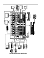
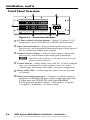
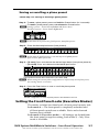
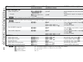
Typical SMX switcher application
HD Camera
HD-SDI Camera
1 2
MODE
Tx
Rx
OPTICAL
FOX HDSDI
1
2
BUFFERED OUTPUTS
DVD Player
DVD/VCR Combo
PCs
Compact HDTV
Camera Systems
Transceiver
Extron FOX HD-SDI
HD/SDI IN
RS232/RS422
REMOTE
®
US
LISTED
IT23
I.T.E.
L
1
OUT
3
R
3
2
1
FREEZE
4
PREVIEW
4
PROGRAM
Extron
ISS 506
3
2
1
FREEZE
MultiMatrix Switcher
R
R
5
5
3
3
2
1
2
3
L
6
6
4
LOGO 1
/BLACK
LOGO 1
/BLACK
R
4
LOGO 2
/BLACK
LOGO 2
/BLACK
L
5
Tx
Rx
OPTICAL
FOX HDSDI
1
2
BUFFERED OUTPUTS
DISSOLVE
TITLE
PIP
EFFECTS
TAKE
TRANSITION
CUT
7
CONFIG
/TINT
BRIGHT
/CONT
L
ZOOM
DETAIL
PICTURE
ADJUSTMENTS
CENTER COLOR
SIZE
L
6
8
7
3
L
R
Y
PLANE ADRESS
PLANE ADRESS
DIGITAL VIDEO
PLANE ADRESS
PLANE ADRESS
Y
1
VOLUME
OUT
L
1
11
1
R
22
IN
4
MENU
8
NEXT
C
PLANE ADRESS
ADJUST
PLANE ADRESS
PLANE ADRESS
WB VIDEO
PLANE ADRESS
S-VIDEO
ISS 506
ADJUST
1
11
1
Integration Seamless Switcher
C
OUT
L
2
22
R
L
S-VIDEO OUT
2
2
5
2
5
8
8
IN
8
4
1
7
4
2
3
3
33
3
OUT
R
4
3
3
55
L
4
R
44
55
5
5
R
L
7
3
6
66
6
L
OUT
66
R
IN
7
R
4
L
77
7
8
4
77
4
8
R
IN
Main Projection
Display
Sound Systems
L
VIDEO OUTPUTS
4
S-VIDEO OUT
6
2
44
FIBER OPTIC
IN
OUTPUTS
8
8
8
Digital Monitors
SDI / HDSDI OUTPUTS
COMPUTER OUT
33
2
HDTV Monitors
4
R
OUT
1
6
IN
7
R
3
6
6
3
5
5
WIPE
R
VIDEO INPUTS
S-VIDEO IN
4
S-VIDEO IN
7
4
4
6
L
OUT
INPUTS
FIBER OPTIC
IN
5
2
1
2
SDI / HDSDI INPUTS
COMPUTER IN
3
2
3
2
OUT
1 2
MODE
Transceiver
2
2
IN
HD/SDI IN
Extron FOX HD-SDI
POWER
12V
0.3A MAX
1
L
1
1
1
1
Extron
SMX System
100-240V , 50-60Hz
1.3A MAX.
RESET
POWER
12V
0.3A MAX
LAN
DVI Equipped PCs
LINK
ACT
Video Monitors
Video Monitors
Video Recorders
Data Monitors
Table of Contents
Chapter One • Introduction.........................................................1-1
About this Setup Guide................................................................1-2
About the SMX System MultiMatrix Switchers.................1-2
Chapter Two • Installation...........................................................2-1
Rear Panel...........................................................................................2-2
Installation and cabling..............................................................2-2
Installing/swapping the Input/Output boards.......................2-3
Front Panel Overview....................................................................2-4
Chapter Three • Front Panel Operation.............................3-1
Creating Ties......................................................................................3-2
Viewing Ties......................................................................................3-3
Muting or Unmuting Outputs. ..................................................3-4
Removing Ties...................................................................................3-4
I/O Presets...........................................................................................3-5
Saving or recalling a global preset...........................................3-6
Saving or recalling a plane preset............................................3-7
Setting the Front Panel Locks (Executive Modes).............3-7
Selecting Lock mode 2 or toggling between
mode 2 and mode 0....................................................................3-8
Selecting Lock mode 1 or toggling between
mode 2 and mode 1....................................................................3-8
Adjusting the Input Audio Level..............................................3-9
Using the front panel..................................................................3-9
Adjusting the Output Audio Volume. ..................................3-11
Using the front panel................................................................3-11
Reset Levels. ....................................................................................3-13
Reset mode uses........................................................................3-13
SMX System MultiMatrix Switchers • Table of Contents
Refer also to the SMX System MultiMatrix Switchers User’s Manual at www.extron.com.
i
Table of Contents, cont’d
Chapter Four • SIS™ Programmer's Guide.......................4-1
Selected SIS™ Commands.............................................................4-2
Establishing a network (Ethernet) connection.......................4-2
Connection time-outs..............................................................4-2
Number of connections...........................................................4-2
Verbose mode..........................................................................4-2
Host-to-switcher instructions.................................................4-3
Error messages.........................................................................4-3
EDID — Extended Display Identification Data......................4-3
SIS Command Tables......................................................................4-4
Chapter Five • Configuration and Control.....................5-1
Installing and Starting the SMX Control Program............5-2
Installing the program................................................................5-2
Starting the program..................................................................5-3
Accessing the HTML Pages..........................................................5-4
Using the Web Pages to Configure the SMX......................5-5
Status Page.............................................................................. 5-5
Configuration Page.....................................................................5-6
File Management Page...............................................................5-6
Control Page.................................................................................5-6
Appendix A • Reference Material......................................... A-1
Cabling and Connector Wiring................................................. A-2
Choosing a network cable........................................................ A-2
Terminating the network cable................................................ A-2
Wiring audio connectors........................................................... A-3
Installing the Input/Output Boards........................................ A-4
Installing new boards into an empty SMX frame................. A-4
Replacing an existing SMX I/O board..................................... A-4
All trademarks mentioned in this manual are the properties of their respective owners.
68-1452-50
Rev. A
02 09
ii
SMX System MultiMatrix Switchers • Table of Contents
Also refer to the SMX System MultiMatrix Switchers User’s Manual at www.extron.com.
SMX System MultiMatrix Switchers
1
Chapter One
Introduction
About this Manual
About the SMX System MultiMatrix Switchers
Introduction
About this Setup Guide
This setup guide helps you to easily and quickly set up,
configure, and operate your Extron SMX matrix switcher using
step by step instructions. It covers basic operations using the
front panel controls and selected Simple Instruction Set (SIS™)
commands, how to load and start the Windows®-based SMX
Control Program, and how to connect to the built-in HTML
pages for switcher operation.
N As used in this guide the terms “video model” and
“audio model” refers to any SMX switcher that switches
video and audio respectively. The terms "SMX matrix
switcher", SMX switcher", "SMX", and "switcher" are
refer to a typical SMX System MultiMatrix Switcher.
N For detailed information on the product described in this
guide, refer to the SMX System MultiMatrix Switchers
User’s Manual (also referred to as the SMX User's
Manual), available at www.extron.com, or the Extron CD.
About the SMX System MultiMatrix Switchers
The Extron SMX System MultiMatrix Switcher is a rack
mountable, modular, configurable, multi-format system
available in 3U, 4U, or 5U frames. Each frame has horizontal
rear panel slots into which optional I/O boards can be
inserted in any configuration and signal type as listed below:
Signal Type
I/O size (slots used)
I/O Connector
16x16 (2)
Composite video
BNC
8x4 (1)
8x8 (1)
S-video
BNC
8x4 (2)
8x8 (2)
16x16 (4)
SDI and HDSDI
BNC
8x4 (1)
8x8 (1)
16x16 (2)
Wideband video
BNC
8x8 (1)
16x16 (2)
4x4 (1)
8x4 (1)
8x8
H or V (1) 16x16
8x8 HV (2) H or V (2)
Sync
BNC
VGA
15-pin HD
8x4 (2)
8x8 (2)
16x16 (4)
S-video
mini DIN
8x4 (1)
8x8 (1)
16x16 (2)
DVI/DVI-Pro
DVI-I (Digital Only)
4x4 (1)
4x8 (2)
8x4 (2)
8x8 (2)
HDMI
HDMI
4x4 (1)
4x8 (2)
8x4 (2)
8x8 (2)
8x4 (1)
8x8 (1)
16x16 (2)
8x8 (1)
16x16 (2)
L
Audio (analog)
Captive screw
Fiber optic
Optical (SFP)
R
The 3U enclosure has six single board slots, the 4U has eight
and the 5U has ten slots. Each slot supports power and control
connections to the main unit controller and can be configured by
the user.
1-2
SMX System MultiMatrix Switchers • Introduction
Also refer to the SMX System MultiMatrix Switchers User’s Manual at www.extron.com.
SMX System MultiMatrix Switchers
2
Chapter Two
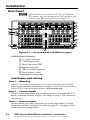
Installation
Rear Panel
Front Panel Overview
Installation
Rear Panel
N SMX switchers are available in 3U, 4U, or 5U frames.
The number, type, and arrangement of I/O boards in your
switcher may differ from that shown in figure 2-1.
2
1
3
4
IN
OUT
2
IN
OUT
3
IN
4
OUT
IN
2
1
3
6
OUT
IN
4
ADDRESS
7
OUT
IN
5
8
OUT
IN
6
FIBER OPTIC
4
SDI / HDSDI INPUTS
5
8
7
6
22
11
ADDRESS
33
44
RESET
8
77
66
1
2
3
5
6
7
8
ADDRESS
1
2
3
4
5
6
7
8
8
S-VIDEO
2
1
4
3
7
COMPUTER OUT
4
ACT LINK
55
SDI / HDSDI OUTPUTS
COMPUTER IN
RS232/RS422
LAN
IN
DIGITAL VIDEO
4
2
3
DVI-D OUTPUTS
5
OUT
FIBER OPTIC
REMOTE
3
2
1
ADDRESS
DVI-D INPUTS
1
OUT
5
S-VIDEO IN
8
7
6
2
1
ADDRESS
4
3
5
S-VIDEO OUT
8
7
6
9
S-VIDEO
2
1
6
5
4
3
Y
8
7
Y
C
INPUTS
2
1
6
5
4
3
8
7
C
VIDEO
2
1
1
L
1
R
L
2
R
4
VIDEO INPUTS
3
L
3
R
L
4
INPUTS
R
L
5
5
R
6
R
8
7
6
L
L
7
R
L
8
2
1
ADDRESS
R
10
OUTPUTS
ADDRESS
L
1
R
VIDEO OUTPUTS
L
2
R
L
3
R
11
4
3
L
4
OUTPUTS
R
L
5
R
L
6
R
L
7
R
L
8
R
12
ADDRESS
100-240V , 50-60Hz
1.2A MAX.
13
Figure 2-1 — An example of a 5U SMX rear panel
SMX Rear panel features:
a AC power connector
b LAN Ethernet port
c Reset button and LED
d Remote serial port
e - l I/O boards (optional)
m Plane address switch
(for front panel see page 2-4)
Installation and cabling
Step 1 — Mounting
Turn off or disconnect all equipment power sources and rack mount the SMX,
following the detailed instructions in chapter 2, SMX System MultiMatrix
Switchers User’s Manual found online at www.extron.com.
Step 2 — Connect inputs
Connect inputs from video and/or audio sources to the applicable I/O
board connectors marked “Inputs” (see table on page 1-2 for connector/
signal types).
Step 3 — Connect outputs
Connect audio and video output devices to the applicable I/O board
connectors marked “Outputs” (see table on page 1-2). See page A-3 for
audio connector wiring details
2-2
SMX System MultiMatrix Switchers • Installation
Also refer to the SMX System MultiMatrix Switchers User’s Manual at www.extron.com.
Step 4 — Connect control devices
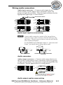
LAN Ethernet port — Connect to an Ethernet LAN or WAN via this
RJ-45 connector b to control the switcher from a remote location, using
a PC’s Internet browser. See page A-2 for network cable termination
method.
The Ethernet connection indicator LEDs marked “Link” and “Act”,
indicate the status of the SMX’s Ethernet connection. The Link LED
lights green when connected to an Ethernet LAN, and the Act LED
flickers amber, as the devices communicate.
N Do not use standard telephone cables, as they do not support Ethernet
or Fast Ethernet. Do not stretch or bend cables as transmission errors
could occur.
Remote port — For serial RS-232 or RS-422 control, connect a
host computer or control system via this 9-pin D connector d.
RS-232 protocol (default values):
• 9600 baud • 1 stop bit • no parity • 8 data bits • no flow control.
ADDRESS
N See chapter 4, “SIS™ Programming and Control”, in the SMX User’s
Manual, for definitions of the SIS commands. See chapter 5, “SMX
Software” to install and use the control software.
Step 5 — Connect power
AC power connector — Plug in a standard IEC power cord from a 100 to
240 VAC, 50 - 60 Hz power source into this receptacle a.
Step 6 — Set plane address
Set the plane address (0-15) with the 16 position (0-F) rotary encoder m.
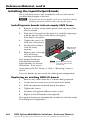
Installing/swapping the Input/Output boards
The I/O boards used in any installation will vary and can be installed
and changed as desired.
N All boards are hot-swappable, and can be installed without shutting
down the switcher and removing the power.
Follow the instructions on the card supplied with the boards.
SMX System MultiMatrix Switchers • Installation
Also refer to the SMX System MultiMatrix Switchers User’s Manual at www.extron.com.
2-3
Installation, cont’d
Front Panel Overview
1
4
I/O PLANE SELECT
0 1 2 3 4 5 6 7 8 9 10 11 12 13 14 15
INPUTS
2
CONTROL
1 2 3 4 5 6 7 8 9 10 11 12 13 14 15 16
CONFIG
1 2 3 4 5 6 7 8 9 10 11 12 13 14 15 16
ENTER
PRESET
P
O
W
E
R
OUTPUTS
VIEW
ESC
MAIN
I/O CARDS
SMX SERIES SWITCHER
3
6
5
Figure 2-3 — Front Panel features
a I/O Plane address selection buttons — Select I/O planes (0-15),
and buttons 0 and 1 select RS-232 or RS-422 communication.
b Input selection buttons — Select/switch inputs, creates and
removes ties, sets background illumination (press/hold inputs 0
and 1), or indicates output audio volume.
c Output selection buttons — Select/switch outputs, creates and
removes ties, and indicates input audio gain/attenuation.
N Input and output buttons are also used to save and recall
global and plane addresses.
d Control buttons — Enter, Preset, View, and Esc.
Used to configure
unit, save/recall presets, create/remove/view ties, audio
volume/gain adjustment, lock modes, and port configuration.
e Power status LEDs — Indicates power status for main unit and
I/O boards.
f Front panel configuration port — Connect a control system or
computer to this (RS-232) port, using an optional 9-pin D to
2.5 mm mini jack TRS RS-232 cable, part #70-335-01.
RS-232 protocol (default values): • 9600 baud • 1 stop bit
• no parity • 8 data bits • no flow control
2-4
SMX System MultiMatrix Switchers • Installation
Also refer to the SMX System MultiMatrix Switchers User’s Manual at www.extron.com.
SMX System MultiMatrix Switchers
3
Chapter Three
Front Panel Operation
Creating Ties
Viewing Ties
Muting or Unmuting Outputs
Removing Ties
I/O Presets
Setting the Front Panel Locks (Executive Modes)
Adjusting the Input Audio Level
Adjusting the Output Audio Volume
Reset Levels
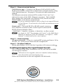
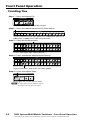
Front Panel Operation
Creating Ties
Step 1 – Press and release Esc.
C O NT R O L
ENTER PRESET
VIEW
ESC
Flashes green once. Clears pending changes.
Step 2 – Press and release the desired I/O Plane button.
I/O PLANE SELECT
0 1 2 3 4 5 6 7 8 9 10 11 12 13 14 15
I/O plane and input buttons lights green if on a video plane, red if on an
audio plane, or amber if on a video and audio plane.
Step 3 – Press desired Input button.
INPUTS
1 2 3 4 5 6 7 8 9 10 11 12 13 14 15 16
1 2 3 4 5 6 7 8 9 10 11 12 13 14 15 16
OUTPUTS
Currently tied outputs light. Input 1 turns off.
Step 4 – Press and release desired output button(s).
INPUTS
1 2 3 4 5 6 7 8 9 10 11 12 13 14 15 16
1 2 3 4 5 6 7 8 9 10 11 12 13 14 15 16
OUTPUTS
Output button blinks. Enter button also blinks (green).
Step 5 – Press and release Enter.
C O NT R O L
ENTER PRESET
VIEW
ESC
Button lights turn off. Ties are now made.
N An input can be tied to multiple outputs.
An ouptuts can only have one input.
3-2
SMX System MultiMatrix Switchers • Front Panel Operation
Also refer to the SMX System MultiMatrix Switchers User’s Manual at www.extron.com.
Viewing Ties
Step 1– Press the View button.
C O NT R O L
ENTER PRESET
VIEW
ESC
View button lights red
I/O PLANE SELECT
0 1 2 3 4 5 6 7 8 9 10 11 12 13 14 15
Last plane button used lights.
INPUTS
1 2 3 4 5 6 7 8 9 10 11 12 13 14 15 16
1 2 3 4 5 6 7 8 9 10 11 12 13 14 15 16
OUTPUTS
Untied buttons light No input buttons light.
Step 2 – To view ties for another plane, press that plane button.
I/O PLANE SELECT
0 1 2 3 4 5 6 7 8 9 10 11 12 13 14 15
Selected plane button lights
INPUTS
1 2 3 4 5 6 7 8 9 10 11 12 13 14 15 16
1 2 3 4 5 6 7 8 9 10 11 12 13 14 15 16
OUTPUTS
Untied output buttons light. Muted outputs blink
Step 3 – To view inputs tied to an output, press a tied output button.
INPUTS
1 2 3 4 5 6 7 8 9 10 11 12 13 14 15 16
1 2 3 4 5 6 7 8 9 10 11 12 13 14 15 16
OUTPUTS
Tied outputs and associated input light. Untied output buttons turn off.
Step 4 – Press and release Esc.
C O NT R O L
ENTER PRESET
VIEW
ESC
N If all outputs light, no outputs are tied.
If no outputs light, all outputs are tied.
Maximum number of outputs lit
corresponds to number of outputs
on the I/O board (4, 8, or 16).
Esc blinks green once. Button lights turn off. No changes are made to ties.
SMX System MultiMatrix Switchers • Front Panel Operation
Also refer to the SMX System MultiMatrix Switchers User’s Manual at www.extron.com.
3-3
Front Panel Operation, cont’d
Muting or unmuting Outputs
N When front panel is in lockout mode 2, the output mute
status can be viewed only. No changes (i.e. muting or
unmuting) can be made from the front panel.
Follow steps 1 – 3 of “Viewing Ties”.
Step 4 – To mute outputs, press and hold lit or unlit output button(s) for 2 seconds.
To unmute outputs, press and hold blinking output button(s) for 2 seconds.
INPUTS
1 2 3 4 5 6 7 8 9 10 11 12 13 14 15 16
1 2 3 4 5 6 7 8 9 10 11 12 13 14 15 16
OUTPUTS
Muting – Selected previously lit buttons blink, indicating outputs are now muted.
Unmuting – Previously blinking buttons remain lit, indicating those outputs are now unmuted.
N For video, only RGB is muted. Sync is not muted.
For RGBHV systems, only the R, G, and B boards are muted, and
the H and V boards remain active. All tied and untied outputs can be muted.
Step 5 – Press and release the View button.
C O NT R O L
ENTER PRESET
VIEW
ESC
All buttons turn off.
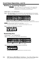
Removing Ties
Follow steps 1 – 3 of “Creating Ties”.
Step 4 – Press and release desired lit output button(s).
INPUTS
1 2 3 4 5 6 7 8 9 10 11 12 13 14 15 16
1 2 3 4 5 6 7 8 9 10 11 12 13 14 15 16
OUTPUTS
Selected outputs blink. Enter button also blinks (green).
Step 5 – Press and release Enter button to remove ties.
C O NT R O L
ENTER PRESET
VIEW
ESC
All buttons extinguish. Ties to selected ouptuts have been removed.
3-4
SMX System MultiMatrix Switchers • Front Panel Operation
Also refer to the SMX System MultiMatrix Switchers User’s Manual at www.extron.com.
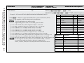
I/O Presets
The SMX has a total of thirty-two global preset (using I/O
buttons 1-16) and ten plane preset (input buttons 1-10)
addresses available.
Global preset — Saves and recalls configurations for all planes.
Use the input buttons (for presets 1 through 16) and output
buttons (for presets 17 through 32) to save any current tie
configuration to any one of the presets.
Plane preset — Saves and recalls the configurations for a specific
plane, without affecting the other plane connections. Use input
buttons 1-10 to save a plane preset.
PLANE Preset Preset Preset Preset Preset Preset Preset Preset Preset Preset
1
2
3
4
5
6
7
8
9
10
GLOBAL Preset Preset Preset Preset Preset Preset Preset Preset Preset Preset Preset Preset Preset Preset Preset Preset
1
2
3
4
5
6
7
8
9
10
11
12
13
14
15
16
INPUTS
1
2
3
4
5
6
7
8
9 10 11 12 13 14 15 16
1
2
3
4
5
6
7
8
9 10 11 12 13 14 15 16
OUTPUTS
GLOBAL Preset Preset Preset Preset Preset Preset Preset Preset Preset Preset Preset Preset Preset Preset Preset Preset
17
18
19
20
21
22
23
24
25
26
27
28
29
30
31
32
Global and plane preset addresses
Read all the notes below.
N Presets cannot be viewed from the front panel unless
recalled as the current configuration. Presets can be seen
using the Windows®-based SMX Control Program.
Refer to the SMX User's Manual.
The current configuration and all presets are stored in
non-volatile memory. When power is removed and
restored, the current configuration remains active and all
presets are retained.
Only lit presets can be recalled. When a preset is recalled,
it replaces the current configuration, and overwrites
all of the current ties in favor of its own ties. Current
configuration is lost unless previously stored as a preset.
Audio gain settings are not saved with the preset and do
not change when a preset is recalled. Only the audio and
video ties are stored and recalled.
SMX System MultiMatrix Switchers • Front Panel Operation
Also refer to the SMX System MultiMatrix Switchers User’s Manual at www.extron.com.
3-5
Front Panel Operation, cont’d
Saving or recalling a global preset
Step 1 – Press and release Esc.
C O NT R O L
ENTER PRESET
VIEW
ESC
Flashes green once and clears pending changes.
Step 2 – To save a global preset, press and hold the Preset button (for about 2 seconds).
– To recall a global preset, press and release the Preset button.
N Saving a preset – Preset button flashes red (shown here).
Recalling a preset – button lights red.
INPUTS
C O NT R O L
ENTER PRESET
VIEW
1 2 3 4 5 6 7 8 9 10 11 12 13 14 15 16
ESC
1 2 3 4 5 6 7 8 9 10 11 12 13 14 15 16
OUTPUTS
Buttons for any previously saved global presets light red (here
presets 8, 18, and 32). Any lit or unlit button can be saved to.
Step 3 – (To save) Press and release the desired input or output button (here output 5, preset 21).
– (To recall) Press and release the desired lit input or lit output button.
N When saving the current global configuration to a previously saved global preset, existing
data is overwriten.
INPUTS
1 2 3 4 5 6 7 8 9 10 11 12 13 14 15 16
1 2 3 4 5 6 7 8 9 10 11 12 13 14 15 16
OUTPUTS
Selected button flashes red. Enter button also blinks (red).
Step 4 – Press the Enter button to save or recall preset.
C O NT R O L
ENTER PRESET
VIEW
ESC
Current configuration is saved to global preset 21 and all buttons turn off.
3-6
SMX System MultiMatrix Switchers • Front Panel Operation
Also refer to the SMX System MultiMatrix Switchers User’s Manual at www.extron.com.
Saving or recalling a plane preset
Follow step 1 of “Saving or recalling a global preset”.
Step 2 – To save a plane preset, press and hold the Preset button (for 2 seconds).
– To recall a plane preset, press and release the Preset button.
N Saving a preset – Preset button flashes red (shown here).
Recalling a preset – Preset button lights red.
C O NT R O L
ENTER PRESET
VIEW
ESC
N At this time all lit presets are global presets, not plane presets.
Step 3 – Press the desired plane button (here plane 0).
I/O PLANE SELECT
0 1 2 3 4 5 6 7 8 9 10 11 12 13 14 15
Plane button lights amber.
N At this time all global presets go out and any saved plane presets
light red (here plane preset #7).
Step 4 – (To save) Press and release the desired input button (here plane preset 3).
– (To recall) Press and release the desired lit input button.
INPUTS
1 2 3 4 5 6 7 8 9 10 11 12 13 14 15 16
1 2 3 4 5 6 7 8 9 10 11 12 13 14 15 16
OUTPUTS
Selected button flashes red. Enter button also blinks (red).
N When saving the current plane configuration to a previously saved plane preset,
the existing data is overwriten.
Step 5 – Press the Enter button to save or recall the plane preset.
C O NT R O L
ENTER PRESET
VIEW
ESC
Current configuration is saved to plane preset 3 and all buttons turn off.
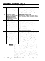
Setting the Front Panel Locks (Executive Modes)
The matrix switcher has three levels of front panel security lock.
Lock mode 0 — The front panel is completely unlocked and
all front panel controls are available. Basic and advanced
features are available.
Lock mode 1 (Executive mode) — All changes are locked from
the front panel (except for setting Lock mode 2). Only View
mode is available.
SMX System MultiMatrix Switchers • Front Panel Operation
Also refer to the SMX System MultiMatrix Switchers User’s Manual at www.extron.com.
3-7
Front Panel Operation, cont’d
Lock mode 2 (Advanced Executive mode) — Basic functions
are unlocked. Advanced features are locked and can be
viewed only (default mode).
Basic features consist of:
Making ties, saving and recalling presets, setting input audio
gain and attenuation, and changing lock modes.
Advanced features consist of:
Setting video and audio output mutes, setting audio output
volume, setting RGB delay (VGA, RGBHV boards), setting the
rear panel remote port protocol and baud rate.
N The switcher is shipped from the factory in Lock mode 2.
Selecting Lock mode 2 or toggling between
mode 2 and mode 0
N If the switcher is in Lock mode 0, this procedure selects
mode 2. Preset, View, and Esc buttons flash green twice.
If it is in Lock mode 2, this procedure selects mode 0
(unlocks the switcher). View and Esc flash green twice.
To toggle between lock mode 2 and lock mode 0
C O NT R O L
ENTER PRESET
VIEW
Press and hold for
about 2 seconds.
ENTER PRESET
VIEW
C O NT R O L
C O NT R O L
C O NT R O L
ESC
ESC
Lock mode 2:
Preset, View, and
Esc flash.
ENTER PRESET
VIEW
ESC
Press and hold for
2 seconds.
ENTER PRESET
VIEW
ESC
Lock mode 0:
View and Esc flash.
Selecting Lock mode 1 or toggling between
mode 2 and mode 1
N If the switcher is in Lock mode 1, this procedure selects
mode 2. Preset, View, and Esc buttons flash green twice.
If the switcher is in Lock mode 2, this selects mode 1.
View and Esc buttons flash green twice.
To toggle between lock mode 1 and lock mode 2
C O NT R O L
ENTER PRESET
VIEW
Press and hold for
about 2 seconds.
3-8
C O NT R O L
C O NT R O L
ESC
ENTER PRESET
VIEW
ESC
Lock mode 1:
View and Esc flash.
ENTER PRESET
VIEW
C O NT R O L
ESC
Press and hold for
2 seconds.
ENTER PRESET
VIEW
ESC
Lock mode 2:
Preset, View, and
Esc flash.
SMX System MultiMatrix Switchers • Front Panel Operation
Also refer to the SMX System MultiMatrix Switchers User’s Manual at www.extron.com.
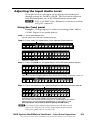
Adjusting the Input Audio Level
The audio level of each input can be displayed and adjusted
through a range of -18 dB to +24 dB. The level can be adjusted
from the front panel, or via RS-232or Ethernet connection.
N Refer to the SMX User's Manual for adjustment methods
using SIS commands.
Using the front panel
Example: Change inputs 8's audio level settings from -9dB to
+20 dB. Input 8 is on audio plane 4.
Step 1 – Press and release Esc.
Flashes green once and clears pending changes.
Step 2 – Press audio I/O plane button to be adjusted (here button 4).
I/O PLANE SELECT
0 1 2 3 4 5 6 7 8 9 10 11 12 13 14 15
Plane button lights red, indicating an audio (signal) plane.
INPUTS
1 2 3 4 5 6 7 8 9 10 11 12 13 14 15 16
1 2 3 4 5 6 7 8 9 10 11 12 13 14 15 16
OUTPUTS
I/O button 1 lights red.
Step 3 – Press and hold any I/O plane button until audio plane button flashes.
INPUTS
1 2 3 4 5 6 7 8 9 10 11 12 13 14 15 16
1 2 3 4 5 6 7 8 9 10 11 12 13 14 15 16
OUTPUTS
I/O button momentarily lights red until audio plane button flashes. I/O button 1 turns off.
I/O PLANE SELECT
0 1 2 3 4 5 6 7 8 9 10 11 12 13 14 15
Selected audio plane button flashes red and I/O button turns off.
Step 4 – Press the button for the input needing the audio level adusted (here 8).
INPUTS
1 2 3 4 5 6 7 8 9 10 11 12 13 14 15 16
1 2 3 4 5 6 7 8 9 10 11 12 13 14 15 16
OUTPUTS
Selected input button lights green, and View button lights red.
The current audio level dB is indicated by the lit and flashing output buttons.
Here buttons 1-4 lit and 5 flashing red indicates an input level of -9 dB.
(See Input Audio Level Table for button lighting and dB levels.)
N View button lights red and output buttons are red when current
audio level is negative dB, and Esc button lights red and output
buttons are green when it is positive dB.
5 – Press
and hold View
to decrease• or
Esc to
increase
audio level (here3-9
Esc).
SMXStep
System
MultiMatrix
Switchers
Front
Panel
Operation
Also refer to Cthe
MultiMatrix Switchers User’s Manual at www.extron.com.
O NSMX
T R OSystem
L
(See Input Audio Level Table for button lighting and dB levels.)
N View button lights red and output buttons are red when current
audio level is negative dB, and Esc button lights red and output
Front Panel
Operation, cont’d
buttons are green when it is positive dB.
Step 5 – Press and hold View to decrease or Esc to increase audio level (here Esc).
C O NT R O L
ENTER PRESET
VIEW
ESC
Selected control button lights red.
INPUTS
1 2 3 4 5 6 7 8 9 10 11 12 13 14 15 16
1 2 3 4 5 6 7 8 9 10 11 12 13 14 15 16
OUTPUTS
Selected input button remains lit. Outputs light, flash, or go out as the level changes.
Here the dB is raised to +20 dB. Outputs 1-10 are lit green.
(See Input Audio Level Table for button lighting and dB levels.)
Additional inputs can be adjusted by repeating steps 4 and 5.
Step 6 – Press Enter to leave the input audio level adjustment mode.
All buttons go out.
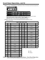
Input Audio Level Table
dB
Color
Output Buttons lit
dB
Color
Output Buttons lit
+/-
24
green
12
∆>
-1
red
1 flash
<
23
green
12 flash
∆>
-2
red
1 flash
<
22
green
11
∆>
-3
red
2 flash
<
21
green
11 flash
∆>
-4
red
2 flash
<
20
green
10
∆>
-5
red
3 flash
<
19
green
10 flash
∆>
-6
red
3 flash
<
18
green
9
∆>
-7
red
4 flash
<
17
green
9 flash
∆>
-8
red
4 flash
<
16
green
8
∆>
-9
red
5 flash
<
15
green
8 flash
∆>
-10
red
5 flash
<
14
green
7
∆>
-11
red
6 flash
<
13
green
7 flash
∆>
-12
red
6 flash
<
12
green
6
∆>
-13
red
7 flash
<
11
green
6 flash
∆>
-14
red
7 flash
<
10
green
5
∆>
-15
red
8 flash
<
9
green
5 flash
∆>
-16
red
8 flash
<
8
green
4
∆>
-17
red
9 flash
<
4 flash
∆>
-18
red
9
<
7
green
6
green
3
∆>
5
green
3 flash
∆>
4
green
2
∆>
3
green
2 flash
∆>
2
green
1
∆>
1
green
1 flash
0
3-10
+/-
> = Esc
<= View
∆>
∆
SMX System MultiMatrix Switchers • Front Panel Operation
Also refer to the SMX System MultiMatrix Switchers User’s Manual at www.extron.com.
N There is only one audio level setting per input and one per
output on an audio plane. The audio level and volume is
shared by the left and right inputs and outputs.
Audio levels and volumes are stored in nonvolatile memory.
When power is removed or restored, settings are retained.
If the audio is set to "follow all", at initial selection (step 2)
the I/O plane and tied I/O buttons light amber. When an
input or output button is held (step 3), the plane blinks red.
Adjusting the Output Audio Volume
The audio output level of each output can be displayed and
adjusted through a range of 64 steps (1 dB per step 0% to 100%).
The audio level can be adjusted from the front panel, RS-232, or
through Ethernet. Adjustment is attenuation only.
N Refer to the SMX Users Manual for adjustment methods
using SIS commands.
Front panel adjustment and viewing are only available
when the unit is in Lock mode 0.
Using the front panel
Example: Reduce output 3's (on plane 4) audio volume to 65.5%.
Follow steps 1, 2, and 3 as shown in the previous section
("Adjusting the Input Audio Level"), page 3-9.
Step 4 – Press the button for the output needing the audio volume adusted (here 3).
INPUTS
1 2 3 4 5 6 7 8 9 10 11 12 13 14 15 16
1 2 3 4 5 6 7 8 9 10 11 12 13 14 15 16
OUTPUTS
Selected output button lights green, and View button lights red.
The current audio volume is indicated by the lit and flashing input buttons.
Here input buttons 1-16 lit green indicate an output volume of 100% (0 dB attentuation).
(See Output Audio Volume Table for button lighting and volume percentages.)
Step 5 – Press and hold View to decrease or Esc to increase audio level (here View).
C O NT R O L
ENTER PRESET
VIEW
ESC
INPUTS
1 2 3 4 5 6 7 8 9 10 11 12 13 14 15 16
1 2 3 4 5 6 7 8 9 10 11 12 13 14 15 16
OUTPUTS
Selected output button remains lit. Inputs light, flash, or go out as the volume changes.
Here the volume is decreased to 65.5%. Inputs 1-10 are lit green, and 11 is flashing slowly.
Additional outputs can be adjusted by repeating steps 4 and 5.
Step 6 – Press Enter to leave the output audio volume adjustment mode.
All buttons go out.
SMX System MultiMatrix Switchers • Front Panel Operation
Also refer to the SMX System MultiMatrix Switchers User’s Manual at www.extron.com.
3-11
Front Panel Operation, cont’d
Output Audio Volume Table
Volume
%
dB
Attenuation
Buttons
lit
SIS
commnand
Volume
%
dB
Attenuation
Buttons
lit
SIS
commnand
100
0
16
plane*out#
*64V/v
52.0
32
8
plane*out#
*32V/v
98.5
1
16
63
50.5
33
8
31
97.0
2
slow
62
49.0
34
slow
30
95.5
3
slow
61
47.5
35
slow
29
94.0
4
15
60
46.0
36
7
28
92.5
5
15
59
44.5
37
7
27
91.0
6
slow
58
43.0
38
slow
26
89.5
7
slow
57
41.5
39
slow
25
88.0
8
14
56
40.0
40
6
24
86.5
9
14
55
38.5
41
6
23
85.0
10
slow
54
37.0
42
slow
22
83.5
11
slow
53
35.5
43
slow
21
82.0
12
13
52
34.0
44
5
20
80.5
13
13
51
32.5
45
5
19
79.0
14
slow
50
31.0
46
slow
18
77.5
15
slow
49
29.5
47
slow
17
76.0
16
12
48
28.0
48
4
16
74.5
17
12
47
26.5
49
4
15
73.0
18
slow
46
25.0
50
slow
14
71.5
19
slow
45
23.5
51
slow
13
70.0
20
11
44
22.0
52
3
12
68.5
21
11
43
20.5
53
3
11
67.0
22
slow
42
19.0
54
slow
10
65.5
23
slow
41
17.5
55
slow
9
64.0
24
10
40
16.0
56
2
8
62.5
25
10
39
14.5
57
2
7
61.0
26
slow
38
13.0
58
slow
6
59.5
27
slow
37
11.5
59
slow
5
58.0
28
9
36
10.0
60
1
4
56.5
29
9
35
8.5
61
1
3
55.0
30
slow
34
7.0
62
slow
2
53.5
31
slow
plane*out#
*33V/v
5.5
63
slow
1
0
76
0
0
3-12
SMX System MultiMatrix Switchers • Front Panel Operation
Also refer to the SMX System MultiMatrix Switchers User’s Manual at www.extron.com.
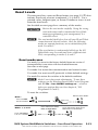
Reset Levels
The rear panel has a recessed Reset button (see page 2-2, c) that
initiates four levels of resets (numbered 1, 3, 4, and 5). Use a
pointed stylus, ballpoint pen, or Extron Tweeker to access it and
enter the reset levels.
See the table on next page for a summary of the modes.
C Review the reset modes carefully. Using the wrong
reset mode may result in unintended loss of flash
memory programming, port reassignment, or a
controller reboot.
N The reset modes listed below close all open IP and Telnet
connections and close all sockets. Also, the following
modes are separate functions, not a continuation from
mode 1 to mode 5.
If the reset button is continuously held down, the I/O
lights blink every 3 seconds and enter a different reset
level, corresponding to modes 3, 4, and 5.
Reset mode uses
Use mode 1 to revert to the factory default firmware version if
incompatibility issues arise with user-loaded firmware.
See notes on next page.
Use mode 3 to restart the communication and control events.
Use mode 4 to reset most IP protocols to their default settings.
Use mode 5 to restore the switcher to the default conditions.
N Mode 5 reset clears most adjustments. To save these
settings, use the Windows-based SMX Control Program
and the File > Save MATRIX settings as... selection
before you perform this reset (see chapter 4, “SIS
Programmer's Guide”).
To reset the switcher:
Release, then immediately
press and release again. Reset
LED flashes in confirmation.
RESET
RESET
RESET
Apply Power
Reset LED flashes once,
twice, or three times.
Modes 3, 4, and 5
Press and hold for
3, 6, or 9 seconds.
2
1
RESET
Press and hold
the Reset button.
Release Reset button.
RESET
Mode 1
SMX System MultiMatrix Switchers • Front Panel Operation
Also refer to the SMX System MultiMatrix Switchers User’s Manual at www.extron.com.
3-13
Front Panel Operation, cont’d
Reset Mode Table
Mode
Action
Result
1
Hold down the recessed
Reset button while applying
power to the switcher.
Defaults switcher to factory installed firmware.
3
Hold down the Reset
button for 3 seconds, until
the Reset LED blinks
once, then press Reset
momentarily (<1 second)
within 1 second.
Mode 3 turns events on or off.
During resetting, the Reset LED flashes 2 times if
events are starting, 3 times if events are stopping.
4
Hold down the Reset
button for 6 seconds, until
the Reset LED blinks
twice (once at 3 seconds,
again at 6 seconds) then
press Reset momentarily
(<1 second) within 1
second.
Mode 4:
• Enables ARP capability.
• Sets IP address to factory default.
• Sets subnet address to factory default.
• Sets gateway address to factory default.
• Sets port mapping to factory default.
• Turns DHCP off.
• Turns events off.
The Reset LED flashes four times in quick
succession confirming the reset.
5
Hold down the Reset button
for 9 seconds, until the
Reset LED blinks three
times (once at 3 seconds,
again at 6 seconds, and
then again at 9 seconds).
Then press Reset
momentarily (<1 second)
within 1 second.
Mode 5 performs a complete reset to factory
defaults (with the exception of the firmware):
• Does everything mode 4 does.
• Resets almost all real time adjustments:
clears all ties and presets, clears all audio or
RS-232 mutes, clears all I/O grouping,
clears all RGB delay settings to zero, and
clears all input and output audio settings.
• Resets all IP options.
• Removes/clears all files for the switcher.
The reset LED flashes four times in quick
succession confirming the reset.
Event scripting will not start if the switcher is
powered on in this mode. All user files and
settings (drivers, adjustments, IP settings, etc.)
are maintained. See notes below.
N After a mode 1 reset is performed, update the switcher’s
firmware to the latest version. Do not operate the switcher
firmware version that results from the mode 1 reset. If you
want to use the factory default firmware, you must upload
that version again.
3-14
If you do not want to update firmware, or you performed a
mode 1 reset by mistake, cycle power to the switcher to return
to the firmware version that was running before the mode 1
reset. Use the 0Q SIS command to confirm that the factory
default firmware is no longer running (look for the asterisk [*]
following the version number).
SMX System MultiMatrix Switchers • Front Panel Operation
Also refer to the SMX System MultiMatrix Switchers User’s Manual at www.extron.com.
SMX System MultiMatrix Switchers
4
Chapter Four
SIS™ Programmer's Guide
Selected SIS™ Commands
SIS Command Tables
Programmer's Guide
Selected SIS™ Commands
The switchers use Simple Instruction Set (SIS) commands for
operation and configuration. These commands can be run from
a PC connected to either of the switcher’s serial ports or the
Ethernet port. See b and d on page 2-2, and f on page 2-6, for
connection information.
N The tables that begins on the page 4-4 are a partial
list of SIS commands. For a complete list, refer to the
SMX User's Manual, chapter 4, “Programmer’s Guide”.
Establishing a network (Ethernet) connection
1.
Open a TCP socket to port 23 using the switcher’s IP
address.
N The factory default IP address is 192.168.254.254.
The switcher responds with a copyright message including
the date, the name of the product, firmware version, part
number, and the current date/time.
2.
If the switcher is not password-protected, the device is
now ready to accept SIS commands.
If the switcher is password protected, enter the appropriate
password. If accepted, the switcher responds with Login
User or Login Administrator. If the password is not
accepted, the Password prompt reappears.
Connection time-outs
The Ethernet link times out and disconnects after a designated
period of time of no communications. By default, this time-out
value is set to five minutes but the value can be changed.
N Extron recommends leaving the default time-out at five
minutes and periodically issuing the Query (Q) command
to keep the connection active or disconnecting the socket
and reopening the connection when necessary.
Number of connections
A switcher can have up to 200 simultaneous TCP connections,
including all HTTP sockets and Telnet connections. When the
limit is reached, the switcher accepts no new connections until
some have been closed. No error message or indication is given
that the limit has been reached. To maximize performance
unnecessary open sockets should be closed.
Verbose mode
Telnet connections to a switcher can be used to monitor changes
that occur on the switcher. The Telnet session must be in
verbose mode 1 or 3. See the Verbose Mode command in the SIS
command tables.
4-2
SMX System MultiMatrix Switchers • Programmer's Guide
Also refer to the SMX System MultiMatrix Switchers User’s Manual at www.extron.com.
Host-to-switcher instructions
SIS commands consist of one or more characters per command
field and do not require any special characters to begin or end
the sequence. Switcher response to an SIS command ends with
a carriage return and a line feed, which signals the end of the
character string (string = one or more characters).
] = CR/LF (carriage return/line feed)
} = Carriage return (no line feed)
Error messages
E01 = Invalid input number
E10 = Invalid command
E11 = Invalid preset number
E12 = Invalid output number
E13 = Invalid parameter
E14 = Invalid for this configuration
•
= Space character
E24 = Privilege violation
E25 = Device not present (invalid plane/slot)
E26 = Maximum number of connections exceeded
E27 = Invalid event number
E28 = Bad filename/file not found
EDID — Extended Display Identification Data
A communications protocol or instruction set for the identification of
display devices to computers using the DDC (Display Data Channel)
transmission standard. See page 4-10 for SIS commands.
EDID Minder Table — DDC source selection
SIS value X3@
Resolution
0
1
Refresh
(Hz)
SIS value X3@
Resolution
Refresh
(Hz)
Automatic
21
1280x1024
60
Output 1
22
1280x1024
75
2
Output 2
23
1365x768
60
3
Output 3
24
1365x768
75
4
Output 4
25
1366x768
60
5
Output 5
26
1366x768
75
6
Output 6
27
1400x1050
60
7
Output 7
28
1600x1200
60
8
Output 8
29
480p
60
9
640x480
60
30
576p
50
10
640x480
75
31
720p
50
11
800x600
60
32
720p
60
12
800x600
75
33
1080i
50
13
852x480
60
34
1080i
60
14
852x480
75
35
1080p
50
15
1024x768 (default)
60
36
1080p
60
16
1024x768
75
37
User assigned
17
1024x852
60
38
User assigned
18
1024x852
75
39
User assigned
19
1280x768
60
40
User assigned
20
1280x768
75
SMX System MultiMatrix Switchers • Programmer's Guide
Also refer to the SMX System MultiMatrix Switchers User’s Manual at www.extron.com.
4-3
Command
ASCII command
(host to switcher)
Response
(switcher to host)
Additional description
Also refer to the SMX System MultiMatrix Switchers User’s Manual at www.extron.com.
SMX System MultiMatrix Switchers • Programmer's Guide
Output switching by plane
N The & tie command for RGBHV and the % tie command for video can be used interchangeably.
The ! tie command can be used for switching both video signals and audio signals with the same plane address.
Tie input to an output (RGBHV)
X2@*X@*X# &
X2@OutX#•InX@•RGB]
Tie input X@ to output X# on plane
X2@ for RGB signals.
Tie input to an output (video)
X2@*X@*X# %
X2@OutX#•InX@•Vid]
Tie input X@ to output X# on plane
X2@ for video signals.
Tie input to an output (audio)
X2@*X@*X# $
X2@OutX#•InX@•Aud]
Tie input X@ to output X# on plane
X2@ for audio signals.
Tie input to an output (all)
X2@*X@*X# !
X2@OutX#•InX@•All]
Tie input X@ to output X# on plane
X2@ for all signals.
N Commands can be entered back-to-back in a string with no spaces. For example: 1*1*1&001*002*002&001*003*003&001....
The SMX supports 1-, 2-, and 3-digit numeric entries (1*1*1!, 01*02*02&, or 001*003*003%).
The & tie command for RGB and the % tie command for video can be used interchangeably.
The & read tie command for RGB and the % read tie command for video can be used interchangeably.
Tie input to all (RGBHV)
Tie input X@ to all outputs on plane
X2@*X@*&
X2@InX@•RGB]
X2@ for RGB signals.
Tie input to all (video)
Tie input X@ to all outputs on plane
X2@*X@*%
X2@InX@•Vid]
X2@ for video signals.
Tie input to all (audio)
X2@*X@*$
X2@InX@•Aud]
Tie input X@ to all outputs on plane
X2@ for audio signals.
Tie input to all (audio and video)
X2@*X@*!
X2@InX@•All]
Tie input X@ to all outputs on plane
X2@, all signals.
N
X@ = Input number
X# = Output number
X2@ = Plane number
01 – (maximum number of inputs for your model), 00 = untied
01 – (maximum number of outputs for your model)
00 – 15, 90-99 (virtual plane)
Programmer's Guide, cont’d
4-4
SIS Command Tables
Command
ASCII command
Response
Also refer to the SMX System MultiMatrix Switchers User’s Manual at www.extron.com.
SMX System MultiMatrix Switchers • Programmer's Guide
(host to switcher)
(switcher to host)
E+QX2@*X@*X# !
...X2@*X@*X#$ }
Qik ]
Additional description
Quick multiple tie
Make multiple ties
Example:
N
E+Q01*3*4!01*3*5%..
01*3*6$]
This command activates all I/O switches simultaneously.
Qik]
Make multiple ties with one command
entry.
Tie plane 01's input 3 to outputs 4, 5,
and 6.
View ties
N If the view follow-all tie command (!) is used for an output with a break-away tie, the switcher responds with an error message, E14.
View video output tie
X2@*X#%
X@]
View video input tied to output X#
on plane X2@.
(in verbose mode)
X2@OutX#•InX@•Vid]
View RGBHV output tie
X2@*X#&
X@]
View RGBHV input tied to output X#
on plane X2@.
View audio output tie
X2@*X#$
X@]
View audio input tied to output X#
on plane X2@.
X2@OutX#•InX@•Aud]
(in verbose mode)
X2@VmtX#*1]
X2@VmtX#*0]
X(]
X2@Vmt00*1]
X2@Vmt00*0]
Mute RGB/video output X#.
RGB/Video mute
RGB/video mute
RGB/video unmute
Read RGB mute
RGB/video mute per plane
RGB/video unmute per plane
N
4-5
X@ = Input number
X# = Output number
X( = Mute status X2@ = Plane number
X2@*X#*1B/b
X2@*X#*0B/b
X2@*X#B/b
X2@*1*B/b
X2@*0*B/b
Unmute RGB/video for X#.
Read RGB/video output X#.
Mute RGB/video plane.
Unmute RGB/video plane.
01 – (maximum number of inputs for your model), 00 = untied
01 – (maximum number of outputs for your model)
0 = off, 1 = on
00 – 15
ASCII command
Response
Additional description
(host to switcher)
(switcher to host)
X2@*X#*1Z/z
X2@*X#*0Z/z
X2@*X#Z/z
X2@*1*Z/z
X2@*0*Z/z
X2@AmtX#*1]
X2@AmtX#*0]
X(]
X2@Amt00*1]
X2@Amt00*0]
Mute audio output X#.
E X2@VM}
X1$1X1$2...X1$n]
Mut X2@•X1$1X1$2...X1$n]
View output mute for plane X2@.
Audio mute
Also refer to the SMX System MultiMatrix Switchers User’s Manual at www.extron.com.
SMX System MultiMatrix Switchers • Programmer's Guide
Audio mute
Audio unmute
Read audio mute
Audio mute entire plane
Audio unmute entire plane
Unmute audio for X#.
Read audio output X#.
Mute audio.
Unmute audio.
View mute
View output mutes (per plane)
(in verbose mode)
Global presets (all planes)
Save current ties as a global
preset
Example:
Recall a global preset
Example:
N
N
X1!,
SprX1!]
9,
Spr09]
X1!.
RprX1!]
Save the current set of ties as global
preset X1!. The command character is
a comma (,).
Save current tie set as preset 9.
Recall global preset X1!, and becomes
the current configuration. Command
character is a period (.).
Recall preset 5 as current configuration.
5.
Rpr05 ]
If you attempt to recall a preset that has not been saved, the SMX responds with the E11 error code.
X# = Output number
X( = Mute status
X1! = Preset number
X1$ = Video/audio mute status
X2@ = Plane address
01 to maximum number of outputs
0 = off, 1 = on
01 – 32 (global presets), 1-10 (plane presets)
0 = no mutes, 1= video mute, 2 = audio, 3 = video and audio mute
00 to 15 (for 16 planes)
Programmer's Guide, cont’d
4-6
Command
Command
ASCII command
Response
Additional description
Also refer to the SMX System MultiMatrix Switchers User’s Manual at www.extron.com.
SMX System MultiMatrix Switchers • Programmer's Guide
(host to switcher)
(switcher to host)
Save current ties as a plane
preset
X2@*X1!*0,
X2@SprX1!]
Save the current set of ties as plane
preset X1!. The command character is
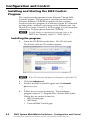
a comma (,).
Recall a plane preset
X2@*X1!*0.
X2@RprX1!]
Recall plane preset X1!, which becomes
the current configuration.
The command character is a period (.).
Write virtual plane address
EX2(,X2@1,X2@2,
...X2@nMP }
MpvX2(,X2@1,X2@2,...X2@n]
Write virtual plane address (90 to 99).
Read virtual plane address
E X2(MP }
X2@1,X2@2, ...X2@n]
Read virtual plane address.
Plane presets
Virtual (multi plane) definition
Front panel lockout (executive mode)
Lock front panel (advanced
functions)
Lock front panel (advanced and
basic functions)
Unlock front panel
2X/x
Exe2]
Enable advanced executive mode.
1X/x
Exe1]
Enable executive mode.
0X/x
X/x
Exe0]
X( ]
Disable executive mode.
View front panel lock status
X( = status of executive mode.
N
For full Lock mode details, refer to chapter 3, "Setting the Front Panel Locks (Executive Modes)" section.
N
X( = Executive mode: 0 = unlocked (all functions); 1= locked (basic and advanced); 2 = locked (advanced, default value)
X1! = Preset number
01 – 32 (global presets), 1-10 (plane presets)
X2@ = Plane number
00 – 15
X2( = Virtual plane number
90 –99
4-7
ASCII command
(host to switcher)
Response
(switcher to host)
Additional description
Information requests
Also refer to the SMX System MultiMatrix Switchers User’s Manual at www.extron.com.
SMX System MultiMatrix Switchers • Programmer's Guide
N Firmware version/part number/information is for the primary frame only.
Query firmware version
Q
X2!]
Example:
Q
Query system status
Example:
1.00]
Ver01*X2!]
The firmware version is 1.00 (sample
value).
(verbose response)
S
X2$•X2$•X2$•X2%•X2^•X2^•X7&•X7*]
S
Sts0* 3.31 4.98 24.22 +100.40 03305 03308 1 0] (verbose response)
3.31 and 4.98 are power supply voltages; 24.22 is fan voltage, 100.40
(degrees F) is the temperature, 03305 is fan 1 rpm, 03308 is fan 2 rpm, 1 is
primary power supply (OK).
VX@0XX#0AX@0XX#0• ...VX@16 XX#16AX@16XX#16•...
VX@25XX#25AX@25XX#25]
V16x16A16x16•V--X--A--X--•V--X--A--X--•V--X--A--X--•...V--X--A--X--]
The I response gives 26 parameters, the first 16 (V_x_A_x_) are plane information (planes 0-15), and the next are virtual planes 1-10 (90-99).
Query switcher information (general)
per plane (16 actual and 10 virtual)
plus board configuration
N
Query plane address per slot
I
ESTAT}
X2@(slot 1)•X2@(slot 2)•...X2@(slot 6/8/10)]
StatX2@(slot 1)•X2@(slot 2)•...X2@(slot 6/8/10)]
Example:
Slot
1 2 3 4 5 6 7 8 9 10
stat 00•01•--•02•--•--•03•--•03•03] (5U frame, 10 slots)
Slot 1 00 the board address installed in slot 1 is plane 00
Slot 2 01 the board address installed in slot 2 is plane 01
Slot 3 -- No board installed
N
X@ = Input number
X# = Output number
X2! = Firmware version number
X2@ = Plane number
X2$ = Voltage (+ or - voltage)
X2% = Temperature
01 – (maximum number of inputs for your model), 00 = untied
01 – (maximum number of outputs for your model)
X2^ = Fan speed (rpm)
X7& = Primary power supply (0 = not installed, 1 = OK
X7* = Secondary (redundant) power supply (0 = not installed, 1 = OK)
(verbose response)
Programmer's Guide, cont’d
4-8
Command
Command
ASCII command
Also refer to the SMX System MultiMatrix Switchers User’s Manual at www.extron.com.
SMX System MultiMatrix Switchers • Programmer's Guide
Query part number and slot
information
Response
Additional description
(host to switcher)
(switcher to host)
N
*N
60-xxx-yy
60-xxx-yy.X2#n1X2#n2X2#n3..... X2#n6/8/10]
Pno 60-xxx-yy.X2#n1X2#n2X2#n3.... X2#n6/8/10] (verbose response)
Example: *N Pno60-857-01.L04J07G00G00G00G15D00D15C00C15
where X2#nx = XYZ; X = type of board (B-T & X), YZ = board size (00-15)
and nx is the number of the slot the board is installed in.
N
For all combinations see tables at right.
Upper table gives X value. Lower table gives YZ value.
n = Slot 1 L04 DVI board (L) 4x4 configuration (04) - 1 slot board
n2 = Slot 2 J07 HD-SDI board (J) 8x8 configuration (07) - 1 slot board
n3 = Slot 3 G00 Slot 3 is covered by VGA board (G) no board (0)
n4 = Slot 4 G00 Slot 4 is covered by VGA board (G) no board (0)
n5 = Slot 5 G00 Slot 5 is covered by VGA board (G) no board (0)
n6 = Slot 6 G15 VGA board (G) 1616 configuration (15) - 4 slots board
n7 = Slot 7 D00 Slot 7 is covered by S-video BNC board top (D) no board (0)
n8 = Slot 8 D15 S-video BNC top board (D) 1616 configuration (15) - 2 slots (top) of 4
n9 = Slot 9 C00 Slot 9 is covered by S-video BNC board bottom (C) no board (0)
n10= Slot 10 C15 S-video BNC top board (C) 1616 configuration (15) - 2 slots (bottom) of 4
1
N
A slot response can show either no board installed (X00), or the slot
is covered by a multi slot board as shown in example above;
slots 3, 4, and 5, (G00) are covered by the 1616 VGA board in slot 6.
(X)
Board Type
(X)
Board Type
B
Video
L
DVI
C
S-video
M
DVI
D
S-video
N
DVI PRO
E
Wideband
O
HDMI
F
S-video DIN
P
FOMX 1616
G
VGA
Q
FOMX 88
H
VGA
R
RESERVED
I
Audio analog
S
RESERVED
J
SDI/HDSDI
T
RESERVED
K
Sync
X
No board installed
4-9
Reference #
(YZ)
Board Size
15
16x16
08
8x8x2
07
8x8
06
8x4
05
4x8
04
4x4
00
No board installed or slot
covered by multi slot board
Note
For sync and S-video
Refer to next slot
for size of board.
ASCII command
(host to switcher)
Response
(switcher to host)
Additional description
EDID (Extended Display Identification Data) commands
Also refer to the SMX System MultiMatrix Switchers User’s Manual at www.extron.com.
SMX System MultiMatrix Switchers • Programmer's Guide
Assign EDID data to input
EAX3)*X0!*X3@EDID}
X3)EdidAX0!*X3@]
Assign EDID data to all inputs
EA X3)*X3@*EDID}
X3)EdidA00*X3@]
Save output #1 EDID data to
user space
ESX3)*X3@EDID}
X3)EdidSX3@]
View EDID data assigment
EA X3)*X0!EDID}
Export EDID file data
EEX3)*X3@EDID}
X3@ ]
X3)EdidAX0!*X3@ ]
X6) ]
X3)EdidEX3@*X6) ]
X3)EdidIX3@ ]
Import EDID file data to user
EIX3)*X3@EDID}X6)
file location
PN For EDID table see page 4-3 in this guide or refer to the online SMX User's Manual.
N
Only applies where X3@ = 37 to 40.
Verbose mode.
Verbose mode.
Only applies where X3@ = 37 to 40.
X0! = Input number (for tie) 01 – (maximum number of inputs for your model)
X3) = Slot address 01 – 10
X3@ = EDID reference file for DDC data 00 – 40, where 15 = default, 0 = automatic, 1-8 = stored from connected
EDID monitors as reference, 9-36 = factory fixed rates, 37-40 = user definable
X6) = EDID file data block, 128 bytes of binary data
Programmer's Guide, cont’d
4-10
Command
Command
ASCII command
Response
Also refer to the SMX System MultiMatrix Switchers User’s Manual at www.extron.com.
SMX System MultiMatrix Switchers • Programmer's Guide
(host to switcher)
(switcher to host)
E X3$CI }
Ipi• X3$]
Set subnet mask
ECI}
E X1(CS}
X3$]
Ips•X1(]
View subnet mask
ECS}
X1(]
Set gateway IP address
E X3%CG}
Ipg•X3%]
Additional description
IP setup commands
Set IP address
View IP address
View gateway IP address
Set E-mail events for recipient
View E-mail events for recipient
N
X3$ = IP address in the format
###.###.###.###. Leading zeros in all the
four fields are optional for setting values.
X1( = subnet mask in the format
###.###.###.###. Leading zeros in all four
fields are optional.
X3% = gateway IP address in the format
###.###.###.###. Leading zeros in all the
four fields are optional.
ECG}
X3%]
EX4#X4!,X3),X4$,X4%EM}
X3)IpeX4#X4!*X4$*X4%]
E X4#X4!,X3),X4$EM}
X4%X4%X4%...X4%]
4-11
X1( = Subnet mask
X3) = Slot address, 00 (for F and P of X4#), 01 up to 10 (for I of X4#)
X3$ = IP address
X3% = Gateway address
X4# = Notification selection 1: I (inputs), F (fans), P (power supply)
X4! = E-mail account, 65 to 72
X4$ = Notification selection 2: If X4# = I then X4$ = 00 (all inputs) or 1 to 16.
If X4# = F then X4$ = 00 (both fans), or 01 (fan 1), or 02 (fan 2).
If X4# = P then X4$ = 00 (both power supplies), or 01 (PS 1), or 02 (PS 2).
X4% = Notify when?: 0 = no response, 1 = fail/missing, 2 = fixed/restored, 3 = both ½, 4 = suspend, 5 =resume
Also refer to the SMX System MultiMatrix Switchers User’s Manual at www.extron.com.
SMX System MultiMatrix Switchers • Programmer's Guide
ASCII command
IP setup commands cont'd
Set verbose mode
E X3&CV}
Vrb X3&]
E CV }
X3& ]
(host to switcher)
Response
(switcher to host)
Additional description
Enable or disable verbose mode and/or
tagged responses, in which additional
information is given in query response.
N The SMX can send out unsolicited information (such as a notice of a change in input or some other setting). This a verbose (wordy)
relationship between the switcher and a connected device. For a direct RS-232/422 connection, the SMX is set for verbose mode by default.
When the SMX is connected via Ethernet, verbose mode is disabled by default in order to reduce the amount of communication traffic on the
network. To use verbose mode with a switcher connected via Ethernet, you must set this mode to on each time you reconnect to the SMX.
View verbose mode
Reset commands
Reset all device settings
Clears all ties and presets, audio gain and
Zpx]
E ZXXX}
to factory settings
volume, and resets unit to factory default.
N Excludes IP settings, e.g., IP address, subnet mask, and gateway address. Does not remove file system.
N
Clears all ties and presets, and resets unit
to factory default (mode 5 reset).
Includes resetting IP address to 192.168.254.254 and subnet mask to 255.255.0.0. Firmware version remains same.
N
X3& = Verbose mode: 0 = neither verbose mode nor tagged responses enabled; 1 = verbose enabled, no tagged responses (default);
Absolute system reset
E ZQQQ}
Zpq]
2 = tagged responses enabled, verbose mode disabled; 3 = verbose mode and tagged responses enabled
Programmer's Guide, cont’d
4-12
Command
SMX System MultiMatrix Switchers
5
Chapter Five
Configuration and Control
Installing and Starting the SMX Control Program
Accessing the HTML Pages
Using the Web Pages to Configure the SMX
Configuration and Control
Installing and Starting the SMX Control
Program
The switcher can be operated via the Windows®-based SMX
Control Program. This program is contained on the Extron
Software Products CD-ROM (included with the switcher).
Install and run this program on a Windows-based PC connected
to either of the switcher’s serial ports or the Ethernet port. See
b and d, on pages 2-2 and 2-3, or f on page 2-4, for connection
information. It cannot be run from the CD-ROM.
N For full details on operating the program, refer to the
SMX User's Manual, chapter 5, “SMX Software”.
Installing the program
1.
Insert the CD-ROM into the drive. The CD self starts.
The Extron software CD window appears.
N If the CD does not self start, run Launch.exe from the CD.
2.
Click the Software tab.
3.
Scroll to the SMX Control Program and click Install.
SMX Control Program
4.
Follow the on-screen instructions. The installation
program creates a C:\Program Files\Extron\SMX folder.
Within this are created 3 icons for:
• SMX Control pgm
• SMX Help
• Uninstall SMX Control pgm
5-2
SMX System MultiMatrix Switchers • Configuration and Control
Also refer to the SMX System MultiMatrix Switchers User’s Manual at www.extron.com.
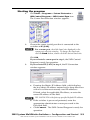
Starting the program
1.
Click Start > Programs > Extron Electronics >
SMX Control Program > SMX Control Pgm icon.
The Comm Port Selection window appears.
2.
Choose the comm (serial) port that is connected to the
switcher or IP [LAN].
N For a comm port, check the baud rate displayed in the
comm port selection window. To change the baud rate,
click the Baud button, double-click the desired baud rate.
Click OK.
If you selected a comm port in step 2, the SMX Control
Program is ready for operation.
3.
If you selected IP [LAN] in step 2, the IP Connection
window appears.
a. Examine the Matrix IP Address field, which displays
the last Matrix IP address entered and a drop down box
with a list of the most recently used IP addresses.
If listed, select the applicable IP address, or enter the
correct IP address in the field.
N 192.168.254.254 is the factory-specified default IP address.
b. If the switcher is password protected, enter the
appropriate administrator or user password in the
Password field.
c. Click Connect. The SMX Control Program is ready for
operation.
SMX System MultiMatrix Switchers • Configuration and Control 5-3
Also refer to the SMX System MultiMatrix Switchers User’s Manual at www.extron.com.
Configuration and Control, cont'd
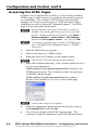
Accessing the HTML Pages
Another way to operate the switcher is via its factory-installed
HTML pages, which are always available and cannot be erased
or overwritten. The switcher’s HTML pages are accessible
through its LAN port, connected via a LAN or WAN, using a
Web browser such as Microsoft® Internet Explorer®. See d on
page 2-3 for connection information.
N If your Ethernet connection to the matrix switcher is
unstable, try turning off the proxy server in your Web
browser. In Microsoft Internet Explorer, click Tools >
Internet Options > Connections > LAN Settings,
uncheck the Use a proxy server... box, and click OK.
N For details on operating the switcher via HTML pages,
refer to the SMX Users Manual, chapter 6, “HTML
Operation”.
1.
Start the Web browser program.
2.
Click in the browser’s Address field.
3.
Enter the matrix's IP address in the Address field.
N 192.168.254.254 is the factory-specified address.
4.
Press the keyboard Enter key. The switcher checks to see if
it is password protected.
If the switcher is not password protected, it displays the
HTML start-up page. The switcher is ready for operation
via HTML remote control.
If the switcher is password protected, the switcher
displays the Connect to xx.xx.xxx.xx Password page.
N A user name entry is not required.
5-4
5.
Enter the appropriate administrator or user password in
the Password field and click OK.
6.
The switcher displays the HTML start-up page. The
switcher is ready for operation via HTML remote control.
SMX System MultiMatrix Switchers • Configuration and Control
Also refer to the SMX System MultiMatrix Switchers User’s Manual at www.extron.com.
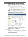
Using the Web Pages to Configure the SMX
The switcher settings can be configured via LAN /WAN web
pages using a suitable Internet browser (Internet Explorer®,
Firefox®).
To view and configure the switcher via Web pages:
1. If not already done, connect the SMX to a PC using the rear
panel RJ-45 LAN connector.
2.
Open the Internet browser on the host computer, and in
the address bar type the IP address for the SMX switcher.
N
The default IP address is 192.168.254.254. Check with
the administrator if the IP address has been changed.
The browser opens the SMX Matrix Switcher Series Default
Web Page (see screen shot), at the System Status page.
SMX default Web page — system status
There are three other pages, the Configuration page, the File
Management page, and Control page. Any of these pages can
accessed by clicking on the applicable tab.
Status page
This page allows the user to monitor the system. Settings shown
are not configurable from this page.
Click in the left column to access System Status, Physical
Configuration, and DSVP pages.
SMX System MultiMatrix Switchers • Configuration and Control 5-5
Also refer to the SMX MultiMatrix Switchers User’s Manual at www.extron.com.
Configuration and Control, cont’d
Configuration page
This page gives access to the following major settings:
System Settings, Passwords, Email Settings and Firmware
Upgrade.
Click in the left column to access each page section.
File Management page
This page allows files to be uploaded and deleted from the
server within the SMX.
Control page
This page has two sections: User Control and Presets.
The User Control section allows, for each plane, the input to
output ties to be set and viewed, input audio gain/attenuation,
and output audio volume settings to be adjusted. Audio and
video signals can be muted or unmuted per output from this
section.
In addition, where DVI boards are installed, EDID
configurations can be set from this page.
SMX Control Web page — User Control
From the Presets section, global and plane presets can be saved
and recalled.
Click in the left column to access each page section.
For full details on using the Web pages refer to the
N
SMX User's Manual, available at www.extron.com.
5-6
SMX System MultiMatrix Switchers • Configuration and Control
Also refer to the SMX System MultiMatrix Switchers User’s Manual at www.extron.com.
SMX System MultiMatrix Switchers
A
Appendix A
Reference Material
Cable and Connector Wiring
Installing the Input/Output Boards
Reference Material
N For SMX series specifications refer to the SMX User's
Manual online or on the supplied CD, or to the product's
Web page online at www.extron.com.
Cabling and Connector Wiring
Ethernet cables must be of the correct type, properly terminated
relevant to the application, and with the correct pinout.
Choosing a network cable
Use Category (CAT) 3, 4, 5, 5e, or 6 unshielded twisted pair
(UTP) or shielded twisted pair (STP) cables, terminated with
RJ-45 connectors. Ethernet cables are limited to 328' (100 m).
Half-duplex and full-duplex Ethernet connections allowed.
The cable used depends on the network speed:
•
10 Mbps (10Base-T Ethernet) requires, at a minimum,
CAT 3 UTP or STP cable.
•
100 Mbps (100Base-T Fast Ethernet) requires, at a
minimum, CAT 5 UTP or STP cable.
Terminating the network cable
Terminate as either a patch or a crossover cable (see below).
•
Patch (straight) cable — Connecting the SMX to an
Ethernet hub, router, or switcher also hosting a controlling
computer
•
Crossover cable — Direct connection between the SMX
and a controlling computer
Pins:
12345678
Straight-through Cable
(for connection to a switch, hub, or router)
End 1
Side View
Insert
Twisted
Pair Wires
Pin
1
2
3
4
5
6
7
8
Wire Color
white-orange
orange
white-green
blue
white-blue
green
white-brown
brown
RJ-45 Connector
End 2
Pin
1
2
3
4
5
6
7
8
Wire Color
white-orange
orange
white-green
blue
white-blue
green
white-brown
brown
Crossover Cable
(for direct connection to a PC)
End 1
Pin
1
2
3
4
5
6
7
8
Wire Color
white-orange
orange
white-green
blue
white-blue
green
white-brown
brown
End 2
Pin
1
2
3
4
5
6
7
8
Wire Color
white-green
green
white-orange
blue
white-blue
orange
white-brown
brown
RJ-45 connector pinout tables
A-2
SMX System MultiMatrix Switchers • Reference Material
Also refer to the SMX System MultiMatrix Switchers User’s Manual at www.extron.com.
Wiring audio connectors
Audio input connectors — Connect audio input devices
to the 3.5 mm, 5-pole captive screw connectors (up to two
groups of eight sets possible). Wire the input connector for the
appropriate signal type, as shown below.
Do not tin the wires!
R
Tip
Sleeve
Balanced Stereo Input
Unbalanced Stereo Input
L
Tip
L
R
Sleeve
Tip
Sleeve
R
Tip
Ring
Sleeve
Tip
Ring
R
Tip
Sleeve
L
L
Tip
Ring
Sleeve
Tip
Ring
Unbalanced Mono Input
Balanced Mono Input
Audio input captive screw wiring
N A mono audio connector consists of the tip and sleeve,
whereas a stereo audio connector consists of the tip, ring,
and sleeve. The tip, ring, and sleeve wires are also shown
above (balanced inputs).
See the SMX User’s Manual, chapter 3, “Operation and
Setup”, for details about setting up the audio.
Tip (+)
Ring (-)
Tip (+)
Sleeve ( )
Sleeve ( )
3.5 mm Stereo Plug Connector
RCA Connector
(balanced)
Audio connectors
Tip
R
Sleeves
Tip
Right
NO GROUND HERE
Left
R
Left
L
L
Tip
Ring
Sleeves
Tip
Ring
Audio output connectors — Connect audio output devices to
the 3.5 mm, 5-pole captive screw connectors (up to two groups
of eight sets possible). The connectors output unamplified, line
level audio. See the figure below for wiring details.
Right
NO GROUND HERE
Unbalanced Stereo Output
CAUTION
For unbalanced audio, connect the sleeve(s) to
the center contact ground. DO NOT connect
the sleeve(s) to the negative (-) contacts.
Audio output captive screw wiring
SMX System MultiMatrix Switchers • Reference Material
Also refer to the SMX System MultiMatrix Switchers User’s Manual at www.extron.com.
A-3
Reference Material, cont’d
Installing the Input/Output Boards
The I/O boards used in any installation will vary and can be
installed and changed as desired.
N All boards are hot-swappable, and can be installed without
shutting down the switcher and removing the power.
Installing new boards into an empty SMX frame
1.
Remove as many of the blanks panels from the rear of the
unit as needed.
2.
Slide the I/O board into the open slot, carefully aligning it
with the plastic slides in the frame (see figure).
Push firmly into place.
3.
Tighten the screws on
each end of the board.
R OU
Set the plane address
with the rotary
encoder.
Y
16
15
C
13
12
PLAN
MP
CO
2
7
15
6
RESET
ACT LINK
tx
LAN
10
4
9
3
8
E ADRE
PLAN
7
16
2
15
TS
6
TPU
OU
5
8
tx
EO
6
tx
7
Optional Board
(audio shown)
OU
TS
14
11
4
1
13
12
tx rx
tx
4
5
tx rx
2
3
EO
VID
SS
13
12
11
10
9
DI
3
SDI
UTS
INP
TPU
OU
/ HDS
2
VID
SS
E ADRE
O
PLAN
VIDE
AL
DIGIT
4
10
C
IDE
S-V
C
14
5
TS
TPU
12
11
O
RE
Y
14
13
Y
8
16
1
TE
MO
15
10
9
3
422
/RS
232
RS
16
11
4
R IN
UTE
9
1
SS
tx rx
Repeat steps 1 through
4 for all boards
needing installation.
8
7
14
SS
E ADRE
1
5. 3
6
5
tx rx
4.
4
T
UTE
MP
CO
2
1
E ADRE
PLAN
3
8
7
2
UTS
INP
6
L
5
1
3
US
®
SDI
DI
INP
/ HDS
L
L
2
D 17TT
LISTE /VIDEO
AUDIO ATUS
APPAR
1.3A
Hz
40V
50-60
100-2
7
L
UTS
4
L
1
MAX.
L
O
U
T
P
U
T
S
L
L
L
L
L
2
3
4
L
R
12
5
R
L
13
6
R
L
14
7
L
15
8
R
R
R
L
R
R
16
R
I
N
P
U
T
S
L
1
R
9
R
10
3
12
5
R
L
13
6
R
L
14
L
15
8
R
R
R
L
R
L
L
11
4
R
R
L
L
L
2
R
16
R
O
U
T
P
U
T
S
R
R
R
R
SS
E ADRE
PLAN
R
R
R
New output boards are
autodetected and takes
N Boards are hot swappable
(no need to remove power
approximately 20 seconds
from the unit).
to initialize. If the unit is
connected by RS-232, Telnet, or LAN, a “Reconfig” notice is
shown.
L
L
1
R
9
R
L
L
L
L
IN
I
N
P
U
T
S
10
11
R
R
Any new boards are now ready for cabling and configuration.
Replacing an existing SMX I/O board
1.
Remove any cables from the I/O board being replaced.
2.
Loosen the two outer screws and remove the board.
3.
Slide the replacement board firmly into place.
4.
Tighten the screws.
5. Set plane using plane address rotary switch.
6. Repeat 1-5 for all boards to be replaced.
New output boards are autodetected, initialized, and then ready
for cabling and configuration.
A-4
SMX System MultiMatrix Switchers • Reference Material
Also refer to the SMX System MultiMatrix Switchers User’s Manual at www.extron.com.
Extron’s Warranty
Extron Electronics warrants this product against defects in materials and workmanship
for a period of three years from the date of purchase. In the event of malfunction during
the warranty period attributable directly to faulty workmanship and/or materials,
Extron Electronics will, at its option, repair or replace said products or components,
to whatever extent it shall deem necessary to restore said product to proper operating
condition, provided that it is returned within the warranty period, with proof of
purchase and description of malfunction to:
USA, Canada, South America,
and Central America:
Extron USA
1001 East Ball Road
Anaheim, CA 92805
U.S.A.
Europe, Africa, and the Middle East:
Extron Europe
Hanzeboulevard 10
3825 PH Amersfoort
The Netherlands
Asia:
Extron Asia
135 Joo Seng Road #04-01
PM Industrial Bldg.
Singapore 368363
Singapore
Japan:
Extron Japan
Kyodo Building, 16 Ichibancho
Chiyoda-ku, Tokyo 102-0082
Japan
China:
Extron China
686 Ronghua Road,
Songjiang District
Shanghai 201611
China
Middle East:
Extron Middle East
Dubai Airport Free Zone
F12, PO Box 293666
United Arab Emirates, Dubai
This Limited Warranty does not apply if the fault has been caused by misuse, improper
handling care, electrical or mechanical abuse, abnormal operating conditions or nonExtron authorized modification to the product.
If it has been determined that the product is defective, please call Extron and ask for an
Applications Engineer at (714) 491-1500 (USA), 31.33.453.4040 (Europe), 65.6383.4400
(Asia), or 81.3.3511.7655 (Japan) to receive an RA# (Return Authorization number). This
will begin the repair process as quickly as possible.
Units must be returned insured, with shipping charges prepaid. If not insured, you
assume the risk of loss or damage during shipment. Returned units must include the
serial number and a description of the problem, as well as the name of the person to
contact in case there are any questions.
Extron Electronics makes no further warranties either expressed or implied with respect
to the product and its quality, performance, merchantability, or fitness for any particular
use. In no event will Extron Electronics be liable for direct, indirect, or consequential
damages resulting from any defect in this product even if Extron Electronics has been
advised of such damage.
Please note that laws vary from state to state and country to country, and that some
provisions of this warranty may not apply to you.
Extron USA - West
Headquarters
+800.633.9876
Inside USA / Canada Only
+1.714.491.1500
+1.714.491.1517 FAX
Extron USA - East
Extron Europe
Extron Asia
Extron Japan
Extron China
Extron Middle East
+800.633.9876
+800.3987.6673
+800.7339.8766
+81.3.3511.7655
+81.3.3511.7656 FAX
+400.883.1568
+971.4.2991800
+971.4.2991880 FAX
+1.919.863.1794
+1.919.863.1797 FAX
+31.33.453.4040
+31.33.453.4050 FAX
+65.6383.4400
+65.6383.4664 FAX
Inside USA / Canada Only
Inside Europe Only
Inside Asia Only
© 2009 Extron Electronics. All rights reserved.
Inside China Only
+86.21.3760.1568
+86.21.3760.1566 FAX