1
Frame3DD User Manual
http://frame3dd.svn.sourceforge.net/viewvc/frame3...
User manual and reference for Frame3DD: A Structural Frame Analysis Program
Department of Civil and Environmental Engineering
Edmund T. Pratt School of Engineering
Duke University - Box 90287, Durham, NC 27708-0287
Henri P. Gavin, P.E., Ph.D.,
FRAME3DD
Version 0.20100105
Frame3DD is a program for the static and dynamic structural analysis of two- and three-dimensional frames and trusses
with elastic and geometric stiffness.
Frame3DD is preferably executed from the command prompt (Windows) or shell (Linux) or terminal (OS X), as follows,
with filenames changed as required:
frame3dd inputfile.3dd outputfile.txt
Frame3DD reads a plain-text Input Data file, containing joint coordinates, frame element geometry, material moduli,
fixed joints, prescribed displacements, load information, and optionally, mass information if a modal analysis is to be carried
out.
Frame3DD appends results to a plain-text Output Data file. Results from the most recent analysis are appended to the
end of the Output Data file. Each section of the Output Data gives the date and time of the analysis, recapitulates the input
information, gives joint displacements in global coordinates, frame element end-forces in local coordinates, reactions in
global coordinates, and natural frequencies and mode shapes in global coordinates.
Frame3DD writes a Gnuplot script file used for viewing deformed frames and dynamic mode shapes. If the Output Data is
written to a file called MyResultsA.out, the Gnuplot script is written to a file called MyResultsA.plt. Graphical output may
be viewed by starting Gnuplot and typing: load 'MyResultsA.plt'.
Frame3DD can consider multiple static load cases in a single analysis. Separate output data files list the internal axial
force, shear forces, torsion, and bending moments along each frame element for each static load case.
Frame3DD may optionally interface with Matlab and with spreadsheet programs.
Frame3DD is free open-source software; you may redistribute it and/or modify it under the terms of the GNU General
Public License (GPL) as published by the Free Software Foundation. The software is distributed in the hope that it will be
useful, but without any warranty; without even the implied warranty of merchantability or fitness for a particular purpose.
See LICENSE.txt for details.
Contents
1. Getting started
2. Input Data and Output Data
3. How to install and run Frame3DD
1. Linux
2. Mac OS X
3. Windows
4. Matlab Interface
5. Spreadsheet Interface
6. FrameEd
7. Structural Modeling
1 of 33
11/09/2010 11:18 AM
Frame3DD User Manual
8.
9.
10.
11.
12.
13.
14.
15.
http://frame3dd.svn.sourceforge.net/viewvc/frame3...
Numerical Details
Input Data Format
Variable Definitions
Command-line options
Source code
Exit code index
Enhancements projected for future versions
References
1. Getting started
1.
2.
3.
4.
Read the User Manual and Reference (this file).
Download Frame3DD and save the Frame3DD folder to your Desktop (more details below).
Optionally, obtain a copy of Gnuplot for your operating system (more details below).
Open a terminal, go to the Frame3DD directory, and run the program on one of the examples using a command like
...
frame3dd examples/exE.3dd examples/exE.out
5. Open the Output Data file using a good text editor and view the Output Data.
6. Plot the structural configuration, the deformed structural shape, and mode-shapes, by starting Gnuplot, and typing
gnuplot> cd 'Desktop/Frame3DD/examples'
gnuplot> load 'exE.plt'
Observe a series of plots by hitting the Return (or Enter) key between plots.
If a dynamic analysis was performed, you will enjoy an animation of selected mode shapes.
Continue to hit the Return (or Enter) key until the last plot is displayed.
2. Input Data and Output Data
The Input Data file is a plain text file and must adhere to the format described below. Several examples are given at
http://frame3dd.sourceforge.net/. When writing your own input files, note the following points:
Comments may be placed anywhere in the file and are helpful in organizing the Input Data.
A comment begins with one of the following four characters # % ? ; and continues to the end of the line.
All commas in the Input Data are ignored.
Floating point numbers must be entered as 1.234 1234 or 1.234e3.
Arithmetic expressions such as 1.234*10^3 or 6*sin(pi/2) are not allowed in the Input Data (unless the Matlab
interface is used).
To write your own Input Data file, it may be helpful to start with an example that resembles the system you would like to
analyze. Carefully compare the graphical output of the example, the Input Data file, the Output Data file, and the Input
Data format, with the variable definitions at the end of this page.
You may edit Input Data files using a good plain text editor (vim, jEdit, nano, gedit (Linux), NotePad++ (Windows), etc.),
using the Matlab interface, or using spreadsheet programs (GoogleDocs, OpenOffice, Gnumeric, or Excel).
Details regarding the Matlab interface to Frame3DD are here.
Details regarding the spreadsheet interface to Frame3DD are here.
It might take a few tries to get your Input Data just right. Frame3DD checks the Input Data for errors prior to analyzing the
system and, where possible, displays descriptive diagnostic messages when errors are found with the Input Data.
Frame3DD generates several additional output files used in plotting deformed frames. By default, these output files
are sent to a temporary file folder. On OS X, Linux, and Unix, the location of this folder defaults to the /tmp directory. On
Windows, the location of this folder defaults to C:\WINDOWS\Temp. If you would like your output files to be sent to
another location, you can set the environment variable FRAME3DD_OUTDIR with the path to your desired temporary
output directory. The additional output files will then appear in the folder you have specified.
3. How to install and run Frame3DD
Compiled executable programs are updated with some regularity. Frame3DD installation packages are available for
download for Linux, for OS X, and for Windows operating systems as .ZIP archives. These installation .ZIP archives include:
2 of 33
11/09/2010 11:18 AM
Frame3DD User Manual
http://frame3dd.svn.sourceforge.net/viewvc/frame3...
A copy of the GPL license (LICENSE.txt)
The executable program (frame3dd) for the selected operating system (Linux, OS X, or Windows)
This manual, (doc/user-manual.html)
Some general information (README.txt)
Some Windows-specific issues (README-win32.txt)
The Matlab interface code (matlab/)
A summary of recent updates to the program (ChangeLog.txt)
A set of example Input Data files (examples/)
A separate Windows installer includes a Microstran viewer module for Frame3DD.
The date stamp at the beginning of the manual corresponds to the release date of the code.
3.1 Linux
For Linux you may install Frame3DD from a .ZIP archive or you may compile for Linux or Unix from the source code. The
following instructions install Frame3DD to the Desktop but other directories may be substituted, if so desired.
3.1.1 Installing from the .ZIP archive for Linux
1. Linux and Unix systems have good plain text editors pre-installed (vim, gedit, nano). There should be no need to
install another editor. A tutorial for vim is here.
2. Download the Frame3DD .ZIP archive (Frame3DD_VERSION_linux.zip) and save it in your Desktop.
3. If the .ZIP archive was not automatically unzipped, double-click the icon to extract it to your Desktop.
4. (Recommended) Put the Frame3DD directory in your path and set the FRAME3DD_OUTDIR location.
To do this, double-click the Home icon on the Desktop, and select View > Show Hidden Files
If you have a file called .bashrc in your home directory, open it with a double-click. Copy-and-paste the following
ten lines into the beginning of .bashrc
# for Frame3DD ... http://frame3dd.sourceforge.net/
# add Frame3DD executable directory to the path
export PATH=$PATH:$HOME/Desktop/Frame3DD/ # create a Frame3DD output directory
if [ ! -d /tmp/frame3dd_temp_$USER ]; then
mkdir /tmp/frame3dd_temp_$USER
echo "creating /tmp/frame3dd_temp_$USER for Frame3DD"
fi
# specify the Frame3DD output directory
export FRAME3DD_OUTDIR=/tmp/frame3dd_temp_$USER
... save, and exit the editor.
If you have a file named .cshrc in your home directory, open it with a double-click. Copy-and-paste the following
ten lines into the beginning of .cshrc
# for Frame3DD ... http://frame3dd.sourceforge.net/
# add Frame3DD executable directory to the path
set path = ( $path $home/Desktop/Frame3DD )
# create a Frame3DD output directory
if ( ! -d /tmp/frame3dd_temp_$user ) then
mkdir /tmp/frame3dd_temp_$user
echo "creating /tmp/frame3dd_temp_$user for Frame3DD"
endif
# specify the Frame3DD output directory
setenv FRAME3DD_OUTDIR /tmp/frame3dd_temp_$user
... save, and exit the editor.
.
5. Open a Terminal window. (Right-click on an open part of the Desktop and select Open Terminal.) Change to the
directory containing the Frame3DD example files and run an example, as follows.
cd ~/Desktop/Frame3DD/examples/ frame3dd exE.3dd exE.out Some run-time information will be displayed on the Terminal and the results of your Frame3DD analysis will have
been appended to the end of the exE.out Output Data file. Data files used primarily for plotting are stored in the
/tmp/frame3dd_temp_$USER directory.
6. You may view Output Data files and edit Input Data files using a good plain text editor (vim, gedit, nano), or a
3 of 33
11/09/2010 11:18 AM
Frame3DD User Manual
http://frame3dd.svn.sourceforge.net/viewvc/frame3...
spreadsheet program (GoogleDocs, OpenOffice, Gnumeric). For example, to read or edit the Input Data file.
Double-click the Home icon on the Desktop, navigate to the directory of your data files, right click on the Data File
and select the editor of your choice.
7. Run your own Frame3DD analyses within the Terminal window using a command like ...
frame3dd MyFrame.3dd MyResultsA.out
Use Gnuplot to view the graphical output.
1. Gnuplot is commonly pre-installed on Linux systems. If it is not, you may install it only if you have root privileges
using a command like ... sudo apt-get install gnuplot ... or by using the package manager GUI installed on
your system.
2. Start Gnuplot in the Terminal with the command:
gnuplot
3. Display the plots of your structure using Gnuplot with a command like ...
gnuplot> load 'MyResultsA.plt'
where MyResultsA.out is the name of of the Output Data file specified when running Frame3DD.
4. Hit the 'Return' key in the Terminal window to see the sequence of plots and animations until the gnuplot> prompt
returns. Or hit CTRL-C to stop the plots at the current plot.
5. To save the current plot as a PostScript file in the Frame3DD/examples directory, use the saveplot script included in
the Frame3DD/examples directory.
gnuplot> load 'saveplot'
gnuplot> !cp my-plot.ps PlotFileA.ps
6. After finishing with your plots, you can exit Gnuplot by typing ...
gnuplot> quit
3.1.2 Installing from source for Linux or Unix
The following instructions work on Ubuntu 8.10 - 9.10 and should work with minor changes on any other recent Linux or
Unix system.
1. Ensure you have Python, SCons and GCC installed on your system. On Debian-based systems it should suffice to
sudo apt-get install build-essential scons
2. If you would like to build the Microstran viewer, ensure that the package libsoqt-dev4 is installed on your system.
sudo apt-get install libsoqt-dev4
3. Download the Frame3DD source-code tarball (frame3dd-VERSION.tar.bz2) and save it in your home directory.
4. Open a Terminal, unpack the source code, enter the source directory, and build the code, as follows:
tar jxvf frame3dd-VERSION.tar.bz2
cd frame3dd-VERSION
scons
5. If you have root privileges, install build/frame3dd to /usr/local/bin/ ...
sudo scons install
or you may install frame3dd in another system directory if your choosing, such as, ...
sudo scons install INSTALL_PREFIX=/usr/bin/
6. If you do not have root privileges, you can run Frame3dd directly from the build tree:
export LD_LIBRARY_PATH=~/frame3dd-VERSION/build
export PATH=$PATH:~/frame3dd-VERSION/build
7. Copy one of the frame3dd-VERSION/examples/*.3dd files (e.g., exE.3dd) into your home directory, make sure you
have write-privileges for the file, and run one of the examples
frame3dd exE.3dd exE.out
3.2 Mac OS X
4 of 33
11/09/2010 11:18 AM
Frame3DD User Manual
http://frame3dd.svn.sourceforge.net/viewvc/frame3...
For OS X running on an Intel processor, you may install Frame3DD from a .ZIP archive or you may compile from the source
code. The following instructions install Frame3DD to the Desktop but other directories may be substituted, if so desired.
3.2.1 Installing from the .ZIP archive for OS X
1.
2.
3.
4.
Install a good plain text editor for OS X: jEdit, or Vim. A tutorial for Vim is here. Alternatively, you may use TextEdit.
Download the Frame3DD .ZIP archive (Frame3DD_VERSION_osx.zip) and save it in your Desktop.
If the .ZIP archive was not automatically unzipped, double-click the icon to extract it to your Desktop.
(Recommended) Put the Frame3DD directory in your path and set the FRAME3DD_OUTDIR location.
To do this, open your ~/.profile file using your good text editor.
* Using TextEdit, open a Terminal Applications > Utilities > Terminal and type: open -a TextEdit .profile
* Using jEdit, File > Open and type ~/.profile in the File Name: text entry bar.
* Using Vim, File > Open and select .profile from your home directory.
Copy-and-paste the following ten lines into the beginning of ~/.profile
# for Frame3DD ... http://frame3dd.sourceforge.net/
# add Frame3DD executable directory to the path
export PATH=$PATH:$HOME/Desktop/Frame3DD/
# create a Frame3DD output directory
if [ ! -d /tmp/frame3dd_temp_$USER ]; then
mkdir /tmp/frame3dd_temp_$USER
echo "creating /tmp/frame3dd_temp_$USER for Frame3DD"
fi
# specify the Frame3DD output directory
export FRAME3DD_OUTDIR=/tmp/frame3dd_temp_$USER
... save, and exit the editor.
5. Open a Terminal (Applications > Utilities > Terminal), change to the directory of example files and run an example.
cd ~/Desktop/Frame3DD/examples/ frame3dd exE.3dd exE.out Some run-time information will be displayed on the Terminal and the results of your Frame3DD analysis will have
been appended to the end of the exE.out Output Data file. Data files used primarily for plotting are stored in the
/tmp/frame3dd_temp_$USER directory.
6. You may view Output Data files and edit Input Data files using your plain text editor (jEdit, Vim, TextEdit) or a
spreadsheet program (GoogleDocs, OpenOffice).
If you use Apple's TextEdit, make sure you are in Plain Text mode ... [SHIFT] [APPLE] [T] ... or ... Format > Make
Plain Text ...
7. Run your own Frame3DD analyses within the Terminal window using a command like ...
frame3dd MyFrame.3dd MyResultsA.out
Use Gnuplot to view the graphical output.
1. From you Mac's Administrator account, first install Xcode, then install MacPorts, and finally install Gnuplot.
To install Xcode, go to the Apple Developer Connection (ADC), join ADC to create an account, log in, and
then click on Downloads > Developer Tools, and browse for the version of Xcode for your version of OS
X.
For OS X 10.4 Tiger, install Xcode 2.5 Developer Tools
For OS X 10.5 Leopard, install Xcode 3.1.4 Developer Tools
For OS X 10.6 Snow Leopard, install Xcode 3.2.1 Developer Tools
Make sure the "Unix Development" option is selected if installing Xcode 3.1.4 or 3.2.1.
To install MacPorts for your version of OS X (10.4 Tiger, 10.5 Leopard, or 10.6 Snow Leopard), follow these
instructions.
To install Gnuplot, open a terminal and type:
sudo port install gnuplot
If this is your first MacPorts package installation, it will take several minutes to complete.
2. Visualize your Frame3DD analysis output. Open a Terminal window (Applications > Utilities > Terminal) and ...
gnuplot
gnuplot> cd '~/Desktop/Frame3DD/examples'
gnuplot> load 'MyResultsA.plt'
where MyResultsA.out is the name of of the Output Data file specified when running frame3dd.
3. Hit the 'Return' key in the Terminal window to see the sequence of plots and animations until the gnuplot> prompt
returns.
4. To save the current plot as a PDF file in the Frame3DD/examples directory, use the saveplot_osx script included in
5 of 33
11/09/2010 11:18 AM
Frame3DD User Manual
http://frame3dd.svn.sourceforge.net/viewvc/frame3...
the Frame3DD/examples directory.
gnuplot> load 'saveplot_osx'
gnuplot> !cp my-plot.pdf PlotFileA.pdf
5. After finishing with your plots, you can exit Gnuplot by typing ...
gnuplot> quit
3.2.2 Compiling the source on OS X
1. Install the Xcode Developer Tools for your version of OS X as described above.
2. Download the Frame3DD source-code tarball (frame3dd-VERSION.tar.bz2) and save it in your home directory.
3. Unpack the source code, enter the source directory, and build the code, as follows:
gcc -O -o frame3dd main.c frame3dd.c frame3dd_io.c ldl_dcmp.c lu_dcmp.c coordtrans.c eig.c nrutil.c -lm
3.3 Windows
For Microsoft Windows, you may install Frame3DD from a .ZIP archive, you may use a binary installer (which may
sometimes be out of date), or you may compile from the source code. The following instructions install Frame3DD to the
Desktop but other directories may be substituted, if so desired.
3.3.1 Installing from the .ZIP archive for Windows
1. Install a good plain text editor for Windows: NotePad++, or jEdit, or gvim. A tutorial for gvim is here. Alternatively,
you may use NotePad.
2. Download the Frame3DD .ZIP archive (Frame3DD_VERSION_win32.zip) and save it to your Desktop.
3. If the .ZIP archive was not automatically unzipped, double-click the icon to extract it to your Desktop.
4. (Recommended) Put the Frame3DD directory in your path and set the PATH and FRAME3DD_OUTDIR
environment variables.
To do this, right-click My Computer > Properties > Advanced > Environment Variables
Set a new user variable name PATH with variable value %HOMEPATH%\Desktop\Frame3DD
Set a new user variable name FRAME3DD_OUTDIR with variable value %HOMEPATH%\Desktop
\Frame3DD\temp
(The Desktop\Frame3DD\temp folder should already exist.)
Detailed information on how to set environment variables in Windows is here, if you need it.
5. Open a "command prompt window" (Start > All Programs > Accessories > Command Prompt), change to
the directory of example files, and run an example, as follows:
chdir %HOMEPATH%\Desktop\Frame3DD\examples
frame3dd exE.3dd exE.out
Alternatively, you may double-click on the frame3dd program icon and enter the Input Data file name and Output
Data file name when prompted, as follows:
Please enter the input data file name: examples/exE.3dd
Please enter the output data file name: examples/exE.out
Some run-time information will be displayed on the Command Prompt window and the results of your Frame3DD
analysis will have been appended to the end of the exE.out Output Data file. Data files used primarily for plotting
are stored in the Desktop\Frame3DD\temp folder.
6. You may view Output Data files and edit Input Data files using a good plain text editor (NotePad++, jEdit, gvim), or a
spreadsheet program (GoogleDocs, OpenOffice).
7. Run your own Frame3DD analyses within the Command Prompt window using a command like ...
frame3dd MyFrame.3dd MyResultsA.out
Use Gnuplot to view the graphical output.
1.
2.
3.
4.
Download the MS-Windows version of Gnuplot and save it to your Desktop.
Navigate to Desktop > Gnuplot > bin and right click on wgnuplot to create a shortcut to your Desktop.
Clicking on the wgnuplot icon on the Desktop will start Gnuplot.
To load the plot into Gnuplot, first change directory to to location of your output files, by clicking on the ChDir
button at the top of the Gnuplot window and navigating to Desktop > Frame3DD > examples.
5. Display the plots of your structure using Gnuplot with a command like ...
gnuplot> load 'MyResultsA.plt'
6 of 33
11/09/2010 11:18 AM
Frame3DD User Manual
http://frame3dd.svn.sourceforge.net/viewvc/frame3...
where MyResultsA.out is the name of of the Output Data file specified when running Frame3DD.
6. Click OK to see the next plot or Cancel to stop with the current plot.
7. To save the current plot as a PostScript file in the Frame3DD/examples folder, use the saveplot_w32 script
included in the Frame3DD/examples folder.
gnuplot> load 'saveplot_w32'
gnuplot> !copy my-plot.ps PlotFileA.ps
3.3.2 Installing from the binary installer
1. Install a good plain text editor for Windows: NotePad++, or jEdit, or gvim. A tutorial for gvim is here. Alternatively,
you may use NotePad.
2. Download and run the binary installer (frame3dd-VERSION.exe).
3. (Recommended) Put the Frame3DD directory in your path and set the PATH and FRAME3DD_OUTDIR
environment variables.
To do this, right-click My Computer > Properties > Advanced > Environment Variables
Set a new user variable name PATH with variable value %PROGRAMFILES%\Frame3DD
Set a new user variable name FRAME3DD_OUTDIR with variable value %HOMEPATH%\Desktop
\Frame3DD\temp .
You will need to create this Temp folder: Desktop\Frame3DD\temp before running Frame3DD.
Detailed information on how to set environment variables in Windows is here, if you need it.
4. Copy one or more of the example files (eg exE.3dd) from your %PROGRAMFILES%\FRAME3DD\examples
folder into your Desktop folder
5. Open a "command prompt window" (Start > All Programs > Accessories > Command Prompt), change to the
directory of example files and run an example:
chdir %HOMEPATH%\Desktop
frame3dd exE.3dd exE.out
Some run-time information will be displayed on the Command Prompt window and the results of your Frame3DD
analysis will have been appended to the end of the exE.out Output Data file. Data files used primarily for plotting
are stored in the Desktop\Frame3DD\temp folder.
6. You may run Frame3DD, examine the analysis results, visualize the results using Gnuplot, and edit Input Data files
as described above.
3.3.3 Compiling the source on Windows
1. Install a GCC compatible compiler, such as the DJGPP gcc compiler, the LCC-win32 compiler, or the MinGW compiler.
2. Download the Frame3DD source-code tarball (frame3dd-VERSION.tar.bz2) and save it in your home directory.
3. Unpack the source code, enter the source directory, and build the code, as follows:
gcc -O -o frame3dd main.c frame3dd.c frame3dd_io.c ldl_dcmp.c lu_dcmp.c coordtrans.c eig.c nrutil.c -lm
4. Matlab Interface
Frame3DD may optionally be executed from within Matlab on any platform, via the Matlab interface function frame_3dd.m
function [D,R,F,L,Ks] = frame_3dd(XYZ,JTS,RCT,EAIJ,P,U,D)
% [D,R,F,L,Ks] = frame_3dd (XYZ,JTS,RCT,EAIJ,P,U,D)
%
% Solve a a three-dimensional frame analysis problem
%
% INPUT DATA:
%
% XYZ : a 4xJ matrix containing the XYZ coordinate of each joint
% row 1 = X-axis coordinate for each joint
% row 2 = Y-axis coordinate for each joint
% row 3 = Z-axis coordinate for each joint
% row 4 = rigid radius for each joint
%
% JTS : a 2xB matrix indicating which 2 joints each frame element connects
% row 1 = the 'starting' joint for each frame element
% row 2 = the 'ending' joint for each frame element
%
% RCT : a 6xJ matrix indicated which joints have reactions
% 0: the joint has no reaction in that degree of freedom,
7 of 33
11/09/2010 11:18 AM
Frame3DD User Manual
http://frame3dd.svn.sourceforge.net/viewvc/frame3...
% 1: the joint does have a reaction in that degree of freedom.
%
% EAIJ : a 10xB containing the section and modulus properties of each frame el.
% row 1 = Ax cross section area for each frame el.
% row 2 = Asy shear area y-directionfor each frame el.
% row 3 = Asz shear area z-directionfor each frame el.
% row 4 = Jxx torsional moment of inertia - x axis for each frame el.
% row 5 = Iyy bending moment of inertia - y axis for each frame el.
% row 6 = Izz bending moment of inertia - z axis for each frame el.
% row 7 = E elastic modulus for each frame el.
% row 8 = G shear modulus for each frame el. % row 9 = p roll angle for each frame el.
% row 10 = d mass density for each frame el.
%
% P : a 6xJ matrix containing the components of the external
% forces and moments applied to each joint.
% row 1 = Joint Force in X-direction for each joint
% row 2 = Joint Force in Y-direction for each joint
% row 3 = Joint Force in Z-direction for each joint
% row 4 = Joint Moment about X-axis for each joint
% row 5 = Joint Moment about Y-axis for each joint
% row 6 = Joint Moment about Z-axis for each joint
%
% U : a 3xB matrix containing the unif. dist. load on each frame element
% row 1 = uniform distributed load along the local element x axis
% row 2 = uniform distributed load in the local element y axis
% row 3 = uniform distributed load in the local element z axis
%
% D : a 6xJ matrix of prescribed displacements at the reaction DoF's
% row 1 = prescribed joint displ. in the X-direction for each joint
% row 2 = prescribed joint displ. in the Y-direction for each joint
% row 3 = prescribed joint displ. in the Z-direction for each joint
% row 4 = prescribed joint rot'n about the X-axis for each joint
% row 5 = prescribed joint rot'n about the Y-axis for each joint
% row 6 = prescribed joint rot'n about the Z-axis for each joint
%
% OUTPUT DATA:
%
% D : a 6xJ matrix of the deflections and rotations of each joint
% R : a 6xJ matrix of the reaction forces and moments
% F : a 12xB matrix of the end forces of each frame element
% L : a 1xB vector of the length of each frame element
% Ks : a 6Jx6J matrix of the structural stiffness matrix
The Frame3DD executable program (frame3dd on Linux or OS X, frame3dd.exe on Windows) and the matlab
interface function, frame_3dd.m must be saved to directories within your Matlab path. To display the or modify the matlab
path, use the matlab command path.
In Linux and OS X you can add the Frame3DD directory to your matlab path with the matlab commands:
path([ getenv('HOME') '/Desktop/Frame3DD' ],path) path([ getenv('HOME') '/Desktop/Frame3DD/matlab' ],path) In Windows you can add the Frame3DD directory to your matlab path with the matlab commands:
path([ getenv('USERPROFILE') '/Desktop/Frame3DD' ],path) path([ getenv('USERPROFILE') '/Desktop/Frame3DD/matlab' ],path) The matlab interface function, frame_3dd.m, executes the system command (frame3dd on Linux or OS X,
frame3dd.exe on Windows) to compute the solution.
1. The Matlab file for your problem first sets up the various matrices defining the problem for analysis and calls
frame_3dd.m
A Matlab version of Example A illustrates how to analyze problems using the Matlab interface to Frame3DD.
8 of 33
11/09/2010 11:18 AM
Frame3DD User Manual
http://frame3dd.svn.sourceforge.net/viewvc/frame3...
Matlab versions of the other examples are forthcoming.
2. frame_3dd.m writes a Frame3DD input data file called IOdata.FMM,
3. frame_3dd.m calls a system command to run the executable program frame3dd in the input data file IOdata.FMM .
4. The executable program frame3dd writes the Output Data to IOdata.OUT , and also writes IOdata_out.m,
containing the Output Data.
An m-file containing the Output Data is written whenever the frame3dd executable is run on a file ending in ".FMM",
whether or not the analysis is initiated by frame_3dd.m.
5. frame_3dd.m runs IOdata_out.m, containing the matrices D, R, F, L, and Ks,
6. frame_3dd.m returns D, R, F, L, and Ks, to the Matlab workspace, or to your Matlab function.
This m-function interface to Frame3DD is currently capable of static analyses. It does not (yet) implement the following
features of Frame3DD:
Matlab functions for graphical display of the results
gravity loading
point forces applied between the joints of a frame element
temperature loads
multiple load cases
modal analysis
matrix condensation
Adding these features would require editing the matlab inteface function, frame_3dd.m.
5. Spreadsheet Interface
Input Data for Frame3DD may be read and written using spreadsheet programs (excel, GoogleDocs, OpenOffice,
Gnumeric).
Any of the Frame3DD example Input Data files may be opened with a spreadsheet program. When editing an Input Data
file with a spreadsheet program, save it in .CSV format (with a ".CSV" filename extension).
When run on a .CSV file, Frame3DD writes results as plain text to the named Output Data file and also writes results of the
static analyses to a spreadsheet with a filename ending in ".CSV". For example, running Frame3DD as follows:
frame3dd MyFrame.CSV MyResultsA.out
results in the two Output Data files MyResultsA.out and MyResultsA_out.CSV. These .CSV files may be viewed, edited,
pre-processed, and post-processed with a spreadsheet program.
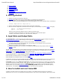
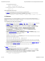
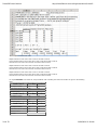
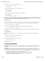
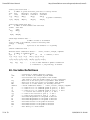
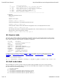
The results spreadsheet file includes an index table specifying the row numbers of each type of result.
Sections of an example results spreadsheet are shown below.
9 of 33
11/09/2010 11:18 AM
Frame3DD User Manual
http://frame3dd.svn.sourceforge.net/viewvc/frame3...
This example has three load cases.
Displacements for load case 1 start at row 21 and end at row 25.
Frame element end forces for load case 1 start at row 28 and end at row 35.
Reaction forces for load case 1 start at row 38 and end at row 42.
Displacements for load case 2 start at row 49 and end at row 53.
Frame element end forces for load case 2 start at row 56 and end at row 63.
Reaction forces for load case 2 start at row 66 and end at row 70.
Displacements for load case 3 start at row 77 and end at row 81.
Frame element end forces for load case 3 start at row 84 and end at row 91.
Reaction forces for load case 3 start at row 94 and end at row 98.
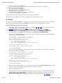
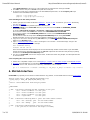
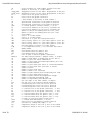
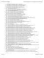
For any Frame3DD .CSV results file, the spreadsheet cells containing the result row numbers are given in the following
table.
Load Case 1
Joint Displacements
First Row Last Row
C-10
C-11
Frame Element End Forces D-10
D-11
Reaction Forces
E-11
Load Case 2
Joint Displacements
E-10
First Row Last Row
C-12
C-13
Frame Element End Forces D-12
D-13
Reaction Forces
E-13
Load Case 3
Joint Displacements
E-12
First Row Last Row
C-14
C-15
Frame Element End Forces D-14
D-15
Reaction Forces
E-15
E-14
et cetera
10 of 33
11/09/2010 11:18 AM
Frame3DD User Manual
http://frame3dd.svn.sourceforge.net/viewvc/frame3...
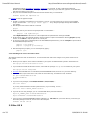
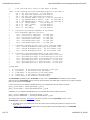
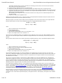
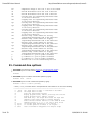
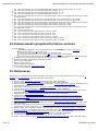
The columns of the spreadsheet results file are arranged as follows.
Displacement results are in columns A through G:
Frame element end force results are in columns A through H:
Reaction results are in columns A through G:
Modal analysis results are not (yet) written to the .CSV formatted output file.
6. FrameEd
Frame_Ed is a Windows GUI for the 20020103 version of Frame3DD (Jan 3, 2002).
The .zip file FrameEd.zip includes:
the GUI executable, Frame_Ed.exe
the frame analysis executable, Frame3d.exe, for the 20020103 version
an example input file, exG.3dd, for the 20020103 version
a template for the Input Data file, ex2002.3dd, for the 20020103 version
Differences between the 2002 and the current versions of Frame3DD are:
The
The
The
The
The
The
The
2002
2002
2002
2002
2002
2002
2002
version
version
version
version
version
version
version
does not support comments in the Input Data.
does not support multiple load cases.
does not support roll angles for frame element orientation.
uses the Jacobi method for modal analysis.
requires specification of joint masses and inertias for every joint.
does not support panning of the animation.
uses Guyan reduction for matrix condensation, to match the first mode.
Source code for FrameEd is not currently available, and development on this GUI is no longer active.
7. Structural Modeling
7.1 Units
The Output Data is formatted using floating point display, not scientific notation. To obtain the greatest number of significant
11 of 33
11/09/2010 11:18 AM
Frame3DD User Manual
http://frame3dd.svn.sourceforge.net/viewvc/frame3...
digits in the output, use units of force and length such that the modulus of elasticity occupies three to five figures before the
decimal point. For example, if the frame to be analyzed is made of steel or aluminum, use units of (kips (1000 pounds) and
inches), or (Newtons, millimeters, and tonne), or (MegaNewtons, meters, and kilotonnes).
It is recommended to write the units used in your analysis in the title of the analysis and throughout the Input Data files, as is
done in the example Input Data files.
1
1
1
1
1
inch = 25.4 millimeter = 0.0254 meter
kip = 4 448.221 6 Newton = 0.004 448 221 6 MegaNewton
kip/square inch = 6.894 757 28 Newton/square millimeter = 6.894 757 28 MegaNewton/square meter
kip/cubic inch = 0.027 679 904 593 tonne/cubic millimeter = 27.679 904 593 kilotonne/cubic meter
/deg.F = 1.8 /deg.C
7.2 Joints, Coordinates, Support Conditions and Reactions
Joint positions are specified by locations in a three-dimensional Cartesian coordinate system. Each joint has six coordinates:
three translations in the global X, Y, and Z directions and three rotations about the global X, Y, and Z axes. Optionally, joints
may be modeled as "rigid" within a sphere of radius r. The effects of finite joint sizes are modeled approximately in the
calculation of the frame element stiffness through the use of an effective beam length, which is the joint-to-joint length of
the frame element less the rigid radii on each end. All joints are fully moment resisting. Semi-rigid connections may be
modeled through the use of short frame elements at the ends of longer members.
For two-dimensional (planar) structures the global X direction is horizontal and the global Y direction is vertical. For threedimensional structures the global X and Y directions are horizontal and the global Z direction is vertical.
Joint numbers should be assigned in a systematic way, moving from one end of the structural system to the opposite end.
Support conditions are modeled by fixing the degrees of freedom collocated with reaction forces. By default, displacements
at the fixed degrees of freedom are zero. Optionally, displacements at the fixed degrees of freedom may be prescribed as a
type of loading. Elastic support conditions may be modeled by additional elements with the desired flexibility. Static reaction
forces at the fixed degrees of freedom are computed and are appended to the Output Data file.
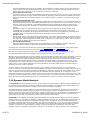
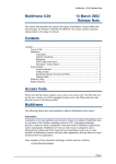
7.3 Numbering of Frame Element Starting Joints and Ending Joints
Coordinate transformations in 3D are not unique and depend upon the sequence of rotations. In some cases the orientation
of an element within a structure may not be obvious if the element has rotated by more than 90 degrees in going from the
local system to the global system. For this reason it can be helpful to define end joints in a way that requires rotations of
less than 90 degrees about any axis. Coordinate transformations in 2D are unique and these potential ambiguities are not a
concern. For 3D structures the following recommendations can help in avoiding ambiguous coordinate transformations.
Frame elements connect pairs of joints. Each frame element has a "starting joint" (element joint 1, J1) and an "ending joint"
(element joint 2, J2), as described in the Input Data format. In principle, either joint of the frame element could be joint J1
and either joint could be J2. The assignment of J1 and J2 to the frame element should not affect the results. However, to
avoid confusion in certain 3D models, the following guidelines are recommended:
In general joint J1 of the frame element should have more negative coordinates than joint J2 of the element.
12 of 33
11/09/2010 11:18 AM
Frame3DD User Manual
http://frame3dd.svn.sourceforge.net/viewvc/frame3...
More specifically, specifying element joint 1 location as (x1, y1, z1) and element joint 2 location as (x2, y2, z2),
If x1 ≠ x2 then x1 should be less then x2. Joint J2 should be toward the more positive side of the X-axis.
If x1=x2 and y1 ≠ y2 then y1 should be less then y2. Joint J2 should be toward the more positive side of the Y-axis.
If x1=x2 and y1=y2 and z1 ≠ z2 then z1 should be less then z2. Joint J2 should be toward the more positive side of
the Z-axis.
The figure below attempts to illustrate the application of these guidelines.
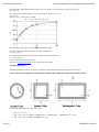
7.4 Frame Element Cross Section Properties
Cross-sectional properties of frame elements are specified in a local coordinate system, in which the x-axis of the local
coordinate system is oriented along the axis of the frame element. The local y-axis and z-axis are aligned with the principle
directions of the shape of the cross section.
7.4.1 Axial Effects
Ax is the cross-sectional area of the frame element, which is given as the cross-sectional area of the material perpendicular
to the local x-axis.
7.4.2 Shear Effects
Shear strains in frame elements are distributed in a relatively complicated manner over the cross section. Shear areas are
effective cross-sectional areas corresponding to a uniform distribution of shear strain over the cross section. The shear area
values, Asy and Asz, fully account for the non-uniform distribution of shear strain in the cross section. For slender frame
elements (in which the span-to-depth ratio is greater than 10) shear deformations contribute only slightly to the overall
structural deformation. For stocky frame elements (in which the span-to-depth ratio is less than 5) shear deformations
contribute significantly to the overall structural deformation. The shear area formulas below for circular, square, and
rectangular, cross sections provide accurate approximations of the exact values of these variables. Regardless of the
section shape, the shear areas Asy and Asz are less than the cross section area Ax.
7.4.3 Torsion Effects
13 of 33
11/09/2010 11:18 AM
Frame3DD User Manual
http://frame3dd.svn.sourceforge.net/viewvc/frame3...
Polar Moments of Inertia depend on the shape of the cross-section. For sections with a circular cross section:
Jxx = Iyy + Izz
For sections with a solid rectangular cross section (width=b, depth=d ( b < d ) ):
Jxx = Q d b3
where Q = 1/3 - 0.2244 / (d/b + 0.1607);
For more details, see page 271 of Timoshenko and Goodier (1951).
For open sections made up of thin plates (length=b, thickness=t):
Jxx = Σi [ bi ti3 / 3 ]
For closed single-box sections made up of thin plates (length=b, thickness=t):
Jxx = 4 A 2 / Σi [ bi / ti ]
where A is the area enclosed by the box.
Restraints to warping deformation are not considered in the analysis.
7.4.4 Bending Effects
The bending moments of inertia, Iyy and Izz, are the principle bending moments of inertia for the cross section.
7.4.5 Cross Section Properties of Circular Tube, Square Tube, Rectangular Tube and I-shaped Sections
Circular Tube (outer radius= R o, inner radius = R i):
Ax = π ( R o2 - R i2 )
Asy = Asz = Ax / ( 1.124235 + 0.055610(R i/R o) + 1.097134(R i/R o)2 - 0.630057(R i/R o)3 ) ± 0.5%
Asy = Asz = Ax / ( 1.06124 + 0.59546(R i/R o) ) ± 2%
14 of 33
11/09/2010 11:18 AM
Frame3DD User Manual
http://frame3dd.svn.sourceforge.net/viewvc/frame3...
Jxx = (1/2) π ( R o4 - R i4 )
Ixx = Iyy = (1/4) π ( R o4 - R i4 )
Square Tube (outer dimension = b x b, wall thickness = t):
Ax = b2 - (b - 2t)2
Asy = Asz = Ax / ( 2.08334 - 0.70154(t/b) - 8.00313(t/b)2 + 12.22572(t/b)3 ) ± 0.5%
Asy = Asz = Ax / ( 2.1186 - 1.9900(t/b) ) ± 2%
Jxx = (b - t)3 t
Izz = Iyy = (1/12) ( b4 - (b - 2t)4 )
Rectangular Tube (outer dimension = a x b, wall thickness = t):
Ax = ab - (a - 2t)(b - 2t)
Asy = Ax / ( 1.14766 + 0.28187(t/b) + 0.96199(b/a) - 2.17742(t/a) ) ± 1% ... (a > b)
Asy = Ax / ( 1.10498 - 1.98518(t/a) + 8.74762(t/a)3 + 0.99548(b/a) + 0.69146(tb/a2) - 5.36255(t2b/a3) ) ± 1% ... (b
> a)
Asz = Ax / ( 1.10498 - 1.98518(t/b) + 8.74762(t/b)3 + 0.99548(a/b) + 0.69146(ta/b2) - 5.36255(t2a/b3) ) ± 1% ... (a
> b)
Asz = Ax / ( 1.14766 + 0.28187(t/a) + 0.96199(a/b) - 2.17742(t/b) ) ± 1% ... (b > a)
Jxx = 2 t (a - t)2(b - t)2 / (a + b - 2t)
Iyy = (1/12) ( ab3 - (a - 2t)(b - 2t)3 )
Izz = (1/12) ( a3b - (a - 2t)3(b - 2t) )
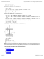
I sections (depth = d, width = b, flange thickness = t, web thickness = w):
Ax = bd - (d-2t)(b-w)
Asy = 1.64 b t
Asz = d w
Jxx = (1/3) ( 2 b t3 + d w 3 )
Iyy = (1/12) ( bd3 - (b-w)(d-2t)3 )
Izz = (1/12) ( 2 t b3 + (d-2t)w 3 )
Note: Commercial sections have rounded corners. Manufacturer specifications for cross sectional properties account for the
fact that the corners of the cross sections are rounded. Manufacturer specifcations for section properties should therefore be
used whenever available. Some tabulated section properties are provided below.
7.4.6 Cross Section Properties Of Some Common Steel Sections
Structural Steel
Steel W-section I beams #1
Steel W-section I beams #2
Steel S-section I beams
Steel Angles #1
Steel Angles #2
Steel Channels
15 of 33
11/09/2010 11:18 AM
Frame3DD User Manual
http://frame3dd.svn.sourceforge.net/viewvc/frame3...
Aluminum I beam
Aluminum Channels
7.4.7 Cross Section Properties Of Some Standard Wood Sections
Ax Asy Asz Jxx Iyy Izz
in^2 in^2 in^2 in^4 in^4 in^4
2x3 3.750 2.500 2.500 1.776 1.953 0.708
2x4 5.250 3.500 3.500 2.875 6.359 0.984
2x5 6.750 4.500 4.500 3.984 11.390 1.266
2x6 8.250 5.500 5.500 5.099 20.800 1.547
2x8 10.850 7.233 7.233 7.057 47.630 2.039
2x10 13.880 9.253 9.253 9.299 98.930 2.602
2x12 16.880 11.253 11.253 11.544 178.000 3.164
2x14 19.880 13.253 13.253 13.790 290.800 3.727
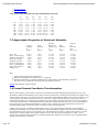
7.5 Approximate Properties of Structural Materials
Thermal Modulus
Young's Shear Expansion Mass per
Modulus Modulus Coefficient Density Density
E G a d E/d
N/mm^2 N/mm^2 /deg.C T/mm^3 mm^2/s^2
Steel A36 200000 79300 11.7e-6 7.85e-9 2.55e13
Boron Fiber-Epoxy 106000 38000 30.0e-6 2.00e-9 5.30e13
Carbon Fiber-Epoxy 83000 30000 30.0e-6 1.54e-9 5.39e13
Aluminum 2024-T4 73100 28000 23.2e-6 2.78e-9 2.63e13
Aluminum 6061-T6 68900 26000 23.6e-6 2.70e-9 2.55e13
Kevlar Fiber-Epoxy 40000 50000 30.0e-6 1.40e-9 2.86e13
Glass Fiber-Epoxy 22000 80000 30.0e-6 1.97e-9 1.12e13
Magnesium AM1000A 44800 17500 25.2e-6 1.80e-9 2.49e13
Douglas Fir 12400 4600 30.0e-6 0.50e-9 2.48e13
Note:
These material properties are approximate.
Properties of Douglas Fir vary naturally by +/- 15 percent.
Properties of Fiber-Epoxy composites depend on the volume fraction and orientations of the fibers.
The values above correspond to volume fractions of roughly 50 percent.
MatWeb lists properties of other materials.
7.6 Frame Element Coordinate Transformation
When a frame element is placed into the structure it is translated and rotated and optionally rolled about its local x-axis.
The default coordinate transformation process starts with the frame element's centroidal axis placed along the global X-axis,
and the principle axes of the cross section (the local y- and z-axes) aligned with the global Y- and Z-axes. The global Y- and
Z-axes must coincide with the principle axes of the cross section. To place the frame element in the structure, first it is
rotated about the global Y-axis, then about the global Z-axis, then 'rolled' or spun about the local x-axis. If the roll angle, p,
is zero, this process results in a transformation for which loads in the global Z-direction will cause no cross-axis bending. In
this code, this type of coordinate transformation is called "Z-axis is vertical" and is selected primarily for the sake of
visualization with Gnuplot, in which the Z-axis is vertical for all three-dimensional plots.
Another, more customary, coordinate transformation process is also implemented in the software. In the alternative
coordinate transformation process, the frame element is first rotated about the global Z-axis, then about the global Y-axis,
then rolled about the local x-axis. If the roll angle is zero, this transformation results in a frame element with no cross-axis
bending due to loads are applied in the global Y-direction. In the code, this type of transformation is called "Y-axis is
vertical." For a derivation of the alternative coordinate transformation method, refer to section 8.3 of the textbook Matrix
Analysis of Structures by A. Kassimali.
16 of 33
11/09/2010 11:18 AM
Frame3DD User Manual
http://frame3dd.svn.sourceforge.net/viewvc/frame3...
By allowing the frame element to be 'rolled' about its local x-axis during the stiffness matrix assembly process, cross-axis
bending effects may be included. Issues related to rolling of cross sections and cross-axis bending are important for threedimensional structural systems or planar structures with out-of-plane deformation, such as grillages. For planar structures
with deformations only in the plane, these issues do not arise. In addition, these issues do not arise for three-dimensional
structures made entirely of elements for which Iyy=Izz, i.e., square and circular cross sections. To reiterate, in 2D frames,
the roll angle p does not matter, and can be set to 0 (zero) for all frame elements. For frame elements with doublysymmetric sections (e.g., circular or square) the roll angle p does not matter, and can be set to 0 (zero). For 3D frames
made of non-circular or non-square sections and all frame elements are aligned with the global X, Y, or Z axes then the roll
angle p might matter but p would probably be either "0" or "90 degrees." Again, for planar structures, with no out-of-plane
bending, which lie in the global X-Y, Y-Z, or X-Z planes, and for structures made entirely of bars with Iyy=Izz, the roll angle,
p may be set to zero.
Coordinate transformations do not currently consider the effect of finite joint sizes, and are based on joint-to-joint lengths of
each frame element.
7.7 Connections
All connections in a Frame3DD analysis are moment-resisting. Internal hinges may be modeled using a short element with
low values of Jxx, Iyy, and Izz. Many connections are more realistically modeled as having some flexibility. Such semi-rigid
connections may be modeled through the inclusion of short frame elements with appropriate section and material properties
to model the behavior of the connection. Frame elements may be considered infinitely rigid within a sphere of a specified
radius, r around a joint. The effects of finite joint sizes are modeled approximately in the calculation of frame element
stiffness through the use of an effective beam length, which is the joint-to-joint length of the frame element less the rigid
radii on each end.
To analyze a structure as a "truss" with this software, specify Jxx, Iyy, and Izz to be much smaller than they would be
normally, but not zero. If the shear forces and bending moments in the structural elements are small, then the structural
model represents a "truss" approximation of the actual structure. Shear deformation effects and geometric stiffness effects
should not be incorporated if Jxx, Iyy, and Izz are made very small. See Frame3DD example A.
7.8 Shear Deformation, Geometric Stiffness, and Buckling
The Frame3DD analysis will optionally include the effects of shear deformation and/or geometric stiffness. The geometric
stiffness matrix includes the effects of axial forces on bending and warping-torsional behaviors. When both shear
deformations and geometric stiffness effects are included, the geometric stiffness matrix includes shear deformation effects.
If shear deformation effects are not to be included, simply set the shear variable to zero (0). If shear deformation effects are
neglected then the values for the shear areas Asy and Asz are not used in the calculations. Any non-zero value for Asy and
Asz will do.
To determine the buckling load of a structure, include geometric stiffness effects and increase the loads until the stiffness
matrix ceases to be positive- definite. Additionally, you may compute the fundamental natural frequency of the structure
and observe how the fundamental frequency decreases with increased loading. In principle, the fundamental frequency is
zero when the loads are at the buckling load.
If geometric stiffness effects are included in the analysis and if the loads are close to the buckling load of the structure, then
it is recommended to put two or three joints along each frame element. (i.e. divide each frame element into three or four
segments). Including these extra joints is strongly recommended if a buckling analysis is to be performed.
Whenever geometric stiffness effects are included, the analysis is non-linear and superposition does not hold. In most cases
the geometric stiffness matrix lies between the un-stressed stiffness matrix and the tangent stiffness matrix.
7.9 Loads
Seven types of static loads may be specified:
Gravity Loads
Uniformly-distributed gravity loads may be applied to each frame element in a structural model. Gravity loads are
specified in terms of the three componenets of gravitational acceleration in the structure's global X-Y-Z coordinate
system. The magnitude of the gravity load applied to a frame element is the product of the frame element's mass
density, its cross-sectional area, and the structure's gravitational acceleration resultant. The direction of the gravity
load is the same as the direction of the gravitational acceleration resultant.
Joint Loads
Concentrated static force loads and concentrated static moments may be applied to individual joints. These loads are
specified as values of point forces and concentrated moments applied to joints in the directions of the structure's
global X-Y-Z coordinate system.
Uniformly-Distributed Loads
17 of 33
11/09/2010 11:18 AM
Frame3DD User Manual
http://frame3dd.svn.sourceforge.net/viewvc/frame3...
Uniformly distributed static loads may be applied in the local element coordinate system over the entire length of a
frame element. Uniformly distributed loads are specified as values of the load per unit length applied to the frame
element in the local x direction, the local y direction, and the local z direction.
Frame Element Point Loads
Concentrated static force loads may be applied to frame elements between the joints. Up to ten frame element point
loads may be specified per frame element. These loads are specified as values of point forces applied to the frame
element in the directions of the frame element's local coordinate system at a distance x from joint J1 of the frame
element.
Trapezoidally-Distributed Loads
Trapezoidally distributed loads may be applied over a partial span of frame elements. Up to ten trapezoidal loads may
be specified per frame element. Trapezoidally distributed loads have components in the local x direction, the local y
direction, and the local z direction. Trapezoidally distributed loads are specified by the distances along the local
x-axis where the loading starts and stops, and by the value of the load at the starting location and the stopping
location.
The starting location for a trapezoidal load must be greater than 0 and less than the stopping location of the
trapezoidal load. The stopping location for a trapezoidal load must be greater than the starting value of the
trapezoidal load and less than the length of the frame element. Fixed end forces computed from trapezoidal loads
include the effects of shear deformation when shear deformation effects are incorporated.
Thermal Loads
Thermal loads assume a linear temperature gradient through cross sections. Thermal loads are specified by values for
the coefficient of thermal expansion, the depth of the section in the local y direction, the depth of the section in the
local z direction, and the temperature changes on the +y surface, the -y surface, the +z surface, and the -z surface.
Thermal loads are applied over the entire frame element.
Prescribed Displacements
Static joint displacements and rotations may be prescribed only at reaction degrees of freedom. Static joint
displacements and rotations are specified in the structure's global X-Y-Z coordinate system.
Up to thirty static load cases may be anlayzed by specifying the variable nL in the Input Data file, and by specifying the
seven types of loads for each load case, as shown in Frame3DD example A and Frame3DD example B.
More than one load of the same type on the same element or joint may be specified. For example, one or more
trapezoidally distributed loads may be applied to the same frame element in the same load case.
Whenever the average axial strain in a frame element connection (Nx/(EAx)) exceeds 0.001 (0.1%) in magnitude, a warning
message is displayed indicating the strain level and the element in question. Most structural materials yield at strains
between 0.1% and 0.2%. When this warning message is displayed the structure is likely in an overloaded condition and the
loads should be reduced. Note that this check for overloaded elements provides an approximate stress check. A more
complete stress check would compute the composite axial, shear, torsion and bending stresses and strains within each
element. Such a check requires additional cross section information: the section moduli and the section dimensions, as
described in sections 7.13 and 7.14 below.
The static stability of many structures depends upon a level of prestress within the structure. In such goemetrically
non-linear analyses, pre-stressed structres may be modeled by specifying a uniform temperature cooling in all pre-tensioned
elements. The value of the temperature change corresponding to a desired pre-stress tension force depends on the stiffness
of the components of the structural system and may be determined with a few iterations. As an initial guess, set the
temperature change to be (-T)/(a E Ax), where T is the value of the desired pre-stress tension of the frame element, a is the
coefficient of thermal expansion, E is the elastic modulus, and Ax is the cross section area of the frame element. Section 8,
below, describes how thermal (pre-stress) loads are analyzed before the response to mechanical loads is analyzed.
7.10 Dynamic Modal Analysis
The Frame3DD analysis will optionally include a dynamic analysis for natural modes of vibration. Dynamic properties may
be obtained for the un-stressed or the stressed structure by either neglecting or including geometric stiffness effects. The
mass may be modeled using either the consistent mass matrix or the lumped mass matrix.
The natural frequencies and mode-shapes of the structural frame may be computed from the stiffness and mass matrices
using either the Stodola method or the Jacobi method. The solution method and the convergence tolerance for these
iterative methods is specified in the Input Data file. If a dynamic modal analysis is to be carried out, the Input Data file must
also specify the mass density of each frame element, additional mass carried by the frame element, and extra mass or
inertia carried by the joints. A specified set of modes may be animated within Gnuplot.
Frame3DD has the capability of computing the natural frequencies and mode-shapes of frames that are fully restrained,
partially restrained, or completely un-restrained. Partially restrained frames have up to six independent rigid body modes. A
completely un-restrained frame has six independent rigid body modes. The stiffness matrix for partially restrained and
completely unrestrained structures is not invertible. Such structural configurations can not carry static loads. Furthermore,
the numerical methods used in computing the natural frequencies and mode shapes presume that the stiffness matrix is
invertible. A numerical trick called "frequency shifting" overcomes this difficulty. Presuming the mass matrix [M] is
invertible, and given a sufficiently large positive scalar value s, the matrix [[K] + s[M]] is invertible, even if the stiffness
18 of 33
11/09/2010 11:18 AM
Frame3DD User Manual
http://frame3dd.svn.sourceforge.net/viewvc/frame3...
matrix [K] is not invertible. So, for the purpose of computing the natural frequencies of frames with rigid-body modes, [K] is
replaced by [[K]+s[M]]. The desired natural frequencies are shifted by an amount equal to the "shift" variable, s, and are
shifted back, after the natural frequencies and mode shapes are found. The mode shapes are un-changed by this "shifting."
If natural frequencies are computed as "nan" (not a number) try increasing the value of the frequency shift variable either in
the Input Data file or using the -f command line option. Structural models that are partially restrained or unrestrained should
not include geometric stiffness effects.
A Sturm check is carried out to determine if any eigen-values were missed.
If a dynamic analysis is not to be performed, simply set the nM variable (the number of desired modes) to zero (0). If nM is
set to zero, Frame3DD will stop reading the Input file at this point. If nM is set to zero, there is no need to provide
numerical values for the quantities after the nM variable.
7.11 Matrix Condensation
Reduced order stiffness and mass matrices may be computed via a static condensation, Guyan reduction, or dynamic
condensation. The condensed mass and stiffness matrices are saved as text files called Kc and Mc. The Guyan reduction
method is generalized so that the condensed matrices match the fundamental frequency of the original structure exactly.
The dynamic condensation method is a pseudo-inverse-modal-matrix method, and the resulting condensed mass and
stiffness matrices may be ill-conditioned. The pseudo-inverse of the modal matrix is computed using a regularization method
which somewhat improves the conditioning of the condensed mass and stiffness matrices.
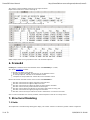
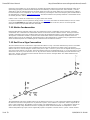
7.12 End Force Sign Convention
The frame element end forces listed in the Output data file adhere to a sign convention determined by the local coordinate
system of the frame element. The local coordinate system of the frame element has its origin at joint 1 of the frame
element. The local x-axis lies along the element, from joint 1 to joint 2. The local y and z axes are aligned with the principle
axes of the frame element cross section. The frame element end forces are designated as Nx, Vy, Vz for the axial force and
end shears in the local y and z directions; and Tx, My, Mz for the torsional moment and bending moments about the local y
and z axes. The sign convention for frame element end forces is shown in the figure below. The double-headed arrows
adhere to the "right hand rule."
The mathematical signs of the member end forces are relative to the local x-y-z axes of the frame element and designate
the direction of the force along those axes. A positive Nx at joint 1 of the member is compressive, while a negative Nx at
joint 2 is also compressive. The opposite is true for tension. The Output Data lists a "t" or a "c" along with the axial forces
(Nx) in order to help clarify whether the end force is putting the frame element into tension or compression. A frame
element with positive My at joint 1 and a negative My at joint 2 has positive curvature in the x-z plane. A frame element
19 of 33
11/09/2010 11:18 AM
Frame3DD User Manual
http://frame3dd.svn.sourceforge.net/viewvc/frame3...
with negative Mz at joint 1 and a positive Mz at joint 2 has positive curvature in the x-y plane.
7.13 Internal Frame Element Forces and Transverse Displacements
Frame3DD optionally generates output data files listing the internal axial force, shear forces, torsion, and bending
momements and transverse displacements for each frame element. These quantities are tabulated at user-specified
increments of length dx along the local x-axis of each frame element. If the x-axis increment, dx, is specified as a value of
"-1" then the calculation of internal frame element forces and transverse displacements is skipped. Otherwise a separate
internal force output file is written for each load case. For frame elements of length shorter than dx, internal forces and
displacements are calculated at x=0 and x=L. If the Frame3DD analysis Output Data file is named MyResultsA.out, then
the internal force output data files are automatically named MyResultsA.if01 for load case 1, MyResultsA.if02 for load
case 2, and so on. The internal force output data contains a section for each frame element. Each section has eleven
columns, as follows:
column
column
column
column
column
column
column
column
column
column
column
A: (x) x-axis data with a user-specified x-axis increment, dx.
B: (Nx) frame element axial force along the local x-axis
C: (Vy) frame element shear force in the local y direction
D: (Vz) frame element shear force in the local z direction
E: (Tx) frame element torsion about the local x-axis
F: (My) frame element bending moments about the local -y-axis
G: (Mz) frame element bending moments about the local z-axis
H: (Dx) frame element axial displacement in the local x direction
I: (Dy) frame element transverse displacement in the local y direction
J: (Dz) frame element transverse displacement in the local z direction
K: (Rx) frame element twist rotation about the local x-axis
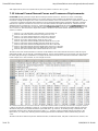
The data in the frame element internal force data file is tab-delimitted. The frame element internal force data file may be
plotted with Gnuplot, may be read by a spreadsheet program, may be read by Matlab or may be read by your own program
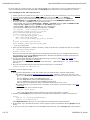
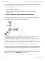
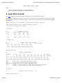
for further post-processing or visualization. An example of the first several lines of an internal force data file is shown here.
In this example, the x-axis increment, dx, has a length of 10 mm.
The header information for each frame element contains the element number (column B), the element's end joints (columns
C and D), the end joint coordinates (columns E - J), and the number of x-axis increments for the frame element (column K).
The data for this part of the header information is preceded with a '@' character, to facilitate parsing of this data file. The
last header character prior to the the internal force data is a '~' character, again to facilitate parsing of the data. In the
figure above, nx is 181 (K,10), indicating that the following element data is tabulated at 181 increments along the local
x-axis.
The data in this file is sufficient to plot the undeformed mesh, the deformed mesh, and plots of internal forces, torisons, and
20 of 33
11/09/2010 11:18 AM
Frame3DD User Manual
http://frame3dd.svn.sourceforge.net/viewvc/frame3...
moments super-imposed upon the structural mesh.
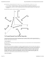
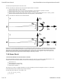
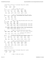
The sign convention for internal forces and transverse displacements is as follows:
Positive
Positive
Positive
Positive
Positive
internal axial force (Nx) is tensile.
internal shear forces (Vy and Vz) are in the positive y and z directions on positive x surfaces.
internal torsion (Tx) is counter-clockwise about the positive x-axis.
bending moments (My and Mz) produce positive curvature bending deformation in the x-z and x-y planes.
transverse displacements (Dy and Dz) are in the positive y and z directions.
The sign convention for internal forces is illustrated below:
Internal forces and transverse displacements are computed using numerical integration of the distributed loads on the frame
elements. A corrected trapezoidal integration method is implemented so that the internal force and transverse displacement
data match the known internal forces and joint displacements at both ends of each frame element. Internal forces and
displacements computed with a smaller increment length, dx, are more accurate. In general, a value of dx equal to one
percent to ten percent of the typical frame element length is sufficiently accurate.
7.14 Stress Check
7.14.1 Section Modulus and Torsion Shear Constant
The section properties required for elastic frame analysis are Ax, Asy, Asz, Jxx, Iyy, and Izz, as described section 7.4. To
compute stresses from the frame element end forces, the following section properties are required:
Section Area, Ax ,
Section Shear Area, Asy and Asz ,
Section Modulus, Sy and Sz , and
Torsion Shear Constant, C .
The units of Sy, Sz and C are length-cubed (like in3 or mm3). Referring to the text and figures of section 7.4, the section
moduli and torsional shear constants may be found as follows:
Circular Tube (outer radius= R o, inner radius = R i):
Sy = Sz = Iyy / R o = Izz / R o
C = Jxx / R o
21 of 33
11/09/2010 11:18 AM
Frame3DD User Manual
http://frame3dd.svn.sourceforge.net/viewvc/frame3...
Square Tube (outer dimension = b x b, wall thickness = t):
Sy = Sz = Iyy / (b/2) = Izz / (b/2)
C = 2 t ( b-t )2
Rectangular Tube (outer dimension = a x b, wall thickness = t):
Sy = Iyy / ( b/2 )
Sz = Izz / ( a/2 )
C = 2 t (a-t) (b-t)
I sections (depth = d, width = b, flange thickness = t, web thickness = w):
Sy = Iyy / ( d/2 )
Sz = Izz / ( b/2 )
C = Jxx / ( 1.28 t ) ... assuming t > w
Note: Commercial sections have rounded corners. Manufacturer specifications for cross sectional properties account for the
fact that the corners of the cross sections are rounded. Manufacturer specifcations for section properties should therefore be
used whenever available. Some tabulated section properties are provided in section 7.4.
7.14.2 Axial Stress
Given the section properties Ax, Sy, and Sz, the axial stresses at the ends of frame elements may be bounded as follows:
At end (1) of a frame element the maximum bending plus axial tensile stress in the frame element is no greater than:
-Nx1 / Ax + abs(Myy1) / Sy + abs(Mzz1) / Sz
At end (2) the maximum bending plus axial tensile stress in the frame element is no greater than:
+Nx2 / Ax + abs(Myy2) / Sy + abs(Mzz2) / Sz
A "c" indicator on "Nx" values in the Frame3DD Output Data file indicates compression. A "t" indicator on "Nx" values
indicates tension.
7.14.3 Shear Stress
Given the section properties Asy, Asz, and C, the axial stresses at the ends of frame elements may be approximated as
follows:
At end (1) the shear stress in the local y axis (on average) is:
abs(Vy1) / Asy + abs(Txx1) / C
At end (1) the shear stress in the local z axis (on average) is
abs(Vz1) / Asz + abs(Txx1) / C
And likewise for end (2).
8. Numerical Details
Frame3DD imposes no limit on the number of degrees of freedom. Dynamic memory allocation is accomplished by the
public-domain routines found in Press, W.H., et al, Numerical Recipes In C, (Cambridge, England: Cambridge University
Press, 1991).
Frame3DD analyzes the response to temperature loads alone prior to solving for the response to the combination of
temperature loads and mechanical loads. In this way, temperature loads may be used to simulate the effect of pre-tension
in structures, which can provide geometric stiffness. For each load case Frame3DD carries out the following nine steps:
1.
2.
3.
4.
22 of 33
Assemble the structural stiffness matrix for the un-stressed structure.
Compute the joint displacements due to temperature loads using a linear elastic analysis.
Compute frame element end forces from the displacements due to temperature loads.
Assemble the structural stiffness matrix again.
11/09/2010 11:18 AM
Frame3DD User Manual
5.
6.
7.
8.
9.
http://frame3dd.svn.sourceforge.net/viewvc/frame3...
If goemetric stiffness effects are to be considered, the assembly process makes use of the axial frame element
forces arising from the temperature loads.
Compute the joint displacements due to mechanical loads.
Add the joint displacements due to mechanical loads to the joint displacements due to temperature loads.
Compute frame element end forces from the displacements due to the combined temperature and mechanical loads.
If geometric stiffness effects are to be considered, carry out quasi Newton-Raphson iterations to converge upon the
displacements that satisfy equilibrium.
The assembly process makes use of the axial frame element forces arising from the combined temperature and
mechanical loads.
Compute the "RMS relative equilibrium error."
Solutions of the matrix equation, K d = f, make use of LDL' decomposition/back-substitution with sparse-matrix short-cuts
and iterative improvement for enhanced speed and accuracy.
When the program is executed, various solution errors are displayed to the screen and are written to the Output Data file.
Iterative improvements to the LDL' back-substitution make use of a quasi Newton-Raphson method:
K dD(i) = F - K D(i)
D(i+1) = D(i) + dD(i)
where
D(i) is the displacement vector at iteration i ,
K is the stiffness matrix ,
F is the applied load vector ,
dD(i) is the incremental displacement vector at iteration i , and
D(i+1) is the displacement vector at iteration i+1
At each LDL' back-substitution iteration, the equilibrium error is displayed to the screen as the "RMS equilibrium precision."
This error is the root-mean-square of dD(i). Iterations are stopped when this error decreases by less than ten percent in an
iteration.
When geometric stiffness effects are included, the solution is obtained iteratively, using a quasi Newton-Raphson method:
K(D(i)) dD(i) = F - K(D(i)) D(i)
D(i+1) = D(i) + dD(i)
where
D(i) is the displacement vector at iteration i,
K(D(i)) is the secant stiffness matrix at displacements D(i)
F is the applied load vector ,
dD(i) is the incremental displacement vector at iteration i , and
D(i+1) is the displacement vector at iteration i+1
At each Newton-Raphson iteration, the relative equilibrium error is displayed to the screen. This error is the root-meansquare of (F - K(D(i)) D(i)) divided by the root-mean-square of F. Newton-Raphson iterations stop when this error is less than
the convergence tolerance. The convergence tolerance is specified as the convergence tolerance for the modal-analysis.
The default value is 0.00001
The accuracy of the final solution is checked using a global equilibrium check and the equilibrium error is reported. The
"RMS relative equilibrium precision" is the root-mean-square of internal frame element forces and external applied loads at
every un-restrained degree of freedom normalized by the root-mean-square of the applied loads. This equilibrium error is
typically less than one part in one-billion when geometric stiffness effects are neglected. If an analysis has an "RMS relative
equilibrium precision" larger than 0.001, the results should not be trusted.
If the "RMS relative equilibrium precision" is not adequately small and geometric stiffness effects are not included in the
analysis, try including the effects of geometric stiffness by changing the geometric stiffness variable geom in the Input Data
file to 1 or by using the -gOn command line option. Conversely, if the "RMS relative equilibrium precision" is not adequately
small and geometric stiffness effects are included in the analysis, try neglecting the effects of geometric stiffness by
changing the geometric stiffness variable geom in the Input Data file to 0 or by using the -gOff command line option.
Natural frequencies and mass-normalized mode-shapes of the lower modes may be obtained using a generalized Jacobi
sub-space iteration procedure or a Stodola iteration procedure. Jacobi-subspace iterations are stopped when the frequency
convergence error is less than the specified frequency convergence tolerance. The frequency convergence error is defined
here as:
23 of 33
11/09/2010 11:18 AM
Frame3DD User Manual
http://frame3dd.svn.sourceforge.net/viewvc/frame3...
error = | fN(i) - fN(i-1) | / fN(i)
where
fN(i) is the highest natural frequency computed at iteration i ,
fN(i-1) is the highest natural frequency computed at iteration i-1 ,
9. Input Data Format
Click here to download an Input Data template, template.3dd, or copy-and-paste the text below.
The first line of the Input Data file must be a one-line title of your analysis. It is recommended to write the system of units
into the title. The title must not contain the '@' or the '~' characters, as these characters are used for parsing the Internal
Force data file.
Template Input Data file for Frame3DD - 3D structural frame analysis (N,mm,ton)
# this template indicates units of Newton, millimeter, and tonne
# other units may be specified as desired # joint data ...
nJ # number of joints
#.joint X-coord Y-coord Z-coord radius # mm mm mm mm
J[1] x[1] y[1] z[1] r[1] : : : : : J[nJ] x[nJ] y[nJ] z[nJ] r[nJ]
# reaction data ...
nR # number of joints with reactions
#.joint X Y Z XX YY ZZ 0:free, 1:fixed
J[1] Rx[1] Ry[1] Rz[1] Rxx[1] Ryy[1] Rzz[1]
: : : : : : : J[nR] Rx[nR] Ry[nR] Rz[nR] Rxx[nR] Ryy[nR] Rzz[nR]
# frame element data ...
nE # number of frame elements #.elmnt j1 j2 Ax Asy Asz Jx Iy Iz E G roll density
# . . mm^2 mm^2 mm^2 mm^4 mm^4 mm^4 MPa MPa deg tonne/mm^3
M[1] J1[1] J2[1] Ax[1] Asy[1] Asz[1] Jx[1] Iy[1] Iz[1] E[1] G[1] p[1] d[1]
: : : : : : : : : : : : :
M[nE] J1[nE] J2[nE] Ax[nE] Asy[nE] Asz[nE] Jx[nE] Iy[nE] Iz[nE] E[nE] G[nE] p[nE] d[nE]
shear # 1=Do, 0=Don't include shear deformation effects
geom # 1=Do, 0=Don't include geometric stiffness effects
exagg_static # exaggeration factor for static mesh deformations
dx # length of x-axis increment for frame element internal force data, mm
# if dx is -1 then internal force calculations are skipped
# load data ...
nL # number of static load cases, 1..30
# Begin Static Load Case 1 24 of 33
11/09/2010 11:18 AM
Frame3DD User Manual
http://frame3dd.svn.sourceforge.net/viewvc/frame3...
# gravitational acceleration for self-weight loading, mm/s^2 (global)
# gX gY gZ
# mm/s^2 mm/s^2 mm/s^2
gX gY gZ nF # number of loaded joints (global)
#.joint X-load Y-load Z-load X-mom Y-mom Z-mom
# N N N N.mm N.mm N.mm
J[1] Fx[1] Fy[1] Fz[1] Mxx[1] Myy[1] Mzz[1]
: : : : : : : J[nF] Fx[nF] Fy[nF] Fz[nF] Mxx[nF] Myy[nF] Mzz[nF]
nU # number of uniformly-distributed element loads (local)
#.elmnt X-load Y-load Z-load uniform member loads in member coordinates
# N/mm N/mm N/mm
M[1] Ux[1] Uy[1] Uz[1]
: : : : M[nU] Ux[nU] Uy[nU] Uz[nU]
nW # number of trapezoidally-distributed element loads (local)
# start stop start stop
#.elmnt loc'n loc'n load load
# mm mm N/mm N/mm
M[1] xx1[1] xx2[2] wx1[1] wx2[1] # locations and loads - local x-axis
xy1[1] xy2[2] wy1[1] wy2[1] # locations and loads - local y-axis
xz1[1] xz2[2] wz1[1] wz2[1] # locations and loads - local z-axis
: : : : :
M[nW] xx1[nW] xx2[nW] wx1[nW] wx2[nW] # x1 and x2: start and end locations
xy1[nW] xy2[nW] wy1[nW] wy2[nW] # w1 and w2: start load and end load
xz1[nW] xz2[nW] wz1[nW] wz2[nW] # 0 < x1 < x2 < L
nP # number of concentrated interior point loads (local)
#.elmnt X-load Y-load Z-load x-loc'n point loads in member coordinates M[1] Px[1] Py[1] Pz[1] x[1] : : : : : # x=distance from coordinate J1 M[nP] Px[nP] Py[nP] Pz[nP] x[nP] # 0 < x < L
nT # number of frame elements with temperature changes (local)
#.elmnt coef. y-depth z-depth deltaTy+ deltaTy- deltaTz+ deltaTz# /deg.C mm mm deg.C deg.C deg.C deg.C
M[1] a[1] hy[1] hz[1] Ty+[1] Ty-[1] Tz+[1] Tz-[1] : : : : : : : : M[nT] a[nT] hy[nT] hz[nT] Ty+[nT] Ty-[nT] Tz+[nT] Tz-[nT] nD # number of prescribed displacements nD<=nR (global)
#.jnt X-displ Y-displ Z-displ X-rot'n Y-rot'n Z-rot'n
# mm mm mm radian radian radian
J[1] Dx[1] Dy[1] Dz[3] Dxx[1] Dyy[1] Dzz[1]
: : : : : : : J[nD] Dx[nD] Dy[nD] Dz[nD] Dxx[nD] Dyy[nD] Dzz[nD]
# End Static Load Case 1
# Begin Static Load Case 2
# gravitational acceleration for self-weight loading, mm/s^2 (global)
# gX gY gZ
# mm/s^2 mm/s^2 mm/s^2
gX gY gZ nF # number of loaded joints (global)
25 of 33
11/09/2010 11:18 AM
Frame3DD User Manual
http://frame3dd.svn.sourceforge.net/viewvc/frame3...
#.joint X-load Y-load Z-load X-mom Y-mom Z-mom
# N N N N.mm N.mm N.mm
J[1] Fx[1] Fy[1] Fz[1] Mxx[1] Myy[1] Mzz[1]
: : : : : : : J[nF] Fx[nF] Fy[nF] Fz[nF] Mxx[nF] Myy[nF] Mzz[nF]
nU # number of uniformly-distributed element loads (local)
#.elmnt X-load Y-load Z-load uniform member loads in member coordinates
# N/mm N/mm N/mm
M[1] Ux[1] Uy[1] Uz[1]
: : : : M[nU] Ux[nU] Uy[nU] Uz[nU]
nW # number of trapezoidally-distributed element loads (local)
# start stop start stop
#.elmnt loc'n loc'n load load
# mm mm N/mm N/mm
M[1] xx1[1] xx2[2] wx1[1] wx2[1] # locations and loads - local x-axis
xy1[1] xy2[2] wy1[1] wy2[1] # locations and loads - local y-axis
xz1[1] xz2[2] wz1[1] wz2[1] # locations and loads - local z-axis
: : : : :
M[nW] xx1[nW] xx2[nW] wx1[nW] wx2[nW] # x1 and x2: start and end locations
xy1[nW] xy2[nW] wy1[nW] wy2[nW] # w1 and w2: start load and end load
xz1[nW] xz2[nW] wz1[nW] wz2[nW] # 0 < x1 < x2 < L
nP # number of concentrated interior point loads (local)
#.elmnt X-load Y-load Z-load x-loc'n point loads in member coordinates M[1] Px[1] Py[1] Pz[1] x[1] : : : : : # x=distance from coordinate J1 M[nP] Px[nP] Py[nP] Pz[nP] x[nP] # 0 < x < L
nT # number of frame elements with temperature changes (local)
#.elmnt coef. y-depth z-depth deltaTy+ deltaTy- deltaTz+ deltaTz# /deg.C mm mm deg.C deg.C deg.C deg.C
M[1] a[1] hy[1] hz[1] Ty+[1] Ty-[1] Tz+[1] Tz-[1] : : : : : : : : M[nT] a[nT] hy[nT] hz[nT] Ty+[nT] Ty-[nT] Tz+[nT] Tz-[nT] nD # number of prescribed displacements nD<=nR (global)
#.jnt X-displ Y-displ Z-displ X-rot'n Y-rot'n Z-rot'n
# mm mm mm radian radian radian
J[1] Dx[1] Dy[1] Dz[3] Dxx[1] Dyy[1] Dzz[1]
: : : : : : : J[nD] Dx[nD] Dy[nD] Dz[nD] Dxx[nD] Dyy[nD] Dzz[nD]
# End Static Load Case 2
# repeat up to 30 static load cases
# dynamic analysis data ...
nM # number of desired dynamic modes # if nM is set to 0 (zero) the remaining Input Data may be omitted
Mmethod # 1= Subspace-Jacobi iteration, 2= Stodola (matrix iteration) method
lump # 0= consistent mass matrix, 1= lumped mass matrix
tol # frequency convergence tolerance approx 1e-4
shift # frequency shift-factor for rigid body modes, make 0 for pos.def. [K]
exagg_modal # exaggerate modal mesh deformations
26 of 33
11/09/2010 11:18 AM
Frame3DD User Manual
http://frame3dd.svn.sourceforge.net/viewvc/frame3...
# extra joint inertia data ...
nI # number of joints with extra joint mass or rotatory inertia
#.jnt mass XX-inertia YY-inertia ZZ-inertia
# tonne tonne.mm^2 tonne.mm^2 tonne.mm^2
J[1] JMs[1] JMx[1] JMy[1] JMz[1] : : : : : # (global coordinates)
J[nI] JMs[nI] JMx[nI] JMy[nI] JMz[nI]
# extra frame element mass data ...
nX # number of frame elements with extra mass #.elmnt extra mass
# tonne
M[1] BMs[1]
: : M[nX] BMs[nE]
# mode shape animation data ...
nA # number of modes to be animated
# list of modes to be animated, sorted in increasing order anim[0] ... anim[nA]
pan # pan rate of the animation 0 = no panning
# matrix condensation data ...
Cmethod # matrix condensation method ... 0=none, 1=static, 2=Guyan, 3=dynamic
nC # number of condensed joints
#.jnt X Y Z XX YY ZZ 1: condense; 0: don't
J[1] cx[1] cy[1] cz[1] cxx[1] cyy[1] czz[1]
: : : : : : : J[nC] cx[nC] cy[nC] cz[nC] cxx[nC] cyy[nC] czz[nC]
m[1] m[2] m[3] ... # list of modes matched in dynamic condensation
# if Cmethod == 1, only mode m[1] is matched.
10. Variable Definitions
a - Coefficient of thermal expansion (1/degree)
anim - List of modes to be animated, by mode number
Ax - Cross-sectional area of a prismatic frame element
(The x-axis is along the element length, in local coordinates)
Asy - Shear area in the local y-axis of a prismatic frame element
Asz - Shear area in the local z-axis of a prismatic frame element
BMs - extra mass on a frame element, not including self mass
Cmethod - matrix condensation method ... 0=none, 1=static, 2=Guyan, 3=dynamic
cx - 1: retain X d.o.f. in condensed system at joint J; 0: don't
cy - 1: retain Y d.o.f. in condensed system at joint J; 0: don't
cz - 1: retain Z d.o.f. in condensed system at joint J; 0: don't
cxx - 1: retain X axis rotation at joint J; 0: don't
cyy - 1: retain Y axis rotation at joint J; 0: don't
czz - 1: retain Z axis rotation at joint J; 0: don't
Dx - Prescribed displacement in the global X direction
Dy - Prescribed displacement in the global Y direction
Dz - Prescribed displacement in the global Z direction
Dxx - Prescribed rotation in the global X direction
Dyy - Prescribed rotation in the global Y direction
Dzz - Prescribed rotation in the global Z direction
d - mass density of a frame element
27 of 33
11/09/2010 11:18 AM
Frame3DD User Manual
http://frame3dd.svn.sourceforge.net/viewvc/frame3...
dx - x-axis increment for frame element internal force data
E - Modulus of elasticity of a frame element
exagg_modal - Exaggeration factor for the modal displacements in the plot
exagg_static - Exaggeration factor for the static displacements in the plot
Fx - Joint load in the global X direction
Fy - Joint load in the global Y direction
Fz - Joint load in the global Z direction
G - Shear modulus of elasticity of frame element i
gX - gravitational acceleration in the global X direction
gY - gravitational acceleration in the global Y direction gZ - gravitational acceleration in the global Z direction
geom - 1: include geometric stiffness effects, 0: do not.
hy - cross-section dimension in the local y coordinate dir.
hz - cross-section dimension in the local z coordinate dir.
Iy - Moment of inertia for bending about the local y axis
Iz - Moment of inertia for bending about the local z axis
J - Joint number
J1 - Joint 1 of a frame element
J2 - Joint 2 of a frame element
JMs - extra mass of a joint for translational motion
JMx - extra rotatory inertia of a joint about global x coord. dir.
JMy - extra rotatory inertia of a joint about global y coord. dir.
JMz - extra rotatory inertia of a joint about global z coord. dir.
Jx - Torsional moment of inertia of a frame element
lump - 1: use lumped mass matrix, 0: use consistent mass matrix
M - Member number
Mxx - Joint Moment about the global X axis
Myy - Joint Moment about the global Y axis
Mzz - Joint Moment about the global Z axis
m - list of modes to match in dynamic condensation
Mmethod - the modal analysis method 1: Subspace Jacobi, 2: Stodola
nA - number of mode shapes to Animate must be less than 20
nC - number of joints for matrix Condensation
nD - number of joints with prescribed Displacements (nD <= nR)
nE - number of frame Elements
nF - number of joints with point Forces or concentrated moments
nI - number of joints with extra joint mass or Inertia
nJ - number of Joints
nL - number of static Load cases
nM - number of Modes to be calculated
nP - number of frame elements with concentrated point loads
nR - number of joints with Reaction forces
nT - number of frame elements with Temperature changes
nU - number of uniformly distributed loads
nW - number of trapezoidally distributed loads
p - the roll angle of the frame element, in degrees
pan - the pan rate of the view point during animation
Px - concentrated point load in the local x direction
Py - concentrated point load in the local y direction
Pz - concentrated point load in the local z direction
Rx - 1: reaction force in the global X direction, 0: free
Ry - 1: reaction force in the global Y direction, 0: free
Rz - 1: reaction force in the global Z direction, 0: free
Rxx - 1: reactoin moment about the global X axis, 0: free
Ryy - 1: reaction moment about the global Y axis, 0: free
Rzz - 1: reaction moment about the global Z axis, 0: free
r - r radius of rigid joint sphere around joint i
shear - 1: include shear deformations, 0: do not.
shift - shift factor for non-definite stiffness matrices
tol - tolerance for finding mode shapes ~ 1.e-4
Ty+ - temperature change on the local +y face of the element
Ty- - temperature change on the local -y face of the element
28 of 33
11/09/2010 11:18 AM
Frame3DD User Manual
http://frame3dd.svn.sourceforge.net/viewvc/frame3...
Tz+ - temperature change on the local +z face of the element
Tz- - temperature change on the local -z face of the element
Ux - uniform distributed load in the local X direction
Uy - uniform distributed load in the local Y direction
Uz - uniform distributed load in the local Z direction
wx1 - starting value for trapezoidally-distributed loads
in the local x-direction
wx2 - stopping value for trapezoidally-distributed loads
in the local x-direction
wy1 - starting value for trapezoidally-distributed loads
in the local y-direction
wy2 - stopping value for trapezoidally-distributed loads
in the local y-direction
wz1 - starting value for trapezoidally-distributed loads
in the local z-direction
wz2 - stopping value for trapezoidally-distributed loads
in the local z-direction
xx1 - distance along a frame element for starting
trapezoidally-distributed loads in the x-direction
xx2 - distance along a frame element for stopping
trapezoidally-distributed loads in the x-direction
xy1 - distance along a frame element for starting
trapezoidally-distributed loads in the y-direction
xy2 - distance along a frame element for stopping
trapezoidally-distributed loads in the y-direction
xz1 - distance along a frame element for starting
trapezoidally-distributed loads in the z-direction
xz2 - distance along a frame element for stopping
trapezoidally-distributed loads in the z-direction
x - x coordinate of a joint in global coordinates
y - y coordinate of a joint in global coordinates
z - y coordinate of a joint in global coordinates
xP - distance from J1 to the concentrated point load
11. Command-line options
Frame3DD is executed from within a terminal or "command prompt window" .
Frame3DD may be run with interactive prompting for file names by typing ...
frame3dd
Frame3DD may be run without command-line options by typing ...
frame3dd InFile OutFile
Frame3DD may be run with command-line options by typing ...
frame3dd -i InFile -o OutFile [OPTIONS]
... where [OPTIONS] over-rides values in the Input Data file and includes one or more of the following:
------------------------------------------------------------------------ -i InFile the input data file name --- described in the manual
-o OutFile the output data file name
-h print this help message and exit
-v display program version, website, brief help info and exit
-a display program version, website, and exit
-c data check only - the output data reviews the input data
-q suppress screen output except for warning messages
-w write stiffness and mass matrices to files named Ks Kd Md
-x suppress writing of 't' or 'c' for sign of axial forces
-s On|Off On: include shear deformation or Off: neglect ...
-g On|Off On: include geometric stiffness or Off: neglect ...
-e value level of deformation exaggeration for Gnuplot output
29 of 33
11/09/2010 11:18 AM
Frame3DD User Manual
http://frame3dd.svn.sourceforge.net/viewvc/frame3...
-z force X-Y-Z plotting -l On|Off On: lumped mass matrix or Off: consistent mass matrix
-f value modal frequency shift for unrestrained structures
-m J|S modal analysis method: J=Jacobi-Subspace or S=Stodola
-t value convergence tolerance for modal analysis
-p value pan rate for mode shape animation
-r value matrix condensation method: 0, 1, 2, or 3
-------------------------------------------------------------------------
Examples:
Display help information and exit:
frame3dd -h
Suppress screen output:
frame3dd -i InFile -o OutFile -q
Include shear deformation, over-riding the Input Data file value:
frame3dd -i InFile -o OutFile -sOn
Include geometric stiffness and set deformed mesh exaggeration value, over-riding Input Data file values:
frame3dd -i InFile -o OutFile -e100 -gOn
Use consistent mass matrix, set deformed mesh exaggeration value, set the animation pan rate, over-riding Input
Data file values, and force 3D plotting in Gnuplot:
frame3dd -i InFile -o OutFile -lOff -e100 -p3.4 -z
12. Source code
The source code is written in ANSI C and is extensively commented. The source code includes functions for frame analysis,
LDL' decomposition, LU decomposition, Newton-Raphson iteration, sub-space iteration, Stodola iteration, Sturm eigen-value
check, static condensation, Guyan reduction, and dynamic condensation.
file name description
----------- ------------------------------ main.c main driver routines
frame3dd.c frame analysis
frame3dd_io.c input-output functions
eig.c generalized eigenvalue analysis
ldl_dcmp.c LDL' decomposition
lu_dcmp.c LU decomposition
coordtrans.c coordinate transformation
nrutil.c dynamic memory allocation
In addition to the recommended method using SCons (see above), Frame3DD can also be compiled directly with the GNU
gcc compiler, the Apple Xcode gcc compiler, the DJGPP gcc compiler, the LCC-win32 compiler, and the MinGW gcc
compiler.
Using GCC, the command to compile is:
gcc -O -o frame3dd main.c frame3dd.c frame3dd_io.c ldl_dcmp.c lu_dcmp.c coordtrans.c eig.c nrutil.c -lm
13. Exit code index
When Frame3DD exits it returns an integer value to the system calling Frame3DD. An exit code of 0 (zero) indicates
error-free completion. Prior to exiting with a non-zero exit code, Frame3DD writes a diagnostic error message to "stderr".
Exit code values have the following meanings:
0
1
2
3
4
30 of 33
:
:
:
:
:
error-free completion
unknown error
error with the command line options (see Section 11, above)
error with the command line option for shear deformation -s
error with the command line option for geometric stiffness -g
11/09/2010 11:18 AM
Frame3DD User Manual
http://frame3dd.svn.sourceforge.net/viewvc/frame3...
5 : error with the command line option for lumped mass -l
6 : error with the command line option for modal analysis method -m
7 : error with the command line option for modal analysis tolerance -t
8 : error with the command line option for modal analysis shift -f
9 : error with the command line option for pan rate -p
10 : error with the command line option for matrix condensation -r
11 : error in opening the Input Data file
12 : error in opening the temporary cleaned input data file for writing
13 : error in opening the temporary cleaned input data file for reading
14 : error in opening the Output Data file
15 : error in creating the path for temporary output data files
16 : error in creating the temporary output data file path name
17 : error in opening the .CSV (spread-sheet) output data file
18 : error in opening the .M (matlab) output data file
19 : error in opening the interior force output data file for writing
20 : error in opening the interior force output data file for reading
21 : error in opening the undeformed mesh ouput data file
22 : error in opening the deformed mesh ouput data file
23 : error in opening the plotting script file for writing first static load case plots
24 : error in opening the plotting script file for appending second and higher static load case results
25 : error in opening the plotting script file for appending modal plots
26 : error in opening the plotting script file for appending modal animations
27 : error in opening the modal mesh data file
28 : error in opening the modal mesh animation data file
29 : error in opening the mass data debugging file , MassData.txt
30 : cubic curvefit system matrix for element deformation is not positive definite
31 : non-positive definite structural static stiffness matrix
32 : error in eigen-problem analysis
40 : error in input data file
41 : input data formatting error in the joint data, joint number out of range
51 : input data formatting error in the frame element data, frame element number out of range
52 : input data formatting error in the frame element data, joint number out of range
53 : input data formatting error in the frame element data, negative section value
54 : input data formatting error in the frame element data, cross section area is 0 (zero)
55 : input data formatting error in the frame element data, shear area and shear modulus are 0 (zero)
56 : input data formatting error in the frame element data, torsional moment of inertia is 0 (zero)
57 : input data formatting error in the frame element data, bending moment of inertia is 0 (zero)
58 : input data formatting error in the frame element data, modulus value is non-positive
59 : input data formatting error in the frame element data, mass density value is non-positive
60 : input data formatting error in the frame element data, frame element starts and stops at the same joint
61 : input data formatting error in the frame element data, frame element has length of zero
71 : input data formatting error with the "shear" variable specifying shear deformation
72 : input data formatting error with the "geom" variable specifying geometric stiffness
73 : input data formatting error with the "exagg_static" variable specifying static mesh exageration
74 : input data formatting error with the "dx" variable specifying the length of the internal force x-axis increment
80 : input data formatting error in reaction data, number of joints with reactions out of range
81 : input data formatting error in reaction data, joint number out of range
82 : input data formatting error in reaction data, reaction data is not 1 (one) or 0 (zero)
83 : input data formatting error in reaction data, specified joint has no reactions
84 : input data formatting error in reaction data, under-restrained structure
85 : input data formatting error in reaction data, fully restrained structure
86 : input data formatting error in extra joint inertia data, joint number out of range
87 : input data formatting error in extra beam mass data, frame element number out of range
88 : input data formatting error in mass data, frame element with non-positive mass
90 : input data formatting error in matrix condensation data, number of joints with condensed degrees of freedom
are less than the total number of joints
91 : input data formatting error in matrix condensation data, joint number out of range
92 : input data formatting error in matrix condensation data, mode number out of range
94 : input data formatting error in matrix condensation data, number of condensed degrees of freedom greater than
number of modes
100 : input data formatting error in load data
101 : number of static load cases must be greater than zero
102 : number of static load cases must be less than 30
121 : input data formatting error in joint load data, joint number out of range
131 : input data formatting error in uniformly-distributed load data, number of uniform loads is greater than the
number of frame elements
132 : input data formatting error in uniformly-distributed load data, frame element number out of range
140 : input data formatting error in trapezoidally-distributed load data, too many trapezoidally distributed loads
31 of 33
11/09/2010 11:18 AM
Frame3DD User Manual
http://frame3dd.svn.sourceforge.net/viewvc/frame3...
141 : input data formatting error in trapezoidally-distributed load data, frame element number out of range
142 : input data formatting error in trapezoidally-distributed load data, x1 < 0
143 : input data formatting error in trapezoidally-distributed load data, x1 > x2
144 : input data formatting error in trapezoidally-distributed load data, x2 > L
150 : input data formatting error in internal concentrated load data, number concentrated loads greater than number
of frame elements
151 : input data formatting error in internal concentrated load data, frame element number out of range
152 : input data formatting error in internal concentrated load data, x-location less than 0 or grater than L
160 : input data formatting error in thermal load data, number thermal loads greater than number of frame elements
161 : input data formatting error in thermal load data, frame element number out of range
162 : input data formatting error in thermal load data, frame element number out of range
171 : input data formatting error in prescribed displacement data, prescribed displacements may be applied only at
coordinates with reactions
200 : memory allocation error
201 : error in opening an output data file saving a vector of "floats"
202 : error in opening an output data file saving a vector of "ints"
203 : error in opening an output data file saving a matrix of "floats"
204 : error in opening an output data file saving a matrix of "doubles"
205 : error in opening an output data file saving a symmetric matrix of "floats"
206 : error in opening an output data file saving a symmetric matrix of "doubles"
14. Enhancements projected for future versions
A GPL'able GUI
FrameEd is a Windows GUI for the 20020103 version of Frame3DD (Jan 3, 2002). (See above.)
Work has been done on a Qt GUI (Fall 2004)
A Microstran-Viewer interface is in the works here. (Summer 2008)
A Google-sketchup interface is in the works here and possibly here. (Summer 2008)
Wood truss analysis and design software that makes use of Frame3DD is in development here (Winter 2010).
Consistent mass matrix including the effects of shear deformation on rotatory inertia
Dynamic time-history analysis with the HHT-alpha method
Spectral modal superposition
Member end joint releases
Linearly tapered frame elements
Sparse matrix storage and sparse matrix solvers
... your recommendations ... send me an e-mail!
15. References
This software was developed using methods described in the following texts. The two primary sources are the texts by A.
Kassimali and J.S. Przemieniecki. Other relevant books and articles are:
1. Howard G. Allen, Background to Buckling, McGraw-Hill, 1980. ASIN: 0070841004
2. Klaus-Jurgen Bathe, Finite Element Procedures, Prentice-Hall, 1995. ISBN: 0133014584
3. Arthur P. Boresi, Richard J. Schmidt, and Omar M. Sidebottom, Advanced Mechanics of Materials, John Wiley & Sons,
1993. ISBN: 0471551570
4. Raymond W. Clough and Joseph Penzien, Dynamics of Structures, McGraw-Hill, 1993. ASIN: 0070113920
5. J. P. Den Hartog, Advanced Strength of Materials, Dover Press, 1987. ISBN: 0486654079
6. Thomas J. R. Hughes, The Finite Element Method: Linear Static and Dynamic Finite Element Analysis, Dover Press,
2000. ISBN: 0486411818
7. Aslam Kassimali, Matrix Analysis of Structures, Brooks/Cole, 1999. ISBN: 0534206700
8. Jaroslav Mackerle, Finite element linear and nonlinear, static and dynamic analysis of structural elements: a
bibliography (1992-1995), Engineering Computations, vol. 14, no. 4, pp. 347-440, 1997.
9. Jaroslav Mackerle, Finite element linear and nonlinear, static and dynamic analysis of structural elements - an
addendum - A bibliography (1996-1999), Engineering Computations, vol. 17, no. 3, pp. 274-351, 2000.
10. William McGuire, Richard H. Gallagher, and Ronald D. Ziemian, Matrix Structural Analysis, 2nd ed. John Wiley, 1999.
ISBN: 0471376515
11. W.D. Pilkey, Weize Kang and Uwe Schramm, New structural matrices for a beam element with shear deformation,
Finite Elements in Analysis and Design, vol. 19, pp. 25-44, 1995.
12. William H. Press, Saul A. Teukolsky, William T. Vetterling, Brian P. Flannery, Numerical Recipes in C: The Art of
Scientific Computing, Cambridge University Press, 1993. ISBN: 0521431085
13. J.S. Przemieniecki, Theory of Matrix Structural Analysis, Dover Press, 1985. ISBN: 0486649482
14. Robert E. Sennett, Matrix Analysis of Structures, Waveland Press, 2000.ISBN: 1577661435
15. S. Timoshenko and J.N. Goodier, Theory of Elasticity, 2nd ed., McGraw Hill, 1951.
16. Ansel C. Ugural and Saul K. Fenster, Advanced Strength and Applied Elasticity, 3rd ed., Prentice-Hall, 1995. ISBN:
32 of 33
11/09/2010 11:18 AM
Frame3DD User Manual
http://frame3dd.svn.sourceforge.net/viewvc/frame3...
013137589X
About this document
Authors:
Henri P. Gavin, P.E., Ph.D.
Department of Civil and Environmental Engineering
Duke University, Box 90287
Durham, NC 27708--0287
John Pye
Dept of Engineering
Australian National University
Source code for this document as well as Frame3dd itself is available from http://www.sourceforge.net/projects/frame3dd/
Last update: Last updated 11/09/2010 11:08:06 (see full revision log)
33 of 33
11/09/2010 11:18 AM