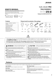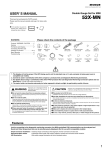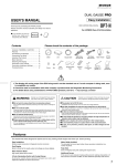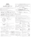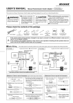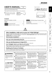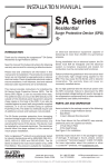
1
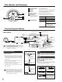
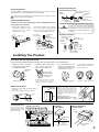
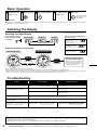
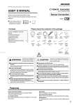
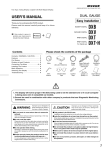
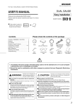
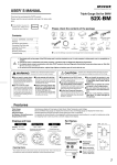
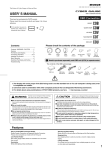
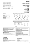
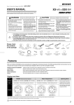
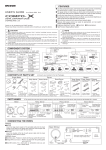
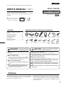
(DSB As of October, 2014 No.5)
One Type Analog Display coupled with Multi-Digital Display.
USER’S MANUAL (
Product Number :
DSB
DUAL GAUGE
)
Sensor Connection
Thank you for purchasing this PIVOT product.
Please read this manual carefully and keep it for future
reference.
● If this produc t is given to
another user, make sure to
include this User’s Manual.
Product
Contents
DSB
+
Please check the contents of the package
Contents / WARNING / CAUTION …… 1
Features ………………………………… 2
Part Names and Displays ……………… 2
Connecting The Wires …………… 2 ~3
Installing The Product…………………… 3
Basic Operation ………………………… 4
Switching The Display ………………… 4
Troubleshooting ………………………… 4
Meter
Unit
Gauge
[50×22× 70(D)mm] Cable
Cut
Connectors
×2
WARNING
BOOST+DIGITAL
T-Joint
Improper use or disregard of
these warnings may result in
the injury or death of people.
●Do not work in areas where there is excessive
exhaust.
Due to vehicle exhaust emission poisoning or fire may
result in a damage to humans.
●Do not crush the cable.
Please be careful that the cable does not get crushed by
the seat rail or car door steel plate, nor cut by any sharp
steel plate as this may cause a poor connection or an
electric short leading to fire or other danger.
●Do not operate while driving.
Operating or checking the display during driving may cause
an accident; please use with the utmost consideration for
safety.
●Please securely fasten the product and be sure
to store bundle away all wires with tape, etc...
It is very dangerous to pull tangled wires by force or allow
tangled wires to interfere with driving.
Nylon Hose
(2m)
Power Cable Adjustable
with fuse 3A
Stand
I-Joint
CAUTION
Conversion
Joint
Allen
Double-sided Cushion
Wrench
Tape × 2
Tape
Rubber
Hose
(5cm)
Zip Ties
User’s
(Large) × 2
Manual
(Small) × 5 (This Book)
Improper use or disregard of these warnings
may c ause injur y to per sons, d amag e the
product and other things.
●This product is for DC12V cars;
Installation cannot be carried out on cars with other voltage batteries.
●Just after installation do not exert any strong force on the product.
When double-sided tape is used for an installation be warned that when hot the
tape temporarily losses adhesiveness.
●Do Not Use Chemical Cleansers.
If the unit gets dirty please wipe with a soft cloth to remove any dirt. Do not use
chemical cleansers such as thinner, benzene, or alcohol.
●Do not install the product in any place subject to high temperature or any place where water may be splashed.
●Make sure to replace all screws and parts to their original place.
●Do not install the product in a place where it will cause distraction.
●Do not, in any manner, process, take apart, or make changes to
this product.
Features
Each of our Dual Gauges offer one type of analog display
coupled with a multi-digital display in one smart looking unit,
thus saving not only space but money.
Wide Range Compatible Sensor Connection Models
Like most gauges, the DS Series models are installed by wiring to
the appropriate sensor; this means greater compatibility with a wide
range of car models.
1
Part Names and Displays
1
1 Analog Display
Display BOOST data.
2 Needle
Shows the current values and peak value.
3 Switch
Use to change modes of digital display
and reset the peak value.
4 Digital Display
Display switches between types.
5 Illumination
Normally illuminated when on display.
(night illumination)
3
2
4
6 Display Range
Analog Display
Dial : White, Needle : Red
Digital Display
Red
Analog Display
BOOST [ -100 〜 200kPa ]
Voltage [ 8 〜 18V ]
Digital Display
Water temp / Oil Temp
[ -35 〜 150°C ]
(Displayed with Sensor
sold separately)
Connecting the Wires
To the inside of the car
BASIC WIRING
To the engine room
Nylon Hose (2m)
Sensor
Hose
I-Joint
Wire harness
grommet, etc.
Backside
of the
meter
(1.5 m)
4-pin
Connector
Unit
5-pin
Connector
2-pin Connector
(Sold separately)
[For water temperature]
( 2.5 m)
(Sold separately)
[For oil temperature]
(1m)
(1m)
2. Stretch the hose that comes out from the
unit but do not pull it off.
② Insert a T-joint and connect the various hoses
and joints as shown in Figure A.
③ Pull the nylon hose to the inside of the car
through a wire harness grommet, etc.
④ Using the I-joint, connect the nylon hose to the
unit. (Figure B)
T-Joint
Red
IGN
Black
Earth
Fuel Regulator,
Charcoal Canister, etc.
Cut the vacuum hose
which can measure
pressure
IGN
Vacuum Hose
(cut)
Red
How to connect
① Cu t t h e va c u u m h o s e w h i c h c a n m e a s ur e
pressure directly from a surge tank or a intake
manifold in the engine room. (e.g.,the hose
c o nne c ting to a fuel reg ulator, a c harc oal
canister, etc.)
Rubber Hose
Surge
Tank
Temperature Sensor
4-pin
Connector
1. Be sure install the unit on the inside of the
car. (Not in the engine room)
Connecting for Boost
Conversion
Joint
Temperature Sensor
( 2.5 m)
Connect to the IGN (12V with key ON)
using the cut connectors (included).
T-Joint
Rubber
Hose
Conversion
Joint
Nylon Hose
Figure A
Nylon Hose
↑To the engine
room
↓To the inside
of the car
Earth
Black
with earth
terminal
Fasten to a screw of a metal
part which is earthed.
●Painted screws and screws connected to plastic
parts are not earthed; make sure to connect
only to a place which is earthed.
【Reference】How to use the Cut Connectors
1
10 mm
2
10 mm
I-Joint
Make sure that all hose and joint connections
are securely fastened so as not to disconnect
or cause pressure loss. (Depending on the
conditions, it may be necessary to take some
action to prevent loosening and disconnection
of the various connection points.)
Hose from
the unit
3
Figure B
4
Unit
Wrap around both
wire coils.
5
Close tightly with cut
connector.
* When crimping, please
Insulate with vinyl
tape.
2
Peel of f of the vinyl
c ove r at t h e e n d of
the product’ s wire.
Peel off of the vinyl
cover at connection.
use crimpers or use
pliers to bend and
then solder together.
Connecting Oil Sensor
Connecting Sensor
Oil Drain Hole Installation
To display Water temperature and Oil temperature, you must purchase
Temperature sensor (DTS ¥3,800) which is sold separately.
Sensor adapter for drain hole
Oil pan
drain hole
(sold separately)
Temperature
sensor
Depending on the installation you may need a sensor adaptor. (sensor
connector 1/8 PT sold separately)
(sold separately)
Standard
drain packing
Connecting Water Sensor
Use the hose joint (sold separately) to attach the temperature sensor
to the upper hose of radiator.
① Cut the upper radiator hose at a
suitable spot.( Water coolant
will spill out, so prepare
replacement coolant.)
Cut
② Fit the hose band onto the cut upper
hose and securely connect the cut
hose to the hose joint with the hose
band, so as no leakage will occur.
Temperature
sensor
Hose joint
Upper hose
(sold separately)
WARNING
White tape
to prevent leakage
1⁄8PT
Fo r c ar s c h a s s i s t h at ar e l ow to t h e
ground or in cases where road conditions
may be poor, please do not use this type
of installation. It may lead the sensor to
bump against the ground and break or be
damaged.
Oil Element Installation
Temperature sensor
White tape
to prevent leakage
(sold separately)
Engine oil
element
connection
1⁄8PT
Radiator
White tape
to prevent leakage
1⁄8PT
Hose band
Oil
element
(sold separately)
Upper hose
Sensor adapter
(sold separately)
Installing The Product
Installation with the Adjustable Stand
Fasten using the double-sided tape. (On top of the steering column cover or dashboard.)
① Slightly loosen the Hexagonal
② Fasten using the double-sided
③ After deciding the position
bolt and install the gauge into
the Adjustable Stand.
t a p e . (C l e a n t h e s u r f a c e;
removing all oil and dust.)
and angle of the meter face,
fasten the Hexagonal bolt
on both sides to secure.
Adjustable
Stand
*It is possible to install the
Ad j u s t a b l e S t a n d i n t h e
reverse direction.
Double-sided
tape (Included)
Clean to remove
oil and dust
be sure about where you wish
*Please
t o i n s t a l l t h e m e t e r, a s i t i s n o t
Hexagonal bolt
Mount into the Panel
Meter Dimensions
① Wrap the cushion tape around the base of
the meter.
② Press into the 60 mm hole in the panel.
Cushion
tape
Installing The Unit
As shown in the right
diagram , fasten the unit
into positions not usually
affected by water.
Hexagonal bolt
advisable to reuse double-sided tape.
(unit; mm)
15 30
Panel
ø60
(Example of Installation)
Under the steering
column cover
On the back side
of the under cover
On the inside of
the driver’s door
wish to fasten the unit to the
* IfA -you
p i l l a r o r c o l u m n c o v e r, p l e a s e
(Reverse direction)
A pillar
purchase and use the separately sold
meter holder which gives you
installation a clean natural look. (For
mounting to the A-pillar or other
slanted surface, it is necessary to use
screws.)
Mater Hood 60 (for ø60)
MH6-U (Multi-Purpose Type) ¥2,980
MH6-C (Processing Kit)
¥2,980
Fastening
to Flat Space
Meter hood
When Fastenings to
a Cable or Pipe
Zip tie
(Large)
Unit
Double-sided
tape
(Included)
Do not install into low positions
(Normal)
Clean to
remove
oil and dust.
Through
holes
Thick cable
or pipe
3
Basic Operation
1
Key Switch ON
(Engine start)
2
Opening Demo
3
4
Display Each Mode
Key Switch OFF
(Engine stop)
5
Meter OFF
The needle stops
when the key is
turned OFF.
Opening Demo
●When the key is turned ON the needle will move to the extreme left several times for searching position. Then it will move to the maximum value and finally
to reading for current measurement item.
Switching The Display
*1. Not displayed without temperature sensor.
Switching The Digital Display
Press switch to change
the multi-digital display
in operation
Water Temp*1
Oil Temp*1
Water Temperature / Oil Temperature
Reading the Display
Voltage
-35 〜 -1°C
The first place on the left
shows“ ” (minus).
-
(decimal point is lightning)
0 〜 99°C
The third place from
the left shows “ ” (Celsius).
c
Display and Reset the Peak Value
Real-time Display
100 〜 150°C
Peak Value Display
Press
Switch
Numerical Value Only.
Press
Switch
for 3 Seconds
DUAL GAUGE
(Lighting)
for 3 Seconds
With no operation
5 Seconds
(Blinking)
Reset the Peak Value
Only the peak value on display
will be reset. This will return to
the Real-time Display for the
currently displayed mode.
*Peak readings are reset when the key is turned OFF.
*For Boost, RPM, Water Temperature and Oil Temperature the high will be shown and for Voltage the low will be displayed.
you wish to check the loss of voltage upon operation of the starter, turn the key to the ON position and after the digital display comes on, operate the
*Ifstarter.
However, Red code must be connected to the 12V IGN wire working with the starter operation and the key on.
Troubleshooting
Trouble
Possible Causes
Possible Solutions
Does not work with Engine start.
Poor connection of Gauge cable , Red or Black
wires.
Please reconfirm whether wiring and connections
are correct or not.
The opening demo starts with Engine
start, but the needle does not work.
Poor connection of the vacuum hose.
Please reconfirm whether wiring and connections
are correct or not.
Unable to measure pressure.
Please make sure to connect the hose which can
measure pressure.
Upon starting up, the unit will not start
in the newly changed display.
Because after changing displays, if the car’ s engine is turned off within 6 seconds, the new setting will not be
stored, make sure to wait at least 6 seconds before turning the engine off.
The displayed values are different from
the standard meter.
This product’ s boost meter reads absolute pressure and may differ from a meter using relative pressure.
T h e Te m p e r a t u r e d i s p l ay s d o n o t
change from ---, or do not show the
value with connecting the sensor.
Poor connection of Temperature sensor
breaking of wire.
or
Please reconfirm Temperature sensor and
whether wiring and connections are correct or not.
※Our products have already been recognized as our Industrial Property or are in the process of receiving Industrial Property status.
※We plan in the near future to take all possible legal measures to protect against unfair competition from look-alike products using similar designs,
regulating characteristics, circuitry and circuitry layout.
※We strictly prohibit the unlicensed use of the PIVOT trademark and the unauthorized use of PIVOT User’s Manual.
4
PIVOT CORPORATION 87-3, Shimookada Okada, Matsumoto-shi, Nagano, 390-0313 JAPAN
http://pivotjp.com/