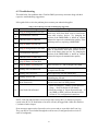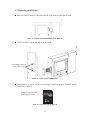
1
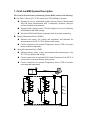
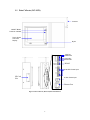
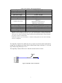
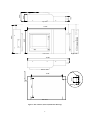
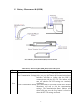
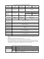
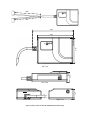
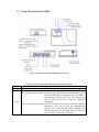
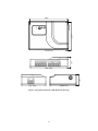
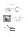
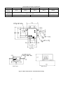
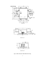
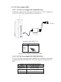
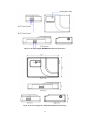
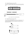
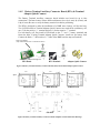
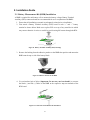
Wireless Battery Monitoring System User Manual Form No. 003-2407 TABLEOFCONTENTS SAFETY INFORMATION ............................................................................................................................................ IV 1. FIRSTLINE BMS SYSTEM DESCRIPTION ............................................................................................................. 1 1‐1 DATA COLLECTOR (DC‐LCD) ............................................................................................................................... 2 1‐2 BATTERY MEASUREMENT KIT (BMK) ................................................................................................................... 5 1‐3 STRING MEASUREMENT KIT (SMK) ..................................................................................................................... 8 1‐4 OTHER ACCESSORIES ....................................................................................................................................... 11 1‐4.1 Optional Hall CT Kit (HCT) ..................................................................................................................... 11 1‐4.2 DC Power Supplies (DPS) ....................................................................................................................... 14 1‐4.3 Optional Temperature Sensor (TES) ...................................................................................................... 16 1‐4.4 Optional Extension Antenna (ANT) ....................................................................................................... 16 1‐4.5 Battery Terminal Auxiliary Connector Board (BTA) & Terminal Adaptor Quick Connect ....................... 17 2. INSTALLATION GUIDE .................................................................................................................................... 18 2‐1 2‐2 2‐3 2‐4 3. BATTERY MEASUREMENT KIT (BMK) INSTALLATION .............................................................................................. 18 STRING MEASUREMENT KIT (SMK) INSTALLATION ................................................................................................ 19 DC POWER SUPPLY (FLU‐BMS‐DPS‐048A) INSTALLATION ................................................................................... 21 DATA COLLECTOR (DC‐LCD) INSTALLATION .......................................................................................................... 22 DATA COLLECTOR (DC‐LCD) OPERATING GUIDE .............................................................................................. 24 3‐1 SCREEN PANEL INTRODUCTION .......................................................................................................................... 24 3‐2 DC‐LCD FUNCTIONS ..................................................................................................................................... 25 3‐2.1 System Status Overview ........................................................................................................................ 25 3‐2.2 Menu ..................................................................................................................................................... 25 3‐2.3 Administrator Mode .............................................................................................................................. 29 3‐2.4 Engineer Mode ...................................................................................................................................... 34 4. SYSTEM CONFIGURATION EXAMPLE .............................................................................................................. 37 4‐1 4‐2 4‐3 4‐4 4‐5 4‐6 4‐7 4‐8 5. KIT INSTALLATION AND CONNECTION .................................................................................................................. 38 TURN ON THE DATA COLLECTOR ......................................................................................................................... 38 ENGINEER LOGIN ............................................................................................................................................ 39 BATTERY SYSTEM STRUCTURE SETUP ................................................................................................................. 40 STRING MEASUREMENT KIT SMK#1 SETUP ......................................................................................................... 41 STRING MEASUREMENT KIT SMK#2 AND SMK #3 SETUP ..................................................................................... 42 BATTERY MEASUREMENT KIT BMK#1~ BMK#16 SETUP ...................................................................................... 43 ADDITIONAL NODE SMK#4 SETUP .................................................................................................................... 44 FIRSTLINE BMS WEB MONITORING GUIDE ..................................................................................................... 46 5‐1 ACCESS THE DC‐LCD USING A WEB BROWSER ....................................................................................................... 46 5‐2 WEB MONITORING PAGE OVERVIEW .................................................................................................................. 46 5‐3 WEB MONITORING FUNCTIONS ......................................................................................................................... 47 5‐3.1 Information and Status ......................................................................................................................... 47 5‐3.2 System Information ............................................................................................................................... 47 5‐3.3 String Information ................................................................................................................................. 48 5‐3.4 Export Report ........................................................................................................................................ 48 5‐3.5 Yearly Report ......................................................................................................................................... 49 5‐3.6 Monthly Report ..................................................................................................................................... 50 5‐3.7 Daily Report .......................................................................................................................................... 51 6. ALARM MESSAGES AND TROUBLESHOOTING ................................................................................................ 52 6‐1 6‐2 6‐3 ALARM MESSAGES .......................................................................................................................................... 52 TROUBLESHOOTING ......................................................................................................................................... 53 REPLACING THE SD CARD ................................................................................................................................. 54 ii Foreword This manual provides the functional descriptions of the hardware and software of the FirstLine Wireless Battery Monitoring System (BMS) and provides instructions to correctly operate the system. General troubleshooting guides are also included. If a problem persists and is not listed in this manual please notify Staco Energy Products Co. immediately. The installation, operation, and maintenance of the system must be carried out only by authorized trained personnel. If not, any injury sustained is not the responsibility of Staco Energy Products Co. iii Safety Information This Safety Information section contains important instructions that must be followed during installation and operation of the FirstLine Wireless Battery Monitoring System (BMS). 1. Installation, operation, and maintenance of the BMS must be carried out only by qualified, authorized trained personnel. 2. Avoid installing the BMS in a hazardous environment. 3. Safety instructions and precautions provided by storage battery and DC equipment manufacturers should be strictly followed when this equipment is used together with the BMS. 4. Do not attempt to service or modify the BMS. Doing so could present the risk of electric shock or other hazard. This device complies with the IEC/EN61010-1 standard in accordance with the Low Voltage Directive (2006/95/EC) and is authorized to use the CE marking. This device complies with the UL 61010-1 standard and is authorized to use the UL marking. This device complies with NCC Rules and is authorized to use the NCC marking. CCAB10LP0520T3 This device complies with Part 15 of the FCC Rules. Operation is subject to the following two conditions. 1. This device must not cause harmful interference. 2. This device must accept any interference received, including interference that may cause undesired operation. FCC ID:X5PRFAN4 Replacement parts must meet the original equipment specifications. Follow replacement instructions to ensure safe electrical isolation. iv 1. FirstLine BMS System Description The FirstLine Wireless Battery Monitoring System (BMS) consists of the following: One Data Collector (DC-LCD) required per UPS and Battery System. Designed to receive transmitted signals from the Battery Measurement Kits and String Measurement Kits. Continuously monitors, analyzes, and stores battery measurements. Equipped with a touch-screen LCD color display for access to all battery measurements and BMS settings. Provides RS-485 and Ethernet communication for remote monitoring. Battery Measurement Kit(s) (BMK) Measures the battery cell voltage and impedance and transmits the measurement to the DC-LCD for analysis and storage. Can be connected to an optional Temperature Sensor (TES) to measure battery terminal temperature. String Measurement Kit(s) (SMK) Measures battery string voltage and transmits the measurement to the DC-LCD for analysis and storage. Can be connected to an optional Hall Current Transformer Kit (HCT) of various ratios to measure battery string current. Can be connected to an optional Temperature Sensor (TES) to measure environmental temperature. Figure 1. FirstLine Wireless Battery Monitoring System Configuration 1 1-1 Data Collector (DC-LCD) Antenna ON/OFF Button Power On Indicator Touch Screen LCD Color Display Stylus Input Dry Contact Port Output Dry Contact Port RS-485 35-60 VDC Power Input SD Card Slot 12 VDC Power Input Ethernet Port Figure 2. Data Collector (DC-LCD) External Features 2 Table 1. Data Collector (DC-LCD) Specifications Model Operating Temperature Relative Humidity Input Power Supply Power Consumption Receiving Interface Communication Ports Monitoring Nodes Display Type Storage Media Dimensions (H x W x D) Weight FLU-BMS-DC-LCD 0-40°C / 32-104°F ≤ 95% 12 VDC / 48 VDC Maximum 12 W RF 2.4 GHz for wireless1 Ethernet x 1 RS-485 x 1 Output Dry Contact Port x 1 Input Dry Contact Port x 1 Maximum 256 nodes per system LCD 6.4″ Graphic Touch Screen 2 Gigabyte SD/MMC Flash Memory Card2 9.8” x 14.9″ x 3.2″ 6.6 lbs 1 Maximum receiving distance is rated at 164 ft. in a non-enclosed room or cabinet. Recommended distance is 98 ft. for optimal performance. The layout of the installation environment, shelter and other factors can weaken transmitting signal and shorten the transmitting distance, thereby affecting the quality of wireless communications. 2 Continuous storage for up to 40 months at a 5-minute recording interval for 256 nodes. Recording interval is configurable. The Input Dry Contact Port enables the user to connect an external switch with which to change the recording interval time. Refer to Data Record Setup in Section 3-2.3.4.2 and Dry Contact Setup in Section 3-2.3.8. The Input Dry Contact will be active when the external switch is closed. Switch Figure 3. Input Dry Contact Connections 3 1.85” 2.49” 3.20” Top View 8.05” 9.83” 15.53” Left View Front View Right view 14.88” Bottom View ɸ0.28 0.49” 11.28” 6.61 “ ɸ0.37 Rear View Figure 4. Data Collector (DC-LCD) Dimension Drawings 4 1-2 Battery Measurement Kit (BMK) Figure 5. Battery Measurement Kit (BMK) External Features Table 2. Battery Measurement Kit (BMK) Button Function Description Button Reset Setup Function Description Press this button to reset the BMK when it is not working properly. This button sets and clears the communication settings in the DC-LCD. Set Communication Settings: After you press this button the Communication Status Indicator will flash to indicate that the BMK is communicating with the DC-LCD. The indicator will turn off when the DC-LCD settings are completely configured. Clear Communication Settings: Press this button for 4 seconds (or until Error Indicator illuminates solid red) to clear the communication settings. The Communication Status Indicator will shine solid green once the Setup button is released to show the DC-LCD settings are cleared. 5 Table 3. Battery Measurement Kit (BMK) Specifications Model Cell Voltage Cell Voltage Measurement Range Accuracy Battery Impedance Resolution Cutoff Voltage1 Start Up Voltage2 Temperature Measurement Range3 Accuracy Operating Temperature Humidity Power Consumption Input Impedance Transmitting Interface4 Sampling Rate Dimensions (H x W x D) Weight FLU-BMS-BMK- FLU-BMS-BMK- FLU-BMS-BMK- FLU-BMS-BMK002A 006A 012A 012B 2V 6V 12 V 1.48-4.00 V 4.2-8.0 V 8.5-16.0 V ±10 mV > 65 Ah < 65 Ah 0.03 mΩ 0.10 mΩ 0.01 mΩ 0.03 mΩ 1.48-1.55 V (Default 1.5 V) 4.2-4.5 V (Default 4.5 V) 8.5-9.3 V (Default 9.0 V) 1.65 V 4.8 V 9.6 V 0-100C / 32-212F ±1C / 1.8F 0-50C / 32-122F ≤ 95% ≤ 0.5 W 1 MΩ RF 2.4 GHz Wireless 1 Hz (1-second sampling interval) 1.1” x 3.9″ x 2.8″ 3.4 oz 1 When the battery voltage is too low the BMK will automatically stop working to avoid draining the battery during a charger failure or power outage. The cutoff voltage can be configured. Refer to Section 3-2.4.7 of this manual. 2 The BMK cannot start up when the battery voltage is too low. 3 An optional Temperature Sensor is required to measure battery terminal temperature. 4 Maximum transmitting distance is rated at 164 ft. in a non-enclosed room or cabinet. Recommended distance is 98 ft. for optimal performance. The layout of the installation environment, shelter and other factors can weaken transmitting signal and shorten the transmitting distance, thereby affecting the quality of wireless communications. An external antenna is recommended (see Section 1-4.4 of this manual). Table 4. Battery Measurement Kit (BMK) LED Indicators Description Indicator Error (Red) Communication Status (Green) Status Description On This BMK is abnormal. On This BMK has not yet configured its communication settings. Flashing This BMK is transmitting data or communication settings. This BMK’s communication settings have been configured, and Off now there is no data transfer. 6 9.84” 9.84” 4.45” 2.75” 3.94” 1.07” Top View 1.07” Side View Left View Right View Figure 6. Battery Measurement Kit (BMK) Dimension Drawings 7 1-3 String Measurement Kit (SMK) Figure 7. String Measurement Kit (SMK) External Features Table 5. String Measurement Kit (SMK) Button Function Description Button Reset Setup Function Description Press this button to reset the SMK when it is not working properly. This button sets and clears the communication settings in the DC-LCD. Set Communication Settings: After you press this button the Communication Status Indicator will flash to indicate that the SMK is communicating with the DC-LCD. The indicator will turn off when the DC-LCD settings are completely configured. Clear Communication Settings: Press this button for 4 seconds (or until Error Indicator illuminates solid red) to clear the communication settings. The Communication Status Indicator will shine solid green once the Setup button is released to show the DC-LCD settings are cleared. 8 Table 6. String Measurement Kit (SMK) Specifications FLU-BMS-SMK-0750 0-750 VDC Model Voltage Measurement Range Normal Voltage Range Accuracy Current Measurement Range1 Accuracy Temperature Measurement Range2 Accuracy Operating Temperature Humidity 20-750 VDC ±0.2% of normal voltage 0-3000 A ±3% 0-100C / 32-212F ±1C / 1.8F 0-50C / 32-122F ≤ 95% 35-60 VDC Maximum 3 W Input Power Supply Range Power Consumption Input Impedance Transmitting Interface 3 Sample Rate Dimensions (H x W x D) Weight 1 MΩ RF 2.4 GHz Wireless 1 Hz 1.1” x 3.9″ x 2.8″ 3.1 oz 1 An optional Hall CT Kit (HCT) is required to measure battery string current. An optional Temperature Sensor (TES) is required to measure environmental temperature. 3 Maximum transmitting distance is rated at 164 ft. in a non-enclosed room or cabinet. Recommended distance is 98 ft. for optimal performance. The layout of the installation environment, shelter and other factors can weaken transmitting signal and shorten the transmitting distance, thereby affecting the quality of wireless communications. An external antenna (ANT) is recommended (see Section 1-4.4 of this manual). 2 Table 7. String Measure Kit (SMK) LED Indicators Description Indicator Error (Red) Communication Status (Green) Status Description On This SMK is abnormal. On This SMK has not yet configured its communication settings. Flashing This SMK is transmitting data or communication settings. This SMK’s communication settings have been configured, and Off now there is no data transfer. 9 2.75” 3.94” 1.07” Front View 1.07” Side View Left View Right View Figure 8. String Measurement Kit (SMK) Dimension Drawings 10 1-4 Other Accessories 1-4.1 Optional Hall CT Kit (HCT) BMS-HCT 50 ~ 600A Figure 9. Hall CT Kit (HCT) 50 ~ 600A External Features BMS-HCT 2000A Figure 10. Hall CT Kit (HCT) 2000A External Features Input Voltage LED Input Voltage Input Voltage Input Voltage LED Input Voltage Output Signal Figure 11. Hall CT Kit (HCT) Signal Connection Terminal Block 11 Table 8. Hall CT Kit (HCT) Specifications FLU-BMS-HCT-005 FLU-BMS-HCT-010 FLU-BMS-HCT-030 FLU-BMS-HCT-060 FLU-BMS-HCT-200 Model Hall CT 50 A 100 A 300 A 600 A 2000 A Ratings Dimensions 3.4” x 7.6″ x 9.0″ (HxWxD) 2.2” x 7.6″ x 5.0″ Weight 1.4 lbs 1.8 lbs 11.0 lbs Note: To be used with an SMK. Top view 1 2 3 4 LED B LED A Side View 1 Side View 2 Figure 12. Hall CT Kit (HCT) 50 ~ 600A Dimension Drawings 12 INPUT 1 : +18V 3 : Output 2 : -18V 4 : 0V 12 3 4 LED A : +15V LED B : -15V Top View Side View 1 Side View 2 Figure 13. Hall CT Kit (HCT) 2000A Dimension Drawings 13 1-4.2 DC Power Supplies (DPS) 1-4.2.1 12 V DC Power Supply (FLU-BMS-DPS-012A) The DC Power Supply converts single-phase 120VAC power to 12 V DC to supply power to a DC-LCD. One (1) power supply required for each DC-LCD. AC Input 12 V DC Power Supply Input Power Plug NEMA 5-15P . Model FLU-BMS-DPS-012A USA Power Plug Figure 14. DC Power Supply FLU-BMS-DPS-012A Features 1-4.2.2 48 V DC Power Supply (FLP-BMS-DPS-048A) The DC Power Supply converts single-phase 120VAC power to 48 V DC to supply power to a String Measurement Kit (SMK). One (1) DC power supply kit can supply up to five SMKs. Table 9. DC Power Supply DPS-048A Specifications Model Input Power Output Power Dimensions (H x W x D) Weight FLU-BMS-DPS-048A 120VAC 50/60 Hz 48 VDC, 15 watts 1.1” x 3.9″ x 2.8″ 5.3 oz 14 Figure 15. DC Power Supply FLU-BMS-DPS-048A External Features Figure 16. DC Power Supply FLU-BMS-DPS-048A Dimension Drawings 15 1-4.3 Optional Temperature Sensor (TES) The TES can be connected to a BMK or SMK to measure individual battery cell terminal temperature or environmental temperature. Electrical tape may be used to hold the TES in place. Table 10. Temperature Sensor Specifications Model Measurement Range Length FLU-BMS-TES 0-100C / 32-212F 118” 118” .17” .28” Figure 17. Temperature Sensor (TES) Dimension Drawing 1-4.4 Optional Extension Antenna (ANT) The extension antenna (RECOMMENDED) can be attached to a BMK or SMK to increase the wireless signal strength and enhance performance; however, the addition of this extension antenna DOES NOT increase the transmitting-receiving distance between the BMK, SMK, and DC-LCD. 90 o o 135 3.44” 4.33” Figure 18. Antenna Dimension Drawing 16 1-4.5 Battery Terminal Auxiliary Connector Board (BTA) & Terminal Adaptor Quick Connect The Battery Terminal Auxiliary connector board includes one board for up to four connections. The board comes in three different diameter sizes: 6 (6 mm), 8 (8 mm), and 10 (10 mm). Be sure to verify the battery terminal size before purchasing. The BTA is designed to make the installation of a BMK onto a battery cell fast and easy. Two (2) BTA boards or Terminal Adaptor Quick Connects are required for each battery cell, one (1) for the positive “+” terminal and one (1) for the negative “-” terminal. For each battery cell, first install a BTA board on the “+” and “-” battery terminals and fasten the bolts. If using Terminal Adaptor Quick Connects, install one per battery lead. Connect the black “-” cable and red “+” cable of the BMK onto the snap-on terminals. Snap-on terminals (Any terminal from CN1 to CN4 can be used.) Affix battery terminal through here. BTA Board BTA Terminal Adaptor Quick Connect Figure 19. Battery Terminal Auxiliary Connector Board (BTA) and Terminal Adaptor Quick Connect 1.77” ɸ0.24 1.77” ɸ0.32 ɸ0.39 1.18” 1.18” 1.18” BMS-BTA-06 1.77” BMS-BTA-08 BMS-BTA-10 676-0091 Figure 20. Battery Terminal Auxiliary Connector Board and Quick Connect Dimension Drawings 17 2. Installation Guide 2-1 Battery Measurement Kit (BMK) Installation A BMK is required for each battery cell to measure the battery voltage. Battery Terminal Auxiliary (BTA) connector boards are recommended for use in conjunction with BMKs. 1. Ensure that all installation personnel are adequately trained prior to installation. 2. First attach a Battery Terminal Auxiliary (BTA) board to each “+” and “-” battery terminal as shown below. Make sure to place BTA over top of any metal device which may connect batteries in series or parallel to avoid passing full current through the BTA. Figure 21. Battery Terminal Auxiliary (BTA) Drawings 3. Remove the backing from the adhesive patches on the BMK then position and mount the BMK onto the top or side of the battery block. Figure 22. Adhesive Patches on the BMK 4. Use an insulated pair of pliers (Important: Do not use your bare hands!) to connect the black (-) and red (+) cables of the BMK to the respective snap-on terminals of the BTA board. Figure 23. Connection of the BMK to the BTA Board 18 5. The following figure shows a completed BMK setup using two BTA boards. A green LED will shine if the BMK is correctly connected to the battery terminals. If the LED does not shine press the Setup button for 4 seconds to clear the setting and make the green LED shine. Figure 24. Complete BMK Setup 6. Attach the optional Temperature Sensor (TES) (if purchased) to the BMK if you wish to measure the battery temperature. Figure 25. Temperature Sensor Attachment Location 2-2 String Measurement Kit (SMK) Installation A SMK can be installed at the DC bus terminals to measure total system voltage and current. Also, an SMK can be installed on each individual battery string to measure the battery string voltage and current. Please note that an optional Hall Current Transformer (HCT) with correct current ratio must be installed with each SMK for total current or string current measurement. For details on Hall Current Transformers, contact Staco Energy Products Co. 19 SMK #1 DPS-048A SMK #5 SMK #2 SMK #3 ……………… Figure 26. String Measurement Kit Assembly SMK Installation Steps: 1. Remove the backing from the adhesive patches on the SMK, then position and mount the SMK securely onto the Hall Current Transformer (HCT) if purchased, or the equipment (e.g. UPS). Use a cable tie for more secure mounting if necessary. 2. Organize the necessary measuring cables and terminate each of the loose cable ends in a terminal block for easy connection to the SMK sockets. 3. Plug the terminal blocks into the SMK as illustrated below. Figure 27. SMK Connection Assembly 4. Connect the SMK wires to the appropriate positive and negative battery string terminals on the BTAs. 20 Figure 28. Connection of the SMK to the BTA Board 5. A green LED will illuminate if the SMK is correctly connected to the battery terminals. If the LED does not illuminate press the Setup button for 4 seconds to clear the setting and make the green LED illuminate. Figure 29. Location of the LED indicator Light 2-3 DC Power Supply (FLU-BMS-DPS-048A) Installation FLU-BMS-DPS-048A Installation Steps: 1. Remove the backing from the adhesive patches on the FLU-BMS-DPS-048A then mount it securely in the desired position. Use a cable tie for more secure mounting if necessary. 2. Terminate the 48 VDC output cable and AC power input cable in terminal blocks for easy connection to the FLU-BMS-DPS-048A sockets. 3. Connect the cables to the FLU-BMS-DPS-048A as illustrated in the following figure: 21 48 VDC Output _ + _ AC Power Input + L Positive Terminal Negative Terminal N AC Power Input (L) AC Power Input (N) Positive Terminal Negative Terminal Figure 30. Connection Assembly of the FLU-BMS-DPS-048A 2-4 Data Collector (DC-LCD) Installation The Data Collector (DC-LCD) receives the measurement signals from the BMKs and SMKs wirelessly. The measurement data is displayed graphically on the color LCD touch-screen panel. The data is compressed and stored in a 2 GB SD card FirstLine BMS system configuration and controls are also performed using the DC-LCD. Data Collector Installation Steps: 1. Attach the antenna to the DC-LCD as illustrated below. Figure 31. Location of Antenna Placement on the DC-LCD 2. Mount the DC-LCD on a wall or battery cabinet using the mounting holes on the back of the DC-LCD. 22 0.49” ɸ0.28 ɸ0.37 Figure 32. Data Collector Mounting Holes 3. The DC-LCD has two power input options: 48 VDC and 12 VDC. Select the one that is available on site and most suitable to your application. Figure 33. Location of Input Sources on the DC-LCD 4. Push the ON/OFF button to turn on the DC-LCD. Figure 34. Location of the ON/OFF Button on the DC-LCD 23 3. Data Collector (DC-LCD) Operating Guide The DC-LCD panel is a touch-screen device. To operate the touch-screen panel please use the stylus provided. Drag across the screen to navigate. Tap on the screen to enter information. 3-1 Screen Panel Introduction The DC-LCD screen panel is divided into three fields: “Page Selection”, “System Information” and “Operation” as illustrated below: System Information Icons: Total Nodes Return to System Status. Total Connected Nodes Storage capacity of the SD card Return to Previous Page. Year/Month/Day Hours : Minutes : Seconds 24 3-2 DC-LCD Functions 3-2.1 System Status Overview Displays occurring events. Click on a displayed event to view real-time battery measurement charts. Provides a system status overview. 3-2.2 Menu For selecting functions. 3-2.2.1 Event Log Go to the “Menu” page and click [Event Log]. The event log can be viewed by year, month, or day. Select [Year] and use the arrow keys to select the desired year. The newest 1,000 logs of the desired year will be shown. Select [Month] and use the arrow keys to select the desired month. The newest 1,000 logs of the desired month will be shown. Select [Day] and use the arrow keys to select the desired day. The newest 1,000 logs of the desired day will be shown. When viewing the event log, logged data will not automatically update. To allow the event log to successfully update, back out to the “Menu” page and then re-enter the Event Log. 25 3-2.2.2 Language Click「Language」to select the language used on the LCD display of the DC-LCD. 3-2.2.3 Battery Charge/Discharge Recording and Viewing 3-2.2.3.1 Recording Enables the user to record battery performance during a system charge and discharge test. Procedure: 1. Click “Battery Charge/Discharge Recording and Viewing” on the “Menu” page. In the “Recording” panel select the desired system (e.g. UPS System 1), and click [Start Record]. 2. Command the UPS to perform a battery charge/discharge test according to the UPS operating instructions. 3. Once the UPS starts its charge/discharge test, a “Data Recording” dialogue box will pop up on the Data Collector screen. Click [Stop Record] to stop the recording. 4. You can type remarks pertaining to this test in the “Memo” box (up to 16,000 characters). Click "OK" to save the test records. 26 3-2.2.3.2 Viewing Enables the user to review recorded battery performance during past and present system charge and discharge tests. Procedure: 1. Go to the “Battery Charge/Discharge Recording and Viewing” page. In the “Viewing” panel select the desired historical data from the “View Type” box. 2. There are four selections in “View Type”: (i) Battery: Individual battery cells (ii) Batteries in a String: All batteries connected to a particular string (iii) String: Individual battery strings (iv) Stings in a System: All battery strings connected to a particular system 3. 3. Click [View Record] to display the data. 3-2.2.4 Real-Time Monitor 3-2.2.4.1 System Select Page Displays the voltage and current (and ambient temperature if a TES is installed) of each connected system. 3-2.2.4.2 String Select Page Displays the voltage and current (and ambient temperature if a TES is installed) of each connected battery string. 27 3-2.2.4.3 Block Table Click [Detail] on the [String] icon to view its Real-time Curve. Displays the voltage and impedance (and battery cell temperature if a TES is installed) of individual connected battery cells. Click on an individual [NODE] icon to display the battery cell table of that particular string. Values will appear in different colors depending on the status of the battery cell. Black is normal, red is too high, blue is too low, and gray indicates that the measure kit link has failed. 3-2.2.4.4 Bar Graph Displays a bar graph of either the voltage or the impedance of all of the connected batteries in that particular battery string. Click on an individual bar to display the information box of that particular battery cell. Click this information box to display the real-time chart of that particular battery block. Click this information box to display the real-time chart. 3-2.2.4.5 Percentage Displays a bar chart of the average percentage readings of either voltage or impedance of all the connected batteries in that particular battery string. Click on an individual bar to display the information box of that particular battery cell. Click this information box to display the real-time chart of that particular battery cell. 28 Click this information box to display the real time curve 3-2.2.4.6 Real-time Curve Displays a line chart of the voltage and impedance (and temperature if a TES is installed) of a particular battery cell for the most recent 180 seconds. Click on any part of the curve to display the historical chart for that particular battery cell. 3-2.2.4.7 Historical Curve Provides individual battery block historical measurement data. Click [Real-Time Curve] to return to the real-time measurement chart. Click [Start Time] to set the start time of the history chart. Drag the data line to change the starting time of the measurement. 3-2.3 Administrator Mode 3-2.3.1 Administrator Login Initially log in by clicking [Administrator Login] and entering the default password “1234”. Upon successful log in, the [Setup] and [Administrator Password Change] icons will appear on the “Menu” page as shown below. Click [Administrator Logout] to log out. 29 3-2.3.2 Administrator Password Change To change the password, enter the default password “1234” and you will be prompted to enter a new password. The password should be between 4 to 12 numeric digits. 3-2.3.3 Data Collector Setup The [Setup] menu provides options to configure the Battery Monitoring System. The [Setup] button will appear on the “Menu” page only after successful Administrator Login. Click on [Setup] to open the setup menu page as shown below. 3-2.3.4 Alarm Conditions and Data Recording Setup 3-2.3.4.1 Alarm Conditions Enables the user to set the conditions which trigger or turn off alarms in the system. Alarms will appear on the System Status Overview screen and will be recorded in the Event Log. The settable parameters are: System System voltage Total current (+/- indicates direction of current) (only if a Hall CT is installed) Temperature (only if a TES is connected) Battery String String voltage String current (+/- indicates direction of current) (only if a Hall CT is installed) Temperature (only if a TES is connected) Battery (block) Battery Voltage Impedance Temperature (only if a TES is connected) Users may select which alarms appear on the System Overview screen and in the Event Log by checking or unchecking the boxes next to the heading titles. See figure below. All “High” and “Low” level 2 values trigger the alarms. All “High” and “Low” level 1 values turn off the alarms. 30 Users may choose to receive notification of these alarms via email and/or view them through a web browser. See Section 3-2.3.5 for information on setting up these functions. For a complete list of errors, refer to Section 6 Alarm Messages and Troubleshooting. 3-2.3.4.2 Data Recording Enables the user to select the type of recording and set the recording periods and conditions. FIFO: The DC-LCD will discard old data to make room for new data in first-in-first-out order if this function is selected. Otherwise, new data will be recorded until the storage space is full and, after that, recording will stop. Enable Recording: The DC-LCD will record all battery data continuously if this function is selected. The sampling interval can be set from 1 second to 60 minutes. Intelligent Recording Mode: The Intelligent Recording sampling interval can be set from 1 second to 60 minutes. Starts recording only upon the following conditions. System voltage exceeds the set value. System voltage drops below the set value. System current exceeds the set value. System current drops below the set value. String voltage exceeds the set value. String voltage drops below the set value. String current exceeds the set value. String current drops below the set value. The Maximum Intelligent Recording Time can be set from 1 minute to 60 hours. 31 After performing Intelligent Recording for more than this maximum time, the DC-LCD will stop the Intelligent Recording mode automatically. In order to conserve data storage capacity and collect just the necessary battery measurements, the user can use this function to set a shorter sampling interval during charge and discharge periods and a longer sampling interval during normal use (“float charge” periods). 3-2.3.5 Network and E-mail Setup This page allows the user to set up the Internet and web server parameters for the DC-LCD as well as to enable alarm alerts via E-mail. Please restart the DC-LCD to ensure that the new settings take effect. Consult your IT professional if necessary to ensure proper settings are applied and to verify that no issues with any web or email filtering will occur on your network. Internet parameters E-mail settings Web server port 3-2.3.6 System Time Setup Enables the user to set the current date and time of the DC-LCD. 32 3-2.3.7 Impedance pu Setup The DC-LCD expresses battery impedance in the form of pu values, which provide a simple way to observe the change of impedance in a battery block. The definition of pu value is as follows. Battery impendance pu Battery impendance base The Impedance pu Setup page enables users to set the battery block impedance base value. There are three types of setting: Select「Automatically set impedance base when battery voltage is over xx V」: When the battery cell voltage first reaches the preset value, the impedance value measured by the BMK at that time shall become its base value. We recommend using the floating charge voltage of a battery cell as the voltage value. 「All batteries’ base is xx mΩ」: Use xx mΩ as the impedance base for all batteries in this system. Click「Set」to activate the setting. We recommend using the factory default impedance value as the base value. Contact the battery manufacturer to get the default impedance value. 「Use the current time value as the impedance base.」: Click this icon to activate the setting. We recommend using this setting when the batteries are in their normal “floating charge” state. Click「Clear all batteries’ impedance base.」to clear the impedance base. The DC-LCD will no longer express impedance as a pu value, but will continue to express impedance in mΩ. 3-2.3.8 Dry Contact Setup This page enables the user to set the Input and Output Dry Contacts. Input Dry Contact. There are two settings: None: No action regardless of whether the input dry contact switch is in the open or closed position. Intelligent Recording: Intelligent Recording is enabled when the input dry contact switch is in the closed position and disabled when the switch is in the open position. 33 Output Dry Contact. There are two settings: Intelligent Recording: Refer to Section 3-2.3.4.2 to select Intelligent Recording. Measure Value Out of Range: Refer to Section 3-2.3.4.1 to set alarm conditions. 3-2.3.9 Data Collector Setup Temperature Unit: Select whether to display temperature in degrees Celsius or degrees Fahrenheit. RS-485 Baud Rate: Set the communication speed for RS-485 communication. The speed range is from 2400 to 115200. Data Collector ID: Set unique identification numbers for each DC-LCD when using RS-485 communication for remote monitoring. The range of ID numbers is from 1 to 255. 3-2.4 Engineer Mode The following sections detail functions which are unique to Engineer Mode. Engineer Mode contains all functions required to set up a system and also includes all menus and functions found in Administration Mode. 3-2.4.1 Engineer Login Log in by clicking [Administrator Login] and entering the default engineer password “87654321”. Upon successful log in the [Setup] and [Engineer Password Change] icons will appear on the [Menu] page as shown below. Click [Engineer Mode Logout] to log out. 34 3-2.4.2 Engineer Password Change To change the password, enter the existing password and you will be prompted to enter a new password. Passwords should comprise 4 to 12 numeric digits. 3-2.4.3 Engineer Mode Menu The [Setup] menu provides configuration options for the Battery Monitoring System. The [Setup] icon will appear on the [Menu] page only after successful Engineer Login. Click [Setup] to open the setup menu page as shown below. 3-2.4.4 Battery System Structure Setup Enables the user to add a new battery system or remove an existing system. Click on [Battery System Structure Setup] to open the “System Setup” dialogue box as shown below. Define the System Name. The System ID is normally generated automatically without input. However, if two or more DC-LCDs are used within 50 meters of each other, in order to avoid communication interference a unique System ID needs to be manually set for each system. Configure up to 8 battery systems per DC-LCD (7 if additional nodes are required). Configure up to 8 strings per battery system. Configure up to 250 battery cells per string. Configure up to 250 additional nodes per battery system. Configure up to 256 measure kits per DC-LCD. 3-2.4.5 Sensor Network Setup Enables the user to configure each installed SMK, Hall CT, TES, and BMK, including assigning and changing ID numbers. For details regarding adding a new system refer to Section 4 of this manual. 35 3-2.4.6 Connector Test Enables the user to test RF, Dry Contact, and RS485 connections (if any exist). Also shows the Ethernet IP address if one exists. 3-2.4.7 BMK Cutoff Voltage Setup Enables the user to set up the cutoff voltage of a BMK. The BMK will stop working when the battery voltage drops below this value. 3-2.4.8 Enables the user to define the interval between impedance measurements. 3-2.4.9 Impedance Measurement Interval Setup Measure Impedance Immediately Enables the user to measure the battery impedance immediately. 36 4. System Configuration Example Figure 35 illustrates a sample FirstLine BMS system. A backup power system is connected to a battery bank consisting of two strings of batteries, each of which consists of eight battery blocks (12 V, 100 AH). The maximum string current is 40 A. The sample FirstLine BMS system collects the following information. Each battery cell's voltage and impedance Each battery string's voltage and current The backup power system DC bus's voltage and total current Four ambient temperature measurements One SMK and a Hall CT are connected across the UPS DC bus. Another SMK and Hall CT are connected across each battery string. The required FirstLine BMS kits and accessories for this example are shown in the following table. Table 11. FirstLine BMS Sample Kits and Accessories Model Number DC-LCD DPS-12A DPS-48A BMK-12A SMK-0750 HCT-005 HCT-010 TES BTA-08 Description Data Collector 12 V DC Power Supply 48 V DC Power Supply 12 V Battery Measure Kit String Measure Kit 50 A Hall Current Transformer Kit 100 A Hall Current Transformer Kit Temperature Sensor 8ɸ Battery Terminal Auxiliary Connector Board Qty 1 1 1 16 4 2 1 4 32 Notes for 2 strings of 8 batteries Each battery needs two BTA boards. Refer to the sample diagram shown when installing kits and accessories for your own system. The installation and setup procedures are described in the following pages. 37 Figure 35. Sample System Diagram 4-1 Kit Installation and Connection Please refer to Section 2 for installation of all kits and accessories. Ensure that the BMK, SMK, and DC-LCD are situated within a distance of 98 ft. (in an open environment). 4-2 Turn on the Data Collector Press the ON/OFF button to start the DC-LCD. 38 The following will appear on the LCD screen: Click「Menu」 4-3 Engineer Login Click「Administrator Login」 Enter the default engineer password “87654321”. 39 Click「Setup」to enter Engineer Mode. 4-4 Battery System Structure Setup Click「Battery System Structure Setup」 to configure the battery bank. System Setup 1. Click「Add」to add a new battery system (the password will be requested again). 2. Enter a desired System Name (e.g. “UPS System 1”). 3. Enter “2” for [Strings] (2 battery strings in this system). 4. Enter “8” for [Blocks] (8 battery cells in each string). 5. Enter “1” for [Additional Nodes]. (This system needs an additional temperature sensor.) 6. Select「String Measure Installed」to indicate whether or not an SMK is installed on each battery string. 7. Select「System Measure Installed」to indicate whether or not an SMK is installed to measure complete system voltage 8. Click「Update」to finish the setup. 9. Click to return to the Setup Menu. 40 4-5 String Measurement Kit SMK#1 Setup 1. Click「Sensor Network Setup」. 2. Click「Click To Allocate」to set up SMK#1. 3. Select「Temperature」if a TES is installed. Select「Current」 if an HCT is installed, and then choose the CT Ratio. The user can choose 50:1, 100:1, 300:1, 600:1 or 2000:1. This example uses the HCT-010 100A, so we choose 100:1. 4. Click the “Setup” button on SMK#1. The words “Setting Successful” will appear in the dialogue box upon successful setup. 5. SMK#1 will be configured to a unique ID for communication with the DC-LCD. 41 4-6 String Measurement Kit SMK#2 and SMK #3 Setup 1. Click「Setup Strings」on UPS System 1. 2. Click「Click To Allocate」on the desired string. 3. Select「Temperature」if a TES is installed. Select「Current」if an HCT is installed, and then choose the CT Ratio. The user can choose 50:1, 100:1, 300:1, 600:1, or 2000:1. This example uses the HCT-005 50A, so we choose 50:1. 4. Click the “Setup” button on SMK#2. The words “Setting Successful” will appear in the dialogue box upon successful setup. 42 5. Repeat from step 2 to set up SMK#3. SMK#2 and SMK#3 will be configured to a unique ID for communication with the DC-LCD as shown below. 4-7 Battery Measurement Kit BMK#1~ BMK#16 Setup 1. Click「Setup Blocks」on the desired string. 2. Click「Not Allocated」on the desired battery block. 3. Select「Temperature」if a TES is installed. 43 4. Click the “Setup” button on the BMK to be configured. The words “Setting Successful” will appear in the dialogue box upon successful setup. 5. Repeat from step 2 to set up the other BMKs in this string. Repeat from step 1 to set up the other string. Each BMK will be configured to a unique ID for communication with the DC-LCD as shown below. 4-8 Additional Node SMK#4 Setup 1. Click to return the String Select screen of UPS System 1. Click「Additional Node」. 2. Click「Not Allocated」on NODE 1. 44 3. Select「Temperature」. 4. Click the “Setup” button on SMK#4. The words “Setting Successful” will appear in the dialogue box upon successful setup. 5. SMK#4 will be configured to a unique ID for communication with the DC-LCD as shown below. Important Note: If any of the following messages appears in the dialogue box during SMK or BMK setup: "Scan Antenna Timeout", "Getting Calibrate Value Fail", "Setting Fail", or "Setting Fail (Timeout)", please press and hold the Setup button on the SMK or BMK to reset the device and try again. If the problem persists please contact your authorized dealer. 45 5. FirstLine BMS Web Monitoring Guide The FirstLine BMS Data Collector comes with a built-in web server. Through various network devices (e.g. a computer) connected to the same Ethernet network as the DC-LCD via its RJ45 port, this function allows the user to monitor real-time information and download reports from the DC-LCD using a web browser. Note that this works only on the same local area network as the DC-LCD. To access the DC-LCD from a remote location, consult your network administrator. 5-1 Access the DC-LCD using a web browser The procedure to access the Data Collector web server using a computer web browser (e.g. Internet Explorer) is as follows: 1. On the Data Collector [Setup] page click [Network and E-mail Setup]. 2. On the [Network and E-mail Setup] page as shown below, verify the IP Address and Port. The URL to enter in the computer web browser shall be as such: http://192.168.1.123:1234. 3. You can now access the DC-LCD from the web browser after entering the URL. 5-2 Web Monitoring Page Overview Once the DC-LCD has been successfully accessed using the web browser, the web monitoring page of the DC-LCD appears as shown below. The page is divided into two areas: "Browsing Toolbar" and "Information and Functions" as shown below: Figure 36. Web Monitoring Page Overview Click [Home] to return to the main menu. Click [Back] to return to the previous page. 46 5-3 Web Monitoring Functions 5-3.1 Information and Status This page displays the list of systems connected to the DC-LCD, a summary of the recorded events, and the real-time display of system parameters. In the “System Name” column, click on a system to see its connected battery string information. Click “Download Event log(.cvs)” to download the Event Log list. Figure 37. Connected Systems Information and Status 5-3.2 System Information This page displays the list of battery strings. The display shows the real-time readings of the battery string parameters. Select a string to see its information for each connected battery. Click [Export Report] to view the report on the particular string. See [Export Report] on the following page for more details. Figure 38. Individual System Information 47 5-3.3 String Information This page displays the list of battery cells in the string and displays real-time readings of each battery block’s voltage, impedance, and temperature. Figure 39. String Information 5-3.4 Export Report When you select [Export Report] on the “System Information” page the following page will appear. Select the type of report to export by clicking [Yearly Report], [Monthly Report], or [Daily Report]. Figure 40. String Export Report Page 48 5-3.5 Yearly Report This page displays the annual data for the selected string of the selected system. The report shows the average readings (cell voltage, impedance, and temperature) of individual battery cells over a twelve-month period of the selected year. Red text indicates that the reading exceeds the preset value, and blue text indicates that the reading is below the preset value. Click “Show Chart” for any cell to display that battery cell’s chart. Move the mouse pointer to any point on the data line to display the recorded value at that point in time. At the top right-hand corner of the screen click “Export csv file” to export the data into CSV (Comma Separated Values) format for data processing. Figure 41. Yearly Report Graphical Display 49 5-3.6 Monthly Report This page displays the monthly data for the selected system. The report shows the average readings (cell voltage, impedance, and temperature) of individual battery cells over a thirty-day period of the selected month. Red text indicates that the reading exceeds the preset value, and blue text indicates that the reading is below the preset value. Click “Show Chart” for any cell to display that battery cells’s chart. Move the mouse pointer to any point on the data line to display the recorded value at that point in time. At the top right-hand corner of the screen click “Export csv file” to export the data into CSV (Comma Separated Values) format for data processing. Figure 42. Monthly Graphical Display 50 5-3.7 Daily Report This page displays the daily data for the selected system. The report shows the hourly readings (cell voltage, impedance, and temperature) of individual battery cells on that particular day. Red text indicates that the reading exceeds the preset value, and blue text indicates that the reading is below the preset value. Click “Show Chart” for any cell to display that battery cell’s chart. Move the mouse pointer to any point on the data line to display the recorded value at that point in time. At the top right-hand corner of the screen click “Export csv file” to export the data into CSV (Comma Separated Values) format for data processing. Figure 43. Daily Graphical Display 51 6. Alarm Messages and Troubleshooting 6-1 Alarm Messages The DC-LCD will produce an alarm message to report abnormal battery status if any of the battery readings (cell voltage, impedance, or temperature) are out of normal range. The table below lists all battery alarm messages. Table 12. Battery Alarm Messages 1 2 3 4 5 6 7 8 9 10 11 12 13 14 15 16 17 18 19 Alarm Message [System Name] System Voltage under xxV [System Name] String[##] String Voltage under xxV [System Name] System Voltage over xxV [System Name] String[##] String Voltage over xxV [System Name] String[##] String Current under xxA [System Name] String[##] String Current over xxA [System Name] System Temperature under xx°C [System Name] String[##] String Temperature under xx°C [System Name] Additional Node [##] Temperature under xx°C [System Name] String[##] Battery[##] Temperature under xx°C [System Name] System Temperature over xx°C [System Name] String[##] String Temperature over xx°C [System Name] Additional Node[##] Temperature over xx°C [System Name] String[##] Battery[##] Temperature over xx°C [System Name] String[##] Battery[##] Block Voltage under xxV [System Name] String[##] Battery[##] Block Voltage over xxV [System Name] String [##] Battery[##] Impedance under xxmΩ [System Name] String [##] Battery[##] Impedance over xxmΩ [System Name] String[##] Battery[##] Block Voltage out of average voltage xx% Alarms appear on the System Overview screen and are recorded in the Event Log. They can also be viewed online through the web browser (if configured) and received via email (if configured). 52 6-2 Troubleshooting The table below lists problems that a FirstLine BMS system may encounter along with their respective troubleshooting suggestions. If this guide fails to solve the problem please contact your authorized supplier. Table 13. Error Message List and Troubleshooting Suggestions Error Message Troubleshooting FirstLine BMS uses wireless communication, which may suffer from dead zones or interference from other wireless devices. Try changing the position of the BMK/SMKs, or install an external antenna for improved communication quality. If the problem persists try replacing a BMK/SMK. 1 String ## String Measure Link Fail 2 System Measure Link Fail 3 Additional Node ## Link Fail 4 String ## Battery ## Link Fail 5 String ## String Measure Data Miss 6 System Measure Data Miss 7 Additional Node ## Data Miss 8 String ## Battery ## Data Miss 9 String ## Battery ## Setting Fail Refer to Section 4-7, and reconfigure this BMK. 10 Warning: SD Card almost full 11 Warning: SD Card FULL 12 Warning: No SD Card 13 SD Card Write Error (Write Protected?) 14 Some Nodes Not Allocated 90% of the storage space has been used. Please plan to replace the SD card. Please replace the SD card immediately. Ensure that the SD card was installed properly. Try reinstalling the SD card. Remove the SD card and ensure that the overwrite switch is not in the LOCKED position. 1. Check all settings in「Battery System Structure Setup」. Refer to Section 4-4 for details. 2. Check the settings in「Sensor Network Setup」. If any BMK or SMK is still not allocated refer to Section 4-7 for configuration instructions. The wireless communication may suffer from dead zones or interference from other wireless devices. Some of the battery data was lost. Try changing the position of the BMK/SMKs, or install an external antenna for improved communication quality. NOTE: Link Fail and Data Miss error messages take exactly three (3) minutes to properly record in the DC-LCD. Notification of an error will only be logged and visible after the three (3) minute window elapses. Error messages appear on the System Overview screen and are recorded in the Event Log. They can also be viewed online through the web browser (if configured) and received via email (if configured). 53 6-3 Replacing the SD Card Press the ON/OFF button to shut down the DC-LCD, before replace the SD card. Figure 44. Location of the ON/OFF Button on the DC-LCD The SD card slot is on the left side of the DC-LCD. Loosen the screws to remove the cover. Figure 45. Location of SD Card Placement Ensure that the overwrite switch is set to the upper (unlocked) position. If locked, the SD card will be read-only. Set the overwrite switch to the upper position. Figure 46. Overwrite Switch on SD Card 54 55 Staco Energy Products Co. 301 Gaddis Blvd. Dayton, OH 45403 (866) 261-1191 Fax (937) 253-1723 www.stacoenergy.com 56