1
Design Architect Reference Manual
Software Version 8.5_1
Copyright 1991 - 1995 Mentor Graphics Corporation. All rights reserved.
Confidential. May be photocopied by licensed customers of
Mentor Graphics for internal business purposes only.
The software programs described in this document are confidential and proprietary products of Mentor
Graphics Corporation (Mentor Graphics) or its licensors. No part of this document may be photocopied,
reproduced or translated, or transferred, disclosed or otherwise provided to third parties, without the
prior written consent of Mentor Graphics.
The document is for informational and instructional purposes. Mentor Graphics reserves the right to
make changes in specifications and other information contained in this publication without prior notice,
and the reader should, in all cases, consult Mentor Graphics to determine whether any changes have
been made.
The terms and conditions governing the sale and licensing of Mentor Graphics products are set forth in
the written contracts between Mentor Graphics and its customers. No representation or other affirmation
of fact contained in this publication shall be deemed to be a warranty or give rise to any liability of Mentor
Graphics whatsoever.
MENTOR GRAPHICS MAKES NO WARRANTY OF ANY KIND WITH REGARD TO THIS MATERIAL
INCLUDING, BUT NOT LIMITED TO, THE IMPLIED WARRANTIES OR MERCHANTABILITY AND
FITNESS FOR A PARTICULAR PURPOSE.
MENTOR GRAPHICS SHALL NOT BE LIABLE FOR ANY INCIDENTAL, INDIRECT, SPECIAL, OR
CONSEQUENTIAL DAMAGES WHATSOEVER (INCLUDING BUT NOT LIMITED TO LOST PROFITS)
ARISING OUT OF OR RELATED TO THIS PUBLICATION OR THE INFORMATION CONTAINED IN IT,
EVEN IF MENTOR GRAPHICS CORPORATION HAS BEEN ADVISED OF THE POSSIBILITY OF
SUCH DAMAGES.
RESTRICTED RIGHTS LEGEND Use, duplication, or disclosure by the Government is subject to
restrictions as set forth in the subdivision (c)(1)(ii) of the Rights in Technical Data and Computer
Software clause at DFARS 252.227-7013.
A complete list of trademark names appears in a separate “Trademark Information” document.
Mentor Graphics Corporation
8005 S.W. Boeckman Road, Wilsonville, Oregon 97070.
This is an unpublished work of Mentor Graphics Corporation.
Table of Contents
TABLE OF CONTENTS
About This Manual
Related Publications
Chapter 1
Reference Tables
Function Summary
Commands to Functions
Key Definitions
Predefined Function Keys
Numeric Keypad Definitions
Other Modified Keys
Chapter 2
Function Dictionary
Available Functions
$add_ansi_sheet_border()
$$add_arc()
$add_bus()
$add_circle()
$add_dot()
$add_frame()
$add_instance()
$add_line()
$add_net()
$add_panel()
$add_pin()
$add_polygon()
$add_polyline()
$add_property()
$add_property_to_handle()
$add_rectangle()
$add_selected_instance()
$add_sheet_border()
Design Architect Reference Manual, V8.5_1
xxi
xxii
1-1
1-1
1-48
1-58
1-58
1-67
1-68
2-1
2-2
2-3
2-5
2-7
2-9
2-11
2-13
2-15
2-20
2-22
2-24
2-26
2-30
2-32
2-34
2-44
2-47
2-49
2-52
iii
Table of Contents
TABLE OF CONTENTS [continued]
$add_text()
$add_wire()
$align()
$allow_resizable_instances()
$apply_edits()
$auto_sequence_text()
$begin_edit_symbol()
$cancel_compile()
$change_color()
$change_compiled_pin_name()
$change_group_visibility()
$change_instance_resize_factor()
$change_line_style()
$change_line_width()
$change_net_style()
$change_net_width()
$change_polygon_fill()
$change_property_font()
$change_property_height()
$change_property_justification()
$change_property_name()
$change_property_offset()
$change_property_orientation()
$change_property_stability_switch()
$change_property_type()
$change_property_value()
$change_property_visibility()
$change_property_visibility_switch()
$change_text_font()
$change_text_height()
$change_text_justification()
$change_text_value()
$$check()
$clear_unattached_annotations()
$close_selection()
iv
2-55
2-57
2-59
2-60
2-61
2-62
2-64
2-66
2-67
2-70
2-72
2-73
2-74
2-76
2-78
2-80
2-82
2-84
2-88
2-92
2-97
2-101
2-103
2-107
2-110
2-114
2-120
2-123
2-126
2-129
2-132
2-136
2-140
2-156
2-157
Design Architect Reference Manual, V8.5_1
Table of Contents
TABLE OF CONTENTS [continued]
$close_window()
$compile()
$connect()
$connect_area()
$convert_to_comment()
$copy()
$copy_multiple()
$copy_to_array()
$create_entity()
$create_pin_list()
$create_sheet()
$create_symbol()
$cs_end_edit_symbol()
$cs_save_sheet()
$cs_save_sheet_as()
$cs_save_symbol()
$cs_save_symbol_as()
$delete()
$delete_interfaces()
$delete_panel()
$delete_parameter()
$delete_property()
$delete_property_owner()
$delete_sheet()
$delete_template_name()
$direct_to_active_window()
$disconnect()
$disconnect_area()
$does_selection_exist()
$end_edit_symbol()
$expand_template_name()
$export_edif_netlist()
$export_miflist()
$export_vhdl_netlist()
$find_instance()
Design Architect Reference Manual, V8.5_1
2-158
2-160
2-162
2-164
2-166
2-168
2-172
2-174
2-176
2-178
2-180
2-183
2-184
2-186
2-188
2-191
2-194
2-197
2-199
2-202
2-203
2-205
2-208
2-211
2-213
2-214
2-215
2-217
2-219
2-220
2-222
2-224
2-226
2-228
2-230
v
Table of Contents
TABLE OF CONTENTS [continued]
$filter_property_check()
$flip()
$freeze_window()
$generate_schematic()
$generate_symbol()
$get_active_symbol()
$get_active_symbol_history()
$get_apply_edits_needed()
$get_attached_objects()
$get_attributes()
$get_auto_update_inst_handles()
$get_basepoint()
$get_bundle_members()
$get_check_status()
$get_comment_graphics_attributes()
$get_comment_handles()
$get_comment_text_attributes()
$get_comment_visibility()
$get_compiled_vhdl_source_name()
$get_default_interface_name()
$get_diagram_location()
$get_edit_mode()
$get_evaluations()
$get_frame_attributes()
$get_frame_handles()
$get_grid()
$get_in_design_context()
$get_instance_attributes()
$get_instance_handles()
$get_instance_models()
$get_instance_pathname()
$get_item_type()
$get_model_path()
$get_net_attributes()
$get_net_handles()
vi
2-232
2-234
2-236
2-237
2-238
2-244
2-246
2-248
2-249
2-251
2-252
2-253
2-254
2-256
2-257
2-259
2-260
2-262
2-263
2-265
2-268
2-269
2-270
2-271
2-273
2-274
2-276
2-277
2-279
2-280
2-281
2-282
2-283
2-285
2-287
Design Architect Reference Manual, V8.5_1
Table of Contents
TABLE OF CONTENTS [continued]
$get_next_active_symbol()
$get_object_property_attributes()
$get_objects()
$get_objects_in_area()
$get_origin()
$get_owned_property_names()
$get_parameter()
$get_pathname()
$get_pin_attributes()
$get_pin_handles()
$get_pin_names()
$get_property_attributes()
$get_property_handles()
$get_property_names()
$get_property_owners()
$get_schematic_sheets()
$get_search_path()
$get_select_count()
$get_select_count_type()
$get_select_extent()
$get_select_handles()
$get_select_handles_type()
$get_select_identical()
$get_select_text_exists()
$get_select_text_handle()
$get_select_text_name()
$get_select_text_origin()
$get_select_text_value()
$get_sheet_design_pathname()
$get_sheet_extent()
$get_source_edit_allowed()
$get_symbol_name()
$get_text_information()
$get_type_present()
$get_vertex_attributes()
Design Architect Reference Manual, V8.5_1
2-288
2-290
2-293
2-295
2-296
2-297
2-299
2-300
2-302
2-304
2-306
2-307
2-310
2-311
2-312
2-314
2-315
2-316
2-317
2-319
2-320
2-321
2-323
2-324
2-325
2-326
2-327
2-328
2-329
2-330
2-331
2-332
2-333
2-335
2-336
vii
Table of Contents
TABLE OF CONTENTS [continued]
$get_vertex_handles()
$get_view_area()
$get_viewpoint()
$get_window_names()
$group()
$hide_active_symbol_window()
$hide_annotations()
$hide_comment()
$hide_context_window()
$hide_panel_border()
$hide_status_line()
$highlight_by_handle()
$highlight_property_owner()
$import_edif_netlist()
$insert_template()
$is_active_symbol_window_visible()
$is_context_window_visible()
$is_handle_valid()
$is_selection_open()
$is_status_line_visible()
$make_symbol()
$mark_property_value()
$measure_distance()
$merge_annotations()
$modify_frame()
$move()
$move_cursor_incrementally()
$open_design_sheet()
$open_down()
$open_sheet()
$open_source_code()
$open_symbol()
$open_up()
$open_vhdl()
$pivot()
viii
2-338
2-339
2-340
2-341
2-343
2-345
2-346
2-347
2-348
2-349
2-350
2-351
2-353
2-355
2-357
2-359
2-360
2-361
2-362
2-363
2-364
2-368
2-370
2-372
2-374
2-375
2-379
2-381
2-387
2-389
2-394
2-397
2-400
2-401
2-404
Design Architect Reference Manual, V8.5_1
Table of Contents
TABLE OF CONTENTS [continued]
$place_active_symbol()
$print_all_sheets()
$print_design_sheets()
$print_schematic_sheets()
$protect()
$protect_area()
$recalculate_properties()
$reconnect_annotations()
$redo()
$remove_comment_status()
$reopen_selection()
$replace()
$replace_with_alternate_symbol()
$$report_check()
$report_default_property_settings()
$report_groups()
$report_interfaces()
$report_interfaces_selected()
$report_object()
$report_panels()
$report_parameter()
$reselect()
$revalidate_models()
$rotate()
$route()
$run_erc()
$save_sheet()
$save_sheet_as()
$save_symbol()
$save_symbol_as()
$scale()
$scroll_down_by_unit()
$scroll_down_by_window()
$scroll_hz()
$scroll_left_by_unit()
Design Architect Reference Manual, V8.5_1
2-406
2-409
2-411
2-412
2-413
2-414
2-415
2-416
2-418
2-419
2-420
2-421
2-424
2-426
2-431
2-434
2-436
2-439
2-440
2-446
2-449
2-451
2-452
2-453
2-455
2-457
2-459
2-462
2-465
2-470
2-473
2-475
2-476
2-477
2-478
ix
Table of Contents
TABLE OF CONTENTS [continued]
$scroll_left_by_window()
$scroll_right_by_unit()
$scroll_right_by_window()
$scroll_up_by_unit()
$scroll_up_by_window()
$scroll_vt()
$select_all()
$select_area()
$select_branches()
$select_by_handle()
$select_by_property()
$select_by_property_type()
$select_group()
$select_instances()
$select_nets()
$select_pins()
$select_property_owner()
$select_template_name()
$select_text()
$select_vertices()
$sequence_text()
$set_active_symbol()
$set_active_symbol_history()
$set_basepoint()
$set_color()
$set_color_config()
$set_compiler_options()
$set_default_parts_menu()
$set_edit_mode()
$set_evaluations()
$set_grid()
$set_next_active_symbol()
$set_origin()
$set_parameter()
$set_previous_active_symbol()
x
2-479
2-480
2-481
2-482
2-483
2-484
2-485
2-489
2-494
2-495
2-497
2-501
2-503
2-504
2-505
2-507
2-508
2-510
2-512
2-513
2-515
2-517
2-519
2-521
2-522
2-527
2-529
2-530
2-531
2-533
2-535
2-540
2-541
2-542
2-545
Design Architect Reference Manual, V8.5_1
Table of Contents
TABLE OF CONTENTS [continued]
$set_property_owner()
$set_property_type()
$set_search_path()
$set_template_directory()
$set_userrule_error()
$set_userrule_warning()
$set_vhdl_compiler_options()
$set_viewpoint()
$setup_annotated_property_text()
$setup_check_schematic()
$$setup_check_sheet()
$setup_check_symbol()
$setup_color()
$setup_comment()
$setup_default_viewpoint()
$setup_net()
$setup_page()
$setup_property_text()
$setup_report()
$setup_select_filter()
$setup_symbol_body()
$setup_unselect_filter()
$show_active_symbol_window()
$show_annotations()
$show_comment()
$show_context_window()
$show_panel_border()
$show_registration()
$show_status_line()
$slice()
$snap_to_grid()
$sort_handles()
$sort_handles_by_property()
$stretch()
$string_to_literal()
Design Architect Reference Manual, V8.5_1
2-547
2-550
2-552
2-553
2-554
2-555
2-556
2-561
2-563
2-566
2-571
2-577
2-582
2-585
2-588
2-589
2-594
2-596
2-600
2-602
2-606
2-610
2-613
2-614
2-615
2-616
2-617
2-618
2-619
2-620
2-622
2-623
2-626
2-627
2-628
xi
Table of Contents
TABLE OF CONTENTS [continued]
$undo()
$unfreeze_window()
$ungroup()
$unhighlight_by_handle()
$unhighlight_property_owner()
$unprotect()
$unprotect_area()
$unselect_all()
$unselect_area()
$unselect_by_handle()
$unselect_by_property()
$unselect_by_property_type()
$unselect_property_owner()
$unselect_vertices()
$update()
$update_all()
$update_all_sheets()
$update_from_interface()
$update_latched_version()
$update_title_block()
$unlatch_version()
$view_all()
$view_area()
$view_centered()
$view_panel()
$view_selected()
$was_saved()
$zoom_in()
$zoom_out()
Chapter 3
Internal State Function Dictionary
Introduction
$set_annotation_visibility()
$set_auto_update_mode()
xii
2-629
2-631
2-632
2-633
2-634
2-635
2-636
2-637
2-640
2-644
2-646
2-650
2-652
2-654
2-656
2-659
2-661
2-664
2-666
2-667
2-668
2-669
2-670
2-671
2-672
2-673
2-674
2-675
2-676
3-1
3-1
3-3
3-4
Design Architect Reference Manual, V8.5_1
Table of Contents
TABLE OF CONTENTS [continued]
$set_autoripper()
$set_autoroute()
$set_autoselect()
$set_bus_width()
$set_check_annotations()
$set_check_closedots()
$set_check_dangle()
$set_check_expression()
$set_check_filemode()
$set_check_filename()
$set_check_frame()
$set_check_initprops()
$set_check_instance()
$set_check_net()
$set_check_notdots()
$set_check_overlap()
$set_check_owner()
$set_check_parameter()
$set_check_pins()
$set_check_schematicinstance()
$set_check_schematicinterface()
$set_check_schematicnet()
$set_check_schematicspecial()
$set_check_schematicuserrule()
$set_check_special()
$set_check_symbolbody()
$set_check_symbolinterface()
$set_check_symbolpin()
$set_check_symbolspecial()
$set_check_symboluserrule()
$set_check_transcript()
$set_check_userrule()
$set_check_window()
$set_close_dot()
$set_dot_size()
Design Architect Reference Manual, V8.5_1
3-6
3-8
3-9
3-10
3-11
3-12
3-13
3-15
3-17
3-19
3-20
3-22
3-24
3-26
3-28
3-29
3-31
3-33
3-35
3-36
3-37
3-39
3-41
3-43
3-45
3-47
3-49
3-51
3-53
3-55
3-57
3-59
3-61
3-63
3-64
xiii
Table of Contents
TABLE OF CONTENTS [continued]
$set_dot_style()
$set_dynamic_rounding_precision()
$set_environment_dofile_pathname()
$set_implicit_ripper()
$set_line_style()
$set_line_width()
$set_net_style()
$set_net_width()
$set_new_annotation_visibility()
$set_orthogonal()
$set_orthogonal_angle()
$set_pin_spacing()
$set_polygon_fill()
$set_property_font()
$set_property_height()
$set_property_hjustification()
$set_property_orientation()
$set_property_stability_switch()
$set_property_transparency()
$set_property_visibility()
$set_property_visibility_switch()
$set_property_vjustification()
$set_report_filemode()
$set_report_filename()
$set_report_transcript()
$set_report_window()
$set_ripper_dot()
$set_ripper_mode()
$set_ripper_query()
$set_ripper_symbol_pathname()
$set_schem_check_mode()
$set_schematicuserrules_file()
$set_select_aperture()
$set_select_comment()
$set_select_exterior()
xiv
3-65
3-66
3-67
3-69
3-70
3-71
3-72
3-73
3-74
3-76
3-77
3-78
3-79
3-80
3-81
3-82
3-83
3-84
3-86
3-87
3-88
3-89
3-90
3-92
3-94
3-96
3-98
3-99
3-100
3-101
3-103
3-105
3-107
3-109
3-110
Design Architect Reference Manual, V8.5_1
Table of Contents
TABLE OF CONTENTS [continued]
$set_select_frame()
$set_select_instance()
$set_select_net()
$set_select_pin()
$set_select_property()
$set_select_segment()
$set_select_symbolbody()
$set_select_symbolpin()
$set_select_text()
$set_select_vertex()
$set_selection_model()
$set_snap()
$set_symboluserrules_file()
$set_text_font()
$set_text_height()
$set_text_hjustification()
$set_text_orientation()
$set_text_transparency()
$set_text_vjustification()
$set_undo_level()
$set_unselect_comment()
$set_unselect_exterior()
$set_unselect_frame()
$set_unselect_instance()
$set_unselect_net()
$set_unselect_pin()
$set_unselect_property()
$set_unselect_segment()
$set_unselect_symbolbody()
$set_unselect_symbolpin()
$set_unselect_text()
$set_unselect_vertex()
$set_userrules_file()
$set_user_units()
$setup_ripper()
Design Architect Reference Manual, V8.5_1
3-111
3-112
3-113
3-114
3-115
3-116
3-117
3-118
3-119
3-120
3-121
3-123
3-125
3-127
3-128
3-129
3-130
3-131
3-132
3-133
3-134
3-135
3-136
3-137
3-138
3-139
3-140
3-141
3-142
3-143
3-144
3-145
3-146
3-148
3-149
xv
Table of Contents
TABLE OF CONTENTS [continued]
Chapter 4
Shell Command Dictionary
4-1
4-1
4-3
Shell Command Descriptions
da
Appendix A
Custom Userware
A-1
Customization Guidelines
Design Architect Scopes
Simple Customizing
Startup Files
Source Location
How to Load Userware
AMPLE_PATH Environment Variable
Scope Specific Dofiles
DES_ARCH_PKGS_TO_LOAD Environment Variable
Personal Startup Example
Bourne Shell Invocation Scripts
Invocation Script Example
Userware Examples
Advanced Customizing
DES_ARCH_AUX_PKG_LIST Environment Variable
DES_ARCH_AUX_PKGS_LIST Example
Environment Variable Summary
Schematic Menus
Design Architect Menu Customization Functions
Userware Examples
Recommendations
xvi
A-2
A-3
A-11
A-11
A-11
A-12
A-13
A-14
A-15
A-17
A-18
A-18
A-19
A-24
A-24
A-26
A-27
A-29
A-36
A-44
A-49
Design Architect Reference Manual, V8.5_1
Table of Contents
TABLE OF CONTENTS [continued]
Appendix B
Data Types
B-1
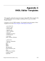
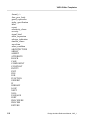
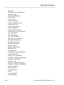
Appendix C
VHDL Editor Templates
C-1
Appendix D
Component Status Personality Module
D-1
Applications/Options
Environment Variables
DA Palettes and Menus
All Scopes
DA Session
Schematic Editor
Symbol Editor
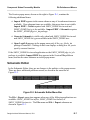
Appendix E
Pin List File Format
Pin List File Construct Dictionary
pins
body_props
shape
source_view_path
source_view_type
source_view_ver
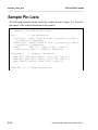
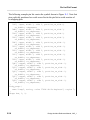
Sample Pin Lists
D-1
D-2
D-5
D-5
D-5
D-7
D-9
E-1
E-2
E-3
E-7
E-10
E-11
E-12
E-13
E-14
Index
Design Architect Reference Manual, V8.5_1
xvii
Table of Contents
LIST OF FIGURES
Figure A-1.
Figure D-1.
Figure D-2.
Figure D-3.
Figure E-1.
Figure E-2.
Figure E-3.
Figure E-4.
Figure E-5.
xviii
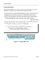
Sample Menu Item
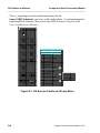
DA Session Palette and Popup Menu
Schematic Editor Menu Bar
Schematic Editor File Menu
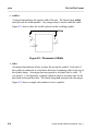
Placement of Width
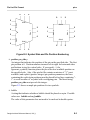
Symbol Side and Pin Position Numbering
Body Property Regions
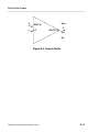
Sample Buffer
7496 Shift Register
A-23
D-6
D-7
D-8
E-4
E-5
E-8
E-15
E-17
Design Architect Reference Manual, V8.5_1
Table of Contents
LIST OF TABLES
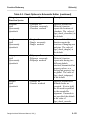
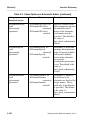
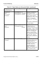
Table 1-1. Function Summary
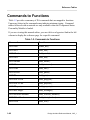
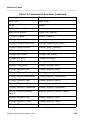
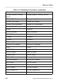
Table 1-2. Commands to Functions
Table 1-3. Session, IDW Component and IDW Hierarchy
Window Function Keys
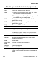
Table 1-4. Schematic Editor Window Function Keys
Table 1-5. Symbol Editor Window Function Keys
Table 1-6. VHDL Editor Window Function Keys
Table 1-7. Numeric Keypad
Table 1-8. Numeric Keypad Actions
Table 1-9. Session, IDW Component and IDW Hierarchy
Window Control Keys
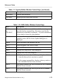
Table 1-10. Schematic Editor Window Control Keys
Table 1-11. Symbol Editor Window Control Keys
Table 1-12. VHDL Editor Window Control Keys
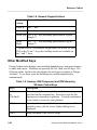
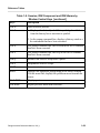
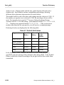
Table 2-1. Check Options Available in All Scopes
Table 2-2. Check Options in Symbol Editor
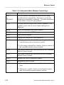
Table 2-3. Check Options in Schematic Editor
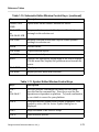
Table 2-4. $make_symbol() Option Behavior
Table 2-5. Summary of Report Check Switches
Table 2-6. Default Colors for Black and White Backgrounds
Table 2-7. Default Grid Values
Table 2-8. $setup_check_schematic() Options
Table 2-9. $$setup_check_sheet() Options
Table 2-10. $setup_check_symbol() Options
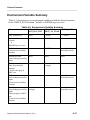
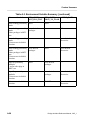
Table A-1. Customization Tasks Categorized by Re-work Level
Table A-2. Scopes Searched
in each Design Architect Window
Table A-3. Environment Variable Summary
Table B-1. Common Data Types
Design Architect Reference Manual, V8.5_1
1-2
1-48
1-58
1-60
1-63
1-66
1-67
1-68
1-68
1-70
1-71
1-73
2-145
2-146
2-148
2-365
2-428
2-523
2-536
2-568
2-573
2-579
A-3
A-6
A-27
B-1
xix
Table of Contents
LIST OF TABLES [continued]
xx
Design Architect Reference Manual, V8.5_1
About This Manual
About This Manual
The Design Architect manuals provide information for electronic design
engineers who use the following Mentor Graphics applications:
• The Schematic Editor is used to create and modify schematic diagrams.
• The Symbol Editor lets you create and modify logic symbols representing
components used in schematic diagrams.
• The VHDL Editor is used to create and modify VHDL source objects and to
compile these models for both simulation and synthesis.
The Design Architect Documentation Set consists of four manuals:
• Getting Started with Design Architect is for new users of Design Architect
who have some knowledge about schematic drawing and electronic design
and are familiar with the UNIX environment. This training workbook
provides basic instructions for using Design Architect to create schematics
and symbols.
• Design Architect User's Manual provides a basic overview of Design
Architect, key concepts for using the Schematic Editor, Symbol Editor, and
VHDL Editor, and design creation procedures.
• Design Architect Reference Manual (this manual) contains information
about the functions used to create and modify schematic and cabling
designs, logic symbols, and VHDL source files.
If you are unfamiliar with general Mentor Graphics documentation conventions or
need to know how to write a command or a function, you should first read Mentor
Graphics Corporation Documentation Conventions.
Design Architect Reference Manual, V8.5_1
xxi
About This Manual
Related Publications
• Design Architect Training Workbook is for users who have some
knowledge about schematic drawing and electronic design and are familiar
with the UNIX environment. This training workbook provides concepts
and instructions for using Design Architect to create schematics and
symbols, using the Design Viewpoint Editor to create design viewpoints.
• Properties Reference Manual contains information describing all
properties created and/or used by Mentor Graphics applications for
associating textual design data with circuit elements.
• Component Interface Browser User's and Reference Manual describes the
shell-level utility that allows you to view and edit component interfaces.
• Mentor Graphics Introduction to VHDL contains introductory conceptual
information and basic coding techniques for VHDL.
• Design Viewpoint Editor User's and Reference Manual (DVE) contains
information about defining and modifying design configuration rules for
design viewpoints, along with latching the design. You can also add,
modify and manage back annotation data for the design from within DVE.
• Design Viewing and Analysis Support Manual (DVAS) contains
information about functions and commands for selecting viewing,
highlighting, analyzing, reporting, protecting, grouping, syntax checking,
naming, and window manipulating capabilities. DVAS functions and
commands operate within applications such as QuickSim, QuickPath,
AccuSim, QuickGrade and DVE.
The following manuals provide additional useful information:
• Design Dataport User's and Reference Manual contains information about
Design Dataport (DDP), a procedural interface that can read, write, and
modify schematic sheets and symbols.
xxii
Design Architect Reference Manual, V8.5_1
About This Manual
• DFI User's and Reference Manual contains information about the Design
File Interface, a procedural interface that allows netlist read, back
annotation, and write access to a Mentor Graphics design database.
• Digital Modeling Guide contains basic information for designers and
modelers using the Mentor Graphics digital analysis environment. This
manual can help you make some rudimentary decisions in model or design
development.
• Design Manager User's Manual provides information about the concepts
and use of the Design Manager. This manual contains a basic overview of
design management and of the Design Manager, key concepts to help you
use the Design Manager, and many design management procedures.
• Design Manager Reference Manual describes the AMPLE functions that
are available in the Design Manager. This manual also describes the
Design Manager shell commands.
• AMPLE User's Manual provides overview information, flow-diagram
descriptions, explanation of important concepts, and task-oriented
procedures for customizing the common user interface and writing AMPLE
functions.
• AMPLE Reference Manual contains information about AMPLE statements
and functions that are common to all applications.
• Common User Interface Manual describes the user interface features that
are common to all Mentor Graphics products. This manual tells how to
manage and use windows, popup command line, function keys, strokes,
menus, prompt bars, and dialog boxes.
• Common User Interface Reference Manual contains information about all
of the Common User Interface functions.
Design Architect Reference Manual, V8.5_1
xxiii
About This Manual
xxiv
Design Architect Reference Manual, V8.5_1
Chapter 1
Reference Tables
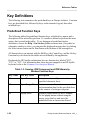
This chapter contains reference tables that summarize the functions, internal state
functions, and key definitions in Design Architect.
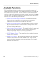
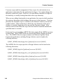
Function Summary
Table 1-1 presents the user functions that are available in Design Architect. If you
are viewing this manual online, you can click on a hypertext link in the left
column to display the reference page for a specific function.
Some functions listed in the Table 1-1 are provided with a personality module.
The names of these functions are followed by an asterisk (*) and are only
available if the Component Status Personality Module is loaded. For information
on loading personality modules, refer to Appendix A, "Custom Userware". For
information on functions/commands in other Design Architect personality
modules, refer to the following documents:
AutoLogic BLOCKS Manual
DSP Architect User's and Reference Manual
PCB Products Overview Manual
QuickHDL User's and Reference Manual
VHDLwrite User's and Reference Manual
Design Architect Reference Manual, V8.5_1
1-1
Reference Tables
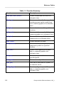
Function
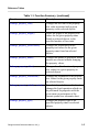
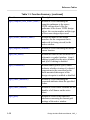
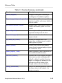
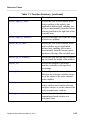
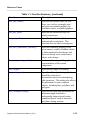
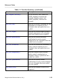
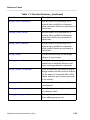
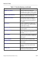
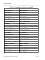
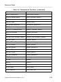
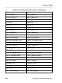
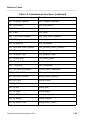
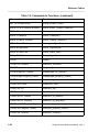
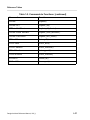
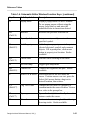
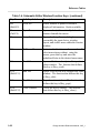
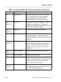
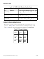
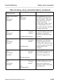
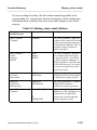
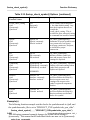
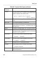
Table 1-1. Function Summary
Description
$add_ansi_sheet_border()
Creates a border and title block on a
schematic sheet.
$$add_arc()
Creates an arc from the three specified
coordinate points on the symbol body
or as comment graphics on a schematic
sheet.
$add_bus()
Creates a bus between the specified
locations.
$add_circle()
Creates a circle on a symbol body or
comment graphics on a schematic sheet.
$add_dot()
Creates a dot on a symbol, or a
comment dot on a schematic sheet.
$add_frame()
Creates and places a frame.
$add_instance()
Creates an instance of a given
component symbol at a specified
location.
$add_line()
Creates a line segment on a symbol
body or comment graphics on a
schematic sheet.
$add_net()
Creates net segments between
specified points.
$add_panel()
Creates a named panel.
$add_pin()
Adds one or more pins to a symbol, or
to schematic sheets.
$add_polygon()
Creates a polygon as part of the symbol
body or comment graphics on a
schematic sheet.
1-2
Design Architect Reference Manual, V8.5_1
Reference Tables
Function
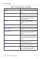
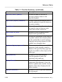
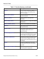
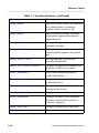
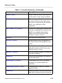
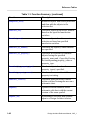
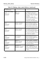
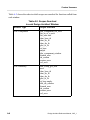
Table 1-1. Function Summary [continued]
Description
$add_polyline()
Creates a polyline on a symbol body or
comment graphics on a schematic sheet.
$add_property()
Adds the specified property with the
given value to all selected objects.
$add_property_to_handle()
Adds properties to one or more objects
identified by their associated handles,
rather than the current selection set.
$add_rectangle()
Creates a rectangle on a symbol body or
comment graphics on a schematic sheet
based on the coordinates provided.
$add_selected_instance()
Places the most current version of the
component symbol for the selected
instance on the schematic sheet.
Exactly one instance must be selected.
$add_sheet_border()
Creates a border and optional title block
for a specified sheet size.
$add_text()
Adds comment text to schematic sheets
and symbol text to symbols.
$add_wire()
Creates a net, one pixel wide, between
the specified locations.
$align()
Moves the selected objects to align with
the most extreme extent (left, right, top,
or bottom) of the selected objects.
$allow_resizable_instances()
Sets up the current sheet so that it will
allow resizable instances.
$apply_edits()
Applies the edits made to open-edit-indesign-context sheets to the in-memory
design without saving the sheets to disk.
Design Architect Reference Manual, V8.5_1
1-3
Reference Tables
Function
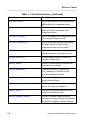
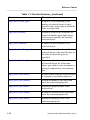
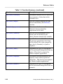
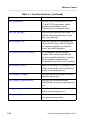
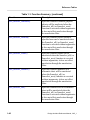
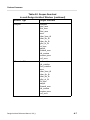
Table 1-1. Function Summary [continued]
Description
$auto_sequence_text()
Automatically sequences the values of
selected properties from top to bottom
and left to right.
$begin_edit_symbol()
Modifies an existing symbol "in place"
on a schematic sheet. Only one
instance must be selected.
$cancel_compile()
Cancels the VHDL compilation
currently in progress.
$change_color()
Changes the color of selected objects.
$change_compiled_pin_name()
Changes the compiled pin name of one
or more selected pins on a symbol, or of
one or more selected symbol pins in a
schematic.
$change_group_visibility()
Toggles the visibility of the specified
group of objects.
$change_instance_resize_factor()
Sets the current resize factor for the
selected instance(s)
$change_line_style()
Changes the style of selected lines,
polylines, or polygons.
$change_line_width()
Changes the width of selected lines,
polylines, and polygons.
$change_net_style()
Changes the drawing style of selected
net segments for schematic sheets.
$change_net_width()
Changes the width of the selected net
segments on a schematic sheet.
$change_polygon_fill()
Changes the fill of selected polygon,
rectangle, and circle objects.
1-4
Design Architect Reference Manual, V8.5_1
Reference Tables
Function
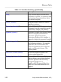
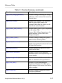
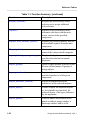
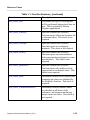
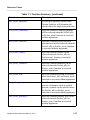
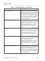
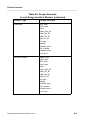
Table 1-1. Function Summary [continued]
Description
$change_property_font()
Changes the text font of the property
text value associated with a given
property on the selected objects.
$change_property_height()
Alters the height of the property text
values for the given property name
found on selected objects, to the
specified number of user units.
$change_property_justification()
Changes the justification on the
property text values for the given
property name found on selected
objects.
$change_property_name()
Changes the names of properties whose
owners are selected without changing
the property values.
$change_property_offset()
Changes the offset location of property
text values for a given property on
selected objects.
$change_property_orientation()
Changes the orientation of the property
text values for the given property name
on selected objects.
$change_property_stability_switch()
For selected symbol items, this function
changes the legal operations which can
be performed on properties with the
given name on an instance of the
current symbol in a schematic sheet.
$change_property_type()
Changes the property type of the
specified property name on selected
objects.
Design Architect Reference Manual, V8.5_1
1-5
Reference Tables
Function
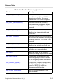
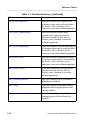
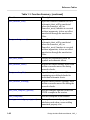
Table 1-1. Function Summary [continued]
Description
$change_property_value()
Sets a new value for all properties with
the specified name on all selected
objects.
$change_property_visibility()
Hides, displays, or toggles the visibility
of the property values for the specified
property on selected objects.
$change_property_visibility_switch() Changes property visibility on an
instance of the selected symbol.
$change_text_font()
Changes the font of selected property
values and comment text.
$change_text_height()
Alters the height of selected property
values or comment text to the specified
number of user units.
$change_text_justification()
Changes the justification of selected
property text values or comment text.
$change_text_value()
Changes the text value of a selected
property or comment.
$$check()
Performs error checking on the current
symbol or schematic sheet, or the full
schematic.
$clear_unattached_annotations()
Clears all unattached annotations from
a back annotation object the next time
the sheet is saved.
$close_selection()
Explicitly closes the current selection
set.
$close_window()
Closes an active window.
$compile()
Invokes the VHDL compiler using the
options specified with the
$set_compiler_options() function.
1-6
Design Architect Reference Manual, V8.5_1
Reference Tables
Function
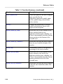
Table 1-1. Function Summary [continued]
Description
$connect()
Forces connections of net segments and
pins.
$connect_area()
Forces connections of net segments and
pins in the specified rectangular region.
$convert_to_comment()
Converts selected electrical or symbol
body objects into non-instantiable
comment graphics.
$copy()
Duplicates all selected objects,
including both electrical and comment
objects.
$copy_multiple()
Creates multiple copies of selected
objects and places the copies in a line.
$copy_to_array()
Creates multiple copies of the selected
objects.
$create_entity()
Creates a VHDL entity description that
matches the symbol in the active
window.
$create_pin_list()
Scans the specified schematic for ports
and returns a vector of pin information
or places the pin information into a pin
list file.
$create_sheet()
Creates a schematic sheet of the size
and orientation specified.
$create_symbol()
Refer to the description of the
$generate_symbol() function.
$cs_end_edit_symbol()*
Terminates the symbol edit-in-place
mode, which was invoked with the
$begin_edit_symbol() function.
Design Architect Reference Manual, V8.5_1
1-7
Reference Tables
Function
Table 1-1. Function Summary [continued]
Description
$cs_save_sheet()*
Saves the schematic sheet being edited
and updates the component status.
$cs_save_sheet_as()*
Saves the sheet being viewed, using the
name specified, and updates the
component status.
$cs_save_symbol()*
Saves and updates the component status
of the symbol being viewed.
$cs_save_symbol_as()*
Saves the symbol being viewed using
the name specified, and sets the
component status of the symbol.
$delete()
Deletes selected electrical, symbol,
comment objects, and property text.
$delete_interfaces()
Deletes empty interfaces from the
specified component.
$delete_panel()
Deletes a named panel definition on a
schematic or a symbol.
$delete_parameter()
Cancels the effect of a previous
$set_parameter() function for the
specified parameter names.
$delete_property()
Removes specified property names
from selected objects.
$delete_property_owner()
Removes a type of object from the legal
owner list of given properties.
$delete_sheet()
Deletes the specified schematic sheet
from the workstation disk.
$delete_template_name()
Deletes a template name from the
current line using the rules described in
the $select_template_name() function.
1-8
Design Architect Reference Manual, V8.5_1
Reference Tables
Function
Table 1-1. Function Summary [continued]
Description
$direct_to_active_window()
Redirects the given AMPLE string to be
evaluated in the active window.
$disconnect()
Forces disconnection of net segments
and instance pins at selected junctions
and intersections.
$disconnect_area()
Forces disconnection of net segments
and instance pins at selected junctions
and intersections in a specified area.
$does_selection_exist()
Returns whether there are any selected
objects.
$end_edit_symbol()
Terminates the symbol edit-in-place
mode, which was invoked with the
$begin_edit_symbol() function.
$expand_template_name()
Finds a template name on the current
line and replaces it with a
corresponding VHDL template.
$export_edif_netlist()*
Translates a Mentor Graphics design
into an EDIF file describing that design.
$export_miflist()*
Creates a Mentor Intermediate Format
(MIF) netlist of a design.
$export_vhdl_netlist()*
Calls $MGC_HOME/bin/vhdlnet to
produce a netlist of a VHDL model.
$find_instance()*
Opens a window on the sheet
containing an instance specified by the
instance handle found in a report
produced by $run_erc(), and zooms in
on that instance.
$filter_property_check()
Creates a list of properties that are to be
excluded from checks.
Design Architect Reference Manual, V8.5_1
1-9
Reference Tables
Function
Table 1-1. Function Summary [continued]
Description
$flip()
Flips selected objects (which can be
schematics, symbols, or comments) and
the location of any selected text about
the current basepoint.
$freeze_window()
Suspends graphic updates to symbol
and sheet windows.
$generate_schematic()*
Calls $MGC_HOME/bin/sg to create a
schematic from the connectivity model
produced by $import_edif_netlist().
$generate_symbol()
Generates a symbol of a specified shape
and size using the pin information
provided. Optional arguments
determine whether or not a window is
opened to display the generated symbol.
$get_active_symbol()
Returns a vector containing one or all of
the following attributes: the complete
pathname, the version number, the
component pathname, the component
name, and the symbol name of the
active symbol.
$get_active_symbol_history()
Returns information related to the
active symbol history list.
$get_apply_edits_needed()
Returns @true if there are edits to any
edit-in-design-context sheets that have
not been applied to the in-memory
design through the use of
$apply_edits(). Returns @false if no
edits have been made that need to be
applied.
1-10
Design Architect Reference Manual, V8.5_1
Reference Tables
Function
Table 1-1. Function Summary [continued]
Description
$get_attached_objects()
Returns information about object
handles of the specified type which are
attached to the given object, if any such
objects exists.
$get_attributes()
Returns a vector containing the location
of the specified object.
$get_auto_update_inst_handles()$
Returns auto-update information about
the sheet in the active window.
$get_basepoint()
Returns a three-element array
specifying the location of the basepoint
of the current sheet.
$get_bundle_members()
Returns a vector containing an ordered
list of the specified bundle’s members.
$get_check_status()
Determines if the sheet or symbol was
checked and if the sheet or symbol
passed or failed the check.
$get_comment_graphics_attributes()
Returns a vector containing the values
of attributes of comment graphics
specified by the handle argument and
the comment_attributes argument.
$get_comment_handles()
Returns a vector whose elements are the
handles of comment objects of the
specified type(s) in the active window.
$get_comment_text_attributes()
Returns a vector of the requested
attributes in the order in which you
specified them.
$get_comment_visibility()
Determines the visibility of comment
text and graphics.
Design Architect Reference Manual, V8.5_1
1-11
Reference Tables
Function
Table 1-1. Function Summary [continued]
Description
$get_compiled_vhdl_source_name()
Returns a vector containing the
complete pathname to the source
VHDL design object's file, the
pathname to the source VHDL design
object, the version number and the type
of the source design object used.
$get_default_interface_name()
Returns the name of the default
interface for the component that is
under edit (or being viewed) in the
active window.
$get_diagram_location()
Returns a vector containing the mouse
cursor location.
$get_edit_mode()
Returns the value of the edit mode of a
schematic or symbol window: @on if
editing is enabled in the active window,
and @off if editing is disabled.
$get_evaluations()
Returns either @on or @off, which
indicates whether viewing of evaluated
expressions in the source and/or the
back-annotated data aspect of the
design viewpoint is enabled or disabled.
$get_frame_attributes()
Returns a vector containing the
requested attributes about the specified
frame.
$get_frame_handles()
Returns a vector whose elements are the
handles of all frames on the active
sheet.
$get_grid()
Returns a vector of the requested
attributes concerning the current grid
settings of the active window.
1-12
Design Architect Reference Manual, V8.5_1
Reference Tables
Function
Table 1-1. Function Summary [continued]
Description
$get_in_design_context()
Returns either @true or @false,
indicating whether the current sheet is a
design sheet in the context of a design
viewpoint.
$get_instance_attributes()
Returns the value of all specified
attributes of the instance specified by
instance_handle.
$get_instance_handles()
Returns a vector of all instance handles
that are attached to the specified net.
$get_instance_models()
Returns detailed information about all
models available for the selected
instance.
$get_instance_pathname()
Returns a vector containing the
component pathname, the component
name, the interface name, and the
symbol name of the selected instance.
$get_item_type()
Returns one of the following item types
specified by the handle:
@comment_graphics,
@comment_text, @frame, @instance,
@net, @pin, @vertex, @symbolpin,
@property, or @net_segment.
$get_model_path()
Returns the operating system pathname
to the current model corresponding to
the specified instance.
$get_net_attributes()
Returns the Net property value assigned
to the specified net, and/or the handles
of the vertices that define that net.
$get_net_handles()
Returns a vector of the net handles
attached to the specified instance or
vertex.
Design Architect Reference Manual, V8.5_1
1-13
Reference Tables
Function
Table 1-1. Function Summary [continued]
Description
$get_next_active_symbol()
Returns the name of the next or
previous symbol, relative to the
specified symbol.
$get_object_property_attributes()
Returns requested information about a
specific property for specific objects in
the active window.
$get_objects()
Returns the specific information about
the specific types of objects on the
active sheet or the selected set.
$get_objects_in_area()
Returns a vector of handles for all
objects in the specified area.
$get_origin()
Returns the coordinates of the origin of
a symbol, which is the reference point
on the symbol that is used for placing,
copying, and moving instances of that
symbol on a schematic sheet.
$get_owned_property_names()
Returns a vector of the names of all the
properties, both currently owned by
objects of the specified item_type and
legal to be added to other objects of the
same type.
$get_parameter()
Returns a vector containing the
specified parameter name, the
associated value and type.
$get_pathname()
Returns the pathname to the
component, the schematic, if any, the
sheet or symbol name, and the version
number of the object displayed in the
active window.
$get_pin_attributes()
Returns a vector of specified attributes
for a given pin.
1-14
Design Architect Reference Manual, V8.5_1
Reference Tables
Function
Table 1-1. Function Summary [continued]
Description
$get_pin_handles()
Returns a vector of handles of pins
attached to the specified object, and/or a
matching specified pin name.
$get_pin_names()
Returns a vector of symbol pin names.
$get_property_attributes()
Returns requested information about a
specified property or a vector of
properties.
$get_property_handles()
Returns a vector of property handles
associated with the given object, or of
all properties in the active window, if
no object handle is specified.
$get_property_names()
Returns the names of all of the
properties attached to the object
(identified by its handle) in the active
window.
$get_property_owners()
Returns information on objects in the
active window to which a specified
property is attached. Property names
are always compared without regard to
case.
$get_schematic_sheets()
Returns the names of the sheets in the
specified schematic.
$get_search_path()
Returns a vector of strings, one for each
pathname in the current search path.
$get_select_count()
Returns an integer designating the
number of objects currently selected in
the active window.
Design Architect Reference Manual, V8.5_1
1-15
Reference Tables
Function
Table 1-1. Function Summary [continued]
Description
$get_select_count_type()
Returns a vector consisting of the
number of selected objects of each
specified type, in the order in which the
types were specified.
$get_select_extent()
Returns a vector of two locations: the
lower-left and the upper-right corners
of the area occupied by the currently
selected objects.
$get_select_handles()
Returns a vector of handles of all
selected objects.
$get_select_handles_type()
Returns a vector of handles of all
selected objects of the specified type in
the order in which the types are
specified.
$get_select_identical()
Determines whether members of a set
of selected objects are of the same
object type, such as a net, an instance, a
string of comment text, or a comment
line.
$get_select_text_exists()
Returns @true if the one selected object
is a property, and @false otherwise.
$get_select_text_handle()
Returns the handle of the object that
owns the selected property text.
$get_select_text_name()
Returns the property name of the
selected text.
$get_select_text_origin()
Returns the location of the object that
owns the selected property text.
$get_select_text_value()
Returns the property value of the
selected property text.
1-16
Design Architect Reference Manual, V8.5_1
Reference Tables
Function
Table 1-1. Function Summary [continued]
Description
$get_sheet_design_pathname()
Returns a string containing the design
pathname of the instance that owns the
current sheet.
$get_sheet_extent()
Returns two locations: the lower-left
and the upper-right corners of a
rectangle enclosing the objects on the
sheet in the active window.
$get_source_edit_allowed()
Returns either @on or @off, depending
on the value of the
Source_Edit_Allowed property on the
parent instance in the context of a
design viewpoint.
$get_symbol_name()
Returns a string defining the symbol
name for the current symbol.
$get_text_information()
Returns information such as value,
height, and justification about the text at
the specified location.
$get_type_present()
Returns whether the specified object
exists on the sheet.
$get_vertex_attributes()
Returns a vector of the requested
attributes of the vertex specified by the
vertex handle.
$get_vertex_handles()
Returns a vector of all vertex handles
that are attached to the specified net.
$get_view_area()
Returns a vector containing the
locations of the lower left and upper
right corners of the current view in the
active window.
$get_viewpoint()
Returns a string defining the session
viewpoint pathname.
Design Architect Reference Manual, V8.5_1
1-17
Reference Tables
Function
Table 1-1. Function Summary [continued]
Description
$get_window_names()
Returns a vector containing the
specified information about all
windows in the session.
$group()
Defines or adds to groups of design
objects for quicker editing operations
on those objects.
$hide_active_symbol_window()
Hides the active symbol window from
view.
$hide_annotations()
Turns off the display of back-annotated
property values and makes them
uneditable in the context of the design
viewpoint.
$hide_comment()
Hides comment text and graphics.
Hidden comments are not selectable.
$hide_context_window()
Turns off the display of the context
window.
$hide_panel_border()
Removes the visible borders of the
named panels.
$hide_status_line()
Hides the status line in an editor.
$highlight_by_handle()
Highlights all unselected, unprotected
electrical and comment objects having
the specified handles.
$highlight_property_owner()
Highlights the owner of a visible
property text string, assuming the
owner is currently unselected and
unprotected.
$import_edif_netlist()*
Invokes $MGC_HOME/bin/enread
with the specified EDIF netlist file to
produce a connectivity model.
1-18
Design Architect Reference Manual, V8.5_1
Reference Tables
Function
Table 1-1. Function Summary [continued]
Description
$insert_template()
Displays a dialog box containing a
scrolling list of available templates.
$is_active_symbol_window_visible() Returns @true if the active symbol
window is visible, and returns @false if
it is not visible.
$is_context_window_visible()
Returns @true if the context window is
visible, and returns @false if it is not
visible.
$is_handle_valid()
Returns @true if the specified handle
represents an object on the sheet.
$is_selection_open()
Determines whether the selection set is
open or closed.
$is_status_line_visible()
Returns the current state of the
status_line_visibility internal variable:
either @true or @false.
$make_symbol()
Creates a new symbol and instance
from selected comment and pin objects
on a schematic sheet.
$mark_property_value()
Marks a property value as modified (or
not modified) on this instance.
$measure_distance()
Measures the vector distance and angle
between two points and displays the
delta-X or delta-Y, and the Cartesian
angle, for straight line distances in the
message area at the bottom of the
Design Architect Session Window.
$merge_annotations()
Merges all annotated property values to
the source sheet in the context of a
design viewpoint.
Design Architect Reference Manual, V8.5_1
1-19
Reference Tables
Function
Table 1-1. Function Summary [continued]
Description
$modify_frame()
Moves and resizes the selected frame to
the rectangular region defined by the
coordinates.
$move()
Moves all selected object(s) to a new
position that you specify, either by
entering coordinates, or by placing the
cursor at the desired location.
$move_cursor_incrementally()
Enables moving the mouse cursor
incrementally, typically in response to
using the keyboard "arrow" keys.
$open_design_sheet()
Invokes the Schematic Editor in the
context of a design viewpoint which
allows you to create, edit, or view
source and back annotation data.
$open_down()
Opens a sheet one hierarchical level
down from a selected instance in the
context of a design viewpoint.
$open_sheet()
Allows you to edit or view a schematic
sheet.
$open_source_code()
Opens a source code editor for the
specified language.
$open_symbol()
Allows you edit or view a symbol.
$open_up()
Opens the parent sheet of the currently
viewed sheet in the context of a design
viewpoint.
$open_vhdl()
Opens a VHDL Editor window on the
specified version of the VHDL source
design object.
1-20
Design Architect Reference Manual, V8.5_1
Reference Tables
Function
Table 1-1. Function Summary [continued]
Description
$pivot()
Pivots selected electrical, symbol, or
comment objects individually about
their own origins.
$place_active_symbol()
Places the current active symbol at the
specified location.
$print_all_sheets()
Prints all sheets in the specified
hierarchy.
$print_design_sheets()
Prints all sheets in a design that display
annotations.
$print_schematic_sheets()
Prints all of the sheets in a schematic.
$protect()
Adds all the selected objects to the set
of protected items.
$protect_area()
Adds all the objects within the specified
rectangular region to the set of
protected items.
$recalculate_properties()
Recalculates all property expressions
on a design sheet that has been opened
in the context of a design viewpoint.
$reconnect_annotations()
Reconnects the back annotations from
an object that no longer exists in the
design onto an object that does exist in
the design.
$redo()
Returns the application to the state
existing prior to the previous $undo()
function.
$remove_comment_status()
Removes comment status from
selected symbol components.
Design Architect Reference Manual, V8.5_1
1-21
Reference Tables
Function
Table 1-1. Function Summary [continued]
Description
$reopen_selection()
Reopens the most recently closed
selection set to accept additional
selected items.
$replace()
Replaces selected instances in the
schematic edit sheet with the most
recent version of the specified
component.
$replace_with_alternate_symbol()
Replaces the selected instance with the
next available symbol from the same
component.
$$report_check()
Creates a report containing the check
status of the various check categories.
$report_default_property_settings()
Displays the legal owners and types of
specified electrical and comment
properties.
$report_groups()
Opens a report window in which it lists
the user-defined names of groups of
design objects.
$report_interfaces()
Reports information contained in the
specified interface(s) of the given
component.
$report_interfaces_selected()
Reports information about the
interface(s) of the selected instance.
$report_object()
Creates a report for requested objects
or, if no handles are specified, for
selected objects of the types indicated
by the arguments.
$report_panels()
Lists the names and locations of all
panels in either a popup window, a
transcript window, and/or a file.
1-22
Design Architect Reference Manual, V8.5_1
Reference Tables
Function
Table 1-1. Function Summary [continued]
Description
$report_parameter()
Lists the design parameters declared
with the $set_parameter() function.
$reselect()
Selects the previously closed selection
set (called the reselection set).
$revalidate_models()
Validates all of the models that are
registered with the same interface as the
specified symbol.
$rotate()
Rotates all selected electrical and
comment objects as a unit around the
basepoints.
$route()
Replaces segments between selected
vertices with an orthogonal net.
$run_erc()*
Opens a viewpoint on the design
containing the sheet in the active
window, adds the Comp property as a
primitive, checks the design using the
specified QuickCheck Electrical Rules
Check (ERC) file, writes a file to be
used by the $find_instance() function,
then displays the check report in a
notepad window.
$save_sheet()
Writes the schematic data to the disk for
the design being viewed in the active
window.
$save_sheet_as()
Writes the schematic sheet to the disk,
using the name specified by the name
arguments for the design being viewed
in the active window.
$save_symbol()
Writes the symbol to the disk for the
design being viewed in the active
window.
Design Architect Reference Manual, V8.5_1
1-23
Reference Tables
Function
Table 1-1. Function Summary [continued]
Description
$save_symbol_as()
Writes the symbol to the disk, using the
name specified by the
component_name and symbol_name,
for the symbol being viewed in the
active window.
$scale()
Changes the proportions of selected
symbol and comment objects with
respect to the basepoint.
$scroll_down_by_unit()
Scrolls the view of the contents in the
active window down by one
application-defined unit, enabling you
to move incrementally from the current
cursor position to the bottom of the
viewable area.
$scroll_down_by_window()
Scrolls the view into the active window
down by one-fourth the height of the
window.
$scroll_hz()
Horizontally scrolls by the specified
percentage of the active window.
$scroll_left_by_unit()
Scrolls the view of the contents in the
active window to the left by one
application-defined unit, enabling you
to move incrementally from the current
window position to the left of the
viewable area.
$scroll_left_by_window()
Scrolls the view into the active window
to the left, one-fourth the width of the
window.
1-24
Design Architect Reference Manual, V8.5_1
Reference Tables
Function
Table 1-1. Function Summary [continued]
Description
$scroll_right_by_unit()
Scrolls the view of the contents in the
active window to the right by one
application-defined unit, enabling you
to move incrementally from the current
window position to the right side of the
viewable area.
$scroll_right_by_window()
Scrolls to the right, one-fourth the width
of the active window.
$scroll_up_by_unit()
Scrolls the view of the contents in the
active window up one applicationdefined unit, enabling you to move
incrementally from the current cursor
position to the top of the viewable area.
$scroll_up_by_window()
Scrolls the view into the active window
up one-fourth the height of the window.
$scroll_vt()
Scrolls the contents of the active
window vertically by the specified
percentage.
$select_all()
Selects objects in the active window
based on the selection switches chosen,
or on the values of the select internal
state variables.
$select_area()
Selects objects in a given area in the
active window based on the selection
switches chosen, or on the values of the
select internal state variables.
$select_branches()
Selects the entire branch of any net
containing selected vertices on a
schematic sheet.
Design Architect Reference Manual, V8.5_1
1-25
Reference Tables
Function
Table 1-1. Function Summary [continued]
Description
$select_by_handle()
Selects all unprotected objects
(schematics, symbols, and comments)
with the specified handles.
$select_by_property()
Selects objects based on the property
names, values, and types specified.
Multiple property name/value/type sets
can be specified with this function.
$select_by_property_type()
Selects objects based on the property
type(s) specified.
$select_group()
Selects all objects in the named group.
$select_instances()
Selects all unselected instances that
have selected pins.
$select_nets()
Selects all unselected net segments and
vertices of nets that have at least one
selected net segment or vertex.
$select_pins()
Selects pins of selected instances.
$select_property_owner()
Selects the owner of a visible property
text string.
$select_template_name()
Selects the next VHDL template name
on the current line by searching for text
between the following types of
brackets: "<>", "{}", or "[]".
$select_text()
Selects only text objects in the specified
area in the active window.
$select_vertices()
Selects either pin or net vertices within
a defined area.
$sequence_text()
Allows assignment of sequenced
property values.
1-26
Design Architect Reference Manual, V8.5_1
Reference Tables
Function
Table 1-1. Function Summary [continued]
Description
$set_active_symbol()
Specifies a new active symbol to be
instantiated whenever the
$place_active_symbol() function is
issued.
$set_active_symbol_history()
Adds items to the active symbol history
list, or replaces the items in the list.
$set_annotation_visibility()
Determines whether annotated values
are displayed and editable in the context
of a design viewpoint.
$set_auto_update_mode()
Specifies whether an automatic update
is performed when a sheet is opened,
and specifies how to update instances at
that time.
$set_autoripper()
This function is now obsolete. Refer to
the $set_ripper_mode() function.
$set_autoroute()
Determines whether nets are
automatically orthogonally routed when
a net is created or moved.
$set_autoselect()
Specifies whether newly-created
objects are selected after being created.
$set_basepoint()
Changes the basepoint of the selected
objects to the specified location.
$set_bus_width()
Specifies the width for subsequently
created buses.
$set_check_annotations()
Determines whether checks are done
for annotations to fixed or protected
properties, and whether checks for
unattached annotations are done.
Design Architect Reference Manual, V8.5_1
1-27
Reference Tables
Function
Table 1-1. Function Summary [continued]
Description
$set_check_closedots()
Determines whether or not to check for
the occurrence of close-dots in the
schematic area.
$set_check_dangle()
Specifies whether dangling nets and
pins are identified by the $$check()
function.
$set_check_expression()
Determines whether or not the
$$check() function identifies
expressions on the sheet.
$set_check_filemode()
Specifies how information is to be
stored in the file defined by the
check_filename internal state variable.
$set_check_filename()
Specifies the name of the file in which
all messages generated at check time
will be stored if the value returned by
$get_check_filemode() is @add or
@replace.
$set_check_frame()
Determines the type of checking that
will be performed during check time on
frames. This check is required by
Mentor Graphics applications.
$set_check_initprops()
Determines whether mismatched Init
property values will be reported at
check time. This check is not required
by Mentor Graphics applications.
$set_check_instance()
Determines the type of checking that
will be performed during check time on
instances.
1-28
Design Architect Reference Manual, V8.5_1
Reference Tables
Function
Table 1-1. Function Summary [continued]
Description
$set_check_net()
Determines the type of checking that
will be performed during check time on
nets. This is required by Mentor
Graphics applications.
$set_check_notdots()
Specifies whether the $$check()
function reports all not-dot locations on
a schematic sheet. This check is not
required.
$set_check_overlap()
Specifies whether the $$check()
function reports on overlapping
instances. This check is not required.
$set_check_owner()
Specifies whether the $$check()
function reports any inconsistencies
between properties and property owner
specifications. This check is not
required.
$set_check_parameter()
Specifies whether the $$check()
function reports all variables used in
expressions on a schematic sheet. This
check is not required.
$set_check_pins()
Determines whether or not symbol pins
remaining on a sheet are identified by
the $$check() function. This check is
required.
$set_check_schematicinstance()
Determines whether instance names
are checked on all sheets of the
schematic, and instances not having
unique names are listed. This check is
not required.
Design Architect Reference Manual, V8.5_1
1-29
Reference Tables
Function
Table 1-1. Function Summary [continued]
Description
$set_check_schematicinterface()
Determines the type of checking that
will be performed during check time on
interfaces. This is not required by
Mentor Graphics applications.
$set_check_schematicnet()
Determines whether schematic-wide
net checks are performed such as
checking for on/off-page connectors.
This check is not required.
$set_check_schematicspecial()
Specifies whether to check for
matching on- and off-page connectors
between multiple sheets of a schematic.
This check is not required.
$set_check_schematicuserrule()
Specifies whether the $$check()
function should perform user-defined
checks on a schematic. This check is
not required.
$set_check_special()
Specifies whether the $$check()
function reports errors and warnings on
special instances, such as bus rippers,
net connectors, globals, off-page
connectors, and ports. This check is
required.
$set_check_symbolbody()
Specifies whether the $$check()
function reports symbol body errors and
warnings. This check is required.
$set_check_symbolinterface()
Determines whether the symbol's
registered interface is checked. This
check is not required.
$set_check_symbolpin()
Specifies whether the $$check()
function reports symbol pin errors and
warnings. This check is required.
1-30
Design Architect Reference Manual, V8.5_1
Reference Tables
Function
Table 1-1. Function Summary [continued]
Description
$set_check_symbolspecial()
The value of this function determines if
special instances (those with Class
property) are checked for proper
construction. This check is required.
$set_check_symboluserrule()
Specifies whether the $$check()
function should perform user-defined
checks on a symbol. This check is not
required.
$set_check_transcript()
Controls whether information is
displayed in a transcript window at
check time.
$set_check_userrule()
Specifies whether user-defined checks
are executed on schematic sheets by the
$$check() function. This check is not
required.
$set_check_window()
Controls whether information is
displayed in a window at check time.
$set_close_dot()
Specifies whether closedots are visible
or hidden on a schematic sheet.
$set_color()
Resets the color for the selected
class(es) of design objects session wide.
$set_color_config()
Changes the background color and
resets design object colors to defaults
for all design objects and all windows.
$set_compiler_options()
Displays the Compiler Options dialog
box for the language being edited
(usually VHDL) by calling the
language specific function.
$set_default_parts_menu()
Sets the default parts menu to the
specified name.
Design Architect Reference Manual, V8.5_1
1-31
Reference Tables
Function
Table 1-1. Function Summary [continued]
Description
$set_dot_size()
Specifies the size of the junction,
comment, and instantiated dots on a
schematic sheet, and the size of graphic
dots in a symbol.
$set_dot_style()
Specifies the style of the junction,
comment, and instantiated dots on a
schematic sheet, and the style of
graphic dots in a symbol.
$set_dynamic_rounding_precision()
Determines the number of significant
digits that are displayed for all location
coordinates entered with a dynamic.
$set_edit_mode()
Changes the mode of the schematic or
symbol window from edit to read-only
or from read-only to edit.
$set_environment_dofile_pathname() Sets the pathname to an AMPLE dofile
to be executed each time an object of
the specified type is opened.
$set_evaluations()
Toggles viewing of evaluated
expressions in the source and/or the
back-annotated data aspect of the
design viewpoint.
$set_grid()
Configures and displays the grid for the
active window.
$set_implicit_ripper()
Determines whether an implicitly
ripped net is attached to a bundle at a
45- or 90-degree angle.
$set_line_style()
Specifies the default style for new lines,
arcs, circles, rectangles, and polygons
in comment graphics for schematic
sheets, or graphic objects for symbols.
1-32
Design Architect Reference Manual, V8.5_1
Reference Tables
Function
Table 1-1. Function Summary [continued]
Description
$set_line_width()
Specifies the default width for new
lines, arcs, circles, rectangles, and
polygons in comment graphics for
schematic sheets, or symbol graphics.
$set_net_style()
Specifies the default net style for
newly-created nets.
$set_net_width()
Specifies the default width for
subsequently-created nets. This
function does not affect existing nets.
$set_new_annotation_visibility()
Specifies whether a property of the
given name is visible or hidden when it
is back-annotated to the design, and
does not already exist on the source
object in the design.
$set_next_active_symbol()
Activates the next symbol (graphical
representation) of the current
component.
$set_origin()
Specifies the origin of a symbol.
$set_orthogonal()
Specifies if the object being edited
should be restricted to
horizontal/vertical movement during
edit operations. This setting also affects
the placement of some comment
objects, including lines, polylines, and
polygons.
$set_orthogonal_angle()
Specifies the value that determines the
maximum angle at which to
orthogonally snap nets and certain
comment objects, such as lines and
polylines, during creation.
Design Architect Reference Manual, V8.5_1
1-33
Reference Tables
Function
Table 1-1. Function Summary [continued]
Description
$set_parameter()
Assigns values to parameters in FOR,
IF, and CASE expressions, and in
parameterized property value
expressions on a schematic sheet.
$set_pin_spacing()
Specifies pin spacing in user units. To
find the current pin spacing, execute
$get_pin_spacing().
$set_polygon_fill()
Specifies whether new polygons and
circles will be clear, solid, or stippled
for comment graphics in schematic
sheets and symbol graphics.
$set_previous_active_symbol()
For components having multiple
symbols, this function activates the
previous symbol in the list of symbols
for the current component (not
necessarily the previous active symbol).
$set_property_font()
Specifies the name of a registered font
family in which the font is defined for
newly-created property text.
$set_property_height()
Specifies the default height for newlycreated property text.
$set_property_hjustification()
Specifies the default horizontal
justification for newly-created property
text.
$set_property_orientation()
Specifies the default text orientation for
newly-created property text.
$set_property_owner()
Defines the types of objects that may
own particular properties.
1-34
Design Architect Reference Manual, V8.5_1
Reference Tables
Function
Table 1-1. Function Summary [continued]
Description
$set_property_stability_switch()
Specifies the symbol default setting for
how newly-created symbol properties
can be modified on an instance.
$set_property_transparency()
Specifies whether objects beneath
newly-created property text are
transparent.
$set_property_type()
Sets the default type for the values of
given property names, when assigned to
objects in the active window.
$set_property_visibility()
Specifies whether newly-created
instance-specific properties are visible.
$set_property_visibility_switch()
Specifies whether newly-created
properties on an instance of a symbol
are visible.
$set_property_vjustification()
Specifies the default vertical text
justification for newly-created property
text.
$set_report_filemode()
Specifies how information is to be
stored in the file defined by the
report_filename internal state variable.
$set_report_filename()
Specifies the name of the file in which
reports generated from the
$$report_check(),
$report_default_property_settings(),
$report_interfaces(), $report_object(),
$report_panels(), and
$report_parameter() functions are
stored, if the value of the
report_filemode internal state function
is either @add or @replace.
Design Architect Reference Manual, V8.5_1
1-35
Reference Tables
Function
Table 1-1. Function Summary [continued]
Description
$set_report_transcript()
Controls whether information is
displayed in a transcript window when
a $report_* function is executed.
$set_report_window()
Controls whether information is
displayed in a window during a
$report_* function.
$set_ripper_dot()
Specifies whether junction dots appear
where bus rippers join bus lines on a
schematic sheet.
$set_ripper_mode()
Determines whether the session uses
implicit rippers, automatic ripper
insertion, or neither, when wires are
connected to buses and bundles.
$set_ripper_query()
Determines whether you are asked to
supply a net name or bit number when
using the $add_wire() function to route
a single-bit net to a bundle or bus.
$set_ripper_symbol_pathname()
Specifies the default single bit bus
ripper to automatically insert in newly
created nets.
$set_schem_check_mode()
Specifies whether a schematic check
should save sheets that previously did
not pass check, but now check
successfully.
$set_schematicuserrules_file()
Specifies the pathname to a file
containing user-defined checks for a
schematic design.
$set_search_path()
Specifies directory names in which to
search for components for instantiation.
1-36
Design Architect Reference Manual, V8.5_1
Reference Tables
Function
Table 1-1. Function Summary [continued]
Description
$set_select_aperture()
Sets the pick aperture within which
Design Architect will determine the
closest object for single point selection.
$set_select_comment()
Specifies whether comment graphics
will be selected when the $select_all()
or $select_area() function is executed
without arguments.
$set_select_exterior()
Specifies whether objects outside a
specified area will be selected when the
$select_all() or $select_area() function
is executed without arguments.
$set_select_frame()
Specifies whether frames can be
selected when the $select_all() or
$select area() function is executed
without arguments.
$set_select_instance()
Specifies whether instances can be
selected when the $select_all() or
$select_area() function is executed
without arguments.
$set_select_net()
Specifies whether nets can be selected
when the $select_all() or $select_area()
function is executed without arguments.
$set_select_pin()
Specifies whether instance or symbol
pins on a schematic sheet or symbol
pins on a symbol can be selected when
the $select_all() or $select_area()
function is executed without arguments.
$set_select_property()
Specifies whether property text can be
selected when the $select_all() or
$select_area() function is executed
without arguments.
Design Architect Reference Manual, V8.5_1
1-37
Reference Tables
Function
Table 1-1. Function Summary [continued]
Description
$set_select_segment()
Specifies whether net segments on a
schematic sheet can be selected when
the $select_all() or $select_area()
function is executed without arguments.
$set_select_symbolbody()
Specifies whether symbol body
graphics and symbol text can be
selected when the $select_all() or
$select_area() function is executed
without arguments.
$set_select_symbolpin()
Specifies whether or not symbol pins on
a schematic sheet can be selected when
the $select_all() or $select_area()
function is executed without arguments.
$set_select_text()
Specifies whether comment text inside
the selection area can be selected when
the $select_all() or $select_area()
function is executed without arguments.
$set_select_vertex()
Specifies whether net vertices can be
selected when the $select_all() or
$select_area() function is executed
without arguments.
$set_selection_model()
Specifies whether object selection is
individual or additive.
$set_snap()
Specifies whether object placement is
snapped to the snap grid points in the
current window.
$set_symboluserrules_file()
Specifies the pathname to a file
containing user-defined checks for
symbols.
1-38
Design Architect Reference Manual, V8.5_1
Reference Tables
Function
Table 1-1. Function Summary [continued]
Description
$set_template_directory()
Sets the directory that contains the
VHDL templates used when the
$expand_template_name() and
$insert_template() functions are
invoked.
$set_text_font()
Specifies a filename containing the font
definitions for comment text on a
schematic sheet and symbol text on a
symbol.
$set_text_height()
Specifies the default height for newlycreated comment text on a schematic
sheet, and symbol text on a symbol.
$set_text_hjustification()
Specifies the default horizontal
justification for newly-created
comment text on a schematic sheet and
symbol text on a symbol.
$set_text_orientation()
Specifies the default text orientation for
newly-created comment text on a
schematic sheet and symbol text on a
symbol.
$set_text_transparency()
Specifies whether objects beneath
newly-created comment text on
schematic sheets or symbol text on a
symbol are visible.
$set_text_vjustification()
Specifies the default vertical
justification of newly-created comment
text on a schematic sheet and symbol
text on a symbol.
$set_undo_level()
Specifies the number of undo levels
supported.
Design Architect Reference Manual, V8.5_1
1-39
Reference Tables
Function
Table 1-1. Function Summary [continued]
Description
$set_unselect_comment()
Specifies whether comment graphics
objects will be unselected when the
$unselect_all() or $unselect_area()
function is executed without arguments;
it does not affect unselection through
the unselection filter.
$set_unselect_exterior()
Specifies whether objects outside a
specified area can be unselected when
the $unselect_all() or $unselect_area()
function is executed without arguments;
it does not affect unselection through
the unselection filter.
$set_unselect_frame()
Specifies whether frames will be
unselected when the $unselect_all() or
$unselect_area() function is executed
without arguments; it does not affect
unselection through the unselection
filter.
$set_unselect_instance()
Specifies whether instances on a
schematic sheet will be unselected
when the $unselect_all() or
$unselect_area() function is executed
without arguments; it does not affect
unselection through the unselection
filter.
$set_unselect_net()
Specifies whether nets on a schematic
sheet will be unselected when the
$unselect_all() or $unselect_area()
function is executed without arguments;
it does not affect unselection through
the unselection filter.
1-40
Design Architect Reference Manual, V8.5_1
Reference Tables
Function
Table 1-1. Function Summary [continued]
Description
$set_unselect_pin()
Specifies whether instance or symbol
pins on a schematic sheet or symbol pin
on a symbol will be unselected when
the $unselect_all() or $unselect_area()
function is executed without arguments;
it does not affect unselection through
the unselection filter.
$set_unselect_property()
Specifies whether property text will be
unselected when the $unselect_all() or
$unselect_area() function is executed
without arguments; it does not affect
unselection through the unselection
filter.
$set_unselect_segment()
Specifies whether net segments will be
unselected when the $unselect_all() or
$unselect_area() function is executed
without arguments; it does not affect
unselection through the unselection
filter.
$set_unselect_symbolbody()
Specifies whether symbol body
graphics and text will be unselected
when the $unselect_all() or
$unselect_area() function is executed
without arguments; it does not affect
unselection through the unselection
filter.
$set_unselect_symbolpin()
Specifies whether or not a symbol pin
on a sheet will be unselected when the
$unselect_all() or $unselect_area()
function is executed without arguments;
it does not affect unselection through
the unselection filter.
Design Architect Reference Manual, V8.5_1
1-41
Reference Tables
Function
Table 1-1. Function Summary [continued]
Description
$set_unselect_text()
Specifies whether comment text on a
schematic sheet will be unselected
when the $unselect_all() or
$unselect_area() function is executed
without arguments; it does not affect
unselection through the unselection
filter.
$set_unselect_vertex()
Specifies whether net vertices on a
schematic sheet will be unselected
when the $unselect_all() or
$unselect_area() function is executed
without arguments; it does not affect
unselection through the unselection
filter.
$set_user_units()
Defines the coordinate system for
symbol and schematic sheets.
$set_userrule_error()
Reports the check userrule errors from
within a userrule macro file during
userrule checks.
$set_userrules_file()
Specifies the pathname to a file
containing user-defined checks for
individual schematic sheets.
$set_userrule_warning()
Reports check userrule warnings from
within a userrule macro file during the
userrule checks.
$set_vhdl_compiler_options()
Sets the compiler options for the next
VHDL compile in the session.
$set_viewpoint()
Sets the viewpoint of the session.
$setup_annotated_property_text()
Sets up the annotated property text
attributes used when you are adding
annotated property text.
1-42
Design Architect Reference Manual, V8.5_1
Reference Tables
Function
Table 1-1. Function Summary [continued]
Description
$setup_check_schematic()
Sets the values of a specified set of
internal state variables to determine
what schematic checks are performed at
check time.
$$setup_check_sheet()
Sets the values of a specified set of
internal state variables to determine
what sheet checks are performed at
check time.
$setup_check_symbol()
Sets the values of a specified set of
internal state variables to determine
what symbol checks are performed at
check time.
$setup_color()
Sets the default colors for all design
objects of a given type.
$setup_comment()
Sets up the comment graphic and
comment text attributes that are used
when creating schematic comments.
$setup_default_viewpoint()
Tells DA that this user wants to edit in
design context and also sets the defaults
for the name of viewpoints that will be
edited, and their type in case one needs
to be created.
$setup_net()
Sets up attributes that are used when
creating nets.
$setup_page()
Specifies the pin spacing for a symbol
or schematic sheet.
$setup_property_text()
Sets up the property text attributes used
when adding property text.
Design Architect Reference Manual, V8.5_1
1-43
Reference Tables
Function
Table 1-1. Function Summary [continued]
Description
$setup_report()
Specifies whether reports are displayed
in a popup window, a transcript
window, and/or stored in a file.
$setup_ripper()
Specifies various settings associated
with implicit ripping and automatic
ripper insertion.
$setup_select_filter()
Sets up what type of objects are
currently selectable.
$setup_symbol_body()
Sets up the graphic attributes used when
creating symbol graphics and symbol
text.
$setup_unselect_filter()
Sets up what type of objects are
currently unselectable.
$show_active_symbol_window()
Displays the graphics and default body
properties for the active symbol.
$show_annotations()
Makes back-annotated properties
visible and editable.
$show_comment()
Displays comment text and graphics on
a schematic sheet.
$show_context_window()
Turns on the display of the context
window in the session.
$show_panel_border()
Displays borders of the named panels.
$show_registration()
Displays the name of the component
interface with which the symbol is
currently registered.
$show_status_line()
Displays the status line in an editor.
$slice()
Slices the selected object.
1-44
Design Architect Reference Manual, V8.5_1
Reference Tables
Function
Table 1-1. Function Summary [continued]
Description
$snap_to_grid()
Snaps comment objects and properties
to the nearest "snap" grid coordinates.
$sort_handles()
Returns an array whose elements are
the same elements as the input array,
but sorted as specified by the method,
block_size, and block_offset
arguments.
$sort_handles_by_property()
Removes all non-property handles and
sorts the remaining list of property text
handles according to the property
names associated with them, then
returns a vector of vectors.
$stretch()
Stretches the selected object.
$string_to_literal()
Returns either the given argument or
the literal value, if the argument was a
string.
$undo()
Reverses the action of the previous
undoable function called in any open
window (active, or not).
$unfreeze_window()
Resumes graphic updates to symbol and
schematic windows.
$ungroup()
Removes the grouping of all objects in
a specified group.
$unhighlight_by_handle()
Unhighlights the objects, including
property text, whose handles are
specified.
$unhighlight_property_owner()
Unhighlights the owner of a visible
property string.
$unprotect()
Removes objects from select protection
and adds the objects to the selection list.
Design Architect Reference Manual, V8.5_1
1-45
Reference Tables
Function
Table 1-1. Function Summary [continued]
Description
$unprotect_area()
Removes objects from select protection
and then adds the objects to the
selection list.
$unselect_all()
Unselects objects in the active window
based on the specified unselection
switches.
$unselect_area()
Removes objects from the current
selection set based on specified
unselection switches.
$unselect_by_handle()
Unselects the object(s) whose handles
are specified.
$unselect_by_property()
Unselects all electrical or comment
objects having the specified
property_name and, if specified, having
the corresponding property_value or
property_type.
$unselect_by_property_type()
Unselects objects based on the
property type(s) specified.
$unselect_property_owner()
Unselects the owner of a visible
property text string.
$unselect_vertices()
Unselects either pin or net vertices
within a defined rectangular area on a
schematic sheet.
$update()
Updates selected instances on the
schematic edit sheet with the current
version of the same symbol.
$update_all()
Synchronizes all sheets and symbols
open in a Design Architect session.
1-46
Design Architect Reference Manual, V8.5_1
Reference Tables
Function
Table 1-1. Function Summary [continued]
Description
$update_all_sheets()
Opens all sheets in the specified
hierarchy one at a time with the switch
specified in the update_type argument.
$update_from_interface()
Updates the specified symbol's pin and
property values from the interface.
$update_title_block()
Causes the title block on a sheet to
show the name of the user editing the
sheet, along with the date and time of
the update.
$view_all()
Shrinks or enlarges the image in the
current window so the entire design is
visible in the window.
$view_area()
Displays the specified rectangle in the
current window.
$view_centered()
Centers the view on the point specified
without changing the magnification of
the view.
$view_panel()
Centers the named panel, changing the
magnification as needed to display the
entire panel.
$view_selected()
Centers the view on selected items.
$was_saved()
Determines if unsaved edits exist in the
active sheet.
$zoom_in()
Expands the image size in the active
window to show more detail in that
window.
$zoom_out()
Zooms out from the center of the active
window by the factor specified.
Design Architect Reference Manual, V8.5_1
1-47
Reference Tables
Commands to Functions
Table 1-2 provides a summary of DA commands that are mapped to functions.
Uppercase letters in the command name indicate minimum typing. Command
names followed with an asterisk are only available when the Component Status
Personality Module is loaded.
If you are viewing this manual online, you can click on a hypertext link in the left
column to display the reference page for a specific command.
Command
Table 1-2. Commands to Functions
Function
ADD ARc
$$add_arc()
ADD BUs
$add_bus()
ADD CIrcle
$add_circle()
ADD DOt
$add_dot()
ADD FRame
$add_frame()
ADD INstance
$add_instance()
ADD LIne
$add_line()
ADD PANel
$add_panel()
ADD PIn
$add_pin()
ADD POLYGon
$add_polygon()
ADD POLYLine
$add_polyline()
ADD PRoperty
$add_property()
ADD RECtangle
$add_rectangle()
ADD SElected Instance
$add_selected_instance()
ADD SHeet Border
$add_sheet_border()
ADD TExt
$add_text()
1-48
Design Architect Reference Manual, V8.5_1
Reference Tables
Table 1-2. Commands to Functions [continued]
Command
Function
ADD WIre
$add_wire()
ALIgn
$align()
AUTo SEquence Text
$auto_sequence_text()
BEGin EDit Symbol
$begin_edit_symbol()
CANcel COmpile
$cancel_compile()
CHAnge COlor
$change_color()
CHAnge COmpiled Pin Name
$change_compiled_pin_name()
CHange GRoup Visibility
$change_group_visibility()
CHAnge LIne Style
$change_line_style()
CHAnge LIne Width
$change_line_width()
CHAnge NEt Style
$change_net_style()
CHAnge NEt Width
$change_net_width()
CHAnge POlygon Fill
$change_polygon_fill()
CHAnge PRoperty Font
$change_property_font()
CHAnge PRoperty Height
$change_property_height()
CHAnge PRoperty Justification
$change_property_justification()
CHAnge PRoperty Name
$change_property_name()
CHAnge PRoperty OFfset
$change_property_offset()
CHAnge PRoperty ORientation
$change_property_orientation()
CHAnge PRoperty Stability
Switch
$change_property_stability_switch()
CHAnge PRoperty Type
$change_property_type()
CHAnge PRoperty VAlue
$change_property_value()
CHAnge PRoperty VIsibility
$change_property_visibility()
Design Architect Reference Manual, V8.5_1
1-49
Reference Tables
Table 1-2. Commands to Functions [continued]
Command
Function
CHAnge PRoperty Visibility
Switch
$change_property_visibility_switch()
CHAnge TExt Font
$change_text_font()
CHAnge TExt Height
$change_text_height()
CHAnge TExt Justification
$change_text_justification()
CHAnge TExt Value
$change_text_value()
CHEck
$$check()
CLOse SELection
$close_selection()
CLOse WIndow
$close_window()
COMpile
$compile()
CONnect
$connect()
CONnect ARea
$connect_area()
CONvert TO Comment
$convert_to_comment()
COPy
$copy()
COPy MUltiple
$copy_multiple()
COPy TO Array
$copy_to_array()
CREate ENtity
$create_entity()
CREate SHeet
$create_sheet()
END EDit Symbol*
$cs_end_edit_symbol()
SAVe SHeet*
$cs_save_sheet()
SAVe SHeet As*
$cs_save_sheet_as()
SAVe SYmbol*
$cs_save_symbol()
SAVe SYmbol As*
$cs_save_symbol_as()
DELete
$delete()
1-50
Design Architect Reference Manual, V8.5_1
Reference Tables
Table 1-2. Commands to Functions [continued]
Command
Function
DELete INterfaces
$delete_interfaces()
DELete PANel
$delete_panel()
DELete PARameter
$delete_parameter()
DELete PRoperty
$delete_property()
DELete PRoperty Owner
$delete_property_owner()
DELete SHeet
$delete_sheet()
DELete TEmplate Name
$delete_template_name()
DISconnect
$disconnect()
DISconnect ARea
$disconnect_area()
END EDit Symbol
$end_edit_symbol()
EXPand TEmplate Name
$expand_template_name()
EXPort EDif Netlist*
$export_edif_netlist()
EXPort MIflist*
$export_miflist()
EXPort VHdl Netlist*
$export_vhdl_netlist()
FINd INstance*
$find_instance()
FILter PRoperty Check
$filter_property_check()
FLIp
$flip()
FREeze WIndow
$freeze_window()
GENerate SChematic*
$generate_schematic()
GROup
$group()
HIDe ACtive Symbol Window
$hide_active_symbol_window()
HIDe ANnotations
$hide_annotations()
HIDe COmment
$hide_comment()
Design Architect Reference Manual, V8.5_1
1-51
Reference Tables
Table 1-2. Commands to Functions [continued]
Command
Function
HIDe COntext Window
$hide_context_window()
HIDe PAnel Border
$hide_panel_border()
HIDe STatus Line
$hide_status_line()
HIGhlight BY Handle
$highlight_by_handle()
HIGhlight PRoperty Owner
$highlight_property_owner()
IMPort EDif Netlist*
$import_edif_netlist()
INSert TEmplate
$insert_template()
MAKe SYmbol
$make_symbol()
MARk PRoperty Value
$mark_property_value()
MEAsure DIstance
$measure_distance()
MERge ANnotations
$merge_annotations()
MODify FRame
$modify_frame()
MOVe
$move()
OPEn DEsign Sheet
$open_design_sheet()
OPEn DOWn
$open_down()
OPEn SHeet
$open_sheet()
OPEn SOurce Code
$open_source_code()
OPEn SYmbol
$open_symbol()
OPEn UP
$open_up()
OPEn VHdl
$open_vhdl()
PIVot
$pivot()
PLAce ACtive Symbol
$place_active_symbol()
PRInt ALl Sheets
$print_all_sheets()
1-52
Design Architect Reference Manual, V8.5_1
Reference Tables
Table 1-2. Commands to Functions [continued]
Command
Function
PRInt DEsign Sheets
$print_design_sheets()
PRInt SChematic Sheets
$print_schematic_sheets()
PROtect
$protect()
PROtect ARea
$protect_area()
RECalculate PRoperties
$recalculate_properties()
REDO
$redo()
REMOVe COmment Status
$remove_comment_status()
REOPEn SElection
$reopen_selection()
REPlace
$replace()
REPlace WIth Alternate Symbol
$replace_with_alternate_symbol()
REPort CHeck
$$report_check()
REPort DEfault Property Settings $report_default_property_settings()
REPort GRoups
$report_groups()
REPort INterface
$report_interfaces()
REPort OBject
$report_object()
REPort PANels
$report_panels()
REPort PARameter
$report_parameter()
RESELect
$reselect()
ROTate
$rotate()
ROUte
$route()
RUN ERc*
$run_erc()
SAVe SHeet
$save_sheet()
SAVe SHeet As
$save_sheet_as()
Design Architect Reference Manual, V8.5_1
1-53
Reference Tables
Table 1-2. Commands to Functions [continued]
Command
Function
SAVe SYmbol
$save_symbol()
SAVe SYmbol As
$save_symbol_as()
SCAle
$scale()
SCRoll HZ
$scroll_hz()
SCRoll VT
$scroll_vt()
SELect ALl
$select_all()
SELect ARea
$select_area()
SELect BRanches
$select_branches()
SELect BY Handle
$select_by_handle()
SELect BY Property
$select_by_property()
SELect BY Property Type
$select_by_property_type()
SELect GRoup
$select_group()
SELect INSTances
$select_instances()
SELect NEts
$select_nets()
SELect PIns
$select_pins()
SELect PRoperty Owner
$select_property_owner()
SELect TEmplate Name
$select_template_name()
SELect TExt
$select_text()
SELect VErtices
$select_vertices()
SEQuence TExt
$sequence_text()
SET BAsepoint
$set_basepoint()
SET COlor
$set_color()
SET COlor Config
$set_color_config()
1-54
Design Architect Reference Manual, V8.5_1
Reference Tables
Table 1-2. Commands to Functions [continued]
Command
Function
SET COmpiler Options
$set_compiler_options()
SET EDit Mode
$set_edit_mode()
SET EValuations
$set_evaluations()
SET GRid
$set_grid()
SET NExt Active Symbol
$set_next_active_symbol()
SET ORigin
$set_origin()
SET PARameter
$set_parameter()
SET PRevious Active Symbol
$set_previous_active_symbol()
SET PRoperty Owner
$set_property_owner()
SET PRoperty Type
$set_property_type()
SET SEarch Path
$set_search_path()
SET TEmplate Directory
$set_template_directory()
SET VIewpoint
$set_viewpoint()
SETUp CHeck SChematic
$setup_check_schematic()
SETUp CHeck SHeet
$$setup_check_sheet()
SETUp CHeck SYmbol
$setup_check_symbol()
SETUp COlor
$setup_color()
SETUp COMment
$setup_comment()
SETUp NEt
$setup_net()
SETUp PAge
$setup_page()
SETUp PROperty Text
$setup_property_text()
SETUp REport
$setup_report()
SETUp SElect Filter
$setup_select_filter()
Design Architect Reference Manual, V8.5_1
1-55
Reference Tables
Table 1-2. Commands to Functions [continued]
Command
Function
SETUp SYmbol Body
$setup_symbol_body()
SHOw ACtive Symbol Window
$show_active_symbol_window()
SHOw ANnotations
$show_annotations()
SHOw COmment
$show_comment()
SHOw COntext Window
$show_context_window()
SHOw PAnel Border
$show_panel_border()
SHOw REgistration
$show_registration()
SHOw STatus Line
$show_status_line()
SNAp TO Grid
$snap_to_grid()
UNDO
$undo()
UNFREeze WIndow
$unfreeze_window()
UNGROup
$ungroup()
UNHIGhlight BY Handle
$unhighlight_by_handle()
UNHIGhlight PRoperty Owner
$unhighlight_property_owner()
UNPROtect
$unprotect()
UNPROtect ARea
$unprotect_area()
UNSELect ALl
$unselect_all()
UNSELect ARea
$unselect_area()
UNSELect BY Handle
$unselect_by_handle()
UNSELect BY Property
$unselect_by_property()
UNSELect BY Property Type
$unselect_by_property_type()
UNSELect PRoperty Owner
$unselect_property_owner()
UNSELect VErtices
$unselect_vertices()
1-56
Design Architect Reference Manual, V8.5_1
Reference Tables
Table 1-2. Commands to Functions [continued]
Command
Function
UPDate
$update()
UPDate ALl
$update_all()
UPDate ALl Sheets
$update_all_sheets()
UPDate FRom Interface
$update_from_interface()
UPDate TItle Block
$update_title_block()
VIEw ALl
$view_all()
VIEw ARea
$view_area()
VIEw CEntered
$view_centered()
VIEw PAnel
$view_panel()
VIEw SElected
$view_selected()
ZOOm IN
$zoom_in()
ZOOm OUt
$zoom_out()
Design Architect Reference Manual, V8.5_1
1-57
Reference Tables
Key Definitions
The following text summarizes the predefined keys in Design Architect. Function
keys are described first, followed by keys on the numeric keypad, then other
modified keys.
Predefined Function Keys
The following tables list predefined function keys, with their key names and a
description of the action they perform. If a stroke is defined to perform the same
action, that is noted in the tables. To see diagrams of predefined stroke
definitions, choose the Help > On Strokes pulldown menu item; if a symbol or
schematic window is active, you can print the displayed message box by clicking
the Select mouse button on the Print button at the bottom of the message box.
All function keys can interact with the Shift key, the Control key, and the Alt key.
Function keys not listed in the tables are not defined by the application.
Keyboards for HP/Apollo workstations have no function key labeled "F10",
"F11", or "F12". For information how these keys are mapped on an HP/Apollo
keyboard, refer to the Common User Interface Manual.
Table 1-3. Session, IDW Component and IDW Hierarchy
Window Function Keys
Key Name Soft Key Label
Description
F1
Open Sheet
Lets you create, modify, or view the
specified schematic sheet.
F3
Open Design Sheet
Lets you create, edit, or view source and
back annotation data for the specified sheet
in the context of a design viewpoint.
F4
Popup Menu
Displays popup menu for active window.
To use popup menus without using the
mouse, press this key and enter the
underlined letter in menu item desired.
1-58
Design Architect Reference Manual, V8.5_1
Reference Tables
Table 1-3. Session, IDW Component and IDW Hierarchy
Window Function Keys [continued]
Key Name Soft Key Label
Description
F5
Open Symbol
Lets you create, modify, or view the
specified symbol.
F6
Open VHDL
Opens the VHDL Editor for the specified
model.
F7
Find Component
Opens the Dialog Navigator to find a
component.
F8
Toggle Transcript
Opens or closes the transcript window.
F9
Setup Session
Opens the Setup Session dialog box, so you
can modify the input device, window
layout, and visible areas within the Session
window.
F10
Pulldown Menu
Activates the first item on the menu bar. To
select menu items without using the
mouse, press this key and enter the
underlined letter in the desired menu name.
F11
Read File
Opens a file for read-only in a Notepad text
editor window. The function that defines
this key is $key_read().
F11s
(Shift-F11)
Edit File
Opens a file for edit in a Notepad text editor
window. The function that defines this key
is $key_edit().
F12
Pop Window
Pops the active window. The function that
defines this key is $key_pop().
F12s
(Shift-F12)
Close Window
Closes the active window. The function
that defines this key is $key_close().
Design Architect Reference Manual, V8.5_1
1-59
Reference Tables
Table 1-4. Schematic Editor Window Function Keys
Key Name Soft Key Label
Description
F1
Select Area
Selects all objects in a given area,
regardless of the selection filter. Move
cursor to one corner of the area, press and
hold the function key, move the cursor to
the diagonally opposite corner, then release
the function key.
F1s
(Shift-F1)
Select Vertex
Selects pin or net vertices in the area
defined by the dynamic rectangle.
F1c
(Ctrl-F1)
Reopen Select
Reopens the most recently closed selection
set to accept additional selected items.
F2
Unselect All
Unselects all selected objects regardless of
selection filter. Stroke available.
F2s
(Shift-F2)
Unselect Area
Unselects the objects within a given area,
regardless of the selection filter.
F2c
(Ctrl-F2)
Move
Moves selected electrical or comment
objects to the cursor location. Stroke
available.
F3
Add Wire
Creates single bit net segments between
points. Click mouse button at initial and
intermediate points.
Double-click to end
net. Stroke available.
F3s
(Shift-F3)
Add Bus
Creates multi-bit net segments between
points. Click mouse button at initial and
intermediate points. Double-click to end
net. Stroke available.
F3c
(Ctrl-F3)
Copy
Copies selected electrical or comment
objects to the cursor location. Stroke
available.
1-60
Design Architect Reference Manual, V8.5_1
Reference Tables
Table 1-4. Schematic Editor Window Function Keys [continued]
Key Name Soft Key Label
Description
F4
Popup Menu
Displays popup menu for active window.
To use popup menus without using the
mouse, press this key and enter the
underlined letter in menu item desired.
F4c
(Ctrl-F4)
Reselect
Reselects the previous selection set.
F5
Open Symbol
Lets you create, modify, or view the
specified symbol.
F5s
(Shift-F5)
Add Property
Adds the given property name/value pair to
selected electrical, symbol, and comment
objects. Fill in prompt bar, click mouse
button at property text location. Stroke
available.
F5c
(Ctrl-F5)
Check Sheet
Performs error checking on the sheet.
F6
Set Grid Snap
Toggles grid snap mode.
F6s
(Shift-F6)
Connect All
Connects net segments and pins. Stroke
available.
F7
Select Txt & Move
Selects and moves the text under the
cursor. Position cursor over text, press the
Select (left) mouse button, drag text to
desired location, then release.
F7s
(Shift-F7)
Chg Text Value
Changes the text value of a property or
comment under the cursor location. Enter a
new value in the prompt bar.
F7c
(Ctrl-F7)
Open up
Opens the sheet(s) hierarchically above the
instance under the cursor.
F8
View Area
Scales window to rectangle defined during
down/up stroke. Stroke available.
Design Architect Reference Manual, V8.5_1
1-61
Reference Tables
Table 1-4. Schematic Editor Window Function Keys [continued]
Key Name Soft Key Label
Description
F8s
(Shift-F8)
View All
Scales window at pointer location to
display all information. Stroke available.
F8c
(Ctrl-F8)
Open Down
Opens a sheet(s) hierarchically below the
instance beneath the cursor.
F9
Setup Session
Opens the Setup Session dialog box, so you
can modify the input device, window
layout, and visible areas within the Session
window.
F10
Pulldown Menu
Activates the first item on the menu bar. To
select menu items without using the
mouse, press this key and enter the
underlined letter in the desired menu name.
F11
Read File
Opens a file for read-only in a Notepad text
editor window. The function that defines
this key is $key_read().
F11s
(Shift-F11)
Edit File
Opens a file for edit in a Notepad text editor
window. The function that defines this key
is $key_edit().
F12
Pop Window
Pops the active window. The function that
defines this key is $key_pop().
F12s
(Shift-F12)
Close Window
Closes the active window. The function
that defines this key is $key_close().
1-62
Design Architect Reference Manual, V8.5_1
Reference Tables
Table 1-5. Symbol Editor Window Function Keys
Key Name Soft Key Label
Description
F1
Select Area
Selects all objects in a given area,
regardless of the selection filter. Move
cursor to one corner of the area, press and
hold the function key, move the cursor to
the diagonally opposite corner, then release
the function key.
F1s
(Shift-F1)
Select Pin
Selects pin vertices in the area defined by
the dynamic rectangle.
F1c
(Ctrl-F1)
Reopen Select
Reopens the most recently closed selection
set to accept additional selected items.
F2
Unselect All
Unselects all selected objects regardless of
selection filter. Stroke available.
F2s
(Shift-F2)
Unselect Area
Unselects the objects within a given area,
regardless of the selection filter.
F2c
(Ctrl-F2)
Move
Moves selected electrical or comment
objects to the cursor location. Stroke
available.
F3
Add Polyline
Creates a polyline on a symbol body or
comment graphics. Click mouse button at
initial and intermediate points. Doubleclick to end. Stroke available.
F3s
(Shift-F3)
Add Bus
Creates multi-bit net segments between
points. Click mouse button at initial and
intermediate points. Double-click to end
net. Stroke available.
F3c
(Ctrl-F3)
Copy
Copies selected electrical or comment
objects to the cursor location. Stroke
available.
Design Architect Reference Manual, V8.5_1
1-63
Reference Tables
Table 1-5. Symbol Editor Window Function Keys [continued]
Key Name Soft Key Label
Description
F4
Popup Menu
Displays popup menu for active window.
To use popup menus without using the
mouse, press this key and enter the
underlined letter in menu item desired.
F4s
(Shift-F4)
Add Pin
Adds a pin to a sheet or symbol. Fill in
dialog box, prompt bar. Click mouse
button at desired pin location, then click at
text location. Stroke available.
F4c
(Ctrl-F4)
Reselect
Reselects the previous selection set.
F5
Add Arc
Creates an arc on a symbol body or
comment graphics. Click the mouse at
each end point, then at the arc point. Stroke
available.
F5s
(Shift-F5)
Add Property
Adds the given property name/value pair to
selected electrical, symbol, and comment
objects. Fill in prompt bar, click mouse
button at property text location. Stroke
available.
F5c
(Ctrl-F5)
Check Symbol
Performs error checking on the symbol.
F6
Set Grid Snap
Toggles grid snap mode.
F7
Select Txt & Move
Selects and moves the text under the
cursor. Position cursor over text, press the
Select (left) mouse button, drag text to
desired location, then release.
F7s
(Shift-F7)
Chg Text Value
Changes the text value of a property or
comment under the cursor location. Enter a
new value in the prompt bar.
1-64
Design Architect Reference Manual, V8.5_1
Reference Tables
Table 1-5. Symbol Editor Window Function Keys [continued]
Key Name Soft Key Label
Description
F8
View Area
Scales window to rectangle defined during
down/up stroke. Stroke available.
F8s
(Shift-F8)
View All
Scales window at pointer location to
display all information. Stroke available.
F9
Setup Session
Opens the Setup Session dialog box, so you
can modify the input device, window
layout, and visible areas within the Session
window.
F10
Pulldown Menu
Activates the first item on the menu bar. To
select menu items without using the
mouse, press this key and enter the
underlined letter in the desired menu name.
F11
Read File
Opens a file for read-only in a Notepad text
editor window. The function that defines
this key is $key_read().
F11s
(Shift-F11)
Edit File
Opens a file for edit in a Notepad text editor
window. The function that defines this key
is $key_edit().
F12
Pop Window
Pops the active window. The function that
defines this key is $key_pop().
F12s
(Shift-F12)
Close Window
Closes the active window. The function
that defines this key is $key_close().
Design Architect Reference Manual, V8.5_1
1-65
Reference Tables
Table 1-6. VHDL Editor Window Function Keys
Key Name Soft Key Label
Description
F1
Toggle Select
Allows selection of text without the mouse.
To select a block of text, press the F1 key,
move the cursor with one of the cursor
movement keys, and then press the F1 key
again.
F2
Unselect
Unselects the selected text.
F4
Popup Menu
Displays popup menu for active window.
To use popup menus without using the
mouse, press this key and enter the
underlined letter in menu item desired.
F6
Next Template
Searches for the next template beginning on
the current line and selects it.
F7
Expand Template
Expands the currently selected template. If
a template is not selected or currently
expanded, search for the next template, then
select and expand it.
F8
Delete Template
Deletes the template under the cursor, find
the next one and select it.
F9
Setup Session
Opens the Setup Session dialog box, so you
can modify the input device, window
layout, and visible areas within the Session
window.
F10
Pulldown Menu
Activates the first item on the menu bar. To
select menu items without using the
mouse, press this key and enter the
underlined letter in the desired menu name.
F11
Read File
Opens a file for read-only in a Notepad text
editor window. The function that defines
this key is $key_read().
1-66
Design Architect Reference Manual, V8.5_1
Reference Tables
Table 1-6. VHDL Editor Window Function Keys
Key Name Soft Key Label
Description
F11s
(Shift-F11)
Edit File
Opens a file for edit in a Notepad text editor
window. The function that defines this key
is $key_edit().
F12
Pop Window
Pops the active window. The function that
defines this key is $key_pop().
F12s
(Shift-F12)
Close Window
Closes the active window. The function
that defines this key is $key_close().
Numeric Keypad Definitions
The numeric keypad is defined to manipulate the cursor and the view of the
windows. Table 1-7 shows definitions common to all keyboard types, while
Table 1-8 shows the four actions whose key definition or location change.
Table 1-7. Numeric Keypad
7
8
9
Home
Arrow
Scroll
Up
Up
4
Arrow
Left
5
6
Next
Arrow
Window Right
1
End
2
Arrow
Down
Design Architect Reference Manual, V8.5_1
3
Scroll
Down
1-67
Reference Tables
Key
Action
Table 1-8. Numeric Keypad Actions
Numeric Keypad Key
Zoom In
Use '+' key.
Zoom Out
Use '-' key.
Scroll Left Use '0' or '/' key depending upon numeric keypad
design.**
Scroll
Right
Use '.' or '*' key depending upon numeric keypad
design.**
**In most cases, if the numeric keypad shows the words 'Ins' and
'Del' on the '0' and '.' keys, the scrolling actions are available on
the '/' and '*' keys.
Other Modified Keys
Design Architect also defines some modified alphabetic keys and mouse buttons
to make tasks easier. Modifiers are generally the Ctrl, Shift, and Alt keys. The
following tables list these key descriptions for each type of window in Design
Architect. To use them, press the modifying key and the alphabetic key
simutaneously.
Table 1-9. Session, IDW Component and IDW Hierarchy
Window Control Keys
Keys
Description
Ctrl-?
or
Ctrl-Shift-?
Provides possible commands that match the text string
specified on the command line. Exact keys used for this
operation are dependant on platform. Try each combination
to see which is correct for your platform.
Ctrl-A
Activates the next symbol in the current component. If no
symbol is active, the Set Active Symbol dialog box is
displayed.
Ctrl-C
Stops execution of an AMPLE script.
1-68
Design Architect Reference Manual, V8.5_1
Reference Tables
Table 1-9. Session, IDW Component and IDW Hierarchy
Window Control Keys [continued]
Keys
Description
Ctrl-D
Quits or kills a process.
Ctrl-H
1. Displays the Active Symbol History dialog box. Select
from the history list to reactivate a symbol.
2. In the popup command line, displays a history window o
the commands that have been executed.
Ctrl-N
In a popup command line, move down in the list of comands
that have been executed.
Ctrl-P
In a popup command line, move up in the list of comands
that have been executed.
Ctrl-Q
Resumes an AMPLE script after a pause.
Ctrl-S
Suspends an AMPLE script.
MMB
Execute a stroke.
RMB
Displays the apprpriate popup menu at the cursor location.
If in the menu bar, displays the pulldown menu beneath the
cursor.
Shift-RMB
Display previous menu.
Ctrl-RMB
Repeat previous menu item selection.
Design Architect Reference Manual, V8.5_1
1-69
Reference Tables
Keys
Table 1-10. Schematic Editor Window Control Keys
Description
Ctrl-?
or
Ctrl-Shift-?
Provides possible commands that match the text string
specified on the command line. Exact keys used for this
operation are dependant on platform. Try each combination
to see which is correct for your platform.
Ctrl-A
Activates the next symbol in the current component. If no
symbol is active, the Set Active Symbol dialog box is
displayed.
Ctrl-B
Moves the basepoint to the cursor location.
Ctrl-C
Stops execution of an AMPLE script.
Ctrl-D
Quits or kills a process.
Ctrl-F
Displays the Setup Select Filter dialog box.
Ctrl-H
1. Displays the Active Symbol History dialog box. Select
from the history list to reactivate a symbol.
2. In the popup command line, displays a history window of
the commands that have been executed.
Ctrl-N
In a popup command line, move down in the list of comands
that have been executed.
Ctrl-P
In a popup command line, move up in the list of comands
that have been executed.
Ctrl-Q
Resumes an AMPLE script after a pause.
Ctrl-S
Suspends an AMPLE script.
LMB
1. Selects objects in dynamic rectangle, based on selection
filter.
2. Places active symbol: click in Active Symbol window,
then click at desired symbol instance location.
1-70
Design Architect Reference Manual, V8.5_1
Reference Tables
Table 1-10. Schematic Editor Window Control Keys [continued]
Keys
Description
Double-click
LMB
Opens down on the instance beneath the cursor.
Shift-LMB
or
Ctrl-Shift-LMB
Reopens selection set and adds objects within the dynamic
rectangle to the selection set.
Ctrl-LMB
Reopens selection set and adds objects within dynamic
rectangle to selection set.
MMB
Execute stroke.
Ctrl-MMB
Copies selected objects.
Alt-MMB
Moves selected objects.
RMB
Displays the appropriate popup menu at the cursor location.
If in the menu bar, displays the pulldown menu beneath the
cursor.
Shift-RMB
Display previous menu.
Ctrl-RMB
Repeat previous menu item selection.
Keys
Table 1-11. Symbol Editor Window Control Keys
Description
Ctrl-?
or
Ctrl-Shift-?
Provides possible commands that match the text string
specified on the command line. Exact keys used for this
operation are dependant on platform. Try each combination
to see which is correct for your platform.
Ctrl-A
Activates the next symbol in the current component. If no
symbol is active, the Set Active Symbol dialog box is
displayed.
Ctrl-C
Stops execution of an AMPLE script.
Ctrl-D
Quits or kills a process.
Design Architect Reference Manual, V8.5_1
1-71
Reference Tables
Table 1-11. Symbol Editor Window Control Keys [continued]
Keys
Description
Ctrl-F
Displays the Setup Select Filter dialog box.
Ctrl-H
1. Displays the Active Symbol History dialog box. Select
from the history list to reactivate a symbol.
2. In the popup command line, displays a history window of
the commands that have been executed.
Ctrl-N
In a popup command line, move down in the list of comands
that have been executed.
Ctrl-P
In a popup command line, move up in the list of comands
that have been executed.
Ctrl-Q
Resumes an AMPLE script after a pause.
Ctrl-S
Suspends an AMPLE script.
LMB
1. Selects objects in dynamic rectangle, based on selection
filter.
2. Places active symbol: click in Active Symbol window,
then click at desired symbol instance location.
Shift-LMB
Selects property text within dynamic rectangle.
Ctrl-LMB
Reopens selection set and adds objects within dynamic
rectangle to selection set.
MMB
Execute stroke.
Double-clickMMB
Center the view about the cursor location.
Ctrl-MMB
Copies selected objects.
Alt-MMB
Moves selected objects.
RMB
Displays the appropriate popup menu at the cursor location.
If in the menu bar, displays the pulldown menu beneath the
cursor.
1-72
Design Architect Reference Manual, V8.5_1
Reference Tables
Table 1-11. Symbol Editor Window Control Keys [continued]
Keys
Description
Shift-RMB
Display previous menu.
Ctrl-RMB
Repeat previous menu item selection.
Keys
Table 1-12. VHDL Editor Window Control Keys
Description
Ctrl-?
or
Ctrl-Shift-?
Provides possible commands that match the text string
specified on the command line. Exact keys used for this
operation are dependant on platform. Try each combination
to see which is correct for your platform.
Ctrl-A
Activates the next symbol in the current component. If no
symbol is active, the Set Active Symbol dialog box is
displayed.
Ctrl-B
Moves the cursor t the bottom of the file.
Ctrl-C
Stops execution of an AMPLE script.
Ctrl-D
Quits or kills a process.
Ctrl-F
Displays the Setup Select Filter dialog box.
Ctrl-G
Displays the Goto Line dialog box.
Ctrl-H
1. Displays the Active Symbol History dialog box. Select
from the history list to reactivate a symbol.
2. In the popup command line, displays a history window of
the commands that have been executed.
Ctrl-N
In a popup command line, move down in the list of comands
that have been executed.
Ctrl-P
In a popup command line, move up in the list of comands
that have been executed.
Design Architect Reference Manual, V8.5_1
1-73
Reference Tables
Table 1-12. VHDL Editor Window Control Keys [continued]
Keys
Description
Ctrl-Q
Resumes an AMPLE script after a pause.
Ctrl-R
Displays the current line number and character number in
the message area.
Ctrl-S
Suspends an AMPLE script.
Ctrl-T
Moves the cursor to the top of the file.
Ctrl-U
Undo.
LMB
Selects text.
Double-click
LMB
Selects the word under the cursor.
Shift-LMB
Selects text between the mark and the cursor.
MMB
Execute stroke.
RMB
Displays the appropriate popup menu at the cursor location.
If in the menu bar, displays the pulldown menu beneath the
cursor.
Shift-RMB
Display previous menu.
Ctrl-RMB
Repeat previous menu item selection.
1-74
Design Architect Reference Manual, V8.5_1
Chapter 2
Function Dictionary
This chapter documents user functions that are not defined as internal state
functions. An internal state function is a system-defined and maintained function
that manipulates information relating to the current editor. Those functions which
set and retrieve information directly relating to the editor are found in
Chapter 3, "Internal State Function Dictionary".
Note
When referencing a design object, if you provide a relative
pathname that does not begin with the dollar sign ($) character,
that relative pathname will be converted to an absolute pathname,
based on the value of the environment variable MGC_WD. You
must ensure that the value of MGC_WD is set to the correct value
for your current working directory. If it is not set properly, an
incorrect pathname for the reference may be stored.
Design Architect Reference Manual, V8.5_1
2-1
Function Dictionary
Available Functions
While using Design Architect, you have access to user interface, printer, and
AMPLE functions and commands. These additional functions let you modify the
user interface to meet your needs. You can use them to create and manipulate
windows, set up a default printing environment, automate functionality, or change
colors and fonts. For complete descriptions of user interface, printer, and AMPLE
functions, refer to the following related manuals:
• Common User Interface Reference Manual. This manual describes the
functions that let you modify the user interface and create interface
components such as dialog boxes, prompt bars, and menus.
• Common User Interface Manual.. This manual shows you how to operate
the user interface that delivers consistent behavior and appearance across
all Mentor Graphics applications.
• Printer Interface Reference Manual.. This manual describes the printer and
plotter user interface and functions, such as selecting a priority level,
scaling or magnifying a design, or specifying a page layout.
• AMPLE Reference Manual.. This manual provides a complete description
of each AMPLE function.
• AMPLE User's Manual.. This programming manual provides information,
examples, and procedures for writing AMPLE scripts. Topics include
function declaration, data types, scope, input and output, flow of control,
transcripts, and startup files.
2-2
Design Architect Reference Manual, V8.5_1
Function Dictionary
$add_ansi_sheet_border()
$add_ansi_sheet_border()
Scope:
schematic
Window: Schematic Editor
Usage
$add_ansi_sheet_border(size, as_cover_sheet)
Edit > Add Sheet Border > ANSI STD
Description
Creates a border and title block on a schematic sheet.
The title block on a standard sheet includes information such as the design
number, name of the designer, and schematic page number. The cover sheet has
an enhanced title block which includes a title area, revision status, manufacturing
data, and areas for approval signatures, in addition to the standard title block
items.
Sheet borders and title blocks are created as a series of comment lines and text.
Properties are attached to comment lines in the title block to specify design
information. When a border and title block are created, a dialog box is displayed
for you to provide title block information. You can change existing title block
information using the Change Text Value (Shift-F7) function key or the
[Text] Change Value palette icon.
You can automatically display FSCM numbers and company information on
ANSI cover sheets by changing four external variable values. When the variables
are defined in either a site or user-level startup file, those values are displayed
when sheet borders are created. The four variables are: schematic@@$fscm,
schematic@@$company_line1, schematic@@$company_line2, and
schematic@@$company_line3.
ANSI sheet borders are not currently supported in the Open Sheet Options dialog
box. To create a border on a new sheet, choose No Border in the dialog box, then
choose the Edit > Add Sheet Border > ANSI STD pulldown menu item.
Design Architect Reference Manual, V8.5_1
2-3
$add_ansi_sheet_border()
Function Dictionary
Arguments
• size (Size)
This argument specifies the size of the sheet border. The following choices are
available:
• @AHorz (-AHoriz): 11 by 8.5 inches
• @AVert (-AVert): 8.5 by 11 inches
• @B (-B): 17 by 11 inches
• @C (-C): 22 by 17 inches
• @D (-D): 34 by 22 inches
• @E (-E): 40 by 28 inches
• @F (-F): 44 by 34 inches
• as_cover_sheet (Cover Sheet)
This switch specifies whether to create a standard title block or a cover sheet
title block. Choose either @cover (-Cover) or ⇒ @nocover (-NOCover).
Example(s)
The following example creates a 17 by 11 inch border with an enhanced title
block on the sheet in the active window.
$add_ansi_sheet_border("b", @cover)
When you create ANSI sheet borders, the transcript is similar to the following:
$create_ansi_b_sheet_border(@cover);
$generate_ansi_cover_title_info("12345", "engr1");
Related Functions
$add_sheet_border()
2-4
$update_title_block()
Design Architect Reference Manual, V8.5_1
Function Dictionary
$$add_arc()
$$add_arc()
Scope:
da_window
Window: Schematic Editor and Symbol Editor
Usage
$$add_arc([[start], [end], [middle]])
ADD ARc [[start] [end] [middle]]
(Schematic) Add > Draw > Arc
(Schematic) Draw > Add > Arc
(Symbol) Add > Arc
(Symbol) Symbol Body & Pins > Draw > Arc
Description
Creates an arc from the three specified coordinate points on the symbol body or as
comment graphics on a schematic sheet.
When called from a menu or palette, a prompt bar is displayed requesting the three
location points. Click the Select mouse button at the initial point, the end point,
and the arc point in the edit window. The arc dynamic follows the cursor so you
can see the arc as you specify the three locations.
If the value of the autoselect internal state variable is set to @on, the arc is
selected upon completion of this function. An arc on a symbol and a comment
graphics arc on a schematic sheet can be removed by selecting the object and
executing the $delete() function.
For backward compatibility, the $add_arc() function found in pre-V8.2 releases
remains unchanged, and is still available from the command line or a macro file.
The syntax for the pre-V8.2 version does not have brackets surrounding the three
location points: $add_arc([start], [end], [middle]).
Design Architect Reference Manual, V8.5_1
2-5
$$add_arc()
Function Dictionary
Arguments
• start (Initial Point)
Identifies the initial point of the arc; specified in user units.
• end (End Point)
Identifies the end point of the arc; specified in user units.
• middle (Arc Point)
Identifies the coordinates of an intermediate point of the arc; specified in user
units.
Example(s)
The following $$add_arc() function example shows the values of the arguments
when adding an arc in the currently active window.
$$add_arc([[-2.5, 0], [2.5, 0], [1, -1]])
The next example shows the command syntax of the previous example.
add ar [[-2.5, 0] [2.5, 0] [1, -1]]
Related Functions
$add_circle()
$add_dot()
$add_line()
$add_polygon()
$add_polyline()
$add_rectangle()
$delete()
$setup_comment()
$setup_page()
$setup_symbol_body()
Related Internal State Functions
$set_autoselect()
2-6
$set_line_style()
$set_line_width()
Design Architect Reference Manual, V8.5_1
Function Dictionary
$add_bus()
$add_bus()
Scope:
schematic
Window: Schematic Editor
Usage
$add_bus([points])
ADD BUs [points]
(Schematic) Add > Bus
(Schematic) Net > Add Bus
Description
Creates a bus between the specified locations.
You can specify the default bus width through the Setup Net dialog box or by
executing the $set_bus_width() internal state function. To specify the points
using the mouse, click the Select mouse button at each vertex location; doubleclick at the last location.
The $add_bus() function does not appear in the transcript. It first resets the
default net width, if it is not the same as the current default bus width, then calls
the $add_net() function.
Arguments
• points (Locations)
These arguments define the coordinates of the starting point and subsequent
points for bus segments, specified in user units. The function requires a
minimum of two points.
Design Architect Reference Manual, V8.5_1
2-7
$add_bus()
Function Dictionary
Example(s)
$add_bus([[1.65, -1.25], [1.65, 4.35]])
Related Functions
$add_net()
$add_wire()
2-8
$set_bus_width()
$set_net_width()
$setup_net()
Design Architect Reference Manual, V8.5_1
Function Dictionary
$add_circle()
$add_circle()
Scope:
da_window
Window: Schematic Editor and Symbol Editor
Usage
$add_circle([center], [circle_point])
ADD CIrcle [center] [circle_point]
(Symbol) Add > Circle
Symbol Body & Pins > Draw > Circle
(Schematic) Add > Draw > Circle
(Schematic) Draw > Add > Circle
(Schematic) Edit > Edit Commands > Add Comment > Circle
Description
Creates a circle on a symbol body or comment graphics on a schematic sheet.
On symbols, this function adds a circle to the symbol body. On schematic sheets,
this function adds a circle as comment graphics. When the prompt bar appears,
press the Select mouse button at the center location for the circle, drag the mouse
to the desired circumference location (you will see a ghost image of the circle),
and release the Select mouse button.
A circle on a symbol and a comment graphics circle on a schematic sheet can be
removed by selecting the object and executing the $delete() function. If the value
of the autoselect internal state variable is @on, the circle is selected on completion
of this function.
The line width, line style, and polygon fill of the circle are determined by the
values of the line_style, line_width, or polygon_fill internal state variables.
Arguments
• center (Center)
This argument describes the coordinates that identify the center of the circle
specified in user units.
Design Architect Reference Manual, V8.5_1
2-9
$add_circle()
Function Dictionary
• circle_point (Circle Point)
This argument describes the coordinates that identify a point on the
circumference of the circle specified in user units.
Example(s)
The following example shows the function syntax when adding a circle on a
symbol or a comment graphic circle on a schematic sheet.
$add_circle([0, -2.5], [2.5, 0])
The next example displays the command syntax for adding a comment circle to
the active schematic sheet.
add ci [1.5, 0] [2, 0]
Related Functions
$$add_arc()
$add_dot()
$add_line()
$add_polygon()
$add_polyline()
$add_rectangle()
$delete()
$setup_comment()
$setup_page()
$setup_symbol_body()
Related Internal State Functions
$set_autoselect()
$set_line_style()
2-10
$set_line_width()
$set_polygon_fill()
Design Architect Reference Manual, V8.5_1
Function Dictionary
$add_dot()
$add_dot()
Scope:
schematic and symbol
Window: Schematic Editor and Symbol Editor
Usage
$add_dot([location])
ADD DOt [location]
(Symbol) Add > Dot
(Symbol) Symbol Body & Pins > Draw > Dot
(Schematic) Draw > Add > Dot
(Schematic) Add > Draw > Dot
(Schematic) Edit > Edit Commands > Add Comment > Dot
Description
Creates a dot on a symbol, or a comment dot on a schematic sheet.
When called from a palette or menu, click the Select mouse button at the desired
location in the edit window. Dots can be selected, moved and copied. Dots
cannot be scaled, rotated, or pivoted.
Symbol dots have no electrical meaning. However, when a symbol containing
symbol dots is instantiated upon a schematic sheet, the values of the dot_size and
dot_style internal state variables control the appearance of the symbol dots, just as
they control the junction dots on that sheet.
Dots on schematic sheets are comments and also have no meaning. However,
dots on schematic sheets can be made part of a symbol definition through the
$make_symbol() function. The $$check() function does not issue errors if dots
are left on a schematic sheet.
A dot can be removed by selecting the object and executing the $delete() function.
If the value of the autoselect internal state variable is @on, the dot is selected on
completion of this function. The dot size and dot style are determined by the
values of the dot_size and dot_style internal state variables.
Design Architect Reference Manual, V8.5_1
2-11
$add_dot()
Function Dictionary
Arguments
• location (At Location)
Specifies the coordinates that identify dot placement, specified in user units.
Example(s)
The following example shows the function syntax when adding a dot to the
currently-active symbol.
$add_dot([2, 3])
Related Functions
$$add_arc()
$add_circle()
$add_polygon()
$add_polyline()
$add_rectangle()
$setup_net()
$setup_page()
$setup_symbol_body()
Related Internal State Functions
$set_autoselect()
2-12
$set_dot_size()
$set_dot_style()
Design Architect Reference Manual, V8.5_1
Function Dictionary
$add_frame()
$add_frame()
Scope:
schematic
Window: Schematic Editor
Usage
$add_frame("frame_expression", [frame_rectangle])
ADD FRame "frame_expression" [frame_rectangle]
(Schematic) Add > Frame
(Schematic) Edit > Edit Commands > Add Electrical > Frame
Description
Creates and places a frame.
Frames are composed of two parts: a graphical border and a frame expression.
The $add_frame() function creates the graphical border and adds the frame
expression property with the specified value. Frames can be nested inside one
another. You can create IF, FOR, and CASE frames.
To define the frame area using the mouse, press the Select mouse button at one
edge of the rectangular area, drag the mouse to the diagonally opposite corne (you
will see a ghost image of the frame rectangle), and release the mouse button.
Arguments
• frame_expression (Frame Expression)
Specifies the value of the Frexp property for the given IF, FOR, or CASE
expression (for example, "for i := 1 to 10", or "case CLK == POS"). Frame
expression syntax is described in "Frexp Property" in the Design Architect
User's Manual.
• frame_rectangle (Frame Area)
Specifies the coordinates in user units identifying the rectangular region of the
frame.
Design Architect Reference Manual, V8.5_1
2-13
$add_frame()
Function Dictionary
Example(s)
The following $add_frame() function example shows the values of the arguments
when a FOR frame is added to the currently active schematic window.
$add_frame("for i := -10 to 10", [[-15, 7.5], [15, -7.5]])
The next command example shows the values of the arguments when an IF frame
is added to the currently-active schematic window.
add fr "if i == -11" [[-10.75, 6.75], [2.5, 3.75]]
Related Functions
$modify_frame()
2-14
$setup_page()
Design Architect Reference Manual, V8.5_1
Function Dictionary
$add_instance()
$add_instance()
Scope:
schematic
Window: Schematic Editor
Usage
$add_instance("component_name", "symbol_name", [location], merge_type,
@selected, [name_value_pairs])
ADD INstance "component_name" "symbol_name" [location] -merge_type SElected [name_value_pairs]
(Schematic) Add > Instance >
(Active Symbol) Add Active Symbol
Description
Creates an instance of a given component symbol at a specified location.
When you click the [Add_Route] Choose Symbol icon, or select the Add >
Instance > Choose Symbol menu item, or use the command line with no
arguments, the Choose Symbol dialog box containing the Dialog Navigator is
displayed for you to select a component symbol from the components displayed in
the navigator window. After selecting the component symbol, you can fill in the
other information, such as property name/value pairs.
If you select the Add > Instance > Symbol by Path menu item, the Add Instance
dialog box is displayed. You can either type in the pathname to the component or
click the Navigator button to bring up the Dialog Navigator.
If you want to change the symbol name or add property name/value pairs, click
the Yes Options button. The information in the Component Name and Symbol
Name entry boxes takes precedence over a selected design object in the Dialog
Navigator.
After you click OK in either dialog box, a prompt bar is displayed with the
location cursor on the "Location" entry box. As you move the mouse, a ghost
image of the symbol appears. Drag the image to the desired location and click the
Select mouse button.
Design Architect Reference Manual, V8.5_1
2-15
$add_instance()
Function Dictionary
If one or more properties on the component symbol are set to @protected,
@variable, or @nonremovable mode, you can override the associated values
using the repeating name/value argument pair to assign new values.
If you change a property value when you instantiate the component symbol, the
property is flagged as Value_Modified. This flag can affect if and how a property
is updated when a sheet is opened or explicitly updated, or when a symbol
instance is replaced. For more information, refer to the $open_sheet(),
$open_design_sheet(), $update(), and $replace() function descriptions.
Properties on the symbol and the instance that are Value_Modified appear in
report windows as "Value Modified". A Value_Modified property is also
Attribute_Modified. You can unmark selected property values marked
Value_Modified by choosing the Miscellaneous > Mark Property Value menu
item. Click the prompt bar stepper button to change the entry to notmodified, and
click the OK button.
You can add editable Inst property values of the form I$nnn to an instance or as
part of the symbol itself. The $check() function validates that Inst property values
of the form I$nnn or i$nnn are consistent with their respective handles. Design
Architect automatically updates the Inst property value with the current instance
handle when the symbol is instantiated, copied, or checked. For example, if an
instance has an Inst property value of I$123 and the current handle of the same
instance is I$234, the value of the Inst property is updated to I$234.
Properties on pins propagate to the net vertices under the pins when an instance
having the Class property is placed on a sheet or updated if those properties may
be owned by nets and do not already exist. If you wish to propagate properties in
this manner, you must explicitly declare "net" as a legal owner of the desired
properties using the $set_property_owner() function in the Symbol Editor.
When an instance with a Class property attached is placed on a sheet, making a
connection to an existing net, the Init and Net properties which may have been
placed on the pin of the symbol are propagated to the net vertex under the instance
pin, assuming the net vertex does not already have an Init or Net property. If an
Init property already exists on the net vertex, it is replaced by the instance pin's
Init property only if the new instance is a global instance (Class property
value = G). If a Net property already exists anywhere on the set of connected net
segments, the value of that Net property remains; an existing Net property value is
never replaced by the incoming value on the instance pin.
2-16
Design Architect Reference Manual, V8.5_1
Function Dictionary
$add_instance()
If an instance is placed so that it overlaps another instance, no error message is
issued. Instance overlap can be checked by setting the overlap argument in the
$check() function to @all or @errorsonly.
If the value of the autoselect internal state variable is @on, the instance is selected
on completion of this function.
If you open a transcript window on the Design Architect session, you will notice
that the function $$add_instance() is displayed in the transcript, rather than
$add_instance(). The function, $$add_instance() is a function that
$add_instance() calls. If you replay the transcript, the $$add_instance() function
will exhibit the same behavior as the $add_instance() function. However, you
must specify $$add_instance(), rather than $add_instance(), in a macro file.
Specifying $add_instance() in a macro file causes a popup window to appear and
pauses the replay until you respond.
Arguments
• component_name (Component Name)
Specifies the pathname to the component.
• symbol_name (Symbol Name)
Defines which symbol to use. If the symbol is not registered with an interface,
the symbol cannot be instantiated. If no symbol name is specified, the default
symbol of the interface is used.
• location (At Location)
Specifies the coordinates that identify the origin of the instance, specified in
user units.
• merge_type
This argument is obsolete. Providing a value has no effect. You may enter a
value or simply leave the argument location blank.
Design Architect Reference Manual, V8.5_1
2-17
$add_instance()
Function Dictionary
• selected (Selected)
If this switch is set, the most current version of the symbol of the currently
selected instance is instantiated. If more than one instance is selected, or no
instances are selected, an error message is issued. If component_name is also
specified, this switch is ignored.
• name_value_pairs (Property Name, Value)
This vector of text strings specifies one or more property names and associated
values of symbol body properties. Name specifies a property whose value is to
be modified on the instance. Value specifies an instance-specific value for the
property. The repeating name/value argument pair supports the enumeration
of instance-specific values for symbol properties. Both function and command
modes require the names and values to be quoted, and brackets around the
argument: ["name1", "value1", ..., "nameN", "valueN"].
Name_value_pairs are for symbol body properties only. If you specify a pin
property name that is on the symbol, you will not modify that pin property
value. Instead, a symbol body property with that property name and value is
added to the instance.
An error message is issued if an attempt is made to change the value of a
property that is set to @fixed mode on the symbol. If the property does not
exist on the symbol, it is added to the instance with the specified value, and the
property type defaults to the type declared for that property.
Example(s)
The following $add_instance() function example shows the values of the
arguments when adding an instance of the component, $MGC_GENLIB/and2, to
the currently active schematic window.
$add_instance("$MGC_GENLIB/and2", "and2", [-5, 5])
The following example displays the command syntax for adding the
$MGC_GENLIB/rip component to the currently active schematic window. There
are several symbol representations of the rip component. In this case, the 8-bit
bus ripper is chosen.
add in "$MGC_GENLIB/rip" "8X1" [0.25, 0.75]
2-18
Design Architect Reference Manual, V8.5_1
Function Dictionary
Related Functions
$change_property_stability_switch()
$change_property_visibility_switch()
$get_auto_update_inst_handles()
$mark_property_value()
$add_instance()
$open_sheet()
$replace()
$setup_page()
$update()
Related Internal State Functions
$set_auto_update_mode()
$set_autoselect()
$set_check_overlap()
Design Architect Reference Manual, V8.5_1
$set_property_stability_switch()
$set_property_visibility_switch()
2-19
$add_line()
Function Dictionary
$add_line()
Scope:
da_window
Window: Schematic Editor and Symbol Editor
Usage
$add_line([poly_points])
ADD LIne [poly_points]
(Symbol) Add > Two Point Line
(Symbol) Symbol Body & Pins > Draw > Two Point Line
(Schematic) Draw > Add > Two Point Line
(Schematic) Add > Draw > Two Point Line
Description
Creates a line segment on a symbol body or comment graphics on a schematic
sheet.
To define endpoints using the mouse, press the Select mouse button at the initial
point, drag the mouse to the terminal point, and release the mouse button. For
symbols, lines are added to the symbol body. For schematic sheets, lines are
added as comment graphics.
To create the line off the grid, you must set the snap argument to @off in the
$set_grid() function. To create a diagonal line, you must set the orthogonal
argument to @off in the $setup_net() function or the $set_orthogonal() internal
state function.
To delete a line on a symbol or comment graphics line from a schematic sheet,
select the object and invoke the $delete() function.
Using the command line syntax, if more than two locations are specified, the
additional locations are ignored.
If the value of the autoselect internal state variable is @on, the line is selected on
completion of this function.
The line width and line style of the line are determined by the values of the
line_style or line_width internal state variables.
2-20
Design Architect Reference Manual, V8.5_1
Function Dictionary
$add_line()
Arguments
• poly_points (End Points)
Specifies, in user units, the coordinates of the start and endpoints of the line.
Example(s)
The following example shows the function syntax when adding a line to a symbol
or a comment graphic line to a schematic sheet.
$add_line([[-2.5, 0], [0, 0]])
The next example displays the command syntax for adding a comment line to the
active schematic sheet.
add li [[-2.5, -4], [3, -4]]
Related Functions
$$add_arc()
$add_circle()
$add_polygon()
$add_polyline()
$add_rectangle()
$delete()
$set_grid()
$setup_comment()
$setup_net()
$setup_page()
$setup_symbol_body()
Related Internal State Functions
$set_autoselect()
$set_line_style()
$set_line_width()
$set_orthogonal()
Design Architect Reference Manual, V8.5_1
2-21
$add_net()
Function Dictionary
$add_net()
Scope:
schematic
Window:
Schematic Editor
Prerequisite: A default single bit bus ripper must be set if you want automatic
instantiation of single bit bus rippers during net creation.
Usage
$add_net([points])
Description
Creates net segments between specified points.
In V8.2 and later releases, $add_net() is directly accessible only by typing the
function in the popup command line. The net width is determined by the last call
to $add_wire() or $add_bus(), both of which call $add_net(). Mentor Graphics
recommends that you use these new functions, rather than $add_net().
$add_wire() sets the net width to one pixel, then creates a net between the
specified locations. $add_bus() sets the net width to 3, 5, or 7 pixels, which you
can set through the $setup_net() function, then creates a net between the specified
points. You can access these functions through the [Add_Route] palette, the Add
and Net popup menus, and the F3 (Add Wire) and Shift-F3 (Add Bus) function
keys.
For information about $add_bus(), refer to page 2-7; for information about
$add_wire(), refer to page 2-57.
Arguments
• points (Locations)
These arguments describe the coordinates of the starting point, the second
point, and any subsequent points for net segments, specified in user units. The
function requires a minimum of two points for a net segment.
2-22
Design Architect Reference Manual, V8.5_1
Function Dictionary
$add_net()
Example(s)
The following example shows the function syntax to add a net to a sheet.
$add_net([[1.65, -1.25], [1.65, 4.35]])
Related Functions
$add_bus()
$add_wire()
Design Architect Reference Manual, V8.5_1
$setup_net()
2-23
$add_panel()
Function Dictionary
$add_panel()
Scope:
da_window
Window: Schematic Editor and Symbol Editor
Usage
$add_panel("panel_name", [rectangle], replace_mode)
ADD PANel "panel_name" [rectangle] replace_mode
View > Panel > Add Panel:
Description
Creates a named panel.
You can define the panel area by specifying diagonally opposite corners of the
rectangle. Or, you can define the panel to be the visible displayed area of the
currently active window by typing the function or command, then entering the
panel name in the prompt bar and pressing the Return key.
You define panels so you can plot particular areas of symbol or schematic
windows. Panels can be large or small, and they may overlap.
Arguments
• panel_name (Panel Name)
Specifies the name of the panel to be created.
• rectangle (Panel Area)
Specifies, in user units, the coordinates of diagonally opposite corners of the
panel. If this argument is omitted, the boundary rectangle of the currently
active window defines the panel area.
2-24
Design Architect Reference Manual, V8.5_1
Function Dictionary
$add_panel()
• replace_mode (Replace)
A switch name that specifies the replacement status from among the following:
@replace (-Replace): If panel_name already exists, the new panel replaces
the old panel.
⇒ @noreplace (-NOReplace): The new panel does not replace the old panel,
if panel_name already exists. If panel_name exists, and this value is not
specified, an error message is issued.
Example(s)
The following example displays the function syntax for creating a new panel
named "symbol_panel" in a currently-active symbol window.
$add_panel("symbol_panel", [[-2.4, 2.3], [0.8, 0.1]])
$show_panel_border()
The next example shows the command syntax for the same example. However,
this time the panel already exists, and the new location replaces the previous
location.
add pan "symbol_name" [[2.4, 2.9], [1.8, 1.1]] -r
The next example shows the function syntax for defining a panel named "all" to
be the entire displayed area in the active window.
$add panel("all")
The next example shows the command syntax for the same example.
add pan "all"
Related Functions
$delete_panel()
$hide_panel_border()
$report_panels()
$setup_page()
Design Architect Reference Manual, V8.5_1
$show_panel_border()
$view_panel()
2-25
$add_pin()
Function Dictionary
$add_pin()
Scope:
da_window
Window: Schematic Editor and Symbol Editor
Usage
$add_pin("pin_name", [pin_location], [text_location])
ADD PIn "pin_name" [pin_location] [text_location]
(Symbol) Add > Pin(s)
(Symbol) Symbol Body & Pins > Draw > Pin(s)
(Symbol) Edit > Add Pin(s)
(Schematic) Add > Draw > Pin(s)
(Schematic) Draw > Add > Pin(s)
(Schematic) Edit > Edit Commands > Add Electrical > Pin(s)
Description
Adds one or more pins to a symbol, or to schematic sheets.
When you add a pin on a schematic sheet, you create a symbol pin which can be
made part of a symbol definition through the use of the $make_symbol() function.
The $$check() function issues errors if the symbol pins are left on the schematic
sheet (that is, not made part of a symbol definition) if the value of the
check_symbolpin internal state variable is @all or @errorsonly.
When a pin is added to a symbol, the name given as the Pin property value
becomes the default compiled pin name. The compiled pin name is used as a nonvolatile pin name on library symbols against which timefiles, HML (Hardware
Modeling Language) files, and BLMs (Behavioral Language Models) can be
compiled.
Subsequent changes to the Pin property value through the
$change_property_value() function will cause the compiled pin name to track the
Pin property value, until a $change_compiled_pin_name() function is issued.
Thereafter, changes to the Pin property will not affect the compiled pin name. To
cause the compiled pin name to track the Pin property value again, choose the
Miscellaneous > Change Compiled Pin Name menu item. When the prompt bar
appears, do not enter a new pin name; just click the OK button or press the Return
key.
2-26
Design Architect Reference Manual, V8.5_1
Function Dictionary
$add_pin()
The compiled pin name is not a property and cannot be viewed on the sheet. Its
value can be inspected through the $report_object() function with the @pin switch
set. Symbol compiled pin names are not used for connectivity of an instance on a
schematic sheet.
Properties on pins propagate to the net vertices under the pins when an instance
having the Class property is placed on a sheet or updated if those properties may
be owned by nets and do not already exist. If you wish to propagate properties in
this manner, you must explicitly declare "net" as a legal owner of the desired
properties using the $set_property_owner() function in the Symbol Editor.
When an instance with a Class property attached is placed on a sheet, making a
connection to an existing net, the Init and Net properties which may have been
placed on the pin of the symbol are propagated to the net vertex under the instance
pin, assuming the net vertex does not already have an Init or Net property.
If an Init property already exists on the net vertex, it is replaced by the instance
pin's Init property only if the new instance is a global instance (Class property
value = G). If a Net property already exists anywhere on the set of connected net
segments, the value of that Net property remains; an existing Net property value is
never replaced by the incoming value on the instance pin.
Pins are added with the property stability switch value set to @fixed, and the
property visibility switch set to @visible.
When you invoke this function through the palette or menus, or on the command
line with no arguments, the Add Pin(s) dialog box is displayed for you to define
one or more pins of the same type. The first entry in the dialog box sets the height
of the pin name. You can either specify 50% or 75% of the pin spacing, or you
can enter a real number.
Name placement can be either manual (you are prompted for both pin and text
location), or automatic (you are only prompted for pin location). When you
choose automatic pin name placement, you are also choosing whether the pin will
have whiskers.
You can automatically add the Pintype property by clicking on the appropriate pin
type button: "IN", "OUT", "IXO". If you click on the "omit" button, no Pintype
property is added. The pin type you choose applies to all the pin names you type
in the entry boxes on the dialog box. Pin placement specifies on which edge of
the symbol body to place the pins; click on the button indicating the desired edge.
Type the pin names in the text entry boxes. To move to the next text entry box,
Design Architect Reference Manual, V8.5_1
2-27
$add_pin()
Function Dictionary
press the Tab key. After you have finished adding pin names, click on the OK
button on the dialog box.
A prompt bar is displayed with the "PIN Property Value" entry box filled with the
first pin name you specified in the dialog box. The location cursor is positioned
on the "Pin Location" entry box. Define the pin location (and text location, if you
chose "Manual") by clicking the Select mouse button at the desired location in the
edit window. Another prompt bar appears with the "PIN Property Value" entry
box filled in with the next pin name that you specified in the dialog box. This
process continues until you have defined locations for all the pin names.
If the value of the autoselect internal state variable is @on, the pin is selected on
completion of this function.
When you execute this function from the popup command line, the font, height,
and justification of the property text are set to the values of the corresponding
internal state variables, and can be changed through the $change_property and
$change_text functions. If you use the Add Pin(s) dialog box, the justification is
determined by your placement choice, and the height is chosen with the "Name
Height" buttons.
Arguments
• pin_name (PIN Property Value)
This text string names the pin, and is the value assigned to the Pin property.
The Pin property type is "string". The compiled pin name for the pin defaults
to the pin's Pin property value.
• pin_location (Pin Location)
This argument describes the coordinates that identify the location of pin
placement, specified in user units.
• text_location (Text Location)
This argument describes the coordinates of the location of the pin text value,
specified in user units.
Press the Select mouse button at the desired pin location, drag the mouse to the
desired text location, and release the Select mouse button.
2-28
Design Architect Reference Manual, V8.5_1
Function Dictionary
$add_pin()
Example(s)
The following $add_pin() function example shows the values of the arguments
when adding a pin to a symbol.
$add_pin("In1", [-10, 3], [-10.5, 3.5])
The next example displays the command syntax for adding a bus pin.
add pi "Out1(0:4)" [9, 3] [9.5, 2.5]
Related Functions
$add_property()
$change_compiled_pin_name()
$change_property_font()
$change_property_height()
$change_property_justification()
$change_property_orientation()
$change_property_stability_switch()
$change_property_value()
$change_property_visibility_switch()
$change_text_font()
$change_text_height()
$change_text_justification()
$$check()
$make_symbol()
$report_object()
$setup_page()
$setup_property_text()
Related Internal State Functions
$set_property_hjustification()
$set_property_stability_switch()
$set_property_visibility_switch()
$set_property_vjustification()
Design Architect Reference Manual, V8.5_1
$set_autoselect()
$set_property_font()
$set_property_height()
2-29
$add_polygon()
Function Dictionary
$add_polygon()
Scope:
da_window
Window: Schematic Editor and Symbol Editor
Usage
$add_polygon([poly_points])
ADD POLYGon [poly_points]
(Symbol) Add > Polygon
(Symbol) Symbol Body & Pins > Draw > Polygon
(Schematic) Add > Draw > Polygon
(Schematic) Draw > Add > Polygon
(Schematic) Edit > Edit Commands > Add Comment > Polygon
Description
Creates a polygon as part of the symbol body or comment graphics on a schematic
sheet.
The polygon is always a closed figure. This function creates a polygon from the
specified points by drawing line segments from each point to the next in the
sequence given. The sequence of locations is completed by double clicking the
Select mouse button or clicking the OK button when you are entering coordinates
from the prompt bar. Self-intersecting polygons are allowed.
To create the polygon points off the grid, you must set the snap argument to @off
in the $set_grid() function. To create a diagonal line, you must set the ortho
argument to @off in the $setup_net() function. If the value of the autoselect
internal state variable is @on, the polygon is selected on completion of this
function. The line width, line style, and polygon fill of the circle are determined
by the values of the line_style, line_width, and polygon_fill internal state
variables.
To delete a polygon on a symbol or a comment graphics polygon from a
schematic sheet, select the object and invoke the $delete() function.
2-30
Design Architect Reference Manual, V8.5_1
Function Dictionary
$add_polygon()
Arguments
• poly_points (Points)
These arguments describe the coordinates that identify the points of the
polygon, specified in user units. Click the Select mouse button at each vertex;
double click the Select button at the last vertex. The minimum number of
required coordinates is three.
Example(s)
The following example shows the function syntax for creating a polygon on a
symbol or a comment graphic polygon on a schematic sheet. This example shows
the syntax for a polygon with three vertices.
$add_polygon([[5, -1], [5, 3], [8, 0]])
The next example displays the command syntax for adding a comment polygon
with five vertices on the active schematic sheet.
add polyg [[-1.75, 1], [-1.25, 1.5], [-1.25, 1.25], [-0.75, 1.25], [-0.75, 0.75]]
Related Functions
$$add_arc()
$add_circle()
$add_dot()
$add_line()
$add_polyline()
$set_grid()
$setup_comment()
$setup_net()
$setup_page()
$setup_symbol_body()
Related Internal State Functions
$set_autoselect()
$set_line_style()
$set_line_width()
$set_polygon_fill()
Design Architect Reference Manual, V8.5_1
2-31
$add_polyline()
Function Dictionary
$add_polyline()
Scope:
da_window
Window: Schematic Editor and Symbol Editor
Usage
$add_polyline([poly_points])
ADD POLYLine [poly_points]
(Symbol) Add > Polyline
(Symbol) Symbol Body & Pins > Draw > Polyline
(Schematic) Add > Draw > Polyline
(Schematic) Draw > Add > Polyline
Description
Creates a polyline on a symbol body or comment graphics on a schematic sheet.
The polyline is completed by double-clicking the Select mouse button. On a
symbol, this function creates a multi-segmented line, called a polyline, as part of
the symbol body. On a schematic sheet, this function creates a comment graphics
polyline.
To create the polyline points off the grid, you must set the snap argument to @off
in the $set_grid() function. To create a diagonal line, you must set the ortho
argument to @off in the $setup_net() function.
To delete a polyline on a symbol or a comment graphics polyline from a
schematic sheet, select the object and invoke the $delete() function.
If the value of the autoselect internal state variable is @on, the line will be
selected on the completion of this function. The line width, line style, and
polygon fill of the circle are determined by the values of the line_style,
line_width, and polygon_fill internal state variables.
2-32
Design Architect Reference Manual, V8.5_1
Function Dictionary
$add_polyline()
Arguments
• poly_points (Points)
These arguments describe the coordinates identifying the points of the polyline
specified in user units. Click the Select mouse button at each vertex; doubleclick the Select mouse button at the last vertex or click the OK button. The
minimum number of required coordinates is two. The maximum number
allowed is ten.
Example(s)
The following example shows the function syntax for adding a multi-vertex line to
a symbol or a comment graphic multi-vertex line to a schematic sheet. This
polyline has four vertices.
$add_polyline([[4, -7], [5, -4], [8, -6], [7, -7]])
The next example displays the command syntax for adding a comment polygon
with five vertices on the active schematic sheet.
add polyl [[-1.75, 1], [-1.25, 1.5], [-1.25, 1.25], [-0.75, 1.25], [-0.75, 0.75]]
Related Functions
$$add_arc()
$add_circle()
$add_dot()
$add_line()
$add_polygon()
$add_polyline()
$add_rectangle()
$delete()
$set_grid()
$setup_comment()
$setup_net()
$setup_page()
$setup_symbol_body()
Related Internal State Functions
$set_autoselect()
$set_line_style()
Design Architect Reference Manual, V8.5_1
$set_line_width()
2-33
$add_property()
Function Dictionary
$add_property()
Scope:
schematic and symbol
Window:
Schematic Editor and Symbol Editor
Prerequisite: In the Schematic Editor, at least one electrical, symbol, or comment
graphics object must be selected.
Symbol Editor Usage
$add_property("property_name", "property_value", [point], property_type,
symbol_visibility_switch, symbol_update_switch, symbol_stability_switch,
graphic_mode)
ADD PRoperty "property_name" "property_value" [point] -Type property_type Visibility symbol_visibility_switch -Update symbol_update_switch -Stability
symbol_stability_switch graphic_mode
Add > Properties (Logical) >
Symbol Body & Pins > Properties > Add >
Schematic Editor Usage
$add_property("property_name", "property_value", [point], property_type,
visibility_type, pin_mode)
ADD PRoperty "property_name" "property_value" [point] -Type property_type Visibility visibility_type pin_mode
(Schematic) Draw > Properties > Add >
(Schematic) Instance > Properties > Add >
(Schematic) Net > Properties > Add >
Description
Adds the specified property with the given value to all selected objects.
Properties cannot be added to comment text, symbol text, or other properties. A
property consists of three pieces of information: a name, a value, and a type. The
name is a label for data conveyed by that property. A property text value is the
data associated with the property. The property type indicates what type of values
are legal for that property.
2-34
Design Architect Reference Manual, V8.5_1
Function Dictionary
$add_property()
If the property_name has legal owners, as declared through the
$set_property_owner() function, it can only be added to selected objects of those
types.
To determine the validity of property_value, the $add_property() function first
checks the specified value against the type indicated by the property_type value.
If property_type is not specified, checks are made against the type declared for
property_name on this sheet through the $set_property_type() function. If no type
has been defined for property_name, its type defaults to @string.
An error is issued if the property value is not of the correct type, as defined for
property_name by the $set_property_type() function, or through the
property_type value.
Properties on pins propagate to the net vertices under the pins when an instance
(having the Class property) is placed on a sheet or updated, if those properties may
be owned by nets and do not already exist. If you wish to propagate properties in
this manner, you must explicitly declare "net" as a legal owner of the desired
properties using the $set_property_owner() function in the Symbol Editor.
When an instance with a Class property attached is placed on a sheet, making a
connection to an existing net, the Init and Net properties which may have been
placed on the pin of the symbol are propagated to the net vertex under the instance
pin, assuming the net vertex does not already have an Init or Net property.
If an Init property already exists on the net vertex, it is replaced by the instance
pin's Init property only if the new instance is a global instance (Class property
value = G).
If a Net property already exists anywhere on the set of connected net segments,
the value of that Net property remains; an existing Net property value is never
replaced by the incoming value on the instance pin.
If the property is created on a symbol, its behavior upon symbol instantiation is
determined by the values specified for the symbol_visibility_switch and
symbol_stability_switch arguments in the $add_property() function. If these
switches are not specified, the values of the property_visibility_switch and
property_stability_switch internal state variables are used.
In the Symbol Editor, if a body, pin, or comment object is selected, the property is
added to that object and moves with it. The body property is also known to the
logical symbol. A check error will be reported if a given property is owned by
Design Architect Reference Manual, V8.5_1
2-35
$add_property()
Function Dictionary
more than one symbol body component. If the owning body object is deleted, the
property becomes a logical symbol property at its previous location.
In the Symbol Editor, it is possible to add properties which have no graphic
owner, but are owned by the logical symbol. If no object is selected when the
$add_property() function is invoked, the property is added to the logical symbol.
If graphic_mode is set to @graphic, the property has a location and is displayed
on the symbol. It can be selected and manipulated.
If graphic_mode is @nongraphic, the property will not be displayed, but will have
a name, value, and property switch settings. These property attributes can be
changed through the $change_property functions, and the property value can be
viewed through the $report_object() function with the @logicalsymbol switch set.
The location of these properties is absolute, and does not move as the origin of the
symbol body graphics are moved.
Properties added (by the technology compiler, for example) to the interface with
which the symbol is registered will be placed on the symbol as non-graphic
properties. An instance of the symbol inherits the logical symbol graphic and
non-graphic properties.
If a symbol body property is added which matches an existing property name, the
graphical state of the existing property is altered, if necessary, to match the
graphical state of the "new" property, and assumes the new property value. If the
graphical state of the original property is altered, then whichever of the following
warnings is appropriate will appear:
"Changing the value of existing nongraphical property, and making it graphical."
"Changing the value of existing graphical property, and making it nongraphical."
When this function is entered from the palette or from a popup or pulldown menu,
the Add Property dialog box is displayed in the active window, requesting the
property name, type, value, and whether or not the value will be visible on the
sheet.
You must specify a property name and a property value. The dialog box displays
the default settings for other attributes, which you can change, if you wish. After
you press the OK button on the dialog box, a prompt bar appears with the location
cursor positioned at the "At Location" entry box asking for the location in which
the property value is to be placed. Position the moving pointer at the desired
location and click the Select mouse button.
2-36
Design Architect Reference Manual, V8.5_1
Function Dictionary
$add_property()
If you chose one of the Symbol Body & Pins > Properties > Add >
Repeat Adding Single Properties > menu items, the Add Property dialog box is
displayed again for you to specify the next property name/value pair. This
continues until you click the Cancel button on the prompt bar, or press the Escape
key on your keyboard.
The Use Current Selection menu item lets you add multiple properties to the
objects in the current selection set. The Use Changing Selection menu item
prompts you to select different objects to which to add properties between
property additions.
The Symbol Body & Pins > Properties > Add > Add Multiple Properties
menu item displays a dialog box in which you enter multiple property name/value
pairs. Click the OK button to dismiss the dialog box. Each property that you
specified is added to the current selection set using the attributes set in the dialog
box. You are prompted for the property text location for each property.
If the Schematic Editor has been invoked in the context of a design viewpoint, you
can add properties not only to the back-annotation object, but also to the source.
Both annotated values and source values are at the same location and have the
same attributes (font, height, orientation, and justification). Back-annotated
property values are displayed in a distinctive color. Source property values are
displayed with the color of their owning object.
The edit mode of the source sheet and the value of the annotation_visibility
internal state variable determine how property values are added to the backannotation object and the source. The following list describes the conditions for
which the given rules apply:
• If source properties are viewable and editable (the return value of
$get_source_edit_allowed() is @on), and back-annotation properties are
viewable and editable ($get_annotation_visibility() returns @on):
If the specified property exists in both the source and the back-annotation
object, both the source and annotated property values are moved to the new
location. The source property value is unchanged, while the backannotation property value is changed to the specified value.
If the specified property does not exist in the source, but does exist in the
back-annotation object, the old, back-annotated property is replaced with
the new property value, and a NULL property is created in the source that
Design Architect Reference Manual, V8.5_1
2-37
$add_property()
Function Dictionary
contains only location information for the next time the back-annotated
property is displayed.
If the specified property does exist in the source, but does not exist in the
back-annotation object, the property is added to the back-annotation object.
If the property does not exist in either the source or the back-annotation
object, then the back-annotation property is created, and a NULL property
is created in the source that contains only location information.
• If source properties are viewable and editable (the return value of
$get_source_edit_allowed() is @on), but back-annotation properties are not
viewable and editable ($get_annotation_visibility() returns @off):
If the specified property already exists in the source or back-annotation
object, the source value is set to the specified value and both the source and
the back-annotation values are placed at the specified location. If the
specified property does not yet exist, a new property is created in the source
with the specified value and attributes. The property is not stored in the
back-annotation object.
• If source properties are viewable, but not editable (the return value of
$get_source_edit_allowed() is @off), and back-annotation properties are
viewable and editable ($get_annotation_visibility() returns @on):
If the property exists in both the source and the back-annotation object, the
property value is overwritten in the back-annotation object. The location
information is ignored and the back-annotation property value is positioned
at the same location as the source property value location.
If the property exists in the source, but not the back-annotation object, the
property is added to the back-annotation object at the same location as the
source property. The location information is ignored and the backannotation property has the same attributes as the source property.
If the property exists in the back-annotation object, but not in the source,
the property is overwritten in the back-annotation object. Location and
attribute information used for displaying are not saved beyond the session.
2-38
Design Architect Reference Manual, V8.5_1
Function Dictionary
$add_property()
If the property does not exist in either the source or back-annotation object,
the property is added to the back-annotation object but not to the source.
The property attributes are determined by the current values of the textrelated internal state variables. Location and attribute information are not
saved beyond the session.
• If source properties are viewable only ($get_source_edit_allowed() and
$get_annotation_visibility() both return @off):
Properties cannot be added to either the source or the back-annotation
object.
If you are editing in the context of a design viewpoint, this function will not allow
you to add a Structured Logic Design (SLD) property; if you try to add one, you
will get the message "Cannot back-annotate SLD properties." The following are
SLD properties:
Class
Frexp
Global
Note
Inst
Net
Pin
Rule
Property values take on the color of their owners. For example,
nets are displayed in a "goldenrod" color by default. Therefore,
net property values are displayed in goldenrod. To change the
color of the property, you must change the color of the owning
object. See $set_color(), starting on page 2-522, for information
about changing the color of symbol and schematic objects.
Arguments
• property_name (Property Name)
A text string that specifies the name of the property.
• property_value (Property Value)
A text string that specifies the value of property_name.
Design Architect Reference Manual, V8.5_1
2-39
$add_property()
Function Dictionary
• point (At Location)
Describes the coordinates indicating the property text location of the selected
object. If multiple objects are selected, the distance between the property text
location and the basepoint of the closest selected object is determined. This
distance is used as the offset for the placement of the property text for all the
selected objects. These coordinates are specified in user units. If you are
adding a non-graphic logical symbol property in the Symbol Editor (no
selected objects and the graphic mode is nongraphic), location is ignored.
• property_type (Property Type)
Specifies the value of the property type. If specified, this overrides any value
set with the $set_property_type() function. If this argument is not specified,
and no value was set by the $set_property_type() function, the type is set to
@string. If specified, property_type must be one of the following values:
⇒ @string: The value of property_name must be a string. If property_type is
not specified, and if the type for property_type has not been declared for
this sheet with the $set_property_type() function, the property_type is set to
@string.
@number: The value of property_name must be a real number or integer.
@expression: The value of the property must be an expression (in quotes).
@triplet: The value of property_name must be a three-valued property,
containing the best-case, typical, and worst-case values for a property, such
as for Rise and Fall or Temperature properties. Each of the three values
may be a number, an expression, or a string, which will evaluate to a
number. These values must be separated by spaces or commas. If the value
is an expression, it must be enclosed in matching parentheses. The entire
argument must be in quotes.
If only one value is specified, it is used for the best-case, typical, and worstcase values. If two values are specified, the first is used for the best-case
value, and the second is used for typical and worst-case values. The only
Mentor Graphics tools that recognize triplets are analysis tools (for
example, QuickSim II), and timing calculation tools.
2-40
Design Architect Reference Manual, V8.5_1
Function Dictionary
$add_property()
• visibility_type (Visibility)
Specifies the value of the visibility type. This argument is valid in the
Schematic Editor. The value can be either @on or @off.
The value of this argument overrides the value of the property_visibility
internal state variable for this property only. If this argument is not specified,
the value of the property_visibility internal state variable is used.
• pin_mode (Add property to)
This argument is valid in the Schematic Editor and can have one of two values:
@pin (-Pin): The property is added to the pin of selected vertices, but not
to the vertices themselves.
⇒ @nopin (-NOPin): The property is added to selected vertices, but not to
their pins.
• symbol_visibility_switch (Visibility Switch)
This argument is valid in the Symbol Editor. It determines the visibility of
property text on an instance of the symbol. It can have one of two values:
@hidden: Property text becomes invisible on the instance. Once a
property has been set to hidden, it can only be selected by its handle.
@visible: Property text is visible on the instance.
This argument overrides the value of the property_visibility_switch internal
state variable for this property only. If this argument is not specified, the value
of the property_visibility_switch internal state variable is used.
Property attributes listed in report windows may include "-Not Visible" and "Hidden". If both of these are listed, the property was hidden when added, and
the property visibility has not been changed. If "-Hidden" is listed without "Not Visible", the property visibility was changed to visible on the sheet.
• symbol_update_switch
This argument is obsolete for V8.1 and later releases. To prevent "breaking"
transcripts, the switch has been disabled, but still appears in the prompt bar and
in the transcript with a value of @instance or @symbol. Refer to the $update()
and $replace() function descriptions for the replacement functionality.
Design Architect Reference Manual, V8.5_1
2-41
$add_property()
Function Dictionary
• symbol_stability_switch (Stability Switch)
Determines the type of operations that can be performed on the specified
property name on an instance of the symbol. This argument is valid in the
Symbol Editor. It can have one of the four following values:
@fixed: Property values cannot be altered or deleted on any instance on a
schematic sheet. Property graphic attributes can be modified through the
$change_property functions.
@protected: Property values can be altered on an instance at instantiation
time on a schematic sheet. However, once instantiated, the instancespecific property value cannot be changed. Property graphic attributes can
be modified through the $change_property functions.
@variable: Property values can be altered on an instance at instantiation
time. Property values and property graphic attributes can be modified
through the $change_property and $change_text functions.
@nonremovable: Property values can be altered on an instance at
instantiation time. Property values and property graphic attributes can be
changed through the $change_property and $change_text functions, but the
property cannot be deleted from the instance.
This argument overrides the value of the property_stability_switch internal
state variable for this property only. If this argument is not specified, the value
of the property_stability_switch internal state variable is used.
• graphic_mode (Graphic)
This argument is valid in the Symbol Editor when no objects are selected. It
can be one of two values:
⇒ @graphic (-Graphic): The property is rendered as a graphic property at
the specified location. Logical symbol properties are displayed in gold to
distinguish them from properties owned by symbol body objects.
@nongraphic (-NONGraphic): The property is attached to the logical
symbol, but is not rendered. This is a state intended for program-generated
properties that do not need to be displayed or changed.
2-42
Design Architect Reference Manual, V8.5_1
Function Dictionary
$add_property()
Example(s)
The following example displays the function syntax for adding a property to the
symbol pin with pin name "a". The property name is "RISE", its value is "0 5 0",
the property value type is a @triplet, and the property value is visible. Assume
that symbol visibility, symbol update, and symbol stability use the values
specified in the $setup_property_text() function or the corresponding internal
state functions.
$add_pin("a", [-2, -5], [-2.5, .5])
$add_property("RISE", "0 5 0", [-2.5, 0.5], @triplet)
The next example shows the command syntax for adding a property on a
schematic sheet. The property name is "COMP", the property value is "latch_4",
the property value type is a string, and is visible.
add pr "COMP" "latch_4" [-10, 2] -t string -v on
Related Functions
$change_property_font()
$change_property_height()
$change_property_justification()
$change_property_orientation()
$change_property_stability_switch()
$change_property_visibility_switch()
$get_auto_update_inst_handles()
$change_property_name()
$change_property_type()
$change_property_value()
$change_property_visibility()
$mark_property_value()
$set_property_owner()
$set_property_type()
$setup_page()
Related Internal State Functions
$set_property_stability_switch()
$set_property_visibility_switch()
$set_property_vjustification()
$set_annotation_visibility()
$set_auto_update_mode()
Design Architect Reference Manual, V8.5_1
$set_property_font()
$set_property_height()
$set_property_hjustification()
$set_property_orientation()
$set_property_visibility()
2-43
$add_property_to_handle()
Function Dictionary
$add_property_to_handle()
Scope:
schematic
Usage
$add_property_to_handle(handles, prop_name, prop_value, loc, type, font, height,
hjustification, vjustification, orientation, transparency, visibility);
ADD PRoperty To Handle [handles] "prop_name" "prop_value" [loc] type "font"
height hjustification vjustification orientation transparency visibility
Description
This function adds properties to one or more objects identified by their associated
handles, rather than the current selection set. This function is similar to the
$add_property() function, with the added ability to control the text attributes of
the property.
Arguments
• handles
A vector of one or more handles to which you want to add a property.
Properties can be added only to instances, vertexes, pins, comment graphics,
and frames. Handles to other object types are ignored.
• prop_name
Name of the property you want to add.
• prop_value
Value of the property. The value is stored as a string, but is later converted to
the data type specified in the type argument.
• loc
Diagram location of the property. The coordinate identifies a location relative
to the basepoint of the first object in the handles vector. The locations of the
properties on the remaining objects are the same distance from the individual
basepoints.
2-44
Design Architect Reference Manual, V8.5_1
Function Dictionary
$add_property_to_handle()
• type
Data type for the property value. Valid values include: @string, @number,
@expression, and @triplet. The function automatically converts the string in
the prop_value argument to this specified data type. An error occurs if the
converstion cannot be made.
• font
Name of the font for the property text.
• height
Real number representing the height of the property text.
• hjustification
Horizontal justification for the property value. Valid values include: ⇒ @left,
@center, and @right.
• vjustification
Vertical justification for the property value. Valid values include: @top,
@center, and ⇒ @bottom.
• orientation
Orientation of the property value. Valid values include: ⇒ @zero, and
@ninety.
• transparency
Whether the property is transparent. Valid values include: ⇒ @on, and @off.
• visibility
Specifies the value of the visibility type. Valid values include ⇒ @on or @off.
The value of this argument overrides the value of the property_visibility
internal state variable for this property only. If this argument is not specified,
the value of the property_visibility internal state variable is used.
Design Architect Reference Manual, V8.5_1
2-45
$add_property_to_handle()
Function Dictionary
Example
The following example adds a string-value property named "NET" with a value of
"BUNDLE{x,y.z}" to the vertex "V$20". The property is placed at an offset of
[1.25, 1.25] and uses the default text attributes.
$add_property_to_handle(["V$20"], "NET", "BUNDLE{x,y,z}", [1.25,1.25],
@string);
Related Functions
$add_property()
$change_property_font()
$change_property_height()
$change_property_justification()
$change_property_orientation()
$change_property_visibility_switch()
$change_property_name()
$change_property_type()
$change_property_value()
$change_property_visibility()
$mark_property_value()
$set_property_owner()
$set_property_type()
Related Internal State Functions
$set_property_vjustification()
$set_property_font()
$set_property_height()
2-46
$set_property_hjustification()
$set_property_orientation()
$set_property_visibility()
Design Architect Reference Manual, V8.5_1
Function Dictionary
$add_rectangle()
$add_rectangle()
Scope:
da_window
Window: Schematic Editor and Symbol Editor
Usage
$add_rectangle([corners])
ADD RECtangle [corners]
(Symbol) Add > Rectangle
(Symbol) Symbol Body & Pins > Draw > Rectangle
(Symbol) Edit > Add Graphics > Rectangle
(Schematic) Add > Draw > Rectangle
(Schematic) Draw > Add > Rectangle
(Schematic) Edit > Edit Commands > Add Comment > Rectangle
Description
Creates a rectangle on a symbol body or comment graphics on a schematic sheet
based on the coordinates provided.
When the prompt bar appears, press and hold the Select mouse button at one
corner of the desired location. Hold the mouse button as you move the cursor to
the diagonally opposite corner, then release the mouse button. On symbols, this
function adds a rectangle to the symbol body. On schematic sheets, this function
adds a rectangle as comment graphics.
A rectangle on a symbol and a comment graphics rectangle on a schematic sheet
can be removed by selecting the object and executing the $delete() function.
If the value of the autoselect internal state variable is @on, the rectangle is
selected on completion of this function. The line width, line style, and polygon
fill of the circle are determined by the values of the line_style, line_width, and
polygon_fill internal state variables.
Arguments
• corners (Rectangle)
This argument describes the coordinates indicating diagonally-opposite
corners of the rectangle, specified in user units.
Design Architect Reference Manual, V8.5_1
2-47
$add_rectangle()
Function Dictionary
Example(s)
The following example shows the function syntax for creating a rectangle on a
symbol, or a comment graphics rectangle on a schematic sheet.
$add_rectangle([[-1.25, -3.75], [1, -6.25]])
The next example shows the command syntax for adding a comment rectangle to
the active schematic sheet.
add rec [[-2.25, 1.75], [3.75, -1.75]]
Related Functions
$$add_arc()
$add_circle()
$add_dot()
$add_line()
$setup_page()
$setup_symbol_body()
$add_polygon()
$add_polyline()
$delete()
$setup_comment()
Related Internal State Functions
$set_autoselect()
$set_line_style()
2-48
$set_line_width()
$set_polygon_fill()
Design Architect Reference Manual, V8.5_1
Function Dictionary
$add_selected_instance()
$add_selected_instance()
Scope:
schematic
Window:
Schematic Editor
Prerequisite: One, and only one, instance must be selected.
Usage
$add_selected_instance("component_name", "symbol_name", [location],
name_value_pairs)
ADD SElected Instance "component_name" "symbol_name" [location]
name_value_pairs
(Active Symbol) Activate Selected
(Schematic) Edit > Edit Commands > Add Electrical > Instance > Selected
Description
Places the most current version of the component symbol for the selected instance
on the schematic sheet. Only one instance must be selected.
A prompt bar is displayed with the names of the component and symbol of the
selected instance in the entry boxes, and the location cursor on the "Location"
entry box, requesting the coordinates for the symbol instance. The property
name/value pairs and the property update value with which the selected instance
was instantiated are not set for this function.
If one or more properties on the component symbol are set to @protected,
@variable, or @nonremovable mode, you can override the associated property
values, using the repeating name/value argument pair to reassign new values. If
you change a property value when you instantiate the component symbol, the
property is flagged as Value_Modified. This flag can affect if and how a property
is updated when a sheet is opened or explicitly updated, or when a symbol
instance is replaced. For more information, refer to the $open_sheet(), $update(),
and $replace() function descriptions.
Properties on the symbol and the instance that are Value_Modified appear in
report windows as "Value Modified". A Value_Modified property is also
Attribute_Modified. Property values that are marked can be unmarked using the
Miscellaneous > Mark Property Value menu item. When the prompt bar is
Design Architect Reference Manual, V8.5_1
2-49
$add_selected_instance()
Function Dictionary
displayed, click the stepper button to choose "notmodified" and click on the OK
button.
You can add editable Inst property values of the form I$nnn to an instance or as
part of the symbol itself. The $$check() function validates that Inst property
values of the form I$nnn or i$nnn are consistent with their respective handles.
Design Architect automatically updates the Inst property value to the current
instance handle when the symbol is instantiated, copied, or checked. For
example, if an instance has an Inst property value of I$123 and the handle of the
same instance is I$234, the value of the Inst property is updated to I$234.
If an instance is placed so that it overlaps another instance, no error message is
issued. Instance overlap can be checked by setting the overlap argument in the
$check() function to @all or @errorsonly.
If the value of the autoselect internal state variable is @on, the instance is selected
on completion of this function.
Arguments
• location (At Location)
This argument describes the coordinates that identify the origin of the instance,
specified in user units.
• component_name (Component Name)
This argument is a text string that specifies the pathname to the component.
The text entry box in the prompt bar already contains the pathname to the
selected component, although you can change it if you decide to use a different
component.
• symbol_name (Symbol Name)
This argument is a text string that defines which symbol to use. This entry in
the prompt bar already contains the name of the symbol. If you want a
different symbol, enter that symbol name.
• replace_mode (Property Update)
This argument is obsolete in V8.1 and later releases. Replacement
functionality is discussed in the $open_sheet() and $update() function
descriptions.
2-50
Design Architect Reference Manual, V8.5_1
Function Dictionary
$add_selected_instance()
• name_value_pairs (Property Name, Value)
This vector contains a repeating name/value pair. Name is a text string
specifying a symbol body property name whose values are to be modified on
the instance. Value is a text string specifying an instance-specific value for the
property value. The repeating name/value argument pair supports the
enumeration of instance-specific values for symbol properties. An error
message is issued if an attempt is made to change the value of a property set to
@fixed mode on the symbol.
If the property does not exist on the symbol, the property is added to the
instance with the specified value, and the property type defaults to the type
declared for that property.
Name_value_pairs are for symbol body properties only. If you specify a pin
property name that is on the symbol, you will not modify that pin property
value. Instead, a symbol body property with that pin property name and value
is added to the instance.
Example(s)
The following example displays the function syntax for adding the currently
selected instance at location [1.25, 3.75].
$add_selected_instance([1.25, 3.75])
The next example displays the command syntax for adding the selected instance at
location [1.5, -3.75].
add se i [1.5, -3.75]
Related Functions
$add_instance()
$get_auto_update_inst_handles()
$mark_property_value()
$open_sheet()
$replace()
$update()
Related Internal State Functions
$set_auto_update_mode()
$set_autoselect()
$set_check_overlap()
Design Architect Reference Manual, V8.5_1
$set_property_stability_switch()
$set_property_visibility_switch()
2-51
$add_sheet_border()
Function Dictionary
$add_sheet_border()
Scope:
schematic
Window: Schematic Editor
Usage
$add_sheet_border(sheet_size, logic_symbols, title_block)
ADD SHeet Border sheet_size logic_symbols title_block
Edit > Add Sheet Border
Description
Creates a border and optional title block for a specified sheet size.
All sheet borders are created as a series of comment lines and text which are
defined as a group named "sheet_border". This lets you select the entire sheet
border and treat it as a single object. A panel named "border_panel" is also
defined so you can view the extents of the border by executing the $view_panel()
function. The border is a graphical guide only. No checking is done to ensure that
all objects are inside the sheet border.
Title blocks are also created as a series of comment lines and text. Properties are
attached to the comment lines to specify information such as the name of the
design engineer, the last person to change the design, and the date and time
changed. The title block also includes the company name and address, which you
can customize for your site. A dialog box is displayed for you to enter the title
block information. You can use the Change Text Value function key or the
Change Value icon in the Text palette to change text in the title block.
When you open a new sheet, you have the option to create a border. Click the
Options button on the Open Sheet dialog box, then click New Sheet on the Open
Sheet Options dialog box, and choose the sheet size. If you do not want a title
block, or you want fullsize symbols, click the Set button to display those options.
For information about customizing a title block or changing the format of the
border, see Custom Userware on page A-1 in this manual.
2-52
Design Architect Reference Manual, V8.5_1
Function Dictionary
$add_sheet_border()
Arguments
• sheet_size
This argument defines the size of the schematic sheet. Choose one of the
following sizes:
@A (-A):
@B (-B):
@C (-C):
@D (-D):
@E (-E):
11 by 8.5 inches
17 by 11 inches
22 by 17 inches
34 by 22 inches
44 by 34 inches
@A4 (-A4):
@A3 (-A3):
@A2 (-A2):
@A1 (-A1):
@A0 (-A0):
297 by 210 millimeters
420 by 297 millimeters
594 by 420 millimeters
841 by 594 millimeters
1189 by 841 millimeters
The default is the previously specified value or, if none was previously
specified, D size (34 by 22 inches) is used.
• logic_symbols
This argument specifies whether to use full or half size logic symbols.
Possible values are @full_size (-Full_size) and @half_size (-Half_size). If
you specify @full_size, the pin spacing on English sheets is set to .25 inches,
and 2.5 millimeters on metric sheets. If you specify @half_size, the pin
spacing on English sheets is set to .125 inches, and 1.25 millimeters on metric
sheets. The default is the last value specified, or @half_size, if not previously
specified.
• title_block
This argument specifies whether to create a title block within the sheet border.
The possible values are @yes (-Yes) and @no (-No). If not specified, the
default is the previously specified value, or @yes, if not previously specified.
Example(s)
The following example displays the function syntax to create and then view a 17
by 11 inch border with a title block on the schematic sheet in the active window.
Logic symbols are full size.
$add_sheet_border(@B, @full_size, @yes)
$view_panel("border_panel")
Design Architect Reference Manual, V8.5_1
2-53
$add_sheet_border()
Function Dictionary
The next example shows the command syntax to create a border that is 34 by 22
inches without a title block, then selects the border.
add sh b -d -no sel gr "sheet_border"
This example creates a border and title block on a sheet using .125 inch pin
spacing.
$add_sheet_border(@B, @half_size, @yes)
Related Functions
$add_ansi_sheet_border()
2-54
$update_title_block()
Design Architect Reference Manual, V8.5_1
Function Dictionary
$add_text()
$add_text()
Scope:
da_window
Window: Schematic Editor and Symbol Editor
Usage
$add_text("text_value", [location])
ADD TExt "text_value" [location]
(Symbol) Add > Text
(Schematic) Draw > Add > Text
(Schematic) Edit > Edit Commands > Add Comment > Text
Description
Adds comment text to schematic sheets and symbol text to symbols.
Font, justification, height, and orientation are taken from the current values of the
text-related internal state variables. Click the Select mouse button at the desired
text location. If the value of the autoselect internal state variable is @on, the text
is selected on completion of this function. Text on a symbol and comment text on
a schematic sheet can be removed by selecting the object and executing the
$delete() function.
Arguments
• text_value (Text)
A text string that contains the text to be added.
• location (At Location)
Describes the coordinates for the text location, specified in user units.
Design Architect Reference Manual, V8.5_1
2-55
$add_text()
Function Dictionary
Example(s)
The following example displays the function syntax for adding symbol text on a
symbol or adding comment text on a schematic sheet.
$add_text("function(x) = y", [2.25, 0.5])
The next example displays the command syntax for adding symbol text or
comment text.
add te "Annotate this figure" [2.4, 0.5]
Related Functions
$$add_arc()
$add_circle()
$add_dot()
$add_line()
$setup_page()
$setup_symbol_body()
$add_polygon()
$add_polyline()
$add_rectangle()
$setup_comment()
Related Internal State Functions
$set_autoselect()
$set_text_font()
2-56
$set_text_height()
$set_text_hjustification()
$set_text_orientation()
$set_text_vjustification()
Design Architect Reference Manual, V8.5_1
Function Dictionary
$add_wire()
$add_wire()
Scope:
schematic
Window: Schematic Editor
Usage
$add_wire([points])
ADD WIre [points]
(Schematic) Add > Wire
(Schematic) Net > Add Wire
(Schematic) Edit > Edit Commands > Add Electrical > Wire
Description
Creates a net, one pixel wide, between the specified locations.
To specify the points using the mouse, click the Select mouse button at each
vertex location; double-click at the last location.
The $add_wire() function does not appear in the transcript. It first resets the
default net width to one pixel, if the default width is any other value, then calls the
$add_net() function.
Arguments
• points (Locations)
These arguments define the coordinates of the starting point and subsequent
points for net segments, specified in user units. The function requires a
minimum of two points.
Example(s)
The following example shows the function syntax to add a wire to a sheet.
$add_wire([[1.65, -1.25], [1.65, 4.35]])
Assuming the default net width was not one pixel, the transcript would be similar
to the following.
$set_net_width(@p1)
$add_net([[1.65, -1.25, "Schematic#1.0"], [1.65, 4.35, "Schematic#1.0"]])
Design Architect Reference Manual, V8.5_1
2-57
$add_wire()
Related Functions
$add_bus()
$add_net()
2-58
Function Dictionary
$set_net_width()
$setup_net()
Design Architect Reference Manual, V8.5_1
Function Dictionary
$align()
$align()
Scope:
da_window
Window: Schematic Editor and Symbol Editor
Usage
$align(direction)
ALIgn direction
(Symbol) Symbol body & Pins > Align > Left | Right | Top | Bottom
(Schematic) Instance > Align > Left | Right | Top | Bottom
(Symbol, Schematic) Property/Text > Align > Left | Right | Top | Bottom
Description
Moves the selected objects to align with the most extreme extent (left, right, top,
or bottom) of the selected objects.
Net vertices and segments are not affected by this function. The objects remain
selected after they are aligned. This is a single undoable function.
The window is frozen while the objects are being aligned. If the selection
includes objects which must be snapped to the grid and the object that defines the
extremity need not be snapped to the grid, the relative positions of the selected
objects may be distorted by the alignment.
Arguments
• direction
Specifies in which direction the selected objects should be aligned. The four
possible values are: @left, @right, @top, and @bottom.
Example(s)
The following example shows the function syntax to align the top edgesof the
selected objects with the upper edge of the topmost selected object.
$align (@top)
Design Architect Reference Manual, V8.5_1
2-59
$allow_resizable_instances()
Function Dictionary
$allow_resizable_instances()
Scope:
schematic
Window: Schematic Editor
Usage
$allow_resizable_instances()
ALLow REsizable Instances
Description
The $allow_resizable_instances() function sets up the current sheet so that it will
allow resizable instances. This is done by decreasing the current pin spacing by a
factor of four, then scaling every instance placed by a factor of four. Any existing
comments are also scaled up by a factor of four.
Arguments
None.
Example(s)
The following command sets the schematic Editor to allow resizable instances:
ALL RE I
Related Functions
$change_instance_resize_factor()
One instance resizing has beed allowed on a given sheet, it cannot
later be disallowed.
Note
2-60
Design Architect Reference Manual, V8.5_1
Function Dictionary
$apply_edits()
$apply_edits()
Scope:
da_session
Window: IDW Component, IDW Hierarchy, Notepad, Schematic Editor,
Session, Symbol Editor, Transcript, Userware, and VHDL Editor
Usage
$apply_edits(if_window_closes)
APPly EDits
File > Apply Edits
Description
The $apply_edits() function applies the edits made to open edit-in-design-context
sheets to the in-memory design without saving the sheets to disk. This allows you
to see the effects of the changes being made without saving the sheets to disk.
Arguments
• if_window_closes
This switch determines what DA does if a sheet is closed because the sheet is
no longer part of the design. Possible values are:
@save - Save the edits without asking.
@discard - Discard the edits and do not save the file.
@ask - Pop up a dialog box and ask the user if the edits should be saved.
Example(s)
The following function applies the edits made to the in-memory design, and
discards the edits on any sheets that may be closed because of design changes:
$apply_edits(@discard)
Related Functions
$get_apply_edits_needed()
Design Architect Reference Manual, V8.5_1
2-61
$auto_sequence_text()
Function Dictionary
$auto_sequence_text()
Scope:
schematic and symbol
Window: Schematic Editor and Symbol Editor
Usage
$auto_sequence_text("prefix", first_index, "suffix", step)
AUTo SEquence Text "prefix" first_index "suffix" step
(Symbol) Symbol Body & Pins > Properties > Sequence
(Symbol, Schematic) Property/Text > Sequence Text
(Symbol) Edit > Properties > Sequence Text
(Schematic) Draw > Properties > Sequence Text
(Schematic) Instance > Properties > Sequence Text
(Schematic) Net > Properties > Sequence Text
(Schematic) Edit > Edit Commands > Properties > Sequence Text
Description
Automatically sequences the values of selected properties from top to bottom and
left to right.
Text sequencing operates on a single property name, which is determined by the
top-most, left-most selected property. Selected properties of different names are
ignored.
This is a single undoable function. The edit window is frozen while the property
values are being sequenced.
Arguments
• first_index (Beginning Index Number)
Specifies the value to assign to the first selected property. If not specified, the
value used in the last call to this function during the current editing session is
used. If not specified, and this is the first call to this function, "1" is used.
• prefix (New Prefix)
Specifies the prefix for the sequenced property values. If not specified, the
value last specified during this session is used.
2-62
Design Architect Reference Manual, V8.5_1
Function Dictionary
$auto_sequence_text()
• suffix (New Suffix)
Specifies the suffix for the sequenced property values. If not specified, the
value last specified during this session is used.
• step (Step By)
Specifies the difference between sequenced property values. If not specified,
either the last value specified or "1" is used.
Example(s)
The following example shows the function syntax to automatically assign the
values "a_2", "a_4", "a_6", ... to the selected properties.
$auto_sequence_text("a_", 2, "", 2)
Related Functions
$sequence_text()
Design Architect Reference Manual, V8.5_1
2-63
$begin_edit_symbol()
Function Dictionary
$begin_edit_symbol()
Scope:
schematic
Window:
Schematic Editor
Prerequisite: Only one instance must be selected.
Usage
$begin_edit_symbol()
BEGin EDit Symbol
Edit > Begin Edit Symbol
Description
Modifies an existing symbol "in place" on a schematic sheet. Only one instance
must be selected.
After the $begin_edit_symbol() function is invoked, all (and only) symbol editing
functions are available. All functions specific to schematic sheets (such as the
$add_net() and $add_instance() functions) are inaccessible. The contents of the
menu bar change appropriately to display symbol menus. The schematic objects
are still visible, but they cannot be selected.
The symbol definition coordinate system inherits that of the schematic sheet. The
symbol origin is marked on the sheet. Subsequent edits create or modify objects
in the symbol definition. On a color node, the inaccessible schematic objects are
displayed in a protected color to distinguish them from the editable symbol
components. On a monochrome node, all schematic objects are drawn with a
dotted line style.
The $end_edit_symbol() function is used to complete symbol-in-place editing and
return to the editor that originally invoked the Symbol Editor.
Example(s)
The following example displays the function syntax when you are modifying a
selected symbol on a schematic sheet.
$begin_edit_symbol()
2-64
Design Architect Reference Manual, V8.5_1
Function Dictionary
Related Functions
$convert_to_comment()
$end_edit_symbol()
Design Architect Reference Manual, V8.5_1
$begin_edit_symbol()
$make_symbol()
$open_symbol()
2-65
$cancel_compile()
Function Dictionary
$cancel_compile()
Scope:
hdtxt_area
Window: VHDL Editor
Usage
$cancel_compile()
CANcel COmpile
Compile > Cancel Compile
Description
Cancels the VHDL compilation currently in progress.
All error messages already displayed in the compile status area remain available.
If this function is invoked when the compiler is not executing, a warning is
displayed.
Example(s)
The following example shows the function syntax to cancel the compilation of a
VHDL source file.
$compile()
$cancel_compile()
Related Functions
$compile()
$delete_template_name()
$expand_template_name()
$insert_template()
2-66
$select_template_name()
$set_compiler_options()
$set_template_directory()
Design Architect Reference Manual, V8.5_1
Function Dictionary
$change_color()
$change_color()
Scope:
da_window
Window: Schematic Editor and Symbol Editor
Usage
$change_color(color)
CHAnge COlor color
(Symbol) Edit > Change Attributes > Color
(Schematic) Edit > Edit Commands > Change Attributes > Color
Description
Changes the color of selected objects.
This function lets you change the color of selected comment text and graphics,
frames, pins, nets, and symbol bodies. The objects are displayed in their new
color after they are unselected.
You cannot use this function to change the color of instances. If an instance and a
net are selected, $change_color() changes the color of only the net. If only an
instance is selected, $change_color() does nothing. If you want to change the
default color for all instances, use the $set_color() function.
If the $set_color_config() function is executed to change the background color, all
objects whose color was changed using the $change_color() function revert to
their default colors.
Design Architect Reference Manual, V8.5_1
2-67
$change_color()
Function Dictionary
Arguments
• color
This quoted text string specifies a new color for the selected objects. Choose
one color from the following list:
aquamarine
black
blue
blueviolet
brown
cadetblue
coral
cornflowerblue
cyan
darkblue
darkgreen
darkolivegreen
darkorchid
darkslateblue
darkslategray
darkslategrey
darkturquoise
dimgray
dimgrey
firebrick
forestgreen
gold
goldenrod
gray
green
greenyellow
grey
indianred
irismistd
irismistl
2-68
irismistm
irismistvd
khaki
lightblue
lightgold
lightgray
lightgrey
lightsteelblue
limegreen
magenta
maroon
mediumaquarmarine
mediumblue
mediumforestgreen
mediumgoldenrod
mediumorchid
mediumseagreen
mediumslateblue
mediumspringgreen
mediumturquoise
mediumvioletred
midnightblue
midorilimed
midorilimel
midorilimem
midorilimevd
navy
navyblue
odysseyblued
odysseybluel
odysseybluem
odysseybluevd
orange
orangered
orchid
palegreen
pink
plum
red
salmon
sandybrown
seagreen
sienna
skyblue
slateblue
springgreen
ssspressod
ssspressol
ssspressom
ssspressovd
steelblue
tan
thistle
turquoise
violet
violetred
wheat
white
yellow
yellowgreen
Design Architect Reference Manual, V8.5_1
Function Dictionary
$change_color()
Example(s)
The following example assumes there are selected wires, and changes their color
to coral. The change is not seen until they are unselected.
$change_color("coral")
The next example adds a wire, then changes its color to OrangeRed (auto_select is
@on). The change is seen when the wire is unselected.
$add_wire([[-6.25, 4.5, "Schematic#1.0"], [-5.25, 4.5, "Schematic#1.0"]])
$change_color("OrangeRed")
Related Functions
$set_color()
$set_color_config()
Design Architect Reference Manual, V8.5_1
$setup_color()
2-69
$change_compiled_pin_name()
Function Dictionary
$change_compiled_pin_name()
Scope:
schematic and symbol
Window: Schematic Editor and Symbol Editor
Usage
$change_compiled_pin_name("new_name")
CHAnge COmpiled Pin Name "new_name"
Miscellaneous > Change Compiled Pin Name
Description
Changes the compiled pin name of one or more selected pins on a symbol, or of
one or more selected symbol pins in a schematic.
The compiled pin name is used on library symbols against which timefiles, HML
(Hardware Modeling Language) files, and BLMs (Behavioral Language Models)
can be compiled.
When you create a pin, the Pin property value that you specify becomes the
compiled pin name. Changes to the Pin property value through the
$change_property_value() function cause the compiled pin name to track the Pin
property value, until a $change_compiled_pin_name() function is issued.
Thereafter, changes to the Pin property will not affect the compiled pin name.
To cause the compiled pin name to track the Pin property value again, invoke
$change_compiled_pin_name() and set the name to "" (null string). When you
type this function, the quotes are necessary. When you choose the
Miscellaneous > Change Compiled Pin Name menu item, do not enter quotes in
the prompt bar that appears; just click the OK button or press the Return key.
If you create a pin, change its compiled pin name, then copy the pin, the changed
compiled pin name is also copied to the new pin. The $copy() function preserves
the source (derived or fixed) for the compiled pin name.
The compiled pin name is not a property and cannot be viewed on the symbol. Its
value can be inspected through the $report_object() function with the @pin switch
set. Symbol compiled pin names are not used for connectivity of an instance on a
schematic sheet.
2-70
Design Architect Reference Manual, V8.5_1
Function Dictionary
$change_compiled_pin_name()
When issued in the schematic scope, this function only operates on pins added
with the $add_pin() function, not on pins of an instance.
If any objects other than pins are selected, an error message is issued.
Arguments
• new_name (New Name)
This argument is a text string that specifies a new compiled pin name.
Example(s)
The following example shows the function syntax when a pin, "IN0", is added to
the active symbol. The Pin property and the compiled pin name both have the
value "IN0". The compiled pin name is then changed to "IX0".
$add_pin("IN0", [1.2, 4.5], [1.75, 4.5])
...
$select_area([[0.25, 5.6], [2.5, 4.6]], , , @pin)
$change_compiled_pin_name("IX0")
Related Functions
$add_pin()
$get_pin_attributes()
$report_object()
Design Architect Reference Manual, V8.5_1
$select_area()
2-71
$change_group_visibility()
Function Dictionary
$change_group_visibility()
Scope:
da_window
Window: Schematic Editor and Symbol Editor
Usage
$change_group_visibility("name", visibility)
CHange GRoup Visibility "name" visibility
Miscellaneous > Change Group Visibility
Description
Toggles the visibility of the specified group of objects.
The group must have been created with the $group() function.
Arguments
• name (Group Name)
This text string identifies the group of objects you want to see or hide.
• visibility (Visibility)
This switch toggles the visibility of the objects in the specified group. It can
have either of these values: @hidden (-Hidden) or @visible (-Visible). The
default is @visible.
Example(s)
The following example hides objects in the group named "foo".
$change_group_visibility("foo", @hidden)
Related Functions
$group()
2-72
$select_group()
$ungroup()
Design Architect Reference Manual, V8.5_1
Function Dictionary
$change_instance_resize_factor()
$change_instance_resize_factor()
Scope:
schematic
Window: Schematic Editor
Usage
$change_instance_resize_factor(resize_factor)
CHAnge INstance Resize Factor
Description
The $change_instance_resize_factor() function sets the current resize factor for
the selected instance(s). You must execute the $allow_resizable_instances()
function once per sheet before using this function.
Arguments
• resize_factor (Resize Factor)
This argument can be set to one of of the following: @half, @quarter,
⇒ @normal, @two_x, or @four_x. The default is @normal.
Example(s)
The following function sets the instance resize factor to one half:
$change_instance_resize_factor(@half);
Related Functions
$allow_resizable_instances()
Design Architect Reference Manual, V8.5_1
2-73
$change_line_style()
Function Dictionary
$change_line_style()
Scope:
da_window
Window:
Schematic Editor and Symbol Editor
Prerequisite: At least one line or polygon on a symbol, or comment graphics on a
schematic sheet must be selected in the active window.
Usage
$change_line_style(line_style)
CHAnge LIne Style line_style
(Schematic) Draw > Change > Line Style >
(Schematic) Edit > Edit Commands > Change Attributes > Line > Style >
(Symbol) Edit > Change Attributes > Line > Style >
Description
Changes the style of selected lines, polylines, or polygons.
For symbols, this function works on selected lines or polygons of the symbol
body. For schematic sheets, this function works on selected comment graphic
lines.
The result of the changed line style is not displayed until the selected line(s) are
unselected.
Arguments
• line_style (Style)
Choose one of the following values for the new style of selected objects:
@solid (-SOlid), @dot (-Dot), @longdash (-Longdash), or @shortdash (SHortdash).
2-74
Design Architect Reference Manual, V8.5_1
Function Dictionary
$change_line_style()
Example(s)
The following example displays the function syntax when changing the line style
of selected graphic objects on a symbol or selected comment graphic objects on a
schematic sheet to long dashed.
$change_line_style(@longdash)
The next example displays the command syntax for changing the line style of
selected objects to dotted.
cha li s dot
Related Functions
$change_line_width()
$select_all()
$select_area()
$setup_comment()
$setup_symbol_body()
Related Internal State Functions
$set_line_style()
$set_line_width()
Design Architect Reference Manual, V8.5_1
2-75
$change_line_width()
Function Dictionary
$change_line_width()
Scope:
da_window
Window:
Schematic Editor and Symbol Editor
Prerequisite: At least one line or polygon on a symbol body or comment graphics
on a schematic sheet must be selected in the active window.
Usage
$change_line_width(line_width)
CHAnge LIne Width line_width
(Schematic) Draw > Change > Line Width >
(Schematic) Edit > Edit Commands > Change Attributes > Line > Width >
(Symbol) Edit > Change Attributes > Line > Width >
Description
Changes the width of selected lines, polylines, and polygons.
On symbols, this function changes the line width of selected lines that are a part of
the symbol body. On schematic sheets, this function changes the line width of
selected comment graphic lines and polygons. The result of the changed line
width is not displayed until the selected line(s) are unselected.
Arguments
• line_width (Width)
This argument specifies the width of the line in pixels. The line_width must
have one of the following values: @p1, @p3, @p5, or @p7.
Example(s)
The following example displays the function syntax when changing the line width
of a selected symbol graphic (on symbols), or comment graphic (on schematic
sheets) to @p3.
$change_line_width(@p3)
The next example displays the command syntax used to change the line style of
selected objects to p5.
cha li w p5
2-76
Design Architect Reference Manual, V8.5_1
Function Dictionary
Related Functions
$change_line_style()
$select_all()
$change_line_width()
$select_area()
$setup_comment()
$setup_symbol_body()
Related Internal State Functions
$set_line_style()
$set_line_width()
Design Architect Reference Manual, V8.5_1
2-77
$change_net_style()
Function Dictionary
$change_net_style()
Scope:
schematic
Window:
Schematic Editor
Prerequisite: At least one net on a schematic sheet must be selected in the active
window.
Usage
$change_net_style(line_style)
CHAnge NEt Style line_style
(Schematic) Net > Change Net > Style >
(Schematic) Edit > Edit Commands > Change Attributes > Net > Style >
Description
Changes the drawing style of selected net segments for schematic sheets.
The result of the changed net style is not displayed until the selected net(s) are
unselected.
Arguments
• line_style (Style)
The style of the net must be one of the following values: @solid (-SOlid),
@dot (-Dot), @longdash (-Longdash), or @shortdash (-SHortdash).
Example(s)
The following example displays the function syntax for changing the net style of
selected nets on the active schematic window to short dashes.
$change_net_style(@shortdash)
The next example displays the command syntax for changing the net style of
selected nets to solid lines.
cha ne s solid
2-78
Design Architect Reference Manual, V8.5_1
Function Dictionary
Related Functions
$add_net()
$change_net_width()
$change_net_style()
$select_all()
$select_area()
$setup_net()
Related Internal State Functions
$set_net_style()
$set_net_width()
Design Architect Reference Manual, V8.5_1
2-79
$change_net_width()
Function Dictionary
$change_net_width()
Scope:
schematic
Window:
Schematic Editor
Prerequisite: At least one net on a schematic sheet must be selected in the active
window.
Usage
$change_net_width(line_width)
CHAnge NEt Width line_width
(Schematic) Net > Change Net > Width >
(Schematic) Edit > Edit Commands > Change Attributes > Net > Width >
Description
Changes the width of the selected net segments on a schematic sheet.
By convention, buses are wider than single signal nets. The result of the changed
net width is not displayed until the selected nets(s) are unselected.
Arguments
• line_width (Width)
This argument specifies the width of the net in pixels. It must have one of the
following values: @p1, @p3, @p5, or @p7.
Example(s)
The following example displays the function syntax for changing the width of
selected nets in the active schematic window to @p5.
$change_net_width(@p5)
The next example shows the command syntax for changing the width of the
selected nets to p1.
cha ne w p1
2-80
Design Architect Reference Manual, V8.5_1
Function Dictionary
Related Functions
$add_net()
$change_net_style()
$change_net_width()
$select_all()
$select_area()
$setup_net()
Related Internal State Functions
$set_net_style()
$set_net_width()
Design Architect Reference Manual, V8.5_1
2-81
$change_polygon_fill()
Function Dictionary
$change_polygon_fill()
Scope:
da_window
Window:
Schematic Editor and Symbol Editor
Prerequisite: There must be at least one polygon object in the Symbol Editor, or
comment graphic in the Schematic Editor that has been selected in
the active window.
Usage
$change_polygon_fill(fill_type)
CHAnge POlygon Fill fill_type
(Symbol) Edit > Change Attributes > Polygon Fill >
(Schematic) Draw > Change > Polygon Fill
(Schematic) Edit > Edit Commands > Change Attributes > Polygon Fill >
Description
Changes the fill of selected polygon, rectangle, and circle objects.
On symbols, this function changes selected polygons, rectangles, and circles
which are a part of the symbol body. On schematic sheets, this function changes
selected comment graphics polygons.
Arguments
• fill_type (Fill Type)
Specifies the type of fill within the perimeter of the polygon. This argument
must have one of three values: @clear (-Clear), @solid (-SOlid), or
@stipple (-STipple).
2-82
Design Architect Reference Manual, V8.5_1
Function Dictionary
$change_polygon_fill()
Example(s)
The following example displays the function syntax for changing the polygon fill
of the selected object or group of objects (symbol graphics on a symbol, comment
graphics on a schematic sheet) to @solid.
$change_polygon_fill(@solid)
The next example shows the command syntax for changing the polygon fill of
selected objects to clear.
cha po f clear
Related Functions
$add_polygon()
$select_all()
$select_area()
$setup_comment()
Related Internal State Functions
$set_polygon_fill()
Design Architect Reference Manual, V8.5_1
2-83
$change_property_font()
Function Dictionary
$change_property_font()
Scope:
da_window
Window: Schematic Editor and Symbol Editor
Usage
$change_property_font("property_name", "font_name")
CHAnge PRoperty Font "property_name" "font_name"
(Symbol) Symbol Body & Pins > Properties > Change > Text Font
(Symbol, Schematic) Properties/Text > Change Attributes > Text Font
(Schematic) Draw > Properties > Change > Text Font
(Schematic) Instance > Properties > Change > Text Font
(Schematic) Net > Properties > Change > Text Font
(Schematic) Edit > Edit Commands > Properties > Change > Text Font
(Symbol) Edit > Properties > Change > Text Font
Description
Changes the text font of the property text value associated with a given property
on the selected objects.
If font_name is a font definition that has not been registered properly, an error
message is issued.
If property_name is not specified, this function acts on all selected properties. If
property_name is specified, the function acts on all selected properties with that
name and all properties with that name attached to the selected objects.
Note
You must specify the property name argument (even if properties
are selected) when using the command or expert syntax for this
function.
When you change the appearance of property text, the property value is flagged as
Attribute_Modified. This flag can affect if and how a property is updated when a
sheet is opened or explicitly updated, or when a symbol instance is replaced. For
information, refer to the $open_sheet(), $update(), and $replace() function
descriptions.
2-84
Design Architect Reference Manual, V8.5_1
Function Dictionary
$change_property_font()
If the Schematic Editor has been invoked in the context of a design viewpoint, you
can change property attributes not only in the back-annotation object, but also in
the source. Both annotated values and source values are at the same location and
use the same attributes (font, height, orientation, and justification). Backannotated property values are displayed in a distinctive color. Source property
values are displayed with the color of their owning object.
The edit mode of the source sheet and the value of the annotation_visibility
internal state variable determine how property attributes are affected by the backannotation objects and the source. The following list describes the conditions for
which the given rules apply:
• If source properties are viewable and editable (the return value of
$get_source_edit_allowed() is @on), and back-annotation properties are
visible and editable ($get_annotation_visibility() returns @on):
If the specified property exists in the back-annotation object and the source,
the font specified in the font_name changes the fonts in the source and in
the back-annotation object.
If the specified property exists in the back-annotation object, but not in the
source, the font specified in the font_name changes the font of the backannotation value and determines the font that will be used for the source
value if one is later added.
If the specified property exists in the source, but not in the back-annotation
object, the font specified in the font_name changes the font of the specified
property only in the source.
If the specified property does not exist in the source and the backannotation object, there is no change in the fonts.
• If source properties are viewable and editable ($get_source_edit_allowed()
is @on), but back-annotation properties are not viewable and editable
($get_annotation_visibility() is @off):
The specified property must exist in the source. The specified font_name is
the new font for the source property and the back-annotation object.
Design Architect Reference Manual, V8.5_1
2-85
$change_property_font()
Function Dictionary
• If source properties are viewable only ($get_source_edit_allowed() is
@off), regardless of whether back-annotation properties may be viewable
and editable, the font is not changed on the specified property. A warning
message is issued if back-annotation properties are viewable and editable.
Arguments
• font_name (Font)
Specifies the registered font family in which the font is defined. Fonts and font
registry files are located in $MGC_HOME/pkgs/base/fonts.
• property_name (Property Name)
Specifies the name of the property in which the font of its text value is to be
modified.
Example(s)
The following example displays the function syntax for changing the font of the
"RISE" property value on all selected objects to the font family "helvetica".
$change_property_font("RISE", "helvetica")
The next example displays the command syntax for changing the font to "stroke"
of the "CLASS" property value on all selected objects.
cha pr f "CLASS" "stroke"
2-86
Design Architect Reference Manual, V8.5_1
Function Dictionary
Related Functions
$change_property_height()
$change_property_name()
$change_property_offset()
$change_property_value()
$change_property_visibility()
$change_property_font()
$change_property_orientation()
$change_property_justification()
$change_property_stability_switch()
$change_property_visibility_switch()
$setup_property_text()
Related Internal State Functions
$set_annotation_visibility()
$set_auto_update_mode()
$set_property_font()
$set_property_height()
$set_property_hjustification()
Design Architect Reference Manual, V8.5_1
$set_property_orientation()
$set_property_stability_switch()
$set_property_visibility()
$set_property_visibility_switch()
$set_property_vjustification()
2-87
$change_property_height()
Function Dictionary
$change_property_height()
Scope:
da_window
Window: Schematic Editor and Symbol Editor
Usage
$change_property_height("property_name", height)
CHAnge PRoperty Height "property_name" height
(Symbol) Symbol Body & Pins > Properties > Change Text Height
(Symbol, Schematic) Properties/Text > Change Text Height
(Schematic) Draw > Properties > Change Height
(Schematic) Instance > Properties > Change Height
(Schematic) Net > Properties > Change Height
(Schematic) Edit > Edit Commands > Properties > Change Height
(Symbol) Edit > Properties > Change Text Height
Description
Alters the height of the property text values for the given property name found on
selected objects, to the specified number of user units.
If property_name is not specified, then this function acts on all selected properties.
If property_name is specified, then the function acts on all selected properties with
that name and all properties with that name attached to the selected objects.
Note
You must specify the property name argument (even if properties
are selected) when using the command or expert syntax for this
function.
If the ... > Properties > Modify menu item is invoked, and the property's owner
is selected, a Modify Properties dialog box dialog box is displayed. The Modify
Properties dialog box allows you to choose the properties (that are associated with
the selected objects) that you want to modify. To choose more than one property,
press the Ctrl key before clicking the Select mouse button on each specified
property.
After you click the OK button on this dialog box, the Modify Property
<property_name> dialog box is displayed. In addition to changing the property
2-88
Design Architect Reference Manual, V8.5_1
Function Dictionary
$change_property_height()
height, you can change the value, orientation, vertical and horizontal justification,
and visibility (for schematic sheets) or the switches (for symbols) for one of the
specified properties from the Modify Properties dialog box.
After you click the OK button on the Modify Property dialog box, another Modify
Property dialog box is displayed for the next property that you specified in the
Modify Properties dialog box. This process is repeated for each property
specified in the Modify Properties dialog box.
If you select a single property text, the Modify Property <property_name> dialog
box is displayed with the same information as if you selected the property owner
of that text.
When you change the appearance of property text, the property value is flagged as
Attribute_Modified. This flag can affect if and how a property is updated when a
sheet is opened or explicitly updated, or when a symbol instance is replaced. For
information, refer to the $open_sheet(), $update(), and $replace() function
descriptions.
If the Schematic Editor has been invoked in the context of a design viewpoint, you
can change property attributes in the back-annotation object and in the source.
Both annotated and source values are at the same location and use the same
attributes (font, height, orientation, and justification). Back-annotated property
values are displayed in a distinctive color. Source property values are displayed in
the color of the owning object.
The edit mode of the source sheet and the value of the annotation_visibility
internal state variable determine how property attributes are affected by the backannotation object and the source. The following list describes the conditions for
which the given rules apply:
• If source properties are viewable and editable (the return value of
$get_source_edit_allowed() is @on), and back-annotation properties are
also (the return value of $get_annotation_visibility() is @on):
If the specified property exists in the back-annotation object and the source,
the height is changed in the source and in the back-annotation object.
If specified property exists in the back-annotation object, but not in the
source, the height of the back-annotation value is changed and the height of
the source value is determined if it is later added.
Design Architect Reference Manual, V8.5_1
2-89
$change_property_height()
Function Dictionary
If the specified property exists in the source, but not in the back-annotation
object, the height is changed only in the source.
If the specified property does not exist in the source and the backannotation object, there is no change in the height of the property value.
• If source properties are viewable and editable (return value of
$get_source_edit_allowed() is @on), but back-annotation properties are not
(return value of $get_annotation_visibility() is @off):
The specified property must exist in the source. The specified height is the
new height of the property value in the source and the height of the property
value in the back-annotation object.
• If source properties are viewable only ($get_source_edit_allowed() is
@off): The height of the property value is unchanged on the specified
property. If back-annotation properties are viewable and editable, a
warning message is issued.
Arguments
• height (Height)
A real number in user units specifying the height of a character. The width is
proportional to the height.
• property_name (Property Name)
A text string that specifies the name of the property in which the height of its
text value is to be modified.
Example(s)
The following example shows the function syntax for changing the property
height to .275 inches of the "COMP" property value on all selected objects.
$change_property_height("COMP", .275)
The next example shows the command syntax for the previous example.
cha pr h "COMP" .275
2-90
Design Architect Reference Manual, V8.5_1
Function Dictionary
Related Functions
$change_property_font()
$change_property_name()
$change_property_offset()
$change_property_value()
$change_property_visibility()
$change_property_height()
$change_property_orientation()
$change_property_justification()
$change_property_stability_switch()
$change_property_visibility_switch()
$setup_property_text()
Related Internal State Functions
$set_annotation_visibility()
$set_auto_update_mode()
$set_property_font()
$set_property_hjustification()
$set_property_orientation()
Design Architect Reference Manual, V8.5_1
$set_property_stability_switch()
$set_property_visibility()
$set_property_visibility_switch()
$set_property_vjustification()
2-91
$change_property_justification()
Function Dictionary
$change_property_justification()
Scope:
da_window
Window: Schematic Editor and Symbol Editor
Usage
$change_property_justification("property_name", vertical_justify,
horizontal_justify)
CHAnge PRoperty Justification "property_name" vertical_justify
horizontal_justify
(Symbol) Symbol Body & Pins > Properties > Change > Text Justification
(Symbol, Schematic) Property/Text > Change Attributes > Text Justification
(Schematic) Draw > Properties > Change > Text Justification
(Schematic) Instance > Properties > Change > Text Justification
(Schematic) Net > Properties > Change > Text Justification
(Schematic) Edit > Edit Commands > Properties > Change > Text Justification
(Symbol) Edit > Properties > Change > Text Justification
Description
Changes the justification on the property text values for the given property name
found on selected objects.
The property text values are justified in relation to their current location points on
the sheet.
If property_name is not specified, then this function acts on all selected properties.
If property_name is specified, then the function acts on all selected properties with
that name and all properties with that name attached to the selected objects.
Note
You must specify the property name argument (even if properties
are selected) when using the command or expert syntax for this
function.
For property text, the justification is the location of the fixed justification point
relative to the text as viewed from a position where the text reads normally. The
property text is always displayed left-to-right or bottom-to-top. In order to ensure
this, the text may be flipped around inside its own bounding box to read correctly.
2-92
Design Architect Reference Manual, V8.5_1
Function Dictionary
$change_property_justification()
The justification points remain stationary within the bounding box. If the
orientation of the property text is at 0 degrees, the horizontal justification controls
left-to-right placement on the display. If the property text is rotated 90 degrees,
the horizontal justification controls bottom-to-top placement on the display.
If the ... > Properties > Modify menu item is invoked and the property's owner is
selected, a Modify Properties dialog box is displayed. The Modify Properties
dialog box allows you to choose the properties (associated with the selected
objects) that you want to modify. To choose more than one property, press down
the Ctrl key before clicking the Select mouse button on each specified property.
After you click the OK button on this dialog box, the Modify Property
<property_name> dialog box is displayed. In addition to changing the property
justification, you can change the value, orientation, height, and visibility (for
schematic sheets), or switches (for symbols) for one of the specified properties
from the Modify Properties dialog box.
After you click the OK button on the Modify Property dialog box, another Modify
Property dialog box is displayed for the next property that you specified in the
Modify Properties dialog box. This process is repeated for each property that was
specified in the Modify Properties dialog box.
If you select a single property text, the Modify Property <property_name> dialog
box is displayed with the same information as if you selected the property owner
of that text.
If you select the ... Properties > Change > Text Justification menu item or type
the command or function without the arguments on the command line, a prompt
bar is displayed providing you with entry boxes for the property name and the new
horizontal and vertical justification.
When you change the appearance of property text, the property value is flagged as
Attribute_Modified. This flag can affect if and how a property is updated when a
sheet is opened or explicitly updated, or when a symbol instance is replaced. For
information, refer to the $open_sheet(), $update(), and $replace() function
descriptions.
If the Schematic Editor has been invoked in the context of a design viewpoint, you
can change property attributes not only in the back-annotation object, but also in
the source. Both annotated values and source values are at the same location and
use the same attributes (font, height, orientation, and justification). Back-
Design Architect Reference Manual, V8.5_1
2-93
$change_property_justification()
Function Dictionary
annotated property values are displayed in red, by default. Source property values
are displayed in the color of their owning object.
The edit mode of the source sheet and the value of the annotation_visibility
internal state variable determine how property attributes are affected by the backannotation objects and the source. The following list describes the conditions for
which the given rules apply:
• If source properties are viewable and editable (the return value of
$get_source_edit_allowed() is @on), and back-annotation properties are
viewable and editable (the return value of $get_annotation_visibility() is
@on):
If the specified property exists in the back-annotation object and the source,
the specified justification changes the justification of the property value in
the source and in the back-annotation object.
If the specified property exists in the back-annotation object, but not in the
source, the justification is changed for the back-annotation value. The
justification is used for the source value if one is later added.
If the specified property exists in the source, but not in the back-annotation
object, the specified horizontal and vertical justification changes the
justification of the specified property only in the source.
If the specified property does not exist in the source and the backannotation object, there is no change in the horizontal and vertical
justification.
• If source properties are viewable and editable (the return value of
$get_source_edit_allowed() is @on), but back-annotation properties are not
viewable and editable (the return value of $get_annotation_visibility() is
@off):
The specified property must exist in the source. The specified justification
changes the justification of the property value in the source and in the backannotation object.
2-94
Design Architect Reference Manual, V8.5_1
Function Dictionary
$change_property_justification()
• If source properties are viewable only (the return value of
$get_source_edit_allowed() is @off), regardless of whether backannotation properties may be viewable and editable or not.
The justification of the property value is not changed on the specified
property. If back-annotation properties are viewable and editable, a
warning message is issued.
Arguments
• vertical_justify (Vertical)
Specifies the vertical justification relative to the text location point. It must
have one of the following values:
@top (-Top): The vertical justification is at the top.
@center (-Center): The vertical justification is in the center.
@bottom (-Bottom): The vertical justification is at the bottom.
• horizontal_justify (Horizontal)
Specifies the horizontal justification relative to the text location point. It must
have one of the following values:
@left (-Left): The horizontal justification is on the left.
@center (-Center): The horizontal justification is in the center.
@right (-Right): The horizontal justification is on the right.
• property_name (Property Name)
A text string that specifies the name of the property whose text value is to be
justified.
Example(s)
The example that follows displays the function syntax for changing the property
text justification of all occurrences of the "Ref" property found on the selected
objects to top (vertical) and left (horizontal).
$change_property_justification("Ref", @top, @left)
Design Architect Reference Manual, V8.5_1
2-95
$change_property_justification()
Function Dictionary
The next example shows the command syntax to change the property text
justification of the "MODEL" property found on all selected objects to bottom and
left.
cha pr j "MODEL" bottom left
Related Functions
$change_property_font()
$change_property_height()
$change_property_name()
$change_property_offset()
$change_property_value()
$change_property_orientation()
$change_property_stability_switch()
$change_property_visibility()
$change_property_visibility_switch()
$setup_property_text()
Related Internal State Functions
$set_annotation_visibility()
$set_auto_update_mode()
$set_property_font()
$set_property_height()
$set_property_hjustification()
2-96
$set_property_orientation()
$set_property_stability_switch()
$set_property_visibility()
$set_property_visibility_switch()
$set_property_vjustification()
Design Architect Reference Manual, V8.5_1
Function Dictionary
$change_property_name()
$change_property_name()
Scope:
da_window
Window: Schematic Editor and Symbol Editor
Usage
$change_property_name("old_name", "new_name")
CHAnge PRoperty Name "old_name" "new_name"
(Symbol) Symbol Body & Pins > Properties > Change > Name
(Symbol, Schematic) Property/Text > Change Attributes > Name
(Schematic) Draw > Properties > Change > Name
(Schematic) Instance > Properties > Change > Name
(Schematic) Net > Properties > Change > Name
(Schematic) Edit > Edit Commands > Properties > Change > Name
(Symbol) Edit > Properties > Change > Name
Description
Changes the names of properties whose owners are selected without changing the
property values.
The specified new_name cannot duplicate any existing property on any of the
selected items.
It is not possible to change the name of a property on an instance
or instance pin if the property came from the symbol.
Note
If old_name is not specified, then this function acts on all selected properties. If
old_name is specified, then the function acts on all selected properties with that
name and all properties with the name attached to the selected objects. The
new_name property inherits the value, type, and switches of the old_name
property.
If an owner or type has been declared for new_name through the
$set_property_owner() or $set_property_type() functions, all selected items must
be legal owners for the new_name property.
Design Architect Reference Manual, V8.5_1
2-97
$change_property_name()
Function Dictionary
When in the Schematic Editor, this function cannot be used on symbol properties
whose property stability switch has been set to @fixed or @protected. In the
Symbol Editor, if no objects are selected, change operations are performed on the
named property of the non-graphic logical symbol.
The edit mode of the source sheet and the value of the annotation_visibility
internal state variable determine how property attributes are affected by the backannotation object and the source. The following list describes the conditions for
which the given rules apply:
• If source properties are viewable and editable (return value of
$get_source_edit_allowed() is @on), and back-annotation properties are
viewable and editable (return value of $get_annotation_visibility() is @on):
If the specified property exists in the back-annotation object and the source,
the old_name is changed to the new_name in both the back-annotation
object and the source.
If specified property exists in the back-annotation object, but not in the
source, the old_name is changed to the new_name only in the backannotation object. If the specified property exists in the source, but not in
the back-annotation object, the old_name is changed to the new_name only
in the source. If the specified property does not exist in either the source or
in the back-annotation object, the property name does not change.
• If source properties are viewable and editable (return value of
$get_source_edit_allowed() is @on), but back-annotation properties are not
viewable and editable (return value of $get_annotation_visibility() is
@off):
If the specified property exists in the source, the old_name is replaced with
the new_name in the source. The property name is not changed in the backannotation object.
• If source properties are viewable, but not editable (return value of
$get_source_edit_allowed() is @off), and back-annotation properties are
viewable and editable (return value of $get_annotation_visibility() is @on):
2-98
Design Architect Reference Manual, V8.5_1
Function Dictionary
$change_property_name()
The property name is not changed in either the source or the backannotation object.
• If source properties are viewable only (the return value of
$get_source_edit_allowed() is @off and the return value of
$get_annotation_visibility() is @off), the name is not changed in the source
or the back-annotation object.
Arguments
• new_name (New Name)
This argument is a text string specifying the new name of a property.
• old_name (Old Name)
This argument is a string specifying the property name you wish to change.
Example(s)
The following example shows the function syntax when changing the property
name from "prop_a" to "prop_d" on selected objects.
$change_property_name("prop_a", "prop_d")
The next example shows the command syntax when changing the property name
from "prop_x" to "prop_a" on selected objects.
cha pr n "prop_x" "prop_a"
Design Architect Reference Manual, V8.5_1
2-99
$change_property_name()
Related Functions
$add_property()
$change_property_font()
$change_property_height()
$change_property_offset()
$change_property_type()
$change_property_value()
Function Dictionary
$change_property_justification()
$change_property_orientation()
$change_property_stability_switch()
$change_property_visibility()
$change_property_visibility_switch()
Related Internal State Functions
$set_annotation_visibility()
$set_property_font()
$set_property_height()
$set_property_hjustification()
$set_property_orientation()
2-100
$set_property_stability_switch()
$set_property_visibility()
$set_property_visibility_switch()
$set_property_vjustification()
Design Architect Reference Manual, V8.5_1
Function Dictionary
$change_property_offset()
$change_property_offset()
Scope:
da_window
Window: Schematic Editor and Symbol Editor
Usage
$change_property_offset("property_name", [point])
CHAnge PRoperty OFfset "property_name" [point]
Description
Changes the offset location of property text values for a given property on
selected objects.
This function moves the text value of the specified property name that is owned
by selected objects. Property text can also be selected and moved using the
$select_area() function with the @property switch set, then the $move() function.
If property_name is not specified, then this function acts on all selected properties.
If property_name is specified, then the function acts on all selected properties with
that name and all properties with that name attached to the selected objects.
Note
You must specify the property name argument (even if properties
are selected) when using the command or expert syntax for this
function.
If you change the appearance of property text, the property value is flagged as
Attribute_Modified. This flag can affect if and how a property is updated when a
sheet is opened or explicitly updated, or when a symbol instance is replaced. For
information, refer to the $open_sheet(), $update(), and $replace() functions.
Arguments
• point (Offset Change)
This argument defines location coordinates where the specified property text
value is placed (defined in user units), relative to its current position.
Design Architect Reference Manual, V8.5_1
2-101
$change_property_offset()
Function Dictionary
• property_name (Property Name)
This argument is a text string that specifies the name of the property whose text
value is to be moved.
Example(s)
The following example displays the function syntax for changing the property
offset of the property "Inst_name" for all the selected objects by 2.5 user units in
the x direction and -3.0 user units in the y direction.
$change_property_offset("Inst_name", [2.5, -3.0])
The next example shows the command syntax for the previous example.
cha pr of "Inst_name" [2.5, -3.0]
Related Functions
$setup_page()
$add_property()
$change_property_font()
$change_property_height()
$change_property_name()
$change_property_type()
2-102
$change_property_value()
$change_property_justification()
$change_property_orientation()
$change_property_stability_switch()
$change_property_visibility()
$change_property_visibility_switch()
Design Architect Reference Manual, V8.5_1
Function Dictionary
$change_property_orientation()
$change_property_orientation()
Scope:
da_window
Window: Schematic Editor and Symbol Editor
Usage
$change_property_orientation("property_name", orientation)
CHAnge PRoperty ORientation "property_name" orientation
(Symbol) Symbol Body & Pins > Properties > Change > Text Orientation
(Symbol, Schematic) Property/Text > Change Attributes > Text Orientation
(Schematic) Draw > Properties > Change > Text Orientation
(Schematic) Instance > Properties > Change > Text Orientation
(Schematic) Net > Properties > Change > Text Orientation
(Schematic) Edit > Edit Commands > Properties > Change > Text Orientation
(Symbol) Edit > Properties > Change > Text Orientation
Description
Changes the orientation of the property text values for the given property name on
selected objects.
If property_name is not specified, then this function acts on all selected properties.
If property_name is specified, then the function acts on all selected properties with
that name and all properties with that name attached to the selected objects.
Note
You must specify the property name argument (even if properties
are selected) when using the command or expert syntax for this
function.
If the ... > Properties > Modify menu item is invoked and the property's owner is
selected, a Modify Properties dialog box is displayed. The Modify Properties
dialog box allows you to choose the properties (associated with the specified
objects) that you want to modify. To choose more than one property, press down
the Ctrl key before clicking the Select mouse button on each specified property.
After you click the OK button on this dialog box, the Modify Property
<property_name> dialog box is displayed. In addition to changing the property
orientation, you can change the value, height, vertical and horizontal justification,
Design Architect Reference Manual, V8.5_1
2-103
$change_property_orientation()
Function Dictionary
and visibility (for schematic sheets), or switches (for symbols) for one of the
specified properties from the Modify Properties dialog box.
After you click the OK button on the Modify Property dialog box, another Modify
Property dialog box is displayed for the next property that you specified in the
Modify Properties dialog box. This process is repeated for each property
specified in the Modify Properties dialog box.
If you select a single property text, the Modify Property <property_name> dialog
box is displayed with the same information as if you selected the property owner
of that text.
If you select the ... Change > Text Orientation menu item or type the command
or function without the arguments on the command line, a prompt bar is displayed
providing you with entry boxes for the property name and the new orientation.
If you change the appearance of property text, the property value is flagged as
Attribute_Modified. This flag can affect if and how a property is updated when a
sheet is opened or explicitly updated, or when a symbol instance is replaced. For
information, refer to the $open_sheet(), $update(), and $replace() functions.
If the Schematic Editor has been invoked in the context of a design viewpoint, you
can change property attributes not only in the back-annotation object, but also in
the source. Both annotated values and source values are at the same location and
use the same attributes (font, orientation, justification, and height). Backannotated property values are displayed in red. Source property values are
displayed in the color of their owning object.
The edit mode of the source sheet and the value of the annotation_visibility
internal state variable determine how property attributes are affected by the backannotation objects and the source. The following list describes the conditions for
which the given rules apply:
• If source properties are viewable and editable (the return value of
$get_source_edit_allowed() is @on), and back-annotation properties are
viewable and editable (the return value of $get_annotation_visibility() is
@on):
If the specified property exists in the back-annotation object and the source,
the specified orientation changes the orientation of the property value in the
source and in the back-annotation object.
2-104
Design Architect Reference Manual, V8.5_1
Function Dictionary
$change_property_orientation()
If specified property exists in the back-annotation object, but not in the
source, the orientation of the back-annotation value is changed. The
orientation will be used for the source value if one is later added.
If the specified property exists in the source, but not in the back-annotation
object, the orientation is changed for the specified property only in the
source.
If the specified property does not exist in the source and the backannotation object, there is no change in the orientation.
• If source properties are viewable and editable (the return value of
$get_source_edit_allowed() is @on), but back-annotation properties are not
viewable and editable (the return value of $get_annotation_visibility() is
@off):
The specified property must exist in the source. The specified orientation
changes the orientation of the property value in the source and in the backannotation object.
• If source properties are viewable only (the return value of
$get_source_edit_allowed() is @off), regardless of whether backannotation properties may be viewable and editable or not:
The orientation of the property value is not changed on the specified
property. If back-annotation properties are viewable and editable, a
warning message is issued.
Arguments
• orientation (Degrees)
Specifies the orientation of the property text value. It can be one of two
values: 0 or 90. If property text is currently read horizontally (from left to
right), it is considered to be at orientation 0. If property text is currently read
vertically (from bottom to top), it is considered to be at orientation 90.
• property_name (Property Name)
A text string specifying the name of the property for which the orientation of
this text value is to be modified.
Design Architect Reference Manual, V8.5_1
2-105
$change_property_orientation()
Function Dictionary
Example(s)
The following example shows the function syntax for changing the orientation of
all occurrences of the property "PART_NO" on the selected objects to 90 degrees.
$change_property_orientation("PART_NO", 90)
The next example displays the command syntax for changing the orientation of all
occurrences of the property "REF" on the selected objects to 0 degrees.
cha pr or "REF" 0
Related Functions
$add_property()
$change_property_font()
$change_property_height()
$change_property_name()
$change_property_offset()
$change_property_value()
$change_property_visibility()
$change_property_justification()
$change_property_stability_switch()
$change_property_visibility_switch()
$setup_property_text()
Related Internal State Functions
$set_auto_update_mode()
$set_annotation_visibility()
$set_property_font()
$set_property_height()
$set_property_hjustification()
2-106
$set_property_orientation()
$set_property_stability_switch()
$set_property_visibility()
$set_property_stability_switch()
$set_property_vjustification()
Design Architect Reference Manual, V8.5_1
Function Dictionary
$change_property_stability_switch()
$change_property_stability_switch()
Scope:
symbol
Window: Symbol Editor
Usage
$change_property_stability_switch("property_name", stability)
CHAnge PRoperty Stability Switch "property_name" stability
(Symbol) Property/Text > Change Attributes > Stability Switch
(Symbol) Symbol Body & Pins > Properties > Change > Stability Switch
(Symbol) Edit > Properties > Change > Stability Switch
Description
For selected symbol items, this function changes the legal operations which can be
performed on properties with the given name on an instance of the current symbol
in a schematic sheet.
If property_name is not specified, this function acts on all selected properties. If
property_name is specified, the function acts on all selected properties with that
name and all properties with that name attached to the selected objects. If no
objects are selected, the non-graphic logical symbol property of the specified
property name is operated on.
If the ... > Properties > Modify menu item is invoked and the property's owner is
selected, a Modify Properties dialog box is displayed. The Modify Properties
dialog box allows you to choose the properties (that are associated with the
selected objects) that you want to modify. To choose more than one property,
press down the Ctrl key before clicking the Select mouse button on each specified
property.
After you click the OK button on this dialog box, the Modify Property
<property_name> dialog box is displayed. In addition to changing the property
stability switch, you can change the value, height, vertical and horizontal
justification, orientation, and other switches for one of the specified properties
from the Modify Properties dialog box.
After you click the OK button on the Modify Property dialog box, another Modify
Property dialog box is displayed for the next property that you specified in the
Design Architect Reference Manual, V8.5_1
2-107
$change_property_stability_switch()
Function Dictionary
Modify Properties dialog box. This process is repeated for each property
specified in the Modify Properties dialog box.
If you select a single property text, the Modify Property <property_name> dialog
box is displayed with the same information as if you selected the property owner
of that text.
If you select the ... Change > Stability Switch menu item or type the command or
function without arguments on the command line, a prompt bar appears asking for
a value for the stability switch.
If no objects are selected, change operations are performed on the named property
on the logical symbol.
Arguments
• stability (Stability Switch)
Determines the type of operations that can be performed on the specified
property name on an instance of the symbol. It must have one of the following
values:
@fixed: Property values cannot be altered or deleted on any instance on a
schematic sheet. Property graphic attributes can be modified through the
$change_property functions.
@protected: Property values can be altered on an instance at instantiation
time on a schematic sheet. However, once instantiated, the instancespecific property value cannot be changed. Property graphic attributes can
be modified through the $change_property functions.
@variable: Property values can be altered on an instance at instantiation
time. Property values and property graphic attributes can be modified
through the $change_property or $change_text functions.
@nonremovable: Property values can be altered on an instance at
instantiation time. Property values and property graphic attributes can be
changed through the $change_property and $change_text functions, but the
property cannot be deleted from the instance.
• property_name (Property Name)
A text string specifying the name of the property.
2-108
Design Architect Reference Manual, V8.5_1
Function Dictionary
$change_property_stability_switch()
Example(s)
The following example shows the function syntax for changing the stability
switch to "fixed" for the property "COMP" that occurs on all selected objects.
$change_property_stability_switch("COMP", @fixed)
The next example displays the command syntax for changing the stability switch
on the property "REF" to "protected".
cha pr s s "REF" protected
Related Functions
$add_property()
$setup_property_text()
$change_property_font()
$change_property_height()
$change_property_name()
$change_property_offset()
$change_property_orientation()
$change_property_justification()
$change_property_type()
$change_property_value()
$change_property_visibility()
$change_property_visibility_switch()
Related Internal State Functions
$set_auto_update_mode()
$set_property_font()
$set_property_height()
$set_property_hjustification()
$set_property_orientation()
Design Architect Reference Manual, V8.5_1
$set_property_stability_switch()
$set_property_visibility()
$set_property_vjustification()
$set_property_visibility_switch()
2-109
$change_property_type()
Function Dictionary
$change_property_type()
Scope:
da_window
Window: Schematic Editor and Symbol Editor
Usage
$change_property_type("property_name", property_type, "new_value")
CHAnge PRoperty Type "property_name" property_type -Value "new_value"
(Symbol) Symbol Body & Pins > Properties > Change > Type
(Symbol, Schematic) Property/Text > Change Attributes > Type
(Schematic) Draw > Properties > Change > Type
(Schematic) Instance > Properties > Change > Type
(Schematic) Net > Properties > Change > Type
(Schematic) Edit > Edit Commands > Properties > Change > Type
(Symbol) Edit > Properties > Change > Type
Description
Changes the property type of the specified property name on selected objects.
If the @value switch is not specified and the current value for property_name on
that object is not valid for the new type, an error message is issued.
In the Schematic Editor, if property_name is not specified, then this function acts
on all selected properties. If property_name is specified, then the function acts on
all selected properties with that name and all properties with that name attached to
the selected objects.
Note
You must specify the property name argument (even if properties
are selected) when using the command or expert syntax for this
function.
In the Symbol Editor, if no objects are selected, change operations are performed
on the named property on the non-graphic logical symbol.
If the ... > Properties > Modify menu item is invoked and the property's owner is
selected, a Modify Properties dialog box is displayed. The Modify Properties
dialog box allows you to choose the properties (associated with the selected
2-110
Design Architect Reference Manual, V8.5_1
Function Dictionary
$change_property_type()
objects) that you want to modify. To choose more than one property, press down
the Ctrl key before clicking the Select mouse button on each specified property.
After you click the OK button on this dialog box, the Modify Property
<property_name> dialog box is displayed. In addition to changing the property
type, you can change the value, height, vertical and horizontal justification,
orientation, and other switches for one of the specified properties from the Modify
Property dialog box.
After you click the OK button on the Modify Property dialog box, another Modify
Property dialog box is displayed for the next property that you specified in the
Modify Properties dialog box. This process is repeated for each property
specified in the Modify Properties dialog box.
If you select a single property text, the Modify Property <property_name> dialog
box is displayed with the same information as if you selected the property owner
of that text.
If you select the ... Change > Type menu item or type the command or function
without argument on the command line, a prompt bar is displayed requesting a
value for the property type.
This function cannot be used on symbol properties whose property stability switch
has been set to @fixed or @protected when in the Schematic Editor.
Arguments
• property_type (Type)
Specifies the type of property, which must be one of the following:
@string (String): The value of property_name must be a string.
@number (Number): The value of property_name must be a real number
or integer.
@expression (Expression): The value of the property must be an
expression (in quotes).
@triplet (Triplet): The value of property_name must be a three-valued
property, containing the best-case, typical, and worst-case values for a
property, such as for Rise and Fall or Temperature properties. Each of the
three values may be a number, an expression, or a string, which will
evaluate to a number. These values must be separated by spaces or
Design Architect Reference Manual, V8.5_1
2-111
$change_property_type()
Function Dictionary
commas. If the value is an expression, it must be enclosed in matching
parentheses. The entire argument must be in quotes.
If only one value is specified, then it is used for the best-case, typical, and
worst-case values. If two values are specified, then the first is used for the
best-case value, and the second is used for typical and worst-case values.
The only Mentor Graphics tools that recognize triplets are analysis tools
(for example, QuickSim II), and timing calculation tools.
• property_name (Property Name)
A text string specifying the name of the property. If property_name is not
specified, then this function acts on all selected properties.
• new_value (Value)
A text string that is used to change the property value. An error message is
issued if the new value does not match the new property type.
Example(s)
The following example shows the function syntax for changing the "RISE"
property to a triplet property type. It also attaches a new value to the "RISE"
property.
$change_property_type("RISE", @triplet, "0 5 10")
The next example displays the command syntax for changing the "new_comp"
property to an expression property type. It also attaches a new value to the
"new_comp" property.
cha pr t "new_comp" expression -value "(x * y)"
2-112
Design Architect Reference Manual, V8.5_1
Function Dictionary
Related Functions
$add_property()
$set_property_type()
$change_property_font()
$change_property_height()
$change_property_name()
$change_property_offset()
$change_property_type()
$change_property_justification()
$change_property_orientation()
$change_property_stability_switch()
$change_property_value()
$change_property_visibility()
Related Internal State Functions
$set_property_font()
$set_property_height()
$set_property_hjustification()
$set_property_orientation()
Design Architect Reference Manual, V8.5_1
$set_property_stability_switch()
$set_property_visibility()
$set_property_vjustification()
$set_property_visibility_switch()
2-113
$change_property_value()
Function Dictionary
$change_property_value()
Scope:
da_window
Window: Schematic Editor and Symbol Editor
Usage
$change_property_value("property_name", "property_value", property_type)
CHAnge PRoperty VAlue "property_name" "property_value" property_type
(Symbol) Symbol Body & Pins > Properties > Change Text Values
(Symbol) Symbol Body & Pins > Properties > Change > Value
(Symbol, Schematic) Property/Text > Change Value
(Symbol, Schematic) Property/Text > Change Attributes >Value
(Schematic) Draw > Properties > Properties > (also in Instance, Net menus)
(Symbol) Edit > Properties > Change Text Values
(Schematic) Edit > Edit Commands > Properties > Change Text Values
Description
Sets a new value for all properties with the specified name on all selected objects.
All associated property values are changed to property_value without changing
the attributes of the text (such as text height and orientation).
In the Schematic Editor, if property_name is not specified, then this function acts
on all selected properties. If property_name is specified, then the function acts on
all selected properties with that name and all properties with that name attached to
the selected objects.
Note
You must specify the property name argument (even if properties
are selected) when using the command or expert syntax for this
function.
In the Symbol Editor, if no objects are selected, change operations are performed
on the named property on the non-graphic logical symbol.
If the ... > Properties > Modify menu item is invoked and the property's owner is
selected, a Modify Properties dialog box is displayed. The Modify Properties
dialog box allows you to choose the properties (that are associated with the
selected objects) that you want to modify. To choose more than one property,
2-114
Design Architect Reference Manual, V8.5_1
Function Dictionary
$change_property_value()
press down the Ctrl key before clicking the Select mouse button on each specified
property.
After you click the OK button on the Modify Properties dialog box, the Modify
Properties<property_name> dialog box is displayed. In addition to changing the
property value, you can change the height, orientation, vertical and horizontal
justification, and visibility (for schematic sheets), or switches (for symbols) for
one of the specified properties from the Modify Properties dialog box.
After you click the OK button on the Modify Property <property_name> dialog
box, another Modify Property dialog box is displayed for the next property that
you specified in the Modify Properties dialog box. This process is repeated for
each property that was specified in the Modify Properties dialog box.
If you select a single property text, the Modify Property <property_name> dialog
box is displayed with the same information as if you selected the property owner
of that text.
If you select the ... Change > Value menu item or type the command or function
without arguments on the command line, a prompt bar is displayed providing you
with entry boxes for the property name and the new value.
This function cannot be used on symbol properties whose property stability switch
has been set to @fixed or @protected when in the Schematic Editor.
If you change the appearance of property text, the property value is flagged as
Attribute_Modified. This flag can affect if and how a property is updated when a
sheet is opened or explicitly updated, or when a symbol instance is replaced. For
information, refer to the $open_sheet(), $open_design_sheet(), $update(), and
$replace() functions.
Properties on the symbol and the instance that are Value_Modified appear in
report windows as "Value Modified". A Value Modified property is also
Attribute_Modified. Property values that are marked Value_Modified can be
unmarked using the $mark_property_value(@notmodified) function.
When editing in the context of a design viewpoint, you can change the property
value not only in the back-annotation object, but also in the source. Both
annotated values and source values are at the same location. Back-annotated
property values are displayed in red. Source property values are displayed in the
color of their owning object.
Design Architect Reference Manual, V8.5_1
2-115
$change_property_value()
Function Dictionary
The edit mode of the source sheet and the value of the annotation_visibility
internal state variable determine how property attributes are affected by the backannotation objects and the source. The following list describes the conditions for
which the given rules apply:
• If source properties are viewable and editable (the return value of
$get_source_edit_allowed() is @on), and back-annotation properties are
viewable and editable (the return value of $get_annotation_visibility() is
@on):
If the specified property exists in the back-annotation object and the source,
the specified orientation changes the property value in the back-annotation
object, but not in the source.
If specified property exists in the back-annotation object, but not in the
source, the back-annotation property value changes only.
If the specified property exists in the source, but not in the back-annotation
object, the back-annotation property value is added, but the source property
value does not change.
• If source properties are viewable and editable (the return value of
$get_source_edit_allowed() is @on), but back-annotation properties are not
viewable and editable (the return value of $get_annotation_visibility() is
@off):
If the specified property exists in the source, the property value in the
source is changed, but not in the back-annotation object. If the specified
property does not exist in the source, no changes occur.
• If source properties are viewable only (the return value of
$get_source_edit_allowed() is @off), and back-annotation properties are
viewable and editable (the return value of $get_annotation_visibility() is
@on):
If the back-annotation property exists, it is changed to the specified value.
If the back-annotation property does not exist, but the source property value
does, the back-annotation property value is added.
2-116
Design Architect Reference Manual, V8.5_1
Function Dictionary
$change_property_value()
• If source properties are viewable only (the return value of
$get_source_edit_allowed() is @off and the return value of
$get_annotation_visibility() is @off), property values are not changed in
the source and the back-annotation object.
If you are editing in the context of a design viewpoint, this function will not allow
you to change the value of a Structured Logic Design (SLD) property; if you try to
do so, you will get the message "Cannot back-annotate SLD properties." The
following are SLD properties:
Class
Frexp
Global
Inst
Net
Pin
Rule
For more information about SLD properties, refer to "Structured Logic Design
Properties" in the Design Architect User's Manual.
Arguments
• property_value (New Value)
Specifies the new value of property_name. This value must be legal for the
specified type.
• property_name (Property Name)
A text string specifying the name of the property.
• property_type (Type)
If this argument is not specified, the new property value must match the
current property type associated with the property_name. If this argument is
specified, the type of legal property values for property_name must be one of
the following values:
@string (-String): The value of property_name must be a string. If
property_type is not specified, and if the type for property_name has not
been declared for this sheet with the $set_property_type() function, the
property_type is set to @string.
@number (-Number): The value of property_name must be a real number
or integer.
Design Architect Reference Manual, V8.5_1
2-117
$change_property_value()
Function Dictionary
@expression (-Expression): The value of the property must be an
expression (in quotes).
@triplet (-Triplet): The value of property_name must be a three-valued
property, containing the best-case, typical, and worst-case values for a
property, such as for Rise and Fall or Temperature properties. Each of the
three values may be a number, an expression, or a string, which will
evaluate to a number. These values must be separated by spaces or
commas. If the value is an expression, it must be enclosed in matching
parentheses. The entire argument must be in quotes.
If only one value is specified, it is used for the best-case, typical, and worstcase values. If two values are specified, the first is used for the best-case
value, and the second is used for typical and worst-case values. The only
Mentor Graphics tools that recognize triplets are analysis tools (for
example, QuickSim II), and timing calculation tools.
Example(s)
The following example displays the function syntax when you are changing the
property value to "In1" of the specified Pin property on the selected object.
$change_property_value("pin", "In1", @string)
The next example shows the command syntax when changing the property value
of the property "comp" to "U12" on the selected object. Assume that "comp"
property type has already been set to string.
cha pr va "comp" "U12"
2-118
Design Architect Reference Manual, V8.5_1
Function Dictionary
Related Functions
$add_property()
$change_property_font()
$change_property_height()
$change_property_name()
$change_property_offset()
$change_property_orientation()
$change_property_type()
$change_property_value()
$change_property_visibility()
$change_property_justification()
$change_property_stability_switch()
$change_property_visibility_switch()
$get_auto_update_inst_handles()
$mark_property_value()
Related Internal State Functions
$set_annotation_visibility()
$set_auto_update_mode()
$set_property_font()
$set_property_height()
$set_property_hjustification()
Design Architect Reference Manual, V8.5_1
$set_property_orientation()
$set_property_stability_switch()
$set_property_visibility()
$set_property_visibility_switch()
$set_property_vjustification()
2-119
$change_property_visibility()
Function Dictionary
$change_property_visibility()
Scope:
schematic
Window: Schematic Editor
Usage
$change_property_visibility("property_name", visibility)
CHAnge PRoperty VIsibility "property_name" visibility
(Schematic) Property/Text > Change Attributes > Visibility
(Schematic) Draw > Properties > Change Visibility
(Schematic) Instance > Properties > Change Visibility
(Schematic) Net > Properties > Change Visibility
(Schematic) Edit > Edit Commands > Properties > Change > Visibility
Description
Hides, displays, or toggles the visibility of the property values for the specified
property on selected objects.
If property_name is not specified, then this function acts on all selected properties.
If property_name is specified, then the function acts on all selected properties with
that name and all properties with that name attached to the selected objects.
Note
You must specify the property name argument (even if properties
are selected) when using the command or expert syntax for this
function.
If the ... > Properties > Modify menu item is invoked, a Modify Properties
dialog box is displayed. The Modify Properties dialog box allows you to choose
the properties (associated with the selected objects) that you want to modify. To
choose more than one property, press down the Ctrl key before clicking the Select
mouse button on each specified property.
After you click the OK button on this dialog box, the "Modify Property
<property_name>" dialog box is displayed. In addition to changing the property
visibility, you can modify the value, the text orientation, horizontal and vertical
justification, and height for one of the specified properties from the Modify
Properties dialog box. When you are finished, click the OK button. This dialog
2-120
Design Architect Reference Manual, V8.5_1
Function Dictionary
$change_property_visibility()
box is displayed for every property that you selected in the Modify Properties
dialog box.
If you choose the Properties > Modify menu on a single selected property text,
the "Modify Property<property_name>" dialog box is displayed with the owner of
the property text displayed as the <property_name>. This is the same dialog box
discussed in the previous paragraph, which lets you modify the property text
attributes. When you are finished, click the OK button.
If you change the appearance of property text, the property value is flagged as
Attribute_Modified. This flag can affect if and how a property is updated when a
sheet is opened or explicitly updated, or when a symbol instance is replaced. For
information, refer to the $open_sheet(), $update(), and $replace() functions.
Arguments
• property_name (Property Name)
A text string specifying the name of the property.
• visibility (Visibility)
Determines the visibility of property text of selected objects. It can have one
of the following values:
@hidden (-Hidden): Property text is invisible. Once a property has been
set to hidden, it can only be selected by its handle.
@visible (-Visible): Property text is visible.
⇒ @toggle (-Toggle): Property text visibility toggles to the opposite state.
Example(s)
The following example displays the function syntax for changing the property
value visibility of the Ref property on selected objects to hidden.
$change_property_visibility("Ref", @hidden)
The next example displays the command syntax for changing the property value
visibility of the Comp property on selected objects to the opposite state.
cha pr vi "Comp" -toggle
Design Architect Reference Manual, V8.5_1
2-121
$change_property_visibility()
Related Functions
$add_property()
$change_property_font()
$change_property_height()
$change_property_name()
$change_property_offset()
$change_property_orientation()
Function Dictionary
$change_property_justification()
$change_property_stability_switch()
$change_property_type()
$change_property_value()
$change_property_visibility_switch()
$setup_property_text()
Related Internal State Functions
$set_property_font()
$set_property_height()
$set_property_hjustification()
$set_property_orientation()
2-122
$set_property_stability_switch()
$set_property_visibility()
$set_property_visibility_switch()
$set_property_vjustification()
Design Architect Reference Manual, V8.5_1
Function Dictionary
$change_property_visibility_switch()
$change_property_visibility_switch()
Scope:
symbol
Window: Symbol Editor
Usage
$change_property_visibility_switch("property_name", visibility)
CHAnge PRoperty Visibility Switch "property_name" visibility
(Symbol) Property/Text > Change Attributes > Visibility Switch
(Symbol) Symbol Body & Pins > Properties > Change > Visibility Switch
(Symbol) Edit > Properties > Change > Visibility Switch
Description
Changes property visibility on an instance of the selected symbol.
If the ... > Properties > Modify menu item is invoked and the property's owner is
selected, a Modify Properties dialog box is displayed. The Modify Properties
dialog box allows you to choose the properties (that are associated with the
selected objects) that you want to modify. To choose more than one property,
press down the Ctrl key before clicking the Select mouse button on each specified
property.
After you click the OK button on this dialog box, the Modify Property
<property_name> dialog box is displayed. In addition to changing the property
visibility switch, you can change the value, orientation, vertical and horizontal
justification, and other switches for one of the specified properties from the
Modify Properties dialog box.
After you click the OK button on the Modify Property dialog box, another Modify
Property dialog box is displayed for the next property that you specified in the
Modify Properties dialog box. This process is repeated for each property that was
specified in the Modify Properties dialog box.
If you select a single property text, the Modify Property <property_name> dialog
box is displayed with the same information as if you selected the property owner
of that text.
Design Architect Reference Manual, V8.5_1
2-123
$change_property_visibility_switch()
Function Dictionary
If you select the ...Change > Visibility Switch menu item or type the command or
function with no arguments on the command line, a prompt bar is displayed
requesting a value for the visibility switch.
Arguments
• visibility (Visibility Switch)
Determines the visibility of property text on the instance of the selected
symbol. It must have one of the following values:
@hidden (-Hidden): Property text is invisible on the instance. Once a
property has been set to hidden, it can only be selected by its handle.
@visible (-Visible): Property text is visible on the instance.
• property_name (Property Name)
A text string specifying the name of the property. If property_name is not
specified, this function acts on all selected properties.
If property_name is specified, the function acts on all selected properties with
that name and all properties with that name attached to the selected objects. If
no objects are selected, the function acts on the non-graphic logical symbol
property of the specified property name.
Example(s)
The following example displays the function syntax for changing the visibility of
the "ref" property to hidden.
$change_property_visibility_switch("ref", @hidden)
The next example shows the command syntax for changing the visibility of the
"rise" property to visibility.
cha pr v s "rise" visible
2-124
Design Architect Reference Manual, V8.5_1
Function Dictionary
Related Functions
$add_property()
$change_property_font()
$change_property_height()
$change_property_name()
$change_property_offset()
$change_property_orientation()
$change_property_visibility_switch()
$change_property_justification()
$change_property_stability_switch()
$change_property_type()
$change_property_value()
$change_property_visibility()
$setup_property_text()
Related Internal State Functions
$set_property_font()
$set_property_height()
$set_property_hjustification()
$set_property_orientation()
Design Architect Reference Manual, V8.5_1
$set_property_stability_switch()
$set_property_visibility()
$set_property_visibility_switch()
$set_property_vjustification()
2-125
$change_text_font()
Function Dictionary
$change_text_font()
Scope:
da_window
Window:
Schematic Editor and Symbol Editor
Prerequisite: There must be at least one selected property text or comment text in
the active window.
Usage
$change_text_font("font_name")
CHAnge TExt Font "font_name"
(Symbol, Schematic) Property/Text > Change Attributes > Text Font
(Symbol) Edit > Properties > Change > Text Font
(Schematic) Edit > Edit Commands > Properties > Change > Text Font
Description
Changes the font of selected property values and comment text.
If font_name is a font definition that has not been registered properly, an error
message is issued.
If you change the appearance of property text, the property value is flagged as
Attribute_Modified. This flag can affect if and how a property is updated when a
sheet is opened or explicitly updated, or when a symbol instance is replaced. For
information, refer to the $open_sheet(), $update(), and $replace() functions.
If the Schematic Editor has been invoked in the context of a design viewpoint, you
can change property attributes not only in the back-annotation object, but also in
the source. Both annotated values and source values are at the same location and
use the same attributes (font, height, orientation, and justification). Backannotated property values are displayed in red. Source property values are
displayed in the color of their owning object.
2-126
Design Architect Reference Manual, V8.5_1
Function Dictionary
$change_text_font()
The edit mode of the source sheet and the value of the annotation_visibility
internal state variable determine how property attributes are affected by the backannotation objects and the source. The following list describes the conditions for
which the given rules apply:
• If source properties are viewable and editable ($get_source_edit_allowed()
returns @on), and back-annotation properties are viewable and editable
($get_annotation_visibility() returns @on):
If the specified property exists in the back-annotation object and the source,
the font specified in the font_name changes the fonts in the source and in
the back-annotation object.
If the specified property exists in the back-annotation object, but not in the
source, the font specified in the font_name changes the font of the backannotation value and determines the font which will be used for the source
value if one is later added.
If the specified property exists in the source, but not in the back-annotation
object, the font specified in the font_name changes the font of the specified
property only in the source.
If the specified property does not exist in the source and the backannotation object, there is no change in the fonts.
• If source properties are viewable and editable ($get_source_edit_allowed()
returns @on), but back-annotation properties are not viewable and editable
($get_annotation_visibility() returns @off):
The specified property must exist in the source. The font specified in the
font_name changes the font in the source property and in the backannotation object.
• If source properties are viewable only ($get_source_edit_allowed() returns
@on), regardless of whether back-annotation properties may be viewable
and editable or not:
The font is not changed on the specified property. If back-annotation
properties are viewable and editable, a warning message is issued.
Design Architect Reference Manual, V8.5_1
2-127
$change_text_font()
Function Dictionary
Arguments
• font_name (Font File)
This string specifies the registered font family in which the font is defined.
Fonts and font registry files are located in $MGC_HOME/pkgs/base/fonts.
Example(s)
The following example displays the function syntax for changing the font style of
the selected property text and comment objects in the active window to the
"helvetica" font family.
$change_text_font("helvetica")
The next example shows the command syntax for the previous example.
cha te f "helvetica"
Related Functions
$change_property_stability_switch()
$change_text_height()
$change_text_justification()
$change_text_value()
$setup_comment()
$setup_property_text()
Related Internal State Functions
$set_annotation_visibility()
$set_text_height()
$set_text_hjustification()
2-128
$set_text_orientation()
$set_text_vjustification()
Design Architect Reference Manual, V8.5_1
Function Dictionary
$change_text_height()
$change_text_height()
Scope:
da_window
Window:
Schematic Editor and Symbol Editor
Prerequisite: Property text values or comment text must be selected in the active
window.
Usage
$change_text_height(height)
CHAnge TExt Height height
(Symbol, Schematic) Property/Text > Change Attributes > Text Height
(Symbol) Edit > Properties > Change > Text Height
(Schematic) Edit > Edit Commands > Properties > Change > Text Height
Description
Alters the height of selected property values or comment text to the specified
number of user units.
If you change the appearance of property text, the property value is flagged as
Attribute_Modified. This flag can affect if and how a property is updated when a
sheet is opened or explicitly updated, or when a symbol instance is replaced. For
information, refer to the $open_sheet(), $update(), and $replace() functions.
If the Schematic Editor has been invoked in the context of a design viewpoint, you
can change property attributes not only in the back-annotation object, but also in
the source. Both annotated values and source values are at the same location and
use the same attributes (font, height, orientation, and justification). Backannotated property values are displayed in red. Source property values are
displayed in the color of their owning object.
Design Architect Reference Manual, V8.5_1
2-129
$change_text_height()
Function Dictionary
The edit mode of the source sheet and the value of the annotation_visibility
internal state variable determine how property attributes are affected by the backannotation objects and the source. The following list describes the conditions for
which the given rules apply:
• If source properties are viewable and editable (the return value of
$get_source_edit_allowed() is @on), and back-annotation properties are
viewable and editable (the return value of $get_annotation_visibility() is
@on):
If the specified property exists in the back-annotation object and the source,
the specified height changes the height of the property value in the source
and in the back-annotation object.
If the specified property exists in the back-annotation object, but not in the
source, the height of the back-annotation value is changed. The height will
be used for the source value, if one is later added.
If the specified property exists in the source, but not in the back-annotation
object, the specified height changes the height of the specified property
value, only in the source.
If the specified property does not exist in the source and the backannotation object, there is no change in the height of the property value.
• If source properties are viewable and editable ($get_source_edit_allowed()
returns @on), but back-annotation properties are not viewable and editable
($get_annotation_visibility() returns @off):
The specified property must exist in the source. The specified height
changes the height of the property value in the source and of the property
value in the back-annotation object.
2-130
Design Architect Reference Manual, V8.5_1
Function Dictionary
$change_text_height()
• If source properties are viewable only ($get_source_edit_allowed() returns
@off), regardless of whether back-annotation properties may be viewable
and editable or not:
The property value height is not changed on the specified property. If backannotation properties are viewable and editable, a warning message is
issued.
The height is measured in the units defined by the value of the user_units internal
state variable.
Arguments
• height (Height)
A real number specifying the height of a character. The width is proportional
to the height.
Example(s)
The following example displays the function syntax for changing the text height
of selected property text or comment text to .125 user units.
$change_text_height(.125)
The next example shows the command syntax for changing the text height of
selected property text or comment text to .25 user units.
cha te h .25
Related Functions
$change_text_font()
$change_text_justification()
$change_text_value()
$setup_comment()
$setup_property_text()
Related Internal State Functions
$set_annotation_visibility()
$set_text_height()
$set_text_hjustification()
Design Architect Reference Manual, V8.5_1
$set_text_orientation()
$set_text_vjustification()
$set_user_units()
2-131
$change_text_justification()
Function Dictionary
$change_text_justification()
Scope:
da_window
Window:
Schematic Editor and Symbol Editor
Prerequisite: At least one property text value or comment text object must be
selected in the active window.
Usage
$change_text_justification(vertical, horizontal)
CHAnge TExt Justification vertical horizontal
(Symbol, Schematic) Property/Text > Change Attributes > Text Justification
(Symbol) Symbol Body & Pins > Properties > Change > Text Justification
(Schematic) Draw > Properties > Change > Text Justification
(Schematic) Instance > Properties > Change > Text Justification
(Schematic) Net > Properties > Change > Text Justification
(Schematic) Edit > Edit Commands > Properties > Change > Text Justification
(Symbol) Edit > Properties > Change > Text Justification
Description
Changes the justification of selected property text values or comment text.
For property text, the justification is the location of the fixed justification point
relative to the text as viewed from a position where the text reads normally. The
property text is always displayed left-to-right or bottom-to-top. In order to ensure
this, the text may be flipped around inside its own bounding box to read correctly.
The justification points remain stationary within the bounding box. If the
orientation of the property text is at 0 degrees, the horizontal justification controls
left-to-right placement on the display. If the property text is rotated 90 degrees,
the horizontal justification controls bottom-to-top placement on the display.
If you change the appearance of property text, the property value is flagged as
Attribute_Modified. This flag can affect if and how a property is updated when a
sheet is opened or explicitly updated, or when a symbol instance is replaced. For
information, refer to the $open_sheet(), $update(), and $replace() functions.
If the Schematic Editor has been invoked in the context of a design viewpoint, you
can change property attributes not only in the back-annotation object, but also in
the source. Both annotated values and source values are at the same location and
2-132
Design Architect Reference Manual, V8.5_1
Function Dictionary
$change_text_justification()
use the same attributes (font, height, orientation, and justification). Backannotated property values are displayed in red. Source property values are
displayed in the color of their owning object.
The edit mode of the source sheet and the value of the annotation_visibility
internal state variable determine how property attributes are affected by the backannotation objects and the source. The following list describes the conditions for
which the given rules apply:
• If source properties are viewable and editable ($get_source_edit_allowed()
returns @on), and back-annotation properties are viewable and editable
($get_annotation_visibility() returns @on):
If the specified property exists in the back-annotation object and the source,
the specified justification changes the justification of the property value in
the source and in the back-annotation object.
If specified property exists in the back-annotation object, but not in the
source, the specified justification changes the justification of the backannotation value and determines the justification which will be used for the
source value, if one is later added.
If the specified property exists in the source, but not in the back-annotation
object, the specified horizontal and vertical justification changes the
justification of the specified property only in the source.
If the specified property does not exist in the source and the backannotation object, there is no change in the horizontal and vertical
justification.
• If source properties are viewable and editable (the return value of
$get_source_edit_allowed() is @on), but back-annotation properties are not
viewable and editable (the return value of $get_annotation_visibility() is
@off):
The specified property must exist in the source. The specified justification
changes the justification of the property value in the source and in the backannotation object.
Design Architect Reference Manual, V8.5_1
2-133
$change_text_justification()
Function Dictionary
• If source properties are viewable only (the return value of
$get_source_edit_allowed() is @off), regardless of whether backannotation properties may be viewable and editable or not:
The justification of the property value is not changed on the specified
property. If back-annotation properties are viewable and editable, a
warning message is issued.
Arguments
• vertical (Vertical)
This argument specifies the vertical justification relative to the text location
point. It must have one of the following values: @top (-Top), @center (Center), or @bottom (-Bottom).
• horizontal (Horizontal)
This argument specifies the horizontal justification relative to the text location
point. It must have one of the following values: @left (-Left), @center (Center), or @right (-Right).
Example(s)
The following example displays the function syntax to change the vertical and
horizontal justification of selected property text or comment text. The vertical
justification is set to @center and the horizontal justification is set to @right.
$change_text_justification(@center, @right)
The next example displays the command syntax for changing the vertical to
bottom and horizontal justification to right of the selected property text and
comment text.
cha te j bottom left
2-134
Design Architect Reference Manual, V8.5_1
Function Dictionary
Related Functions
$change_text_font()
$change_text_height()
$change_text_value()
$change_text_justification()
$setup_comment()
$setup_property_text()
Related Internal State Functions
$set_annotation_visibility()
$set_text_height()
$set_text_hjustification()
Design Architect Reference Manual, V8.5_1
$set_text_orientation()
$set_text_vjustification()
2-135
$change_text_value()
Function Dictionary
$change_text_value()
Scope:
da_window
Window:
Schematic Editor and Symbol Editor
Prerequisite: There must be only one property text or comment text selected in
the active window.
Usage
$change_text_value("new_text")
CHAnge TExt Value "new_text"
(Symbol) Symbol Body & Pins > Properties > Change Text Values
(Symbol) Symbol Body & Pins > Properties > Change > Value
(Symbol, Schematic) Property/Text > Change Value
(Symbol, Schematic) Property/Text > Change Attributes >Value
(Schematic) Draw > Properties > Properties > (also in Instance, Net menus)
(Symbol) Edit > Properties > Change Text Values
(Schematic) Edit > Edit Commands > Properties > Change Text Values
Description
Changes the text value of a selected property or comment.
This function operates on one, and only one, selected text object. If the text is
property text, the new value must be of the correct type for the property, as set by
the $add_property() or $set_property_type() function.
This function cannot be used on symbol properties whose property stability switch
has been set to @fixed or @protected when in the Schematic Editor.
If you change the appearance of property text, the property value is flagged as
Attribute_Modified. This flag can affect if and how a property is updated when a
sheet is opened or explicitly updated, or when a symbol instance is replaced. For
information, refer to the $open_sheet(), $update(), and $replace() functions.
Properties on the symbol and the instance that are Value_Modified appear in
report windows as "Value Modified". A Value Modified property is also
Attribute_Modified. Property values that are marked Value_Modified can be
unmarked using the $mark_property_value(@notmodified) function.
2-136
Design Architect Reference Manual, V8.5_1
Function Dictionary
$change_text_value()
When you choose the ... > Change Text Values menu item, you can change
multiple property text values. A Change Text Values dialog box is displayed in
the active window allowing you to enter a number of property text values. After
the dialog box has been OKed, for each text value that you entered, you must
select the area (the prompt bar associated with the $select_area() function is
displayed in the active window) in which the property to be changed resides.
To change the Rule property values of bus ripper pins, choose the
... > Sequence Text menu item. The Sequence Text dialog box is displayed for
you to enter a number, generally 0, in the Beginning Index Number text entry box.
When you click the OK button, the Select Area prompt bar is displayed,
prompting you to select the specified property text. You can click the Select
mouse button to explicitly select the "R" property value. After it has been
selected, the number appears. Continue changing the remaining R values in this
manner. To exit this mode, click the Cancel button on the still-displayed Select
Area prompt bar.
If the Schematic Editor has been invoked in the context of a design viewpoint, you
can change the property value not only in the back-annotation object, but also in
the source. Both annotated values and source values are at the same location.
Back-annotated property values are displayed in red. Source property values are
displayed in the color of their owning object.
The edit mode of the source sheet and the value of the annotation_visibility
internal state variable determine how property attributes are affected by the backannotation objects and the source. The following list describes the conditions for
which the given rules apply:
• If source properties are viewable and editable ($get_source_edit_allowed()
returns @on), and back-annotation properties are viewable and editable
($get_annotation_visibility() returns @on):
If the specified property exists in the back-annotation object and the source,
the property value is changed in the back-annotation object, but not in the
source.
If the specified property exists in the back annotation object, but not in the
source, the back-annotation property value changes only.
Design Architect Reference Manual, V8.5_1
2-137
$change_text_value()
Function Dictionary
If the specified property exists in the source, but not in the back-annotation
object, the back-annotation property value is added, but the source property
value does not change.
• If source properties are viewable and editable ( $get_source_edit_allowed()
returns @on), but back-annotation properties are not viewable and editable
($get_annotation_visibility() returns @off):
If the specified property exists in the source, the property value in the
source is changed, but not in the back-annotation object. If the specified
property does not exist in the source, no changes occur.
• If source properties are viewable only ($get_source_edit_allowed() returns
@off), and back-annotation properties are viewable and editable
($get_annotation_visibility() returns @on):
If the back-annotation property exists, it is changed to the specified value.
If the back-annotation property does not exist, but the source property does,
the back-annotation property value is added.
• If source properties are viewable only (the return value of
$get_source_edit_allowed() is @off and the return value of
$get_annotation_visibility() is @off):
Property values are not changed in the source or the back-annotation object.
An error message is issued if more than one object is selected, or if the object
selected is neither a property value or comment text.
Arguments
• new_text (New Text)
This argument is a text string specifying replacement text.
2-138
Design Architect Reference Manual, V8.5_1
Function Dictionary
$change_text_value()
Example(s)
The following example displays the function syntax for changing the Rise
selected property text.
$change_text_value("0 5 10")
The next example displays the command syntax for changing comment text.
cha te v "September 22, 1991"
Related Functions
$add_property()
$change_text_font()
$change_text_height()
$change_text_justification()
$get_auto_update_inst_handles()
$mark_property_value()
$set_property_type()
$setup_comment()
$setup_property_text()
Related Internal State Functions
$set_annotation_visibility()
$set_auto_update_mode()
$set_text_height()
Design Architect Reference Manual, V8.5_1
$set_text_hjustification()
$set_text_orientation()
$set_text_vjustification()
2-139
$$check()
Function Dictionary
$$check()
Scope:
schematic and symbol
Window: Schematic Editor and Symbol Editor
Symbol Editor Usage
$$check(overall_check_setting, keepswitch, window, transcript, check_filemode,
check_filename, special, pins, symbolbody, interface, userrule, userrulefile)
CHEck overall_check_setting keepswitch window transcript check_filemode
check_filename -SPecial special -PIns pins -SYMBolbody symbolbody INTerface interface -Userrule userrule -UserruleFile userrulefile
Check > With Defaults
Check > As Specified > No Change | Using Current Settings... |
Using Default Settings...
Schematic Editor Usage
$$check(schematic, overall_check_setting, keepswitch, window, transcript,
check_filemode, check_filename, instance, special, net, frame, parameter,
expression, pins, owner, overlap, notdots, closedots, dangle, initprops, userrule,
schematicinterface, schematicspecial, schematicinstance, schematicnet,
schematicuserrule, userrulefile, schematicuserrulefile, annotations)
CHEck schematic overall_check_setting keepswitch window transcript
check_filemode check_filename -Instance instance -SPecial special -Net net FRame frame -PArameter parameter -EXpression expression -PIns pins OWner owner -OVerlap overlap -NOTDots notdots -Closedots closedots -Dangle
dangle -INItprops initprops -Userrule userrule -SChematicINTerface
schematicinterface -SChematicSpecial schematicspecial -SChematicINStance
schematicinstance -SChematicNet schematicnet -SChematicUserrule
schematicuserrule -UserruleFile userrulefile -SChematicuserruleFile
schematicuserrulefile annotations
Check > Sheet > With Defaults
Check > Sheet > As Specified > No Change | Using Current Settings... |
Using Default Settings...
Check > Schematic > With Defaults
2-140
Design Architect Reference Manual, V8.5_1
Function Dictionary
$$check()
Check > Schematic > As Specified > No Change | Using Current Settings... |
Using Default Settings.. .
Description
Performs error checking on the current symbol or schematic sheet, or the full
schematic.
In the Symbol Editor, $$check() verifies that property values have valid syntax
and that special symbols (those containing Class properties such as port
connectors, off page connectors, net connectors, and bus rippers) are properly
constructed, plus checks configured through the $setup_check_symbol() function
or by the check options and user-defined design rule checks. A symbol must pass
all required symbol checks with no errors before it can be instantiated on a sheet.
In the Schematic Editor, $$check() examines the sheet for valid frame
construction, meaningful property attachment and values, and net connectivity,
plus checks configured through the $$setup_check_sheet() and
$setup_check_schematic() functions, or by check options and user-defined design
rule checks.
During sheet checks, any parameter values defined with the $set_parameter()
function are used as evaluation parameters for that sheet during check. A sheet
must pass all required and specified sheet checks with no error messages, or a
warning will be issued by any downstream tool that uses it.
If the @schematic switch is specified, all the sheets of the schematic are first
checked as individual sheets. Then all sheets making up the schematic are
checked and a variety of multi-sheet checks are performed. Additional checks
may be requested through the $setup_check_schematic() function or the check
options. If duplicate handles are found on any sheets in the schematic, you must
perform the following steps:
1. Close/Save all windows that are not sheets of this schematic.
2. Close unedited sheets.
**The following step may cause DA to crash. **
If so, proceed with step 5.
3. Close/Save edited sheets.
Design Architect Reference Manual, V8.5_1
2-141
$$check()
Function Dictionary
4. Exit DA.
5. Make sure no one else is editing the schematic and none of the sheets have
".lck" files.
6. Execute the following command:
$
$MGC_HOME/bin/da -fix_ids '<schematic>'
The duplicate handles are now fixed. Refer to the transcript from "da -fix_ids" for
detailed information on changes made to eliminate duplicate handles.
It is not required to check a schematic before using it in analysis tools. However,
a warning will be issued by any downstream tool that uses it if no check has been
performed on the individual sheets comprising the schematic.
If you specify @autoschemsave, all sheets of the schematic are checked. If any
sheets previously did not pass check, but now check successfully, they are
automatically saved. They do not need to be individually opened and saved.
The values of the check internal state variables are not modified by the values set
by the arguments in the $$check() function unless the keep option is specified.
The values of these arguments override the check status only for this check.
When ... With Defaults is selected, the check is invoked using the values of the
check internal state variables. When ... As Specified > No Change is specified,
check uses the values that were set by the last As Specified dialog box. If
... As Specified > Using Current Settings is selected, a dialog box is displayed
with the settings specified from the previous check. If you choose ... As Specified
> Using Default Settings, the dialog box is displayed with the settings as
specified by the check internal state variables. You can modify the check settings
and click the OK button on the dialog box. Check is invoked using the settings
you specified in the dialog box.
You can replace the values of the check internal state variables with the values
you specified in the ... As Specified > Using Current Settings and
... As Specified > Using Default Settings dialog boxes by clicking the Update
Default Settings button in the dialog boxes.
The output can be simultaneously directed to a file, a popup window, and/or the
transcript window. This control is established either through the $$check()
2-142
Design Architect Reference Manual, V8.5_1
Function Dictionary
$$check()
function arguments, or by values of the window, transcript, check_filemode, or
check_filename internal state variables.
The schematicuserrule and schematicuserrulefile options have
been disabled for the V8.x release.
Note
Arguments
The values of the internal state variables associated with checking may be
overridden by specifying values for appropriate check-setting options with the
$$check() function. The check-setting options described here override the
values only for this check. The values of the internal state variables are not
modified unless the keepswitch option is specified.
Each $$check() function check-setting option represents a category of
checks. Most of them can have one of the following three values:
@all (-Option All): Both errors and warnings are reported.
@errorsonly (-Option Errorsonly): Only errors are reported.
@nocheck (-Option NOCheck): The category of checks is not performed.
These check-setting options are position-dependent for functions, and are
specified by the option value (the @ character is required), with the exception
of the schematic, overall check setting, keep switch, check report options, and
userrule files. The following example displays the syntax when you are setting
all the check settings to @all, with the exception of the instance check setting
option, which is set to @errorsonly (assuming schematic scope):
$$check(, @all, , , , , , @errorsonly)
When entered as a command, the check-setting options are positionindependent, and are specified as a switch/value pair, with the exception of the
schematic, overall check setting, keepswitch, and check report options.
The next example displays the command syntax for the previous example
(assuming schematic scope):
CHEck -ALl -INStance errorsonly
Table 2-1 lists the $$check() function options that are available in all scopes
(Symbol and Schematic Editors). Options available only in the Symbol Editor
Design Architect Reference Manual, V8.5_1
2-143
$$check()
Function Dictionary
are listed in Table 2-2. Options available in the Schematic Editor are listed in
Table 2-3.
In each table, the left column shows the argument name (check category) and
the possible values when entered as a function. The check categories shown in
bold font indicate required checks. The center column shows the command
syntax for each argument. The last column provides a brief description of the
argument and the name of the $get_ internal state function whose value is the
default.
Note
2-144
If you are reading this online, the first column in each table
contains hyperlinks to the related $set_ internal state function
descriptions. The internal state function descriptions include more
information about conditions that cause errors and warnings in
each check category.
Design Architect Reference Manual, V8.5_1
Function Dictionary
$$check()
Table 2-1 lists the $$check() options which are common to all scopes.
Table 2-1. Check Options Available in All Scopes
Category
Command
Description
Function Syntax
Syntax
overall_check_setting -ALl
@all
-ERrorsonly
@errorsonly
-NOCheck
@nocheck
Overrides (for this check only) the
default values of the check internal
state functions for all categories not
specified in this invocation of
$$check().
keepswitch
@keep
@nokeep
-Keep
-NOKeep
Determines if current settings
replace the values of the check
internal state functions. The default
is @nokeep, meaning settings apply
only to this invocation of $$check().
@window
@nowindow
-Window
-NOWindow
Controls whether check results are
displayed in a popup window. The
default is the value of
$get_report_window().
transcript
@transcript
@notranscript
-TRanscript
-NOTranscript
Determines if check results are
displayed in a transcript window.
The default is the value of
$get_report_transcript().
check_filemode
@add
@replace
@nofile
-ADd
-Replace
-NOFile
Indicates how contents of the check
report are placed in the file specified
by the check_filename argument. If
@add or @replace is specified and
the file does not exist, it is created.
If you specify @nofile, the check
report is not saved. The value of
$get_check_filemode() is the
default.
Design Architect Reference Manual, V8.5_1
2-145
$$check()
Function Dictionary
Table 2-1. Check Options Available in All Scopes [continued]
Category
Command
Description
Function Syntax
Syntax
check_filename
"filename"
"filename"
Specifies the name of the output file
in which to place error messages
generated by the $$check() function.
This is used only if check_filemode
is @add or @replace. If not
specified, the value of
$get_check_filename() is used.
Table 2-2 lists the check options available in the Symbol Editor, in addition to
the options listed in Table 2-1. The names of required check categories are
shown in bold font.
Category
Function
Values
Table 2-2. Check Options in Symbol Editor
Command Syntax
Description
special
@all
@errorsonly
@nocheck
-SPecial all
-SPecial errorsonly
-SPecial nocheck
Determines if special symbols such
as net connectors, bus rippers,
on/off-page connectors, and ports,
are checked for proper
construction. The default is the
value of
$get_check_symbolspecial().
pins
@all
@errorsonly
@nocheck
-PIns all
-PIns errorsonly
-PIns nocheck
Indicates whether symbol pin name
and property errors and warnings are
reported. The value of
$get_check_symbolpin() is the
default.
2-146
Design Architect Reference Manual, V8.5_1
Function Dictionary
$$check()
Table 2-2. Check Options in Symbol Editor [continued]
Category
Command Syntax
Description
Function
Values
symbolbody
@all
@errorsonly
@nocheck
-SYMBolbody all
-SYMBolbody
errorsonly
-SYMBolbody
nocheck
Specifies whether errors and
warnings about symbol body
properties and graphics are reported.
The default is the value of
$get_check_symbolbody().
interface
@all
@errorsonly
@nocheck
-INTerface all
-INTerface
errorsonly
-INTerface nocheck
Specifies whether errors and
warnings about the symbol's
registered component interface are
reported. The default is the value of
$get_check_symbolinterface().
userrule
@all
@nocheck
-Userrule all
-Userrule nocheck
Specifies whether the $$check()
function performs user-defined
checks on a symbol. The value of
$get_check_symboluserrule() is the
default.
userrulefile
"filename"
-UserruleFile
"filename"
Specifies the pathname to a file
containing user-defined checks for
individual internal state variables
when the userrule argument is
@all. The default pathname is
specified by
$get_symboluserrules_file().
Design Architect Reference Manual, V8.5_1
2-147
$$check()
Function Dictionary
Table 2-3 lists the $$check() options available in the Schematic Editor. These
options are in addition to those listed in Table 2-1, on page 2-145. Required
check category names are shown in bold font.
Table 2-3. Check Options in Schematic Editor
Category
Command Syntax
Description
Function Syntax
schematic
@schematic
@noschematic
@autoschemsave
-SChematic
-NOSchematic
-Autoschemsave
If you request any
schematic options, you
must specify
@schematic.
@schematic indicates
that all sheets of a
schematic are checked.
@autoschemsave causes
sheets which had not
passed check previously
but now are successfully
checked to be saved.
@noschematic (the
default) means only the
current sheet is checked.
instance
@all
@errorsonly
@nocheck
-Instance all
-Instance errorsonly
-Instance nocheck
Specifies whether the
$$check() function
reports errors and
warnings about instance
properties and the symbol
referenced by the
instance. The default is
the value of
$get_check_instance().
2-148
Design Architect Reference Manual, V8.5_1
Function Dictionary
$$check()
Table 2-3. Check Options in Schematic Editor [continued]
Category
Command Syntax
Description
Function Syntax
special
@all
@errorsonly
@nocheck
-SPecial all
-SPecial errorsonly
-SPecial nocheck
Determines if errors and
warnings about improper
usage of special
symbols, such as net
connectors, bus rippers,
on/off-page connectors,
and ports are reported.
The value of
$get_check_special() is
the default.
net
@all
@errorsonly
@nocheck
-Net all
-Net errorsonly
-Net nocheck
Indicates whether the
$$check() function
reports errors and
warnings about net
names, properties, and
usage. The default is the
value of
$get_check_net().
frame
@all
@errorsonly
@nocheck
-FRame all
-FRame errorsonly
-FRame nocheck
Determines if errors and
warnings about frame
construction, properties,
and usage are reported.
The default is the value
of $get_check_frame().
parameter
@all
@errorsonly
@nocheck
-PArameter all
-PArameter errorsonly
-PArameter nocheck
Determines if all
variables required to
evaluate property values
on a sheet are reported at
check time. The value of
$get_check_parameter()
is the default.
Design Architect Reference Manual, V8.5_1
2-149
$$check()
Function Dictionary
Table 2-3. Check Options in Schematic Editor [continued]
Category
Command Syntax
Description
Function Syntax
expression
@all
@errorsonly
@nocheck
-EXpression all
-EXpression errorsonly
-EXpression nocheck
Specifies whether
expression analysis is
performed on a sheet.
The default is the value
of
$get_check_expression().
pins
@all
@errorsonly
@nocheck
-PIns all
-PIns errorsonly
-PIns nocheck
Indicates whether the
$$check() function
identifies symbol pins left
on a sheet. The default is
the value of
$get_check_pins().
owner
@all
@errorsonly
@nocheck
-OWner all
-OWner errorsonly
-OWner nocheck
Determines if the
$$check() function
reports inconsistencies
between properties and
property owners. The
value of
$get_check_owner() is
the default.
overlap
@all
@errorsonly
@nocheck
-OVerlap all
-OVerlap errorsonly
-OVerlap nocheck
Indicates whether
overlapping instances are
reported by the $$check()
function. The value of
$get_check_overlap() is
the default.
notdots
@all
@errorsonly
@nocheck
-NOTDots all
-NOTDots errorsonly
-NOTDots nocheck
Specifies whether the
$$check() function
reports not-dot
locations. The value of
$get_check_notdots() is
the default.
2-150
Design Architect Reference Manual, V8.5_1
Function Dictionary
$$check()
Table 2-3. Check Options in Schematic Editor [continued]
Category
Command Syntax
Description
Function Syntax
closedots
@all
@errorsonly
@nocheck
-Closedots all
-Closedots errorsonly
-Closedots nocheck
Specifies whether the
$$check() function
reports the locations of
closedots. The value of
$get_check_closedots() is
the default.
dangle
@all
@errorsonly
@nocheck
-Dangle all
-Dangle errorsonly
-Dangle nocheck
Indicates if the $$check()
function reports the
locations of dangling nets
and pins. The value of
$get_check_dangle() is
the default.
initprops
@all
@errorsonly
@nocheck
-INItprops all
-INItprops errorsonly
-INItprops nocheck
Determines if the
$$check() function
reports nets having two
different globals
attached, mismatched Init
property values, or a
forcing Init property, but
no global. The value of
$get_check_initprops()
is the default.
userrule
@all
@nocheck
-Userrule all
-Userrule nocheck
Specifies whether userdefined checks are
executed. If set to @all,
the file used is specified
by the userrulefile
argument. If userrule is
not specified, the default
is the value of
$get_check_userrule.
Design Architect Reference Manual, V8.5_1
2-151
$$check()
Function Dictionary
Table 2-3. Check Options in Schematic Editor [continued]
Category
Command Syntax
Description
Function Syntax
schematicinterface
@all
@errorsonly
@nocheck
-SChematicINTerface all
-SChematicINTerface
errorsonly
-SChematicINTerface
nocheck
Specifies whether errors
and warnings are reported
for interfaces for all
sheets of the schematic.
@schematic must be
specified. The default is
the value of
$get_check_schematicint
erface().
schematicspecial
@all
@errorsonly
@nocheck
-SChematicSpecial all
-SChematicSpecial
errorsonly
-SChematicSpecial
nocheck
Determines if errors and
warnings about improper
usage of special symbols
that connect multiple
sheets in the schematic
are reported.
@schematic option must
be set. The default is the
value of
$get_check_schematicsp
ec ial().
schematicinstance
@all
@errorsonly
@nocheck
-SChematicInstance all
-SChematicInstance
errorsonly
-SChematicInstance
nocheck
Determines if instances
on all sheets of the
schematic are checked for
unique names. This is
valid only if @schematic
is specified. The default
is the value of
$get_check_schematicins
tance().
2-152
Design Architect Reference Manual, V8.5_1
Function Dictionary
$$check()
Table 2-3. Check Options in Schematic Editor [continued]
Category
Command Syntax
Description
Function Syntax
schematicnet
@all
@errorsonly
@nocheck
-SChematicNet all
-SChematicNet errorsonly
-SChematicNet nocheck
Specifies whether nets
on all sheets of the
schematic are checked for
unique names and for
shorted nets. This is only
valid if @schematic
option is set. The value
of
$get_check_schematicnet
() is the default.
schematicuserrule
@all
@nocheck
-SChematicUserrule all
-SChematicUserrule
nocheck
Specifies whether userdefined checks are
performed on multi-sheet
schematics. This is valid
only if @schematic is set.
The file containing the
checks is specified by
the schematicuserrulefile
option or the value of
$get_check_schematicus
errule().
userrulefile
"filename"
-UserruleFile "filename"
Specifies the pathname to
a file that contains userdefined checks for
individual internal state
variables when the
userrule argument is
@all. The default
pathname is specified by
$get_userrules_file().
Design Architect Reference Manual, V8.5_1
2-153
$$check()
Function Dictionary
Table 2-3. Check Options in Schematic Editor [continued]
Category
Command Syntax
Description
Function Syntax
schematicuserrulefile
"filename"
-SChematicuserruleFile
"filename"
Specifies the pathname to
a file that contains userdefined checks for all
sheets of the schematic.
This is valid only if
@schematic is specified
and the schematicuserrule
option is set to @all. The
default is the value of
$get_schematicuserrules_
file().
annotations
⇒ @all
@errorsonly
@nocheck
-Annotations all
-Annotations errorsonly
-Annotations nocheck
Specifies whether
$$check() reports
warnings for
annotations to fixed or
protected properties and
whether $$check() warns
about unattached
annotations. The value of
$get_check_annotations
is the default.
Example(s)
In the following example, symbol checking is set to errors only. The results are
displayed in a popup window, but are not saved to a file.
$$check( , , @window , , @nofile, @errorsonly, @errorsonly, @errorsonly)
In the next example, the schematicuserrule check is set to @all, and schematic
checking will be performed on all sheets associated with the schematic.
che -schematic -schematicuserrule all
2-154
Design Architect Reference Manual, V8.5_1
Function Dictionary
Related Functions
$$report_check()
$setup_check_schematic()
$$check()
$$setup_check_sheet()
$setup_check_symbol()
Related Internal State Functions$set_check_annotations()
$set_check_filemode()
$set_check_filename()
$set_check_transcript()
$set_check_window()
$set_check_userrule()
$set_userrules_file()
$set_check_closedots()
$set_check_dangle()
$set_check_expression()
$set_check_pins()
$set_check_frame()
$set_check_initprops()
$set_check_instance()
$set_check_net()
$set_check_notdots()
$set_check_overlap()
Design Architect Reference Manual, V8.5_1
$set_check_owner()
$set_check_parameter()
$set_check_schematicinterface())
$set_check_schematicinstance()
$set_check_schematicnet()
$set_check_schematicspecial()
$set_check_schematicuserrule()
$set_check_special()
$set_check_symbolbody()
$set_check_symbolpin()
$set_check_symbolspecial()
$set_check_symboluserrule()
$set_schem_check_mode()
$set_schematicuserrules_file()
$set_symboluserrules_file()
$set_check_annotations()
2-155
$clear_unattached_annotations()
Function Dictionary
$clear_unattached_annotations()
Scope:
schematic
Window: Schematic Editor
Usage
$clear_unattached_annotations()
CLEar UNattached Annotations
Miscellaneous > Clear Unattached Annotations:
Description
The $clear_unattached_annotations() function clears all unattached annotations
associated with this schematic the next time the sheet is saved. This function is
only available when editing in the context of a Design Viewpoint.
Example(s)
$clear_unattached_annotations()
Related Functions
None.
2-156
Design Architect Reference Manual, V8.5_1
Function Dictionary
$close_selection()
$close_selection()
Scope:
da_window
Window: Schematic Editor and Symbol Editor
Usage
$close_selection()
CLOse SELection
Description
Explicitly closes the current selection set.
Example(s)
In the following example, the current selection set is closed after several
selections have been made in the active window.
$select_area([[2.1, -0.3], [3.8, 5.3]], , , , @instance)
$select_vertices(@nets, [[0.8, 0.2], [4.5, 6.8]])
$close_selection()
Related Functions
$reopen_selection()
Design Architect Reference Manual, V8.5_1
$reselect()
2-157
$close_window()
Function Dictionary
$close_window()
Scope:
bed_window, da_report, da_window, hdtxt_area, hdtxt_compile_area,
schematic, and symbol
Window: Schematic Editor, Symbol Editor, and VHDL Editor
Usage
$close_window(save_action)
CLOse WIndow save_action
(Window) Close
Description
Closes an active window.
If the window is the last view on a design, you are prompted to save the edits
made since the last save operation, unless the @discard switch is specified.
If you have opened a transcript window on the Design Architect session, you will
notice that the function $$close_window() is displayed in the transcript rather than
$close_window(). The function, $$close_window() is a function that
$close_window() calls. If you replay the transcript, the $$close_window()
function will exhibit the same behavior as the $close_window() function.
Arguments
• save_action (Action for Unsaved Edits)
This argument determines whether any edits on the diagram are saved before
closing the window. It must have one of two options:
@save (-Save): The edits on the sheet are saved.
⇒ @discard (-Discard): The edits on the sheet are not saved.
2-158
Design Architect Reference Manual, V8.5_1
Function Dictionary
$close_window()
Example(s)
The following example displays the function syntax for closing the active
window, and saving the contents of the window.
$close_window(@save)
The next example shows the command syntax for forcing a window to close
without saving any changes since the last save.
clo wi -d
Related Functions
$save_sheet()
$save_sheet_as()
Design Architect Reference Manual, V8.5_1
$save_symbol()
$save_symbol_as()
2-159
$compile()
Function Dictionary
$compile()
Scope:
hdtxt_area and hdtxt_compile_area
Window: VHDL Editor
Usage
$compile(wait_mode)
COMpile wait_mode
Compile > Compile
Description
Invokes the VHDL compiler using the options specified with the
$set_compiler_options() function.
When this function is invoked, a compiler status window is displayed which
contains a list of any error messages generated by the compiler. If the status
window from a previous compilation is still open, a new compiler status window
is not created.
While the compiler is executing, the editor remains responsive to user interaction.
As error messages are received by the editor, they are added to a scrolling list in
the compiler status window. Error messages can be selected one at a time.
The compiler status window includes a button named "Highlight" which, when
pressed, scrolls the edit window appropriately and highlights the range of source
text indicated by the compiler as responsible for the error. If you double-click on
the error message, the responsible text is highlighted.
Once an error message is received by the editor and appears in the compiler status
window, subsequent editing does not affect the ability of the editor to highlight the
corresponding source text, unless the region to be highlighted is deleted or moved
to another location. When it is necessary to highlight text that has been deleted or
moved, a new window is created which displays the version of the source
originally sent to the compiler. The text responsible for the error message is
highlighted in the new window.
For information about other VHDL Editor functions that are described outside this
manual, refer to the Notepad User's and Reference Manual.
2-160
Design Architect Reference Manual, V8.5_1
Function Dictionary
$compile()
Arguments
• wait_mode
This argument is used in conjunction with transcripting to product replayable
transcripts and can have one of two values:
@wait (-Wait): Control does not return until the compilation has
completed. The compiler status window is updated periodically so that
progress can be viewed.
⇒ @nowait (-NOWait): Control returns immediately. The compiler status
window is updated synchronously with compiler progress.
Example(s)
The following example compiles the VHDL source object in the active VHDL
window.
$compile()
Related Functions
$cancel_compile()
$delete_template_name()
$expand_template_name()
$insert_template()
Design Architect Reference Manual, V8.5_1
$select_template_name()
$set_compiler_options()
$set_template_directory()
2-161
$connect()
Function Dictionary
$connect()
Scope:
schematic
Window:
Schematic Editor
Prerequisite: If the connection_type is set to @selected, at least one net vertex or
instance must be selected.
Usage
$connect(connection_type)
CONnect connection_type
(Schematic) Add > Connections > Connect All
(Schematic) Mixed Selection > Connections > Connect Selected | Connect All
(Schematic) Net > Connections > Connect Selected | Connect All
(Schematic) Edit > Edit Commands > Connections >
Description
Forces connections of net segments and pins.
After connection, a junction dot is displayed in place of the not-dot only if a threeway or more connection occurs. A not-dot on a vertex indicates that not all
segments passing through that vertex are connected. The not-dot is only for
informational purposes; it is not considered to be an electrical object on the sheet.
If @select is assigned to connection_type, selected vertices and selected instance
pins are connected (not-dots disappear). If @all is assigned, all unconnected
junctions are connected.
Arguments
• connection_type (Type)
This argument specifies the type of connections. Connection_type must have
one of the following values:
@selected (Selected): Connect all selected instance pins and vertices.
@all (All): Connect all unconnected junctions on the sheet.
2-162
Design Architect Reference Manual, V8.5_1
Function Dictionary
$connect()
Example(s)
The following $connect() function example shows the values of the arguments
when connecting all disconnected junctions on the currently active schematic
sheet.
$connect(@all)
The next example displays the command syntax for connecting all selected
disconnected junctions on the currently active sheet.
con selected
Related Functions
$connect_area()
$disconnect()
$disconnect_area()
Design Architect Reference Manual, V8.5_1
$add_bus()
$add_wire()
2-163
$connect_area()
Function Dictionary
$connect_area()
Scope:
schematic
Window: Schematic Editor
Usage
$connect_area([connect_area])
CONnect ARea [connect_area]
(Schematic) Add > Connections > Connect Area
(Schematic) Mixed Selection > Connections > Connect Area
(Schematic) Net > Connections > Connect Area
(Schematic) Edit > Edit Commands > Connections > Connect Area
Description
Forces connections of net segments and pins in the specified rectangular region.
After connection, a junction dot is displayed in place of the not-dot only if a threeway or more connection occurs.
If the area is just a single location, the closest unconnected object is connected.
This allows point connect of close-dots. A diagonal segment close-dot may
connect to the closest vertex object within snapping distance.
A not-dot on a vertex indicates that not all segments passing through that vertex
are connected. The not-dot is only for informational purposes; it is not considered
to be an electrical object on the sheet.
Arguments
• connect_area (Area)
This argument defines an area indicating the selection rectangle specified in
user units.
2-164
Design Architect Reference Manual, V8.5_1
Function Dictionary
$connect_area()
Example(s)
The following is an example of the $connect_area() function when connecting all
disconnected junctions in a specified area on the currently active schematic or
sheet.
$connect_area([[-1.25, -.75], [-0.75, -1.25]])
Related Functions
$add_bus()
$add_wire()
$connect()
$disconnect()
Design Architect Reference Manual, V8.5_1
$disconnect_area()
$setup_page()
2-165
$convert_to_comment()
Function Dictionary
$convert_to_comment()
Scope:
schematic and symbol
Window:
Schematic Editor and Symbol Editor
Prerequisite: At least one electrical object or symbol body object must be
selected.
Usage
$convert_to_comment()
CONvert TO Comment
Edit > Convert to Comment
Description
Converts selected electrical or symbol body objects into non-instantiable
comment graphics.
On a schematic sheet, this function changes selected electrical objects into
comment text and graphics. For example, nets become lines, instances lose
electrical connotation, and they become simply the displayed graphics of boxes
and lines. Visible property values become comment text at their current location.
All other property information is deleted. Vertices are not converted. Attached
pins are duplicated as comment text and the original property is retained.
On a symbol, this function changes selected symbol text and graphics into symbol
comments "internal" to the definition and non-instantiable. The comment can be
made instantiable graphics again through the $remove_comment_status()
function. However, the $remove_comment_status() function does not restore any
electrical information that was previously on the symbol (for example, pins).
If an object that owned property text (before being converted) is moved, the text
no longer moves with that object.
2-166
Design Architect Reference Manual, V8.5_1
Function Dictionary
$convert_to_comment()
Example(s)
The following example creates symbol text and then converts that symbol text to
comment text.
$open_symbol("my_home/comp_1", "comp_1")
$add_text("This is comment text.", [7.1, 0.5])
$convert_to_comment()
The following example shows the command syntax for converting an instance on
the active schematic sheet to a comment.
ope sh "my_home/design_comp" "schematic" "sheet1"
add in "$MGC_GENLIB/nand3" "nand3" [0, 0] -clear
con to co
Related Functions
$remove_comment_status()
$show_comment()
$hide_comment()
Design Architect Reference Manual, V8.5_1
2-167
$copy()
Function Dictionary
$copy()
Scope:
da_window and hdtxt_area
Window:
Schematic Editor, Symbol Editor, and VHDL Editor
Prerequisite: At least one electrical object or comment object must be selected in
the active window.
Usage
$copy([location], flip_type, pivot_increment, rotate_increment selection_mode)
COPy [location] -Flip flip_type -Pivot pivot_increment -Rotate rotate_increment Selection selection_mode
Most popup menus > Copy > Selected
Most popup menus > Copy > Flipped > Horizontal | Vertical
Most popup menus > Copy > Pivoted > -90 | 90 | 180
Most popup menus > Copy > Rotated > -90 | 90 | 180
Description
Duplicates all selected objects, including both electrical and comment objects.
A copied object is positioned such that the object's origin (a reference point
usually located at the bottom-left of the object) appears at the specified location.
When more than one object is selected, the left-most, lowest origin among the
selected objects is placed at the specified location. Left-most takes precedence
over lowest.
Objects can be copied from one window to another. Copying schematics into a
symbol window automatically creates symbol graphics (a warning is issued).
Displayed properties of electrical objects are copied as properties of the new
symbol graphics objects. Copying symbol graphics into a schematic window
creates comment objects. You can copy an object from a read-only window to an
editable window.
When copying from a symbol window to a symbol window, or from a schematic
window to a schematic window, invisible properties of any copied electrical
objects are copied to the new electrical objects with the visibility switch set to
@hidden. When copying from a symbol window to a schematic window, or from
a schematic window to a symbol window, invisible properties are not copied.
2-168
Design Architect Reference Manual, V8.5_1
Function Dictionary
$copy()
If only comment text and graphics are selected, the objects may be copied so that
the basepoint is placed off the pin-spacing grid. If any electrical objects are
selected, the $copy() function will snap the basepoint onto the pin-spacing grid.
The basepoint of the drag image is at the cursor location.
The $copy() function preserves the sheet connectivity. If the copy results in
copied segments being placed on existing pins or vertices, or in copied pins or
vertices falling on existing net segments, not-dots will result at the vertex
locations.
In addition to not-dots, which indicate that two or more vertices share the same
location but are not connected, Design Architect sometimes displays a close-dot.
These close-dots appear where any nets are close to another vertex but do not
share the same location. If you zoom in such that you can see that the vertex and
the nets are not touching (connected), the close-dot disappears. Close-dots appear
only with diagonal segments.
For property text, the justification is the location of the fixed justification point
relative to the text as viewed from a position where the text reads normally. The
property text is always displayed left-to-right or bottom-to-top. In order to ensure
this, the text may be flipped around inside its own bounding box to read correctly.
The justification points remain stationary within the bounding box.
If the orientation of the property text is at 0 degrees, the horizontal justification
controls left-to-right placement on the display. If the property text is rotated 90
degrees, the horizontal justification controls bottom-to-top placement on the
display.
When you copy objects with properties, the copied property values are flagged as
Value_Modified. This flag can affect if and how a property is updated when a
sheet is opened or explicitly updated, or when a symbol instance is replaced.
Properties on the symbol and the instance that are Value_Modified appear in
report windows as "Value Modified". A Value Modified property is also
Attribute_Modified. Property values that are marked Value_Modified can be
unmarked using the $mark_property_value(@notmodified) function. For
information about value and attribute modified properties, refer to the
$open_sheet(), $update(), and $replace() functions.
If the $copy() function is used interactively, a ghost outline of the selected
object(s) appears in the window while the copied objects are in transit, in response
to any graphic device movement. The ghost outline appears when you press the
Design Architect Reference Manual, V8.5_1
2-169
$copy()
Function Dictionary
Select mouse button, and the object(s) are copied to the location where the mouse
button is released.
When you select the copy icon from the palette menus, you can copy the selected
object(s) several times. To exit out of copy mode, press the Cancel button on the
still-displayed prompt bar.
If the value of the autoselect internal state variable is @on, or the selection_mode
option is @open, the copied objects are selected after this function is completed.
Only one of the @flip, @pivot, and @rotate switches can be specified. If more
than one is specified, an error is reported.
Arguments
• location (At Location)
Defines the coordinates indicating the location on a sheet where the copy of the
selected object is to be placed, specified in user units. Alternatively, you can
specify the location by moving the ghost outline of the selected objects and
clicking the Select mouse button at the desired location.
• flip_type (Flip)
Specifies one of the following values to indicate how selected objects are to be
inverted:
⇒ @noflip: Selected object is not inverted.
@horizontally: Invert left-to-right or right-to-left, depending on the
basepoint location.
@vertically: Invert top-to-bottom or bottom-to-top, depending on the
basepoint location.
• degree_increment (Pivot)
An integer specifying degrees to pivot. This argument pivots each selected
object based on its own origin. If text or electrical objects are being rotated,
the value must be a multiple of 90. Any value is legal for rotating comment
graphics. Positive values pivot items counter-clockwise; negative values pivot
items clockwise. The default is 0.
2-170
Design Architect Reference Manual, V8.5_1
Function Dictionary
$copy()
• degree_increment (Rotate)
An integer specifying degrees. This argument rotates selected objects or text
around the basepoint of the group of selected objects. If text or electrical
objects are being rotated, the value must be a multiple of 90. Any value is
legal for rotating comment graphics. Positive values rotate items counterclockwise; negative values rotate items clockwise. The default is 0.
• selection_mode (Selection Mode)
Controls the state of the selection set after objects are copied. The value can be
either: ⇒ @open or @close. Most userware paths such as menu items and
function key definitions call $copy() with @close.
Example(s)
The following $copy() function example shows the values of the arguments when
copying and flipping an object or a group of objects from one location in the
currently active window to another location in the same window.
$copy([-2.5, 0.75], @vertically)
The next example shows the command syntax for copying and rotating an object
or group of objects from one location to another in the same window.
cop [1.5, 3.5] -rotate 90
Related Functions
$close_selection()
$delete()
$flip()
$is_selection_open()
$mark_property_value()
Design Architect Reference Manual, V8.5_1
$move()
$pivot()
$redo()
$flip()
$undo()
2-171
$copy_multiple()
Function Dictionary
$copy_multiple()
Scope:
da_window
Window: Schematic Editor and Symbol Editor
Usage
$copy_multiple(count, placement)
COPy MUltiple
Most popups > Copy > Copy Multiple
(Schematic) Edit > Edit Commands > Edit Operations > Copy > Copy Multiple
(Symbol) Edit > Edit Operations > Copy > Copy Multiple
Description
Creates multiple copies of selected objects and places the copies in a line.
You specify the location of the first copy; the offset between the basepoints of the
original object(s) and the first copy determines the placement of the remaining
copies.
If the selected objects include objects which must be snapped to the grid, but the
offsets do not result in a pin-gridded location, the copied objects will snap to the
nearest pin grid. If the selected objects also include objects which need not be
pin-gridded, the relative positions of the copied objects will be distorted.
This is a single undoable function. The edit window is frozen while the selected
objects are being copied. The last copy remains selected after the copy operation.
Arguments
• count (Count)
An integer specifying how many copies to make of the selected objects.
• placement (Placement)
Specifies the location of the first copy.
2-172
Design Architect Reference Manual, V8.5_1
Function Dictionary
$copy_multiple()
Example(s)
The following example shows the function syntax to create three copies in a line
beneath the original selected object.
$copy_multiple(3, [11.25, -50.9375, "Schematic#1.0"]);
Related Functions
$copy()
$copy_to_array()
Design Architect Reference Manual, V8.5_1
$set_grid()
2-173
$copy_to_array()
Function Dictionary
$copy_to_array()
Scope:
da_window
Window: Schematic Editor and Symbol Editor
Usage
$copy_to_array(xcount, ycount, xoffset, yoffset)
COPy TO Array
Most popups > Copy > To Array
(Schematic) Edit > Edit Commands > Edit Operations > Copy > To Array
(Symbol) Edit > Edit Operations > Copy > To Array
Description
Creates multiple copies of the selected objects.
The array contains the number of columns specified by xcount, and the number of
rows specified by ycount. The distance between columns is specified by xoffset,
and the distance between rows is specified by yoffset. Distances are measured in
user units.
If the selected objects include objects which must be snapped to the grid, but the
offsets do not result in a pin-gridded location, the copied objects will snap to the
nearest pin grid. If the selected objects also include objects which need not be
pin-gridded, the relative positions of the copied objects will be distorted.
This is a single undoable function. The edit window is frozen while the selected
objects are being copied. The last copy remains selected after the copy operation.
Arguments
• xcount (X Count)
Specifies the number of columns in which to copy the selected objects.
• ycount (Y Count)
Specifies the number of rows in which to copy the selected objects.
2-174
Design Architect Reference Manual, V8.5_1
Function Dictionary
$copy_to_array()
• xoffset (X Offset)
A real number specifying the distance in user units between the columns of
copied objects.
• yoffset (Y Offset)
A real number specifying the distance in user units between the rows of copied
objects.
Example(s)
The following example shows the function syntax to create three rows of two
columns of the selected objects. The rows are 2 user units apart, and the columns
are 1 user unit apart.
$copy_to_array(2, 3, 1.0, 2.0)
Related Functions
$copy()
$copy_multiple()
Design Architect Reference Manual, V8.5_1
$set_grid()
2-175
$create_entity()
Function Dictionary
$create_entity()
Scope:
symbol
Window: Symbol Editor
Usage
$create_entity("source_path", package_type)
CREate ENtity source_path package_type
(Symbol) Miscellaneous > Create VHDL Entity
Description
Creates a VHDL entity description that matches the symbol in the active window.
This entity description is displayed in a new VHDL Editor window, and is given
the symbol name with the extension "_entity". All ports are designated as type
qsim_state.
After you have created a symbol body, added pins, and added the Pintype
properties on each pin, choose the Miscellaneous > Create VHDL Entity menu
item. The resulting source code is displayed in a VHDL Editor window for you to
edit or compile. For more information refer to "Create Entity Declaration From
Symbol" in the System-1076 Design and Model Development Manual.
Arguments
• source_path
An optional string that specifies the path to the VHDL file created. The default
is the pathname to the active symbol, with the suffix "_entity" appended.
• package_type
An optional name that specifies the type of VHDL package to use. Possible
values:
⇒ @ieee (-Ieee): Use the IEEE 1164 package.
@mgc (-Mgc): Use the System 1076 package.
2-176
Design Architect Reference Manual, V8.5_1
Function Dictionary
$create_entity()
Example(s)
The following transcript creates a symbol named "my_model" and then creates a
VHDL entity named "my_model_entity" from the symbol.
// ope sy $DESIGNS/my_model
$$open_symbol("$DESIGNS/my_model", "", @editable, "");
// 9: Version 1 of component "$DESIGNS/my_model" has been written
(from: Capture/gdc_do_mgr/note 81)
$set_active_window("Symbol#1");
$add_rectangle([[-1, 1, "Symbol#1.0"], [1, -1, "Symbol#1.0"]]);
$add_pin("W", [2, 0, "Symbol#1.0"], [0.5, 0, "Symbol#1.0"]);
$add_line([[1, 0, "Symbol#1.0"], [2, 0, "Symbol#1.0"]]);
$add_property("PINTYPE", "IXO", [1.5, -1.5, "Symbol#1.0"], void,
@hidden, @instance, @variable, @graphic);
$create_entity();
Related Functions
$create_sheet()
$get_pathname()
$get_pin_handles()
Design Architect Reference Manual, V8.5_1
$get_property_names()
$open_vhdl()
2-177
$create_pin_list()
Function Dictionary
$create_pin_list()
Scope:
da_session
Window: IDW Component, IDW Hierarchy, Notepad, Schematic Editor,
Session, Symbol Editor, Transcript, Userware, and VHDL Editor
Usage
$create_pin_list(view_name, outputpinlist, replace, sort, edit)
Description
Scans the specified schematic for ports and returns a vector of pin information or
places the pin information into a pin list file.
This pin information is used to generate a symbol with the $generate_symbol()
function. For detailed information on the pin list file format, refer to the "Pin List
File Format" appendix in this manual.
Arguments
• view_name (Schematic Path)
A string data type that specifies the pathname of a schematic to scan for ports.
• outputpinlist (Pin List File)
An optional string data type that specifies the pathname to an output pin list
file. If this string is not specified, the function returns a vector.
• replace (Replace existing pin list file)
An optional name data type that specifies whether or not to replace an existing
pin list file with the same name: @replace or ⇒ @noreplace.
• sort (Sort Pins)
An optional name data type that specifies whether or not to sort the pin names
alphabetically: @sort or ⇒ @nosort.
• edit (Edit Pin List)
An optional name data type that specifies whether or not to open the pin list
file for edit: @edit or ⇒ @noedit.
2-178
Design Architect Reference Manual, V8.5_1
Function Dictionary
$create_pin_list()
Returned Value
One of two possible values:
VOID
The pin list was written to a file or the specified schematic is not
valid.
vector
A two-dimensional vector. The first element in the vector is a
vector containing one element for each pin. The format of this
vector is:
["pinname", label, "porttype", width, side, position_on_side,
"bubble", "edge_sense"]
The second element in the vector is a vector containing schematic
view information. The format of this vector is:
["view_name", "view_type", view_version]
A sample returned vector is as follows:
[[["Q0", void, "output", 0, 1, -1, "no_bubble", "no_edgesense"],
["P0", void, "input", 0, 3, -1, "no_bubble", "no_edgesense"],
["MR", void, "input", 0, 3, -1, "no_bubble", "no_edgesense"],
["CLK", void, "input", 0, 3, -1, "no_bubble", "no_edgesense"],
["DS", void, "input", 0, 3, -1, "no_bubble", "no_edgesense"],
["PL", void, "input", 0, 3, -1, "no_bubble", "no_edgesense"]],
["$VENDOR2/designs/small/schematic", "mgc_schematic", 4]]
Example(s)
The following example scans the schematic /usr/designs/asic/decode/schematic
for ports and places the sorted list into the file /usr/designs/asic/decode_pins:
$create_pin_list("$DESIGNS/asic/decode/schematic",
"$DESIGNS/asic/decode_pins", @replace, @sort)
Related Functions
$generate_symbol()
Design Architect Reference Manual, V8.5_1
2-179
$create_sheet()
Function Dictionary
$create_sheet()
Scope:
symbol
Window: Symbol Editor
Usage
$create_sheet("schematic", "sheet_name", replace, height, width, user_units,
orientation, make_border)
CREate SHeet "schematic" "sheet_name" replace height width user_units
orientation make_border
(Symbol) Miscellaneous > Create Sheet
Description
Creates a schematic sheet of the size and orientation specified.
It uses the pins of the symbol under edit as the specification of the location and
name of the port instances on the created sheet. The relative position of the pins
on the symbol is used to position the ports on the sheet by scaling the symbol to fit
the sheet size and orientation specified. The schematic sheet is created in the
same component that contains the symbol. Setting make_border to @border also
creates a comment rectangle border using the height, width, and units specified.
Specifying @replace will cause an existing schematic sheet with the same name to
be deleted and replaced by the newly created sheet.
When you choose the Miscellaneous > Create Sheet menu item, a dialog box is
displayed. You can specify sheet height and width and units by selecting one of
the standard sheet sizes (A, B, C, D, E, F, A0, A1, A2, A3, A4), or by filling in
actual values for height, width and units.
If you have a transcript window open on the session, notice that $$create_sheet()
is displayed in the transcript. $create_sheet() calls the function $$create_sheet().
If you replay the transcript, $$create_sheet() will exhibit the same behavior as the
$create_sheet() function.
2-180
Design Architect Reference Manual, V8.5_1
Function Dictionary
$create_sheet()
Arguments
• replace
Specifies whether an existing schematic sheet having the same schematic name
and sheet name will be replaced by the new sheet. The two possible values are
@replace and ⇒ @noreplace.
• height
A real number specifying the height of the sheet in user units. The default
sheet height is 11.0 inches.
• width
A real number specifying the width of the sheet in user units. The default sheet
width is 8.5 inches.
• user_units
Specifies units of measurement for the sheet. The possible values are
⇒ @inch, @cm, @mm, and @pin.
• orientation
Defines the sheet orientation. The value can be @portrait or ⇒ @landscape.
• make_border
Specifies whether to create a comment border around the sheet using the size
and orientation specified. The value can be @border or ⇒ @noborder.
• schematic
Specifies the name of the schematic to be created in the component container.
The default is "schematic".
• sheet_name
Specifies the name of the sheet to be created. The default is "sheet1".
Design Architect Reference Manual, V8.5_1
2-181
$create_sheet()
Function Dictionary
Example(s)
The following example creates a new schematic sheet for the symbol in the active
window. The sheet is 8.5 by 11 inches with no border, and it replaces the existing
sheet.
$create_sheet(,, @replace, 11.0, 8.5, @inch, @portrait, @noborder)
Related Functions
$create_entity()
2-182
$generate_symbol()
Design Architect Reference Manual, V8.5_1
Function Dictionary
$create_symbol()
$create_symbol()
Scope:
schematic
Window: Schematic Editor
Usage
See $generate_symbol().
Description
Refer to the description of the $generate_symbol() function.
Beginning with the V8.4_1 release, $create_symbol() calls the
$generate_symbol() function. The $create_symbol() function is provided to allow
backward compatibility with userwrare written for previous versions of Mentor
Graphics software. All new userware should call the $generate_symbol() function
directly.
Related Functions
$open_symbol()
$generate_symbol()
Design Architect Reference Manual, V8.5_1
$report_object()
$revalidate_models()
2-183
$cs_end_edit_symbol()
Function Dictionary
$cs_end_edit_symbol()
Scope:
symbol (Component Status Personality Module)
Window:
Symbol Editor
Prerequisite: The environment variable $MGC_COMPONENT_STATUS must
be defined to show that the Component Status tool is running. If
the variable is not defined, a note is transcripted to inform you that
the save was done but the component status was not altered.
Usage
$cs_end_edit_symbol(force)
END EDit Symbol force
(Symbol) Edit > End Edit Symbol
Description
Terminates the symbol edit-in-place mode, which was invoked with the
$begin_edit_symbol() function.
If the symbol has not been checked successfully, an error message is issued. If the
symbol has been correctly checked, symbol graphics disappear from the
schematic, and you return to the original editor that you were in.
If the symbol was opened on a selected instance, all instances of the symbol on the
schematic sheet are updated (using the -auto switch) to reflect any changes.
If the symbol was not changed, $end_edit_symbol() appears in the transcript. If
the symbol was changed and requires a save, the transcript will show either
$set_component_status() or $update_component_status() which are Component
Status functions.
2-184
Design Architect Reference Manual, V8.5_1
Function Dictionary
$cs_end_edit_symbol()
Arguments
• end_action (Force)
This switch can have one of the following two values:
@force (-Force): Indicates that any unsaved changes should be discarded
and the edit-in-place session terminated without confirmation.
⇒ @noforce (-NOForce): Indicates that if edits have been made but not
saved, you are prompted with a "Save changes?" dialog box. Answering
"yes" writes edits to disk before closing the symbol. If you answer "no",
the changes are discarded before closing the symbol.
Example(s)
The following example displays the function syntax for ending the symbol edit-inplace mode, not saving any changes since the last save.
$cs_end_edit_symbol(@force)
Related Functions
$cs_save_symbol()
Design Architect Reference Manual, V8.5_1
$cs_save_symbol_as()
2-185
$cs_save_sheet()
Function Dictionary
$cs_save_sheet()
Scope:
schematic (Component Status Personality Module)
Window:
Schematic Editor
Prerequisite: The environment variable MGC_COMPONENT_STATUS must
be defined to show that the Component Status tool is running. If
the variable is not defined, a note is transcripted to inform you that
the save was done but the component status was not altered.
Usage
$dha_save_sheet([register_interfaces], [unregister_interfaces], [add_labels],
[remove_labels])
SAVe SHeet -Register [register_interfaces] -UNRegister [unregister_interfaces]
-Label [add_labels] -UNLabel [remove_labels]
(Schematic) File > Save Sheet > Default Registration | Change Registration/Label
Description
Saves the schematic sheet being edited and updates the component status.
This function is an enhanced version of $save_sheet(). When the data is written,
this function calls the iDM function $$get_object_property_value() to check the
status of the $component_type property. Based on that value, it calls either
$set_component_status() or $update_component_status(), which are Component
Status functions.
This function does not transcript its own name. It will first transcript a call to
$save_sheet(), then either $set_component_status() or
$update_component_status() which are Component Status functions.
Arguments
• register_interfaces (Add Registration to Interfaces)
This vector of text strings identifies interface names. Schematic sheets can be
registered with multiple interfaces.
2-186
Design Architect Reference Manual, V8.5_1
Function Dictionary
$cs_save_sheet()
• unregister_interfaces (Delete Registration From Interfaces)
These text strings specify interface names from which to delete the registration
of the active sheet before registration with new interfaces.
• add_labels (Add Labels)
These text strings identify labels to add to the sheet model when it is registered
with the interfaces specified in the register_interfaces argument.
• remove_labels (Remove Labels)
These text strings identify registration labels to remove from the sheet model.
The deletion of labels takes place before the addition of new labels.
Example(s)
The following example is displayed in function syntax. This example saves the
schematic, your_home/da/my_lib/add_det, registers it with the "add_det"
interface, and adds another label, "schematic_new" to the list of labels.
$open_sheet("your_home/da/my_lib/add_det", "schematic_new", "sheet1")
$cs_save_sheet( ["add_det"], , ["schematic_new"])
In the next example, the $cs_save_sheet() function is displayed in command
syntax. (The proper function is called because the Component Status tool is
running.) This example saves the schematic, your_home/da/my_lib/design_1, and
registers it with the "design_mgc" interface. No others labels, besides the default
labels, are added.
ope sh "your_home/da/my_lib/design_1" "schematic" "sheet1" sav sh -r
["design_mgc"]
Related Functions
$cs_save_sheet_as()
$cs_save_symbol()
Design Architect Reference Manual, V8.5_1
$cs_save_symbol_as()
$save_sheet()
2-187
$cs_save_sheet_as()
Function Dictionary
$cs_save_sheet_as()
Scope:
schematic (Component Status Personality Module)
Window:
Schematic Editor
Prerequisite: The environment variable MGC_COMPONENT_STATUS must
be defined to show that the Component Status tool is running. If
the variable is not defined, a note is transcripted to inform you that
the save was done but the component status was not altered.
Usage
$cs_save_sheet_as("component_name", "schematic_name", "sheet_name",
[register_interfaces], [unregister_interfaces], [add_labels], [remove_labels],
replace_mode)
SAVe SHeet As "component_name" "schematic_name" "sheet_name" -REGister
[register_interfaces] -UNRegister [unregister_interfaces] -Addlabels
[add_labels] -REMovelabels [remove_labels] replace_mode
(Schematic) File > Save Sheet As
Description
Saves the sheet being viewed, using the name specified, and updates the
component status.
This function first calls $save_sheet_as() to write the schematic sheet to the disk,
using the specified name arguments. It then calls the iDM function
$$get_object_property_value() to check the status of the component so it can
make the correct call to either $set_component_status() or
$update_component_status() which are Component Status functions.
When you choose the File > Save Sheet As menu item, a dialog box is displayed
for you to enter a component name and registration information. An error
message is issued if a sheet with the same name already exists and the @replace
switch was not specified.
This function does not transcript its own name. The transcript will first show
$save_sheet_as(), and will then show either $set_component_status() or
$update_component_status() which are Component Status functions.
2-188
Design Architect Reference Manual, V8.5_1
Function Dictionary
$cs_save_sheet_as()
Arguments
• component_name (Component)
This text string specifies the pathname of the component being saved.
• schematic_name (Schematic Name)
This text string specifies the name of a schematic representation of the
component. If schematic_name is not specified, it defaults to "schematic".
• sheet_name (Sheet Name)
This text string specifies the name of the sheet to be saved. If not specified, the
name defaults to "sheet1".
• register_interfaces (Add Registration to Interfaces)
These text strings identify interface names. Schematic sheets can be registered
with multiple interfaces.
• unregister_interfaces (Delete Registration from Interfaces)
This is a vector of text strings that identify interface names from which to
delete the registration of the active schematic sheet. Unregistration occurs
before the registration with new interfaces.
• add_labels (Add Labels)
This argument is a vector of text strings that identify labels to add to the sheet
model when registered with the specified interfaces.
• remove_labels (Remove Labels)
This is a vector of text strings that identify labels to be removed from the active
sheet model. The labels are deleted before new labels are added.
• replace_mode (Replace Existing Sheet)
This argument controls whether an existing sheet of the same name is replaced
by the new sheet. The argument can have one of two values: @replace (REPlace) or ⇒ @noreplace (-NOREPlace).
Design Architect Reference Manual, V8.5_1
2-189
$cs_save_sheet_as()
Function Dictionary
Example(s)
In the following example, a new sheet is created and the component status is set.
$cs_save_sheet_as("your_home/da/my_lib/nand", "alt_schem", "sheet2")
Related Functions
$cs_save_sheet()
2-190
$save_sheet_as()
Design Architect Reference Manual, V8.5_1
Function Dictionary
$cs_save_symbol()
$cs_save_symbol()
Scope:
symbol (Component Status Personality Module)
Window:
Symbol Editor
Prerequisite: The environment variable MGC_COMPONENT_STATUS must
be defined to show that the Component Status tool is running. If
the variable is not defined, a note is transcripted informing you that
the symbol was saved but the component status was not altered.
Usage
$cs_save_symbol(update_switch, force_switch, @defaultsym, @defaultifc,
"interface", @unregister)
SAVe SYmbol update_switch force_switch -DefaultSym -DefaultIfc -Register
"interface" -UNRegister
(Symbol) File > Save Symbol > Default Registration | Change Registration |
Delete Registration
Description
Saves and updates the component status of the symbol being viewed.
The $cs_save_symbol() function first calls $save_symbol() to write the symbol to
the disk. When the data is written, it checks the value of the $component_type
property by calling the iDM function $$get_object_property_value(). Based on
that value, $cs_save_symbol() then calls either $set_component_status() or
$update_component_status() which are Component Status functions.
This function does not transcript its own name. The transcript will show a call to
$save_symbol(), then either of the Component Status functions,
$set_component_status() or $update_component_status().
Design Architect Reference Manual, V8.5_1
2-191
$cs_save_symbol()
Function Dictionary
Arguments
• update_switch (Overwrite Interface?)
This switch only has meaning when a successfully checked symbol does not
match the interface with which it is registered. It can have one of two values:
@update (-UPdate): If the symbol contents do not match the currently
registered interface, the symbol is saved and the interface is updated to
match the symbol. Any other symbol models currently registered with the
interface are marked invalid.
⇒ @noupdate (-NOUPdate): If the symbol contents do not match the
interface with which the symbol is registered, that interface is not updated;
only the symbol is saved.
• force_switch (Force Save If Unchecked?)
This switch only has meaning for an unchecked symbol or a symbol that fails
check. This argument can have one of two values:
@force (-Force): If the symbol is unchecked or fails check, the symbol is
saved, but the interface is not updated.
⇒ @noforce (-NOForce): If the symbol is unchecked or fails check, the
symbol is not saved.
• @defaultsym (Mark Symbol As Default for Interface?)
This switch specifies that this symbol is the default symbol for the interface
with which it is registered. If the interface already has a default symbol, the
symbol being saved becomes the default. If the symbol is not registered andf
no interface is specified, the symbol is registered as the default symbol with an
interface of the same name as the component leaf name. There can only be one
default symbol per interface. The symbol is labeled "default_sym", which will
be visible if you execute the $report_interfaces() function.
• @defaultifc (Mark This Interface As Default?)
This switch specifies that the interface being registered should be marked as
the default interface for this component. There can be only one default
interface per component.
2-192
Design Architect Reference Manual, V8.5_1
Function Dictionary
$cs_save_symbol()
• interface (Register With Interface)
This text string is the name of the interface with which to register the symbol.
A symbol can be registered with only one interface. If the symbol is currently
registered with an interface, its registration changes. If no interface is
specified and the symbol is already registered with an interface, the registration
does not change.
• @unregister (Delete Registration?)
This switch removes the symbol registration with an interface.
Example(s)
The following example displays the function syntax for saving the "nand3"
symbol in the component your_home/da/my_lib/nand. The symbol is registered
with the default interface "nand3" (the interface name derived from the symbol
name), and marked as the default symbol.
$open_symbol("your_home/da/my_lib/nand", "nand3")
$cs_save_symbol( , , @defaultsym , @defaultifc)
The next example displays the command syntax. Another symbol is created for
the same component as specified in the previous example. This symbol is not the
default symbol, but is registered with the default interface for component "nand",
which is "nand3". If the Component Status tool is running, the Save Symbol
command calls the $cs_save_symbol() function which will call the appropriate
functions to set or update the component status.
ope sy "your_home/da/my_lib/nand" "nand2"
sav sy
Related Functions
$cs_save_sheet()
$cs_save_sheet_as()
Design Architect Reference Manual, V8.5_1
$cs_save_symbol_as()
$save_symbol()
2-193
$cs_save_symbol_as()
Function Dictionary
$cs_save_symbol_as()
Scope:
symbol (Component Status Personality Module)
Window:
Symbol Editor
Prerequisite: The environment variable MGC_COMPONENT_STATUS must
be defined to show that the Component Status tool is running. If
the variable is not defined, a note is transcripted to inform you that
the symbol was saved but the component status was not altered.
Usage
$cs_save_symbol_as("component_name", "symbol_name", "interface",
@defaultsym, @defaultifc, replace_mode)
SAVe SYmbol As "component_name" "symbol_name" "interface" -DefaultSym DefaultIfc replace_mode
(Symbol) File > Save Symbol As
Description
Saves the symbol being viewed using the name specified, and sets the component
status of the symbol.
This function calls $save_symbol_as() to write the symbol to the disk, using the
name specified by the component_name and symbol_name. Then it calls the iDM
function $$get_object_property_value() to find the value of the $component_type
property. Based on that value, the appropriate function is called to either set or
update the component status. An error message is issued if symbol_name already
exists and the @replace switch was not set.
This function does not transcript its own name. The transcript will first show
$save_symbol_as(), and then either $set_component_status() or
$update_component_status() which are Component Status functions.
Arguments
• component_name (Component Name)
This text string is the component pathname in which to save the symbol.
2-194
Design Architect Reference Manual, V8.5_1
Function Dictionary
$cs_save_symbol_as()
• symbol_name (Symbol Name)
This text string is the name of the symbol. The default is the leaf name of the
component.
• interface (Interface Name)
This is text string is the name of the interface with which to register the
symbol. A symbol can be registered with only one interface.
• @defaultsym (Mark as the Default Symbol? )
This switch designates the symbol as the default symbol model for the
interface with which it is registered. If the interface already has a default
symbol, this symbol becomes the default. If no interface is specified, the
symbol is registered with an interface of the same name as the component leaf
name and is designated as the default for that interface. There can only be one
default symbol per interface. The label "default_sym" is attached to the
symbol, and is visible if you execute the $report_interfaces() function.
• @defaultifc (Mark as the Default Interface?)
This switch marks the interface with which the symbol is being registered as
the default interface for this component. There can be only one default
interface per component.
• replace_mode (Replace Existing Symbol)
This argument controls whether the new symbol replaces an existing symbol of
the same name. Choose one of two values: @replace (-Replace) or
⇒ @noreplace (-NOReplace).
Example(s)
The following function example opens a symbol "nand2" from the component,
your_home/da/my_lib/nand_gates. The symbol is modified and saved as "nand3",
and is registered as the default symbol model for the interface called "nand3".
The original nand2 symbol remains unmodified.
$open_symbol("your_home/da/my_lib/nand_gates", "nand2")
$cs_save_symbol_as("your_home/da/my_lib/nand_gates", "nand3",
"nand3", @defaultsym)
Design Architect Reference Manual, V8.5_1
2-195
$cs_save_symbol_as()
Related Functions
$cs_save_sheet()
$cs_save_sheet_as()
2-196
Function Dictionary
$cs_save_symbol()
$save_symbol_as()
Design Architect Reference Manual, V8.5_1
Function Dictionary
$delete()
2<
$delete()
Scope:
da_window and hdtxt_area
Window:
Schematic Editor, Symbol Editor, and VHDL Editor
Prerequisite: At least one electrical, symbol, comment object, or property text
must be selected in the active window.
Usage
$delete()
DELete
Most popup menus > Delete
Description
Deletes selected electrical, symbol, comment objects, and property text.
The objects are removed from the design, making them unavailable to the user.
These objects can be retrieved through the $undo() function.
For selected objects on a schematic sheet, the $delete() function removes
instances, frames, pin vertices, nets, comments, and property text. For selected
objects on a symbol, the $delete() function removes graphic primitives, pins,
comments, and property text.
If the object being deleted is instantiable graphics on a symbol, all the properties
owned by the symbol graphics are converted to graphical logical symbol
properties. Thus, these properties will change color to indicate they do not belong
to any particular graphic. Therefore, they remain in place and will instantiate in
exactly the same way.
When a property is affected by deletion, the property value is flagged as
Value_Modified. This flag can affect if and how a property is updated when a
sheet is opened or explicitly updated, or when a symbol instance is replaced. For
information, refer to the $open_sheet(), $update(), and $replace() functions.
Properties on the symbol and the instance that are Value_Modified appear in
report windows as "Value Modified". A Value Modified property is also
Attribute_Modified. Property values that are marked Value_Modified can be
unmarked using the Miscellaneous > Mark Property Value menu item.
Design Architect Reference Manual, V8.5_1
2-197
$delete()
Function Dictionary
Example(s)
The following example selects all comments on a schematic sheet and then deletes
them.
$select_area([[-12.3, -10.2], [12.3, 10.2]], @comment)
$delete()
Related Functions
$delete_property()
$copy()
$mark_property_value()
2-198
$move()
$redo()
$undo()
Design Architect Reference Manual, V8.5_1
Function Dictionary
$delete_interfaces()
$delete_interfaces()
Scope:
da_session
Window: IDW Component, IDW Hierarchy, Notepad, Schematic Editor,
Session, Symbol Editor, Transcript, Userware, and VHDL Editor
Usage
$delete_interfaces("component_path", "interface_names")
DELete INterfaces "component_path" "interface_names"
(Session) File > Delete Interfaces
Description
Deletes empty interfaces from the specified component.
An empty interface is one that has no models registered with it. If no interface
names are specified, then all empty interfaces are deleted. If one or more interface
names are specified, then each one is deleted if it is empty.
If you try to delete an interface that contains a registered model, you will receive
an error message stating that the interface still has registered models, and nothing
will be deleted.
Arguments
• component_path
Specifies the pathname to the component that contains empty interfaces to
delete.
• interface_names
Specifies the names of one or more interfaces to delete if they are empty.
Design Architect Reference Manual, V8.5_1
2-199
$delete_interfaces()
Function Dictionary
Example(s)
The following example shows the transcript from reporting and deleting a
specified interface, then reporting again to show the results.
$report_interfaces("", void, @nowindow, @transcript, @nofile,
"da_report_file");
// Reporting: Interfaces
//
// Interface ifc1
// Pin Count 3
// Registered Models
//
Type
Path
// Default Interface ifc2
// Pin Count 3
// Registered Models
//
Type
Path
//
mgc_symbol
/pad/test/comp/comp
//
Labels [ default_sym ]
//
$delete_interfaces("$DESIGNS/test/comp", ["ifc1"]);
// Note: Version 7 of part $DESIGNS/test/comp/part has been written
(from: Capture/gdc/note 81)
$report_interfaces("", void, @nowindow, @transcript, @nofile,
"da_report_file");
// Reporting: Interfaces
//
// Default Interface ifc2
// Pin Count 3
// Registered Models
//
Type
Path
//
mgc_symbol
$DESIGNS/test/comp/comp
//
Labels [ default_sym ]
//
2-200
Design Architect Reference Manual, V8.5_1
Function Dictionary
$delete_interfaces()
The next example shows the transcript from deleting any empty interfaces from
the specified component.
$report_interfaces("", void, @nowindow, @transcript, @nofile,
"da_report_file");
// Reporting: Interfaces
//
// Interface ifc1
// Pin Count 3
// Registered Models
//
Type
Path
// Interface ifc2
// Pin Count 3
// Registered Models
//
Type
Path
//
mgc_symbol
$DESIGNS/test/comp/comp
//
Labels [ default_sym ]
//
$delete_interfaces("$DESIGNS/test/comp", void);
$report_interfaces("", void, @nowindow, @transcript, @nofile,
"da_report_file");
// Reporting: Interfaces
//
// Default Interface ifc2
// Pin Count 3
// Registered Models
//
Type
Path
//
mgc_symbol
$DESIGNS/test/comp/comp
//
Labels [ default_sym ]
Related Functions
$report_interfaces()
Design Architect Reference Manual, V8.5_1
$save_symbol()
2-201
$delete_panel()
Function Dictionary
$delete_panel()
Scope:
da_window
Window: Schematic Editor and Symbol Editor
Usage
$delete_panel("panel_name")
DELete PANel "panel_name"
View > Panel > Delete Panel
Description
Deletes a named panel definition on a schematic or a symbol.
This function only deletes the definition of a panel, not any object(s) within that
panel.
Arguments
• panel_name (Panel Name)
The name of the panel to be deleted.
Example(s)
The following example displays the function syntax for deleting the panel
"panel1".
$delete_panel("panel1")
The next example displays the command syntax for deleting the panel "mux_cpu".
del pan "mux_cpu"
Related Functions
$add_panel()
$hide_panel_border()
$report_panels()
2-202
$show_panel_border()
$view_panel()
Design Architect Reference Manual, V8.5_1
Function Dictionary
$delete_parameter()
$delete_parameter()
Scope:
schematic
Window: Schematic Editor
Usage
$delete_parameter(parameter_names)
DELete PARameter parameter_names
Check > Parameters > Delete
Description
Cancels the effect of a previous $set_parameter() function for the specified
parameter names.
The $$check() function will no longer use the specified parameter names as it
attempts to evaluate expressions.
When the menu item is invoked, or the command or function is typed with no
arguments from the command line, a dialog box is displayed in the active window.
Arguments
• parameter_names (Parameter Name)
This argument defines a repeating text string specifying the name of the design
parameter to delete.
Example(s)
The following example displays the function syntax for deleting the parameter,
"my_parm", from the currently active schematic window.
$set_parameter("my_parm", "25", "number")
$delete_parameter("my_parm")
The next example shows the command syntax for the previous example.
set par "my_parm" "25" "number"
del par "my_parm"
Design Architect Reference Manual, V8.5_1
2-203
$delete_parameter()
Related Functions
$report_parameter()
2-204
Function Dictionary
$set_parameter()
Design Architect Reference Manual, V8.5_1
Function Dictionary
$delete_property()
$delete_property()
Scope:
da_window
Window: Schematic Editor and Symbol Editor
Usage
$delete_property(property_names)
DELete PRoperty property_names
(Symbol, Schematic) Most popup menus > Delete > Property
(Symbol) Edit > Edit Operations > Delete > Property
(Schematic) Edit > Edit Commands > Edit Operations > Delete > Property
Description
Removes specified property names from selected objects.
On a symbol, if no objects are selected, the specified property is deleted from the
logical symbol.
When in the Schematic Editor, this function cannot be used to delete properties on
an instance if those properties had their property stability switch set to
@nonremovable or @protected.
When the menu item is invoked or the command or function is typed with no
arguments on the command line, a dialog box is displayed in the active window.
If the Schematic Editor has been invoked in the context of a design viewpoint, you
can delete properties not only in the back-annotation object, but also in the source.
Both annotated values and source values are at the same location and use the same
attributes (font, height, orientation, and justification). Back-annotated property
values are displayed in a distinctive color. Source property values are displayed in
the color of their owning object.
Design Architect Reference Manual, V8.5_1
2-205
$delete_property()
Function Dictionary
The edit mode of the source sheet and the value of the annotation_visibility
internal state variable determine how property attributes are affected by the
back-annotation object and the source. The following list describes the conditions
for which the given rules apply:
• If source properties are viewable and editable ($get_source_edit_allowed()
returns @on), and back-annotation properties are viewable and editable
($get_annotation_visibility() returns @on):
If the specified property exists in the back-annotation object and the source,
the property is deleted from the back-annotation object.
If the specified property exists in the back-annotation object but not in the
source, the property is deleted from the back-annotation object.
If the specified property exists in the source only, the property is deleted
from the source.
If the specified property does not exist in the source and back-annotation
object, no action occurs.
• If source properties are viewable and editable ($get_source_edit_allowed()
returns @on), but back-annotation properties are not viewable and editable
($get_annotation_visibility() returns @off):
If specified property exists in the source, but may or may not exist in the
back-annotation object, the property is deleted in the source.
• If source properties are viewable only ($get_source_edit_allowed() returns
@off): If specified property exists in the back-annotation object, but may
or may not exist in the source, the property is deleted in the back-annotation
object, but not in the source.
• If source properties are viewable only ($get_source_edit_allowed() returns
@off and $get_annotation_visibility() returns @off):
The specified property is not deleted in either the source or the backannotation object.
2-206
Design Architect Reference Manual, V8.5_1
Function Dictionary
$delete_property()
Arguments
• property_names (Property Name)
Defines a repeating text string specifying the names of properties to delete
from the selected object.
Example(s)
The following example displays the function syntax when deleting the Drive
property on the selected objects.
$delete_property("drive")
The next example shows the command syntax for deleting the "ref" property from
selected objects.
del pr "ref"
Related Functions
$add_property()
$delete()
$delete_property_owner()
Related Internal State Functions
$set_annotation_visibility()
Design Architect Reference Manual, V8.5_1
2-207
$delete_property_owner()
Function Dictionary
$delete_property_owner()
Scope:
schematic and symbol
Window: Schematic Editor and Symbol Editor
Symbol Editor Usage
$delete_property_owner(comment, pin, symbolbody, net, property_names)
DELete PRoperty Owner comment pin symbolbody net property_names
Most popup menus > Delete > Property Owner
Edit > Edit Operations > Delete > Property Owner
Schematic Editor Usage
$delete_property_owner(comment, frame, instance, net, pin, property_names)
DELete PRoperty Owner comment frame instance net pin property_names
Most popup menus > Delete > Property Owner
Edit > Edit Commands > Edit Operations > Delete > Property Owner
Description
Removes a type of object from the legal owner list of given properties.
This function removes a type of object from the legal owner list of given
properties specified by a previous $set_property_owner() function. This function
does not affect properties already assigned to objects.
If you invoke this function through the menu path or type the command or
function with no arguments on the command line, a dialog box appears in the
active window.
Arguments
• property_names (Property Name)
Indicates names of properties for which to remove objects from the list of legal
property owners.
All of the following options explicitly remove, or do not remove, an object
from the list of legal owners of the named properties. For example,
@comment removes comment objects from the list of legal owners of one or
2-208
Design Architect Reference Manual, V8.5_1
Function Dictionary
$delete_property_owner()
more specified properties; @nocomment specifies that comment objects
remain on the list of legal owners for the named properties. The default action
is the previous setting during the current editing session or, if this function has
not been executed in the current editing session, objects are not removed from
the list of legal owners.
• comment (Comments)
Value may be @comment (-Comment) or ⇒ @nocomment (-NOComment).
• frame (Frames)
This argument is valid in the Schematic Editor. Value may be @frame (Frame) or ⇒ @noframe (-NOFrame).
• instance (Instances)
This switch is valid in the Schematic Editor. Value may be @instance (Instance) or @noinstance (-NOInstance).
• net (Nets)
Value may be @net (-Net) or ⇒ @nonet (-NONet). You can use @net in the
Symbol Editor to prevent propagation of properties from a symbol pin to a net
vertex.
• pin (Pins)
Value may be @pin (-Pin) or ⇒ @nopin (-NOPin).
• symbolbody (Symbol Bodies)
Valid in the Symbol Editor. Value may be @symbolbody (-Symbolbody) or
⇒ @nosymbolbody (-NOSymbolbody).
Example(s)
The following example shows the function syntax in the Symbol Editor for
deleting the comment property owner from the "mycomp" property after it was
previously set in the $set_property_owner() function.
$set_property_owner(@comment, @pin, @symbolbody, "mycomp")
...
$delete_property_owner(@comment, , , "mycomp")
Design Architect Reference Manual, V8.5_1
2-209
$delete_property_owner()
Function Dictionary
The next example shows the command syntax in the Schematic Editor for deleting
net and frame property owners from the following properties: "comp_1",
"comp_2", and "comp_3".
del pr o -net -frame "comp_1" "comp_2" "comp_3"
Related Functions
$delete_property()
$highlight_property_owner()
$report_default_property_settings()
2-210
$set_property_owner()
$unhighlight_property_owner()
Design Architect Reference Manual, V8.5_1
Function Dictionary
$delete_sheet()
$delete_sheet()
Scope:
Window:
da_session
IDW Component, IDW Hierarchy, Notepad, Schematic Editor,
Session, Symbol Editor, Transcript, Userware, and VHDL Editor
Prerequisite: There must be no window opened on this sheet in this session. The
sheet must not be locked for edit by any other session.
Usage
$delete_sheet("component_name", "schematic_name", "sheet_name", sheet_type)
DELete SHeet "component_name" "schematic_name" "sheet_name" sheet_type
(Session) File > Delete Sheet
Description
Deletes the specified schematic sheet from the workstation disk.
When the command or function is typed with no arguments from the command
line, a prompt bar is displayed in the active window for you to enter the
information about the sheet to delete.
Arguments
• component_name (Component)
Specifies the pathname of the component that contains the schematic sheet to
delete.
• schematic_name (Schematic)
Specifies the name of the schematic containing the sheet to delete.
• sheet_name (Sheet)
Specifies the name of the sheet to delete.
• sheet_type (Sheet Type)
Specifies whether the sheet is a schematic sheet. The value may be ⇒ @sheet
(-Sheet) or @cablesheet (-Cablesheet).
Design Architect Reference Manual, V8.5_1
2-211
$delete_sheet()
Function Dictionary
Example(s)
The following example displays the function syntax for deleting sheet2 of the
schematic named "schematic" from the component, "my_design".
$delete_sheet("my_design", "schematic", "sheet2")
The next example shows the command syntax for the previous example.
del sh "my_design", "schematic", "sheet2"
Related Functions
$open_sheet()
2-212
Design Architect Reference Manual, V8.5_1
Function Dictionary
$delete_template_name()
$delete_template_name()
Scope:
hdtxt_area
Window:
VHDL Editor
Prerequisite: The insertion cursor must be placed within the bounding template
brackets.
Usage
$delete_template_name()
DELete TEmplate Name
Templates > Delete Name
VHDL Popup Menu > Templates > Delete Name
Description
Deletes a template name from the current line using the rules described in the
$select_template_name() function.
For information about other VHDL Editor functions that are not described in this
manual, refer to the Notepad User's and Reference Manual.
Example(s)
In the following example, the template name on the current line is deleted.
$delete_template_name()
Related Functions
$cancel_compile()
$compile()
$expand_template_name()
$insert_template()
Design Architect Reference Manual, V8.5_1
$select_template_name()
$set_compiler_options()
$set_template_directory()
2-213
$direct_to_active_window()
Function Dictionary
$direct_to_active_window()
Scope:
da_session
Window: IDW Component, IDW Hierarchy, Notepad, Schematic Editor,
Session, Symbol Editor, Transcript, Userware, and VHDL Editor
Usage
$direct_to_active_window("ample_string")
Description
Redirects the given AMPLE string to be evaluated in the active window.
This function is helpful when writing your own userware. It provides a method to
execute a function in the active window from another scope.
Arguments
• ample_string
This string is evaluated as an AMPLE function in the active window.
Example(s)
Placing this function in the da_context_window scope defines the left mouse
button to do a view all in the active window when double clicked.
function $key_lmb2(), INDIRECT { $direct_to_active_window("$view_all()"); }
Related Information
"Scoping" in the AMPLE User's Manual.
2-214
Design Architect Reference Manual, V8.5_1
Function Dictionary
$disconnect()
$disconnect()
Scope:
schematic
Window:
Schematic Editor
Prerequisite: If the connection_type is set to @selected, there must be at least
one vertex or instance pin selected on the sheet.
Usage
$disconnect(connection_type)
DISconnect connection_type
(Schematic) Add > Connections > Disconnect All
(Schematic) Mixed Selection > Connections > Disconnect Selected |
Disconnect All
(Schematic) Net > Connections > Disconnect Selected | Disconnect All
(Schematic) Edit > Edit Commands > Connections >
Description
Forces disconnection of net segments and instance pins at selected junctions and
intersections.
When invoked, it disconnects the specified junctions and marks each location with
a not-dot. Four-way junctions are not marked with not-dots after disconnection if
they are orthogonal (a four-way diagonal has a junction dot).
A not-dot on a vertex indicates that not all segments passing through that vertex
are connected. The not-dot is only for informational purposes; it is not considered
to be an electrical object on the sheet.
If @selected is assigned to connection_type, selected vertices and instances are
disconnected. If @all is assigned, all junctions are disconnected. Not-dots appear
at all previously-connected junctions.
Design Architect Reference Manual, V8.5_1
2-215
$disconnect()
Function Dictionary
Arguments
• connection_type (Type)
Specifies one of the following type:
@selected (Selected): Disconnect all selected net junctions and instances
with vertex junctions.
⇒ @all (All): Disconnect all net junctions and instances with vertex junctions
on the sheet.
Example(s)
The following $disconnect() function example shows the values of the arguments
when disconnecting all connected junctions on the currently-active schematic
sheet that have been selected.
$disconnect(@selected)
The next example shows the command syntax for disconnecting all connected
junctions.
dis all
Related Functions
$connect()
$connect_area()
2-216
$disconnect_area()
$add_net()
Design Architect Reference Manual, V8.5_1
Function Dictionary
$disconnect_area()
$disconnect_area()
Scope:
schematic
Window: Schematic Editor
Usage
$disconnect_area([connection_area])
DISconnect ARea [connection_area]
(Schematic) Add > Connections > Disconnect Area
(Schematic) Mixed Selection > Connections > Disconnect Area
(Schematic) Net > Connections > Disconnect Area
(Schematic) Edit > Edit Commands > Connections > Disconnect Area
Description
Forces disconnection of net segments and instance pins at selected junctions and
intersections in a specified area.
When invoked, it disconnects the junctions within the specified rectangular region
and marks each location with a not-dot. If the area is just a single location, the
closest connected junction is disconnected.
Four-way junctions are not marked with not-dots upon disconnection if they are
orthogonal (a four-way diagonal has a junction dot).
A not-dot on a vertex indicates that not all segments passing through that vertex
are connected. The not-dot is only for informational purposes; it is not considered
to be an electrical object on the sheet. Not-dots appear at all previously-connected
junctions.
Arguments
• connection_area (Area)
Defines an area indicating the selection rectangle, specified in user units.
Design Architect Reference Manual, V8.5_1
2-217
$disconnect_area()
Function Dictionary
Example(s)
The following example displays the $disconnect_area() function when
disconnecting all connected junctions within a specified rectangular region.
$disconnect_area([[0.75, 0.25], [1.26, -0.25]])
The next example displays the command syntax of the previous example.
dis ar [[0.75, 0.25], [1.26, -0.25]]
Related Functions
$connect()
$connect_area()
2-218
$disconnect()
$add_net()
Design Architect Reference Manual, V8.5_1
Function Dictionary
$does_selection_exist()
$does_selection_exist()
Scope:
da_window
Window: Schematic Editor and Symbol Editor
Usage
$does_selection_exist()
Description
Returns whether there are any selected objects.
This function returns @true if any objects are selected, and returns @false if no
objects are selected.
Example(s)
In the following example, comment objects are selected on the sheet before
$does_selection_exist() is invoked.
$select_all(@comment)
$writeln($does_selection_exist())
In the transcript window, you will see:
$select_all(@comment)
$writeln(@true) // @true
Related Functions
$is_selection_open()
Design Architect Reference Manual, V8.5_1
$get_select_count()
2-219
$end_edit_symbol()
Function Dictionary
$end_edit_symbol()
Scope:
symbol
Window: Symbol Editor
Usage
$end_edit_symbol(end_action)
END EDit Symbol end_action
(Symbol) Edit > End Edit Symbol
Description
Terminates the symbol edit-in-place mode, which was invoked with the
$begin_edit_symbol() function.
If the symbol has not been checked successfully, an error message is issued. If the
symbol has been correctly checked, symbol graphics disappear from the
schematic window, and you return to the original editor that you were in. If the
symbol was opened on a selected instance, all instances of the symbol on the
schematic sheet are updated (using the -auto switch) to reflect any changes.
Arguments
• end_action (Force)
This argument can have one of two values:
@force (-Force): Indicates that symbol should be saved before it is closed,
regardless of whether or not changes have been made to the symbol.
⇒ @noforce (-NOForce): Indicates that if edits have been made but not
saved, you are prompted with a "Save changes?" dialog box. Answering
with a "yes" response writes edits to disk before closing the symbol. This is
the default. If you answer "no", no changes are saved before closing the
symbol.
2-220
Design Architect Reference Manual, V8.5_1
Function Dictionary
$end_edit_symbol()
Example(s)
The following example displays the function syntax for ending the symbol edit-inplace mode, not saving any changes since the last save.
$end_edit_symbol(@force)
Related Functions
$begin_edit_symbol()
$$check()
Design Architect Reference Manual, V8.5_1
$make_symbol()
$open_symbol()
2-221
$expand_template_name()
Function Dictionary
$expand_template_name()
Scope:
hdtxt_area
Window:
VHDL Editor
Prerequisite: The insertion cursor must be placed on the line that contains the
template to be expanded. The cursor must be positioned either
before the template or within the closing brackets.
Usage
$expand_template_name("template_name")
EXPand TEmplate Name "template_name"
Templates > Expand Name
VHDL > Templates > Expand Name
Description
Finds a template name on the current line and replaces it with a corresponding
VHDL template.
The algorithm used to determine the template is described on page 2-510. The
corresponding template is inserted from the directory specified through the
$set_template_directory() function.
If the template name is a subdirectory under the directory specified by the
$set_template_directory() function, a dialog box is displayed, containing a
scrolling list of all templates in the subdirectory. When you click on a template in
the scrolling list and select the OK button on the dialog box, the new template
appears in place of the original VHDL template name.
For information about other VHDL Editor functions that are not described in this
manual, refer to the Notepad User's and Reference Manual.
Arguments
• template_name
Specifies the name of the template to expand. If this argument is not specified,
the first template found on the current line is expanded.
2-222
Design Architect Reference Manual, V8.5_1
Function Dictionary
$expand_template_name()
Example(s)
In the following example, the cursor is positioned at the beginning of the
following VHDL source line.
<wait_statement>
The <wait_statement> VHDL template is expanded after the
$expand_template_name() function is invoked.
$expand_template_name()
It expands to:
WAIT [.sensitivity_clause] [.condition_clause] [.timeout_clause] ;
Related Functions
$cancel_compile()
$compile()
$delete_template_name()
$insert_template()
Design Architect Reference Manual, V8.5_1
$select_template_name()
$set_compiler_options()
$set_template_directory()
2-223
$export_edif_netlist()
Function Dictionary
$export_edif_netlist()
Scope:
schematic (Component Status Personality Module)
Window:
Schematic Editor
Prerequisite: $MGC_HOME/bin/enwrite must be available. If command files
are used, they should be provided by the site EDIF specialist.
Usage
$export_edif_netlist(mg_name, output_file, command_file, netlist_type,
replace_mode)
EXPort EDif Netlist mg_name output_file command_file netlist_type
replace_mode
File > Export > Edif Netlist
Description
Translates a Mentor Graphics design into an EDIF file describing that design.
This function invokes $MGC_HOME/bin/enwrite using the specified function
arguments as input values. When this function is called from a menu, a dialog box
is displayed for you to enter the desired arguments.
Arguments
• mg_name (Input Pathname)
This is the pathname to a Mentor Graphics component, schematic model, or
design viewpoint. If an existing design viewpoint is specified, that viewpoint
is used to create the netlist. If a component or schematic model is specified,
the design viewpoint named "default" within the component is used. If a
default viewpoint is not found, but a component interface exists, a temporary
default design viewpoint is created and used.
• output_file (Output Netlist File)
This is the pathname for the EDIF output file. If no pathname is specified, the
netlist is written to the transcript.
• command_file (Command File)
This is the pathname to a file containing ENWrite commands.
2-224
Design Architect Reference Manual, V8.5_1
Function Dictionary
$export_edif_netlist()
• netlist_type (Netlist Type)
This switch specifies which type of netlist to create. It can have one of the
following values:
⇒ @hierarchical (-Hierarchical): The design is read and the netlist is written
in hierarchical mode.
@flat (-Flat): The design is read and the netlist is written in flat mode.
• replace_mode (Replace)
This switch specifies whether to replace an existing EDIF output file. It can
have one of the following values: @replace (-Replace) or ⇒ @noreplace (NOReplace).
Example(s)
The following example reads the design at your_home/designs/designA and
creates a hierarchical EDIF netlist using the ENWrite commands in
your_home/designs/designA.config1. The resulting netlist file is placed in
your_home/designs/designA.edif, and replaces any existing file of the same name.
$export_edif_netlist("your_home/designs/designA",
"your_home/designs/designA.edif",
"your_home/designs/designA.config1", @hierarchical, @replace)
The next example shows the command syntax for creating a flat EDIF netlist for
the design your_home/designs/designA using the ENWrite commands in
your_home/designs/designA.config2. The resulting file is placed in
your_home/designs/designA.edif.flat. If a file by that name already exists, the
process stops and an error message is displayed.
exp ed n "your_home/designs/designA"
"your_home/designs/designA.edif.flat"
"your_home/designs/designA.config2" -f
Related Functions
$export_miflist()
$export_vhdl_netlist()
Design Architect Reference Manual, V8.5_1
$import_edif_netlist()
2-225
$export_miflist()
Function Dictionary
$export_miflist()
Scope:
schematic (Component Status Personality Module)
Window:
Schematic Editor
Prerequisite: $MGC_HOME/bin/miflist must be available.
Usage
$export_miflist("design_pathname", "output_file", replace_mode)
EXPort MIflist "design_pathname" "output_file" replace_mode
File > Export > Miflist
Description
Creates a Mentor Intermediate Format (MIF) netlist of a design.
This function calls $MGC_HOME/bin/miflist to produce a netlist to interface to
non-Mentor Graphics applications. MIFlist creates a description of a design
which includes properties, instances, and connectivity information.
When you invoke this function from the menu, a dialog box is displayed for you
to enter the required pathnames and choose whether to replace an existing output
file. If the named output file already exists and you did not specify @replace, the
operation stops and an error message is displayed.
Arguments
• design_pathname (Design Pathname)
A string specifying the pathname to the design you want to netlist.
• output_file (Output File Pathname)
A string specifying a file pathname in which to place the output.
• replace_mode (Replace)
A switch specifying whether to replace an existing MIFlist output file of the
same name. Choose either @replace (-Replace) or ⇒ @noreplace (NOReplace).
2-226
Design Architect Reference Manual, V8.5_1
Function Dictionary
$export_miflist()
Example(s)
The following example invokes MIFlist to replace an existing netlist using the
design $HOME/my_design.
$export_miflist("$HOME/my_design", "$HOME/my_design/miflist",
@replace)
Related Functions
$export_edif_netlist()
$export_vhdl_netlist()
Design Architect Reference Manual, V8.5_1
$import_edif_netlist()
2-227
$export_vhdl_netlist()
Function Dictionary
$export_vhdl_netlist()
Scope:
schematic (Component Status Personality Module)
Window:
Schematic Editor
Prerequisite: $MGC_HOME/bin/vhdlnet must be available.
Usage
$export_vhdl_netlist("component_path", "output_path", "archive_dir",
"control_file", replace_mode)
EXPort VHdl Netlist "component_path" "output_path" "archive_dir"
"control_file" replace_mode
File > Export > VHDL Netlist
Description
Calls $MGC_HOME/bin/vhdlnet to produce a netlist of a VHDL model.
When invoked without arguments or from the menu, a dialog box is displayed for
you to enter the required pathnames and choose whether to replace an existing
output file having the same name. If the named output file already exists and you
did not specify @replace, the operation stops and an error message is displayed.
A temporary file, danet.tmp_dir, is created in the current working directory when
this netlister is invoked. If the netlist fails, you need to look at this file to find why
it failed, then correct the problem, delete the danet.tmp_dir file, and reinvoke. If
danet.tmp_dir exists when you invoke $export_vhdl_netlist(), operation stops and
a message is displayed telling you to delete that file.
Arguments
• component_path
Specifies the pathname to the component you want to netlist.
• output_netlist
Specifies the pathname of a file in which to place the output.
• archive_dir
Specifies the pathname of a directory that can be used for writing intermediate
data during the netlist process.
2-228
Design Architect Reference Manual, V8.5_1
Function Dictionary
$export_vhdl_netlist()
• control_file
Specifies the pathname to a file containing information for the netlist process.
• replace_mode (Replace)
A switch specifying whether to replace an existing file having the specified
name: @replace (-Replace) or ⇒ @noreplace (-NOReplace).
Example(s)
The following example creates a netlist for the currently active VHDL model. If
the named output file already exists and you do not specify @replace, the
operation stops and an error message is displayed.
$export_vhdl_netlist("$DESIGNS/my_design",
"$DESIGNS/my_design.vhdl_nl",
"/tmp", "$DESIGNS/netlist/vhdl.ctl", @replace)
Related Functions
$export_edif_netlist()
$export_miflist()
Design Architect Reference Manual, V8.5_1
$import_edif_netlist()
2-229
$find_instance()
Function Dictionary
$find_instance()
Scope:
schematic (Component Status Personality Module)
Window:
Schematic Editor
Prerequisite: A report generated by the $run_erc() function must exist.
Usage
$find_instance(instance_number, design_pathname)
FINd INstance instance_number design_pathname
Analysis > Find Instance
Description
Opens a window on the sheet containing an instance specified by the instance
handle found in a report produced by $run_erc(), and zooms in on that instance.
If you choose the Analysis > Find Instance menu item, a prompt bar is displayed
for you to enter the desired instance handle.
The report produced by the $run_erc() function is stored with the design that was
active when the function was called. $find_instance() uses the specified design
pathname to locate the correct report file to search for the instance handle.
If $run_erc() has been called during the current session, design_pathname defaults
to the design that was active when the function was called. If $run_erc() has not
been called during the current session, $find_instance() will look for a report file
in the area of the currently active sheet.
Arguments
• instance_number
This string is either the full instance handle ("I$xxx/I$xx"), or a combination
of instance handles and Inst properties for the desired instance as displayed in
the erc.report file. If you assign an Inst property to an instance at any level,
that Inst property value is used in the pathname instead of the handle. The
instance_number must match the pathname shown in the erc.report file.
• design_pathname (Design Pathname)
This is the pathname of the design used for the call to $run_erc().
2-230
Design Architect Reference Manual, V8.5_1
Function Dictionary
$find_instance()
Example(s)
The following example opens a window on the sheet containing an instance with
the handle I$2312, and zooms in on that instance.
$find_instance("/I$2312", "$HOME/my_designs/this_design")
Related Functions
$run_erc()
Design Architect Reference Manual, V8.5_1
2-231
$filter_property_check()
Function Dictionary
$filter_property_check()
Scope:
da_session
Window: IDW Component, IDW Hierarchy, Notepad, Schematic Editor,
Session, Symbol Editor, Transcript, Userware, and VHDL Editor
Usage
$filter_property_check("propertyN")
FILter PRoperty Check "propertyN"
Description
Creates a list of properties that are to be excluded from checks.
Excluding properties from checks is especially useful when you have technology
files or symbols that contain complex expressions that you do not want to check.
Removing these types of properties from the check improves the performance of
checking and can eliminate many unwanted warning and error messages. This
command is only valid for the current session.
To clear the list of excluded properties, execute this function with no arguments.
Each call to this function completely resets the list of excluded properties. There
is no way to add or remove properties from the existing list.
Arguments
• propertyN (Property)
One or more strings that specify the names of properties to omit from the
check. Default if omitted: check all properties.
Examples
To exclude the __qp_prim and cap_drive properties from the next check, enter the
command:
FILter PRoperty Check "__qp_prim" "cap_drive"
2-232
Design Architect Reference Manual, V8.5_1
Function Dictionary
Related Functions
$$check()
$setup_check_schematic()
Design Architect Reference Manual, V8.5_1
$filter_property_check()
$$setup_check_sheet()
$setup_check_symbol()
2-233
$flip()
Function Dictionary
$flip()
Scope:
da_window
Window:
Schematic Editor and Symbol Editor
Prerequisite: At least one electrical, symbol, or comment object must be selected.
Usage
$flip(invert_type)
FLIp invert_type
(Symbol) Symbol Body & Pins > Rotate/Flip > Flip > Horizontal | Vertical
(Symbol, Schematic) Mixed Selection > Rotate/Flip > Flip >
Horizontal | Vertical
(Schematic) Instance > Rotate/Flip > Flip > Horizontal | Vertical
(Schematic) Edit > Edit Commands > Edit Operations > Flip >
Horizontal | Vertical
(Symbol) Edit > Edit Operations > Flip > Horizontal | Vertical
Description
Flips selected objects (which can be schematics, symbols, or comments) and the
location of any selected text about the current basepoint.
Net segments attached to pins on the selected instances "stretch" to the new
location. The flip operation preserves the connectivity of the flipped objects.
Automatic connections are not made (not-dots may result). Text can be flipped.
For property text, the justification is the location of the fixed justification point
relative to the text as viewed from a position where the text reads normally. The
property text is always displayed left-to-right or bottom-to-top. In order to ensure
this, the text may be flipped around inside its own bounding box to read correctly.
The justification points remain stationary within the bounding box.
If the orientation of the property text is at 0 degrees, the horizontal justification
controls left-to-right placement on the display. If the property text is rotated 90
degrees, the horizontal justification controls bottom-to-top placement on the
display.
When a property is affected by flipping objects, the property value is flagged as
Value_Modified. This flag can affect if and how a property is updated when a
2-234
Design Architect Reference Manual, V8.5_1
Function Dictionary
$flip()
sheet is opened or explicitly updated, or when a symbol instance is replaced. For
information, refer to the $open_sheet(), $update(), and $replace() functions.
Arguments
• invert_type (Direction)
This argument is a flip indicator that must have one of two values:
⇒ @horizontally (-Horizontally): Flip left-to-right or right-to-left, depending
on the basepoint location.
@vertically (-Vertically): Flip top-to-bottom or bottom-to-top, depending
on the basepoint location.
Example(s)
The following example displays the function syntax for flipping a selected object
and inverting it horizontally.
$flip(@horizontally)
The next example displays the command syntax for flipping a selected object and
inverting it vertically.
fli vertically
Related Functions
$copy()
$move()
Design Architect Reference Manual, V8.5_1
$pivot()
$rotate()
2-235
$freeze_window()
Function Dictionary
$freeze_window()
Scope:
bed_window and hdtxt_area
Window: Schematic Editor, Symbol Editor, and VHDL Editor
Usage
$freeze_window()
FREeze WIndow
Description
Suspends graphic updates to symbol and sheet windows.
Each time the $freeze_window() function is called a counter is incremented. This
counter is decremented with a call to the $unfreeze_window() function. Graphic
updates are suspended if the counter is non-zero.
Example(s)
The following example suspends graphic updates to all symbol and sheet
windows.
$freeze_window()
Related Functions
$unfreeze_window()
2-236
Design Architect Reference Manual, V8.5_1
Function Dictionary
$generate_schematic()
$generate_schematic()
Scope:
Window:
da_session (Component Status Personality Module)
IDW Component, IDW Hierarchy, Notepad, Schematic Editor,
Session, Symbol Editor, Transcript, Userware, and VHDL Editor
Prerequisite: $MGC_HOME/bin/sg and $MGC_HOME/bin/enread must be
available.
Usage
$generate_schematic("component_pathname")
GENerate SChematic "component_pathname"
File > Generate Schematic
Session > Generate Schematic
Description
Calls $MGC_HOME/bin/sg to create a schematic from the connectivity model
produced by $import_edif_netlist().
The newly created schematic sheet is opened for edit.
Arguments
• component_pathname
Specifies the location of a design connectivity model produced by a call to
$import_edif_netlist().
Example(s)
The following example creates a schematic from the connectivity model in
$HOME/my_designs/edif_4.
$generate_schematic("$HOME/my_designs/edif_4")
Related Functions
$export_edif_netlist()
$export_miflist()
Design Architect Reference Manual, V8.5_1
$export_vhdl_netlist()
$import_edif_netlist()
2-237
$generate_symbol()
Function Dictionary
$generate_symbol()
Scope:
da_session
Window: IDW Component, IDW Hierarchy, Notepad, Schematic Editor,
Session, Symbol Editor, Transcript, Userware, and VHDL Editor
Usage
$generate_symbol("component_path", "symbol_name", source_type,
"source_path", "source_name", "shape", [shape_args], replace, save_window,
activate_symbol, sort, [body_props], pin_spacing)
(Session) File > Generate > Symbol
(Schematic) Miscellaneous > Generate Symbol
Description
Generates a symbol of a specified shape and size using the pin information
provided. Optional arguments determine whether or not a window is opened to
display the generated symbol.
For detailed information on the format of the pin list, refer to the "Pin List File
Format" appendix in this manual.
Arguments
• component_path (Component Name)
A string data type that specifies the pathname of the component in which the
generated symbol is placed.
• symbol_name (Symbol Name)
A string data type that specifies the leaf name of the symbol to be generated.
The default is the leaf name of the specified component pathname.
2-238
Design Architect Reference Manual, V8.5_1
Function Dictionary
$generate_symbol()
• source_type (Choose Source)
A name data type that specifies the the type of source information to use for
symbol generation. Possible choices are:
⇒ @file: Use a pin list file created with the $create_pin_list() function as
input.
@schematic: Use a schematic for input. If a schematic window is active,
@schematic becomes the default.
• source_path (Component Name | Pinlist File)
A string data type that specifies the pathname to the source object, either a pin
list file or schematic. The source_type argument specifies the type of source
object.
• source_name (Schematic Name)
An optional string data type that specifies the name of the schematic. This
argument is only valid when the source_type argument is set to @schematic.
The default value is "schematic".
• shape (Shape)
A string data type that specifies the shape to generate. Possible values are:
"and", "or", "xor", ⇒ "box", "buf", "andor", "orand", "adder", or "trap".
Design Architect Reference Manual, V8.5_1
2-239
$generate_symbol()
Function Dictionary
• shape_args
A vector data type that specifies the characteristics of the shape. The format of
this argument varies based on the type of shape selected. The default is [2,2].
The following list shows the possible formats in relation to each possible
shape:
Shape
shape_args Format
and
or
xor
box
buf
andor
orand
adder
trap
[max_body_pins]
[max_body_pins]
[max_body_pins]
[min_width, min_height]
[min_height]
[num_input_gates]
[num_input_gates]
[min_width, min_input_height, min_output_height]
[min_width, min_input_height, min_output_height]
• replace (Replace existing)
An optional name data type that specifies whether or not to replace an existing
symbol with the same name: @replace or ⇒ @noreplace.
• save_window (Once generated)
An optional name data type that specifies whether or not the generated symbol
is displayed in a window and/or saved. Possible values are:
@save: The generated symbol is checked and saved; a window is not
opened to display the symbol.
⇒ @window: The generated symbol is opened for edit.
@save_window: The generated symbol is checked and saved; a window is
opened to allow further modification of the symbol.
• activate_symbol (Activate symbol)
A optional name data type that specifies if the generated symbol becomes the
active symbol and is displayed in the active symbol window: @active or
⇒ @noactive. The value of the save_window argument must be @save or
@save_window for the generated symbol to become the active symbol.
2-240
Design Architect Reference Manual, V8.5_1
Function Dictionary
$generate_symbol()
• sort (Sort Pins)
An optional name that determines whether the pins on the symbol are sorted in
alphabetical order: @sort or ⇒ @nosort.
• body_props
An optional vector of vectors that contains properties to place on the body of
the symbol. The format of this argument is:
[ [ "name", "label", "value", "type", region], [ ... ] ]
The following list defines the fields for each property:
"name"
"label"
The property name.
An optional text label to be inserted as comment graphic text
in front of the property value. For example, "<name>=".
"value"
The property value.
"type"
The type of the property value: "string", "number",
"expression", "triplet", "tripletcase".
region
An integer (0-7) that indicates the region on the symbol in
which to place the property. Region numbering starts a the
top-center of the symbol and increases in a clockwise
direction.
<text><value> <text><value>
<text><value> <text><value>
<text><value>
<text><value> <text><value> <text><value>
Region 7
Region 0
Region 1
A
C
B
Region 6
Region 5
Design Architect Reference Manual, V8.5_1
Region 2
Region 4
Region 3
2-241
$generate_symbol()
Function Dictionary
The default for this argument is an empty vector.
• pin_spacing (Pin spacing (in pin grids))
An optional integer data type that specifies the number of pin-grid spaces
beteween pins. The default is 2.
Returned Value
VOID
2-242
No component path is specified or an error occurs.
Design Architect Reference Manual, V8.5_1
Function Dictionary
$generate_symbol()
Example(s)
This example generates a symbol from the schematic
"/usr2/designs/parts/and/schematic". The symbol is of shape "and" with a
maximum of 4 body pins, replaces an existing symbol with the same name, and is
not opened for edit.
$generate_symbol("/usr2/designs/parts/and", , @schematic,
"/usr2/designs/parts/and", "schematic", "and", [4], @replace, @save)
Related Functions
$create_pin_list()
Design Architect Reference Manual, V8.5_1
2-243
$get_active_symbol()
Function Dictionary
$get_active_symbol()
Scope:
da_session
Window: IDW Component, IDW Hierarchy, Notepad, Schematic Editor,
Session, Symbol Editor, Transcript, Userware, and VHDL Editor
Usage
$get_active_symbol(attribute)
Description
Returns a vector containing one or all of the following attributes: the complete
pathname, the version number, the component pathname, the component name,
and the symbol name of the active symbol.
If no symbol is active, a message is displayed.
Arguments
• attribute
Specifies one of the following attributes for which information about the active
symbol is desired:
@alias: Returns an optional user or library specified name that helps the
user identify the symbol.
@component: Returns the pathname to the component.
@parameters: Returns a vector of property name/value pairs associated
with the active symbol.
⇒ @path: Returns a vector containing the complete pathname, the version
number, the component pathname, the component name, and the symbol
name of the active symbol.
@symbol: Returns the name of the symbol within the component.
2-244
Design Architect Reference Manual, V8.5_1
Function Dictionary
$get_active_symbol()
Example(s)
This example displays the use of the $set/$get_active_symbol() functions. After
setting the active symbol with the following function:
$set_active_symbol("$PROJ_DA/da/instance", "instance", ["a", "b"],
"my_new_symbol")
Entering the function:
$get_active_symbol()
or
$get_active_symbol(@path)
will return something similar to:
// ["$PROJ_DA/da/instance", 15, "$PROJ_DA/da", "instance", "instance"]
$get_active_symbol(@component)
// "$PROJ_DA/da/instance"
$get_active_symbol(@symbol)
// "instance"
$get_active_symbol(@alias)
// "my_new_symbol"
$get_active_symbol(@parameters)
// ["a", "b"]
Related Functions
$add_instance()
$replace()
Design Architect Reference Manual, V8.5_1
$set_active_symbol()
2-245
$get_active_symbol_history()
Function Dictionary
$get_active_symbol_history()
Scope:
da_session
Window: IDW Component, IDW Hierarchy, Notepad, Schematic Editor,
Session, Symbol Editor, Transcript, Userware, and VHDL Editor
Usage
$get_active_symbol_history(list_info, num)
(Active Symbol) Symbol History > List
Description
Returns information related to the active symbol history list.
A history list is a list of previously active symbols. Each item in the list is a vector
of the alias, the component pathname, the symbol name, and any instance-specific
property name/value pairs.
This function returns a vector of all items in the history list, or a specified item
(using @specified with the number of the item), or the number of items in the list,
or the item number of the current active symbol. The number of the current active
symbol is not necessarily the same as the number of items in the list because you
may have reactivated a previous symbol.
Arguments
• list_info
This argument specifies the information to retrieve. It can have one of the
following values:
@all: Returns a vector of all the items in the history list.
@specified: Returns the item in the history list specified by the optional
number argument.
@count: Returns the number of items in the history list.
@current_number: Returns the entry number in the history list for the
active symbol.
2-246
Design Architect Reference Manual, V8.5_1
Function Dictionary
$get_active_symbol_history()
• num
This argument specifies the number of the item in the history list for which you
are requesting information when the list_info argument is @specified.
Example(s)
This example displays the use of the $get_active_symbol_history() function.
Executing
$get_active_symbol_history(@specified, 1)
May return
// ["portin", "$MGC_GENLIB/portin", "portin", [] ]
Related Functions
$add_instance()
$set_active_symbol()
Design Architect Reference Manual, V8.5_1
$set_active_symbol_history()
2-247
$get_apply_edits_needed()
Function Dictionary
$get_apply_edits_needed()
Scope:
da_session
Window: IDW Component, IDW Hierarchy, Notepad, Schematic Editor,
Session, Symbol Editor, Transcript, Userware, and VHDL Editor
Usage
$get_apply_edits_needed()
Description
Returns @true if there are edits to any edit-in-design-context sheets that have not
been applied to the in-memory design through the use of $apply_edits(). Returns
@false if no edits have been made that need to be applied.
Arguments
None.
Example(s)
The following line could be used in an AMPLE script:
if ($get_apply_edits_needed() == @true)
$apply_edits();
Related Functions
$apply_edits()
2-248
Design Architect Reference Manual, V8.5_1
Function Dictionary
$get_attached_objects()
$get_attached_objects()
Scope:
da_window
Window: Schematic Editor and Symbol Editor
Usage
$get_attached_objects("handle", type, format)
Description
Returns information about object handles of the specified type which are attached
to the given object, if any such objects exists.
It returns an empty vector, "[]", if there are no objects of the given type attached to
the object.
The following information can be returned depending on the type of handle object
specified:
• An instance handle can return information about its nets and pins.
• A net handle can return information about its vertices and pins.
• A pin handle can return information about its vertex and owning instance.
• A vertex handle can return information about its pins and nets.
• A property handle can return information about the object it is attached to.
Arguments
• handle
This argument is a text string defining the handle object.
type
This argument specifies one of the following types of objects to return: @any,
@electrical, @comment, @comment_graphics, @comment_text,
@frame, @instance, @net, @pin, @vertex, @symbolpin, @property, or
@symbolbody.
Design Architect Reference Manual, V8.5_1
2-249
$get_attached_objects()
Function Dictionary
• format
The following argument determines the type of information that is returned. It
can have one of the following values:
@presence: Returns @true if any of the specified items are present.
@count: Returns the count of all the specified items.
@handles: Returns the handles of all the specified items.
Example(s)
In the following example, the $get_attached_objects() function returns a true or
false value depending on whether the instance, I$6, contains pins.
$writeln($get_attached_objects("I$6", @pin, @presence))
In the transcript you will see:
$writeln(@true) // @true
Related Functions
$get_instance_attributes()
$get_instance_handles()
$get_net_handles()
2-250
$get_pin_handles()
$get_vertex_handles()
Design Architect Reference Manual, V8.5_1
Function Dictionary
$get_attributes()
$get_attributes()
Scope:
da_window
Window: Schematic Editor and Symbol Editor
Usage
$get_attributes("handle", attribute)
Description
Returns a vector containing the location of the specified object.
The location returned is a vector containing the x and y coordinates and the
window name.
Arguments
• handle
This argument is a text string specifying a handle, such as I$31 or V$24.
• attribute
This argument can be one of two values:
@extent: Returns the lower-left and upper-right location of the object.
@origin: Returns the location of the origin of the object.
Example(s)
In the following example, the $get_attributes() function returns the location of the
origin of instance, I$7.
$writeln($get_attributes("I$7", @origin))
In the transcript you will see:
$writeln([2.4, 4.6, "Schematic#2.0"]) // [2.4, 4.6, "Schematic#2.0"]
Related Functions
$get_comment_graphics_attributes()
$get_comment_text_attributes()
$get_instance_attributes()
Design Architect Reference Manual, V8.5_1
$get_net_attributes()
$get_pin_attributes()
$get_property_attributes()
2-251
$get_auto_update_inst_handles()
Function Dictionary
$get_auto_update_inst_handles()
Scope:
schematic
Window: Schematic Editor
Usage
$get_auto_update_inst_handles()
Description
Returns auto-update information about the sheet in the active window.
The returned vector contains the handles of instances that were either:
• Automatically updated when the sheet was opened using a value other than
@noupdate for the auto_update_mode argument, or
• Out-of-date when the sheet was read and need to be updated. The instances
were not updated because the value of the auto_update_mode argument to
$open_sheet() was @noupdate.
This function only returns valid results immediately after the sheet is opened.
Example(s)
This example displays the use of the $get_auto_update_inst_handles() function:
$writeln($get_auto_update_inst_handles())
In the transcript you will see:
$writeln(["I$12", "I$23", "I$24", "I$25"]) // ["I$12", "I$23", "I$24", "I$25"]
Related Functions
$open_sheet()
2-252
Design Architect Reference Manual, V8.5_1
Function Dictionary
$get_basepoint()
$get_basepoint()
Scope:
da_window
Window: Schematic Editor and Symbol Editor
Usage
$get_basepoint()
Description
Returns a three-element array specifying the location of the basepoint of the
current sheet.
The first element contains the x coordinate of the basepoint. The second element
contains the y coordinate of the basepoint. The third element contains the window
name.
Example(s)
In the following example, the $get_basepoint() function returns the location of the
basepoint of the current sheet.
$open_symbol("$MGC_GEN_LIB/design_1", "design_1")
$writeln($get_basepoint())
In the transcript you will see:
$open_symbol("$MGC_GENLIB/design_1", "design_1", @editable, "")
$writeln([2.4, 4.6, "Symbol#2.0"]) // [2.4, 4.6, "Symbol#2.0"]
Related Functions
$set_basepoint()
Design Architect Reference Manual, V8.5_1
2-253
$get_bundle_members()
Function Dictionary
$get_bundle_members()
Scope:
da_window
Window: Schematic Editor and Symbol Editor
Usage
$get_bundle_members("handle", scan_type, unique)
GET BUndle Members "handle" scan_type unique
Description
Returns a vector containing an ordered list of the specified bundle’s members.
The function works on both net and pin bundles.
By default, this function returns the set of members currently located in the
bundle. Duplicates are not removed, nor are nested bundles scanned. The
scan_type and unique arguments can alter this behavior.
Return Value
A vector containing an ordered list of the bundle members.
Arguments
• handle
The handle of the bundle whose members you want to get. For net bundles, the
value of this argument must be in the form, "B$xxx", where xxx represents a
vaild bundle ID, such as "B$2". For pin bundles, the argument must be in the
form , "P$xxx", where xxx represents a vaild pin bundle ID, such as "P$2".
• scan_type
Type of scan to perform. Valid values include:
⇒ @shallow: Returns only members located directly in the bundle.
@deep: Returns all members in the bundle hierarchy that are not bundles
themselves.
@both: Returns all members in the bundle hierarchy.
2-254
Design Architect Reference Manual, V8.5_1
Function Dictionary
$get_bundle_members()
• unique
Switch to determine whether to remove duplicate members from the
returned vector. Valid values include:
⇒ @notunique: Returns all members of the bundle
@unique: Returns only unique members of the bundle.
Example(s)
In the following examples, assume that bundle B$12 is named A{B{x,y},C{x},z}.
Notice the values returned as different parameters are passed to the function.
$get_bundle_members("B$12", @shallow);
// ["B{x,y}", "C{x}, "z"]
$get_bundle_members("B$12", @deep);
// ["x", "y", "x", "z"]
$get_bundle_members("B$12", @both);
// ["B{x,y}", "x", "y", "C{x}, "x", "z"]
$get_bundle_members("B$12", @deep, @unique);
// ["x", "y", "z"]
Related Functions
None.
Design Architect Reference Manual, V8.5_1
2-255
$get_check_status()
Function Dictionary
$get_check_status()
Scope:
da_window
Window: Schematic Editor and Symbol Editor
Usage
$get_check_status()
Description
Determines if the sheet or symbol was checked and if the sheet or symbol passed
or failed the check.
It returns one of three values: @unchecked, @passed, or @failed.
Example(s)
The following example displays the use of the $get_check_status() function.
Assume that no errors were found during the last check of a symbol.
$check(@all, @nokeep, @window, @notranscript, @nofile)
$writeln($get_check_status())
In the transcript, you will see:
$check(@all, @nokeep, @window, @notranscript, @nofile,
"da_check_file", void, void, void, void, void, void)
$writeln(@passed)
// @passed
Related Functions
$$check()
2-256
$was_saved()
Design Architect Reference Manual, V8.5_1
Function Dictionary
$get_comment_graphics_attributes()
$get_comment_graphics_attributes()
Scope:
da_window
Window: Schematic Editor and Symbol Editor
Usage
$get_comment_graphics_attributes("handle", comment_attributes)
Description
Returns a vector containing the values of attributes of comment graphics specified
by the handle argument and the comment_attributes argument.
The $get_comment_text_attributes() function is provided for comment text. The
attribute data is returned in the order they were specified in the attribute list. Each
attribute listed has one corresponding return value in the returned vector. Each
value may be a vector, such as a location.
The following error is displayed if this function is used incorrectly: "Handle
argument is not a comment graphic."
Arguments
• handle
This argument is a text string defining a comment graphic handle, for example,
C$142.
• comment_attributes
This is a repeating argument specifying one or more of the following
attributes:
@extent: Returns a two-element vector of the location of the lower-left
and upper-right points of the contents of the comment on the sheet. Each
location is defined as three values: x and y coordinates, and window name.
@origin: Returns the coordinates of the origin of the comment graphic.
@style: Returns the style of lines in the comment graphic. Possible
returned values are @solid, @dot, @longdash, and @shortdash.
@width: Returns the width of the comment graphic lines. Possible
returned values are @p1, @p3, @p5, and @p7.
Design Architect Reference Manual, V8.5_1
2-257
$get_comment_graphics_attributes()
Function Dictionary
@fill: Returns how the comment is filled, if possible. Possible returned
values are @clear, @solid, and @stipple.
@shape: Returns the shape of the comment graphic. The returned value
can be @arc, @circle, @dot, @line, @polygon, @polyline, or @rectangle.
@shape_parameters: Returns a vector of the locations of points in the
comment graphic object. If the object is a circle, the vector consists of the
center location and the length of the radius. If the object is an arc, the
vector consists of four vectors (locations of the arc point, end points, and
center), and a real number which is the length of the radius.
@line_color: Returns the color of the comment graphic lines.
@fill_color: Returns the background color of the comment graphic.
Example(s)
The following example displays the of $get_comment_graphics_attributes().
$writeln($get_comment_graphics_attributes("C$140", @extent, @origin))
In the transcript, you will see:
$writeln([[[-4, -0.5, "Schematic#1.0"], [-2.75, 0.5, "Schematic#1.0"]],
[-4, -0.5, "Schematic#1.0"]])
// [[[-4, -0.5, "Schematic#1.0"], [-2.75, 0.5, "Schematic#1.0"]],
[-4, -0.5, "Schematic#1.0"]]
The next example requests information about an arc.
$writeln($get_comment_graphics_attributes("C$10", @shape_parameters,
@style, @line_color))
The transcript will be similar to the following:
$writeln([[[[5, 6, "Schematic#1.0"], [3, 4, "Schematic#1.0"],
[7, 4, "Schematic#1.0"], [5, 4, "Schematic#1.0"], 2.0], @shortdash, @cyan]])
// [[[[5, 6, "Schematic#1.0"], [3, 4, "Schematic#1.0"],
[7, 4, "Schematic#1.0"], [5, 4, "Schematic#1.0"], 2.0], @shortdash, @cyan]]
Related Functions
$get_comment_text_attributes()
2-258
Design Architect Reference Manual, V8.5_1
Function Dictionary
$get_comment_handles()
$get_comment_handles()
Scope:
da_window
Window: Schematic Editor and Symbol Editor
Usage
$get_comment_handles(comment_type)
Description
Returns a vector whose elements are the handles of comment objects of the
specified type(s) in the active window.
An empty vector, "[]", is returned if the active window does not contain comments
of the specified type.
Arguments
• comment_type
This argument specifies the type of comment object for which handles are
returned. Select one of the following comment types: @comment,
@comment_text, @comment_line, @comment_graphics,
@comment_polyline, @comment_polygon.
Example(s)
The following example displays the use of the $get_comment_handles() function.
$writeln($get_comment_handles(@comment_graphics))
In the transcript, you will see:
$writeln(["C$9", "C$26", "C$27", "C$28"])
// ["C$9", "C$26", C$27", C$28"]
Related Functions
$get_comment_graphics_attributes()
$get_objects()
Design Architect Reference Manual, V8.5_1
$highlight_by_handle()
2-259
$get_comment_text_attributes()
Function Dictionary
$get_comment_text_attributes()
Scope:
da_window
Window: Schematic Editor and Symbol Editor
Usage
$get_comment_text_attributes("handle", attributes)
Description
Returns a vector of the requested attributes in the order in which you specified
them.
Returned coordinate values are real numbers. Each specified attribute's return
value takes up one position in the return vector. If the specified handle is not a
comment text handle, an error is reported.
Arguments
• handle
This argument is a text string specifying a handle.
• attributes
This argument is a repeating string of values specifying the type of comment
text attribute. It can have one or more of the following values:
@extent: Returns a two-element vector containing the lower-left and
upper-right locations of the comment text. Each location is a vector
containing three values: the x and y coordinates, and the window name.
@height: Returns the height of the comment text in user units.
@justification: Returns the comment text justification with respect to the
text origin when placed, copied, or moved on the sheet.
@origin: Returns the location coordinates of the text.
@rotation: Returns the degrees the comment text is rotated from standard
left-to-right orientation on the sheet.
@value: Returns the comment text string.
@flipped: Returns @True if the given comment text is flipped.
2-260
Design Architect Reference Manual, V8.5_1
Function Dictionary
$get_comment_text_attributes()
Example(s)
In the following example, the $get_comment_text_attributes() function returns the
height and justification of the comment text object, C$101.
$writeln($get_objects(@selected, @comment_text, @handles))
$writeln($get_comment_text_ attributes("C$101", @height, @justification))
The transcript will be similar to the following:
$writeln(["C$101"]);
// ["C$101"]
$writeln([0.1875], [@bottom, @left]]);
// [0.1875, [@bottom, @left]]
The following example retrieves the handle of selected comment text, then uses
the $get_comment_text_attributes() function to find the origin and whether the
comment text is rotated or flipped.
$writeln($get_objects(@selected, @comment_text, @handles))
$writeln($get_comment_text_ attributes("C$15", @origin, @rotation,
@flipped)
The transcript will be similar to the following:
$writeln(["C$15"]);
// ["C$15"]
$writeln([[-1.5, -1, "Schematic#1.0"], 270, @false]);
// [[-1.5, -1, "Schematic#1.0"], 270, @false] )
Related Functions
$get_attributes()
$get_comment_graphics_attributes()
Design Architect Reference Manual, V8.5_1
$get_comment_handles()
$get_objects()
2-261
$get_comment_visibility()
Function Dictionary
$get_comment_visibility()
Scope:
schematic
Window: Schematic Editor
Usage
$get_comment_visibility()
Description
Determines the visibility of comment text and graphics.
If @on is returned, comment objects are visible; if @off is returned, comment
objects are hidden.
Example(s)
The following example displays the use of the $get_comment_visibility()
function.
$writeln($get_comment_visibility())
In the transcript, you will see:
$writeln(@on); // @on
Related Functions
$hide_comment()
2-262
$show_comment()
Design Architect Reference Manual, V8.5_1
Function Dictionary
$get_compiled_vhdl_source_name()
$get_compiled_vhdl_source_name()
Scope:
da_session
Window: IDW Component, IDW Hierarchy, Notepad, Schematic Editor,
Session, Symbol Editor, Transcript, Userware, and VHDL Editor
Usage
$get_compiled_vhdl_source_name("pathname", type)
Description
Returns a vector containing the complete pathname to the source VHDL design
object's file, the pathname to the source VHDL design object, the version number
and the type of the source design object used.
The first pathname returned is to the actual plain text file which was used by the
compiler. The path may point to a specific version within a VHDL source design
object, or it may point to a plain text file.
The second pathname returned is the name of the VHDL source design object or
plain text file used to create the given VHDL design object. This version of the
pathname will lack the characteristic suffix such as .vhdl or .hdl used on VHDL
source design objects. If the compiler was invoked on a plain text file without the
.hdl suffix, this portion of the returned value will also contain the complete
pathname of that file.
The version is an integer specifying the version number of the VHDL source
design object which was used to compile the given VHDL design object. If the
compiler was invoked on a plain text file instead, the value is "undefined".
The returned type is the source object type of the source code used to compile the
specified VHDL object. If the object was compiled from a VHDL design object
created in the VHDL Editor, the type will be "vhdl". If the object was compiled
from a plain text file with a .hdl suffix, the type will be "mgc_hdl_srcfile". If the
object was compiled from some other plain text file, the type will be "Mgc_file".
Design Architect Reference Manual, V8.5_1
2-263
$get_compiled_vhdl_source_name()
Function Dictionary
Arguments
• pathname
This argument is a string specifying the pathname to a compiled VHDL design
object.
• type
This argument defines the type of hdl design object. It can have one of four
values: @Hdl_arch, @Hdl_pkg_hdr, @Hdl_entity, or @Hdl_pkg_body.
For information about hdl design object types, refer to the System-1076 Design
and Model Development Manual.
Example(s)
These examples show the function syntax followed by the returned values you
will see in the transcript. In this example, my_clock/full is an hdl architecture:
$get_compiled_vhdl_source_name("my_clock/full", @hdl_arch)
// ["$DESIGNS/da/my_clock/type_clock.vhdl_1",
"$DESIGNS/da/my_clock/type_clock", 1, "vhdl"]
In the next example, my_clock_ascii/full is an hdl architecture compiled from a
.hdl file:
$get_compiled_vhdl_source_name("my_clock_ascii/full", @hdl_arch)
// ["$DESIGNS/da/my_clock_ascii/source.hdl",
"$DESIGNS/da/my_clock_ascii/source", undefined, "mgc_hdl_srcfile"]
In this example, my_clock_ascii/full is an hdl entity compiled from a plain text
file:
$get_compiled_vhdl_source_name("my_clock_ascii2/entity", @hdl_entity)
// ["$DESIGNS/da/my_clock_ascii2/source_ent.boogle",
"$DESIGNS/da/my_clock_ascii2/source_ent.boogle", undefined, "mgc_file"]
Related Functions
$open_vhdl()
2-264
Design Architect Reference Manual, V8.5_1
Function Dictionary
$get_default_interface_name()
$get_default_interface_name()
Scope:
da_window
Window: Schematic Editor and Symbol Editor
Usage
$get_default_interface_name()
Description
Returns the name of the default interface for the component that is under edit (or
being viewed) in the active window.
The active window can be either a symbol window opened on a symbol in the
component, or a schematic sheet window opened on a sheet in the component.
If the component currently has no interface marked as the default interface, then
this function returns the name that will be used when the default interface is
generated (via File > Save Symbol > Default Registration if in a symbol
window, or File > Save Sheet > Default Registration if in a schematic sheet
window).
Example(s)
This example opens a new symbol and shows what the name of the default
interface will be if this new symbol in this new component is saved with default
registration:
$$open_symbol("my_design", "", @editable, "");
// Note: Version 1 of component "$DESIGNS/my_design" has been written
(from: Capture/gdc_do_mgr/note 81)
$set_active_window("Symbol#1");
$writeln($get_default_interface_name());
// "my_design"
Design Architect Reference Manual, V8.5_1
2-265
$get_default_interface_name()
Function Dictionary
This example uses $report_interfaces() to show all of the interfaces for the
$MGC_GENLIB/wor component, then uses $get_default_interface_name() to
show the name of the default interface for wor:
$$open_symbol("$MGC_GENLIB/wor", "3", @readonly, "");
// Note: Reading version 1 of symbol $MGC_GENLIB/wor/3
(from: Capture/gdc/note 82)
$set_active_window("Symbol#2");
$report_interfaces("", void, @nowindow, @transcript, @nofile,
"da_report_file");
// Reporting: Interfaces
//
// Interface 4
// Pin Count 4
// Registered Models
//
Type
Path
//
mgc_symbol
$MGC_GENLIB/$wor/4
//
Labels [ TYPE ]
// Default Interface 2
// Pin Count 2
// Registered Models
//
Type
Path
//
mgc_symbol
$MGC_GENLIB/$wor/2
//
Labels [ TYPE default_sym ]
// Interface 3
// Pin Count 3
// Registered Models
//
Type
Path
//
mgc_symbol
$MGC_GENLIB/$wor/3
//
Labels [ TYPE ]
//
$writeln($get_default_interface_name())
// "2"
2-266
Design Architect Reference Manual, V8.5_1
Function Dictionary
$get_default_interface_name()
This example shows the default registration of a new schematic sheet in a new
component, and the interface information (via notes, $report_interfaces() and
$get_default_interface_name()):
$$open_sheet("my_comp2", "schematic", "sheet1", @editable,
void, "", @auto);
$set_active_window("Schematic#1");
$save_sheet(["my_comp2"], [], [], []);
$report_interfaces("", void, @nowindow, @transcript, @nofile,
"da_report_file");
// Reporting: Interfaces
//
// Default Interface my_comp2
// Pin Count 0
// Registered Models
//
Type
Path
//
mgc_schematic $DESIGNS/my_comp2/schematic
//
Labels [ $schematic schematic default ]
//
$writeln($get_default_interface_name());
// "my_comp2"
Related Functions
$report_interfaces()
$save_sheet()
Design Architect Reference Manual, V8.5_1
$save_symbol()
2-267
$get_diagram_location()
Function Dictionary
$get_diagram_location()
Scope:
bed_window
Window: Schematic Editor and Symbol Editor
Usage
$get_diagram_location(grid_mode)
Description
Returns a vector containing the mouse cursor location.
The first two elements of the vector are the x and y coordinates, and the third
element is the window name.
Arguments
• grid_mode
This argument specifies whether the mouse cursor is snapped to grid. It can
have one of two values: ✓ @use_grid or @ignore_grid.
Example(s)
The following example displays the function syntax.
$writeln($get_diagram_location())
In the transcript window, you will see:
$writeln([1.2, 3.5, "Schematic#1.0"])
// [1.2, 3.5, "Schematic#1.0"]
Related Functions
$open_sheet()
2-268
$open_symbol()
Design Architect Reference Manual, V8.5_1
Function Dictionary
$get_edit_mode()
$get_edit_mode()
Scope:
da_window
Window: Schematic Editor and Symbol Editor
Usage
$get_edit_mode()
Description
Returns the value of the edit mode of a schematic or symbol window: @on if
editing is enabled in the active window, and @off if editing is disabled.
Example(s)
The following example displays the function syntax.
$writeln($get_edit_mode())
In the transcript window, you will see:
$writeln(@off)
// @off
Related Functions
$open_sheet()
$open_symbol()
Design Architect Reference Manual, V8.5_1
$set_edit_mode()
2-269
$get_evaluations()
Function Dictionary
$get_evaluations()
Scope:
schematic
Window: Schematic Editor
Usage
$get_evaluations()
Description
Returns either @on or @off, which indicates whether viewing of evaluated
expressions in the source and/or the back-annotated data aspect of the design
viewpoint is enabled or disabled.
The viewing of evaluated expressions is determined by the edit mode of the
source sheet and the value of the annotation_visibility internal state variable.
Example(s)
In the following example, the $get_evaluations() function returns an @on value.
$writeln($get_evaluations())
In the transcript window, you will see:
$writeln(@on) // @on
Related Functions
$get_in_design_context()
$hide_annotations()
$merge_annotations()
$open_design_sheet()
$recalculate_properties()
$save_sheet()
$set_evaluations()
$show_annotations()
Related Internal State Functions
$get_source_edit_allowed()
2-270
$set_annotation_visibility()
Design Architect Reference Manual, V8.5_1
Function Dictionary
$get_frame_attributes()
$get_frame_attributes()
Scope:
da_window
Window: Schematic Editor and Symbol Editor
Usage
$get_frame_attributes("frame_handle", attributes)
Description
Returns a vector containing the requested attributes about the specified frame.
If no attributes are specified, this function returns the size of the frame in user
units.
Arguments
• frame_handle
This is a text string specifying the handle of a frame.
• attributes
This is a repeating argument specifying one or more frame attributes. The
order in which multiple attributes are given determines the order of the
returned array. Choose from the following attributes:
⇒ @extent: Returns a two-element vector containing the lower-left and
upper-right locations of the frame size. Each location is defined as a vector
of three values, the x and y coordinates, and the window name.
@origin: Returns the coordinates of the frame origin.
@orientation: Returns the orientation of the frame in degrees.
@expression: Returns the value of the Frexp (frame expression) property.
@flipped: Returns @true if the frame is flipped, or if not, returns @false.
Design Architect Reference Manual, V8.5_1
2-271
$get_frame_attributes()
Function Dictionary
Example(s)
In the following example, the $get_frame_attributes() function returns the frame
origin and the value of the frame expression.
$writeln($get_frame_attributes("F$494", @origin, @expression))
In the transcript you will see:
$writeln([[-1.4, 4.6, "Schematic#2.0], "for i := -10 to 10"])
// [[-1.4, 4.6, "Schematic#2.0], "for i := -10 to 10"]
Related Functions
$get_frame_handles()
2-272
$get_objects()
Design Architect Reference Manual, V8.5_1
Function Dictionary
$get_frame_handles()
$get_frame_handles()
Scope:
da_window
Window: Schematic Editor and Symbol Editor
Usage
$get_frame_handles()
Description
Returns a vector whose elements are the handles of all frames on the active sheet.
Example(s)
The following example displays the use of the $get_frame_handles() function:
$writeln($get_frame_handles())
In the transcript, you will see:
$writeln(["F$11", "F$13"])
// ["F$11", "F$13"]
Related Functions
$add_frame()
$get_frame_attributes()
Design Architect Reference Manual, V8.5_1
$get_objects()
$modify_frame()
2-273
$get_grid()
Function Dictionary
$get_grid()
Scope:
da_window
Window: Schematic Editor and Symbol Editor
Usage
$get_grid(attributes)
Description
Returns a vector of the requested attributes concerning the current grid settings of
the active window.
The values are returned in the same order as specified. If multiple windows are
concurrently opened on a sheet/symbol, this function will return values associated
with the active window.
Arguments
• attributes
This argument is a repeating string of values. Choose one or more from the
following list:
@grids_per_pin: A real number specifying the number of grid points
between each pin space.
@minor_multiple: An integer specifying the number of grid locations
between displayed grid dots.
@major_multiple: An integer specifying the number of displayable minor
location points between each major grid point.
@show: The current display attribute; returns @show when display is
visible, @noshow otherwise.
@snap: The current snap enable value; returns @snap when enabled,
@nosnap otherwise.
2-274
Design Architect Reference Manual, V8.5_1
Function Dictionary
$get_grid()
Example(s)
In the following example, the $get_grid() function returns the grids_per_pin,
minor_multiple, and major_multiple of the active sheet.
$writeln($get_grid(@grids_per_pin, @minor_multiple, @major_multiple))
In the transcript you will see:
$writeln([4, 1, 4])
// [4, 1, 4]
Related Functions
$set_grid()
Design Architect Reference Manual, V8.5_1
2-275
$get_in_design_context()
Function Dictionary
$get_in_design_context()
Scope:
schematic
Window: Schematic Editor
Usage
$get_in_design_context()
Description
Returns either @true or @false, indicating whether the current sheet is a design
sheet in the context of a design viewpoint.
Example(s)
This example displays the use of the $get_in_design_context() function.
$open_sheet("$DESIGNS/component", "schematic", "sheet1")
$writeln($get_in_design_context())
In the transcript, you will see:
$open_sheet("$DESIGNS/component","schematic","sheet1",@editable,
void, "", @noupdate)
$writeln(@false)
// @false
Related Functions
$get_evaluations()
$hide_annotations()
2-276
$merge_annotations()
$show_annotations()
Design Architect Reference Manual, V8.5_1
Function Dictionary
$get_instance_attributes()
$get_instance_attributes()
Scope:
da_window
Window: Schematic Editor and Symbol Editor
Usage
$get_instance_attributes("instance_handle", attributes)
Description
Returns the value of all specified attributes of the instance specified by
instance_handle.
The attributes are returned in the order requested, with one vector element
position per attribute.
Arguments
• instance_handle
This argument is a text string specifying an instance handle (for example, I$34
or I$14).
• attributes
This argument can be one or more of the following attribute arguments:
@extent: Returns a two-element vector containing the lower-left and
upper-right locations of the instance. Each location is defined as a vector
containing three values, the x and y coordinates, and the window name.
@origin: Returns the location of the instance origin.
@orientation: Returns the orientation of the instance in degrees: 0, 90,
180, or 270.
@flipped: Returns @true if the instance is flipped, @false otherwise.
@pathname: Returns the pathname of the symbol instance.
@version: Returns the version of the symbol instance.
@symbol_name: Returns the name of the symbol instance.
Design Architect Reference Manual, V8.5_1
2-277
$get_instance_attributes()
Function Dictionary
Example(s)
The following example displays the use of the $get_instance_attributes() function.
$writeln($get_instance_attributes("I$23", @pathname))
$writeln($get_instance_attribute s("I$23", @symbol_name))
In the transcript, you will see:
$writeln(["$MGC_GENLIB/nand3"])
// ["$MGC_GENLIB/nand3"]
$writeln(["nand3"])
// ["nand3"]
Related Functions
$set_active_symbol()
$get_attributes()
$get_instance_handles()
2-278
$get_instance_models()
$get_instance_pathname()
$get_pathname()
Design Architect Reference Manual, V8.5_1
Function Dictionary
$get_instance_handles()
$get_instance_handles()
Scope:
da_window
Window: Schematic Editor and Symbol Editor
Usage
$get_instance_handles("net_handle")
Description
Returns a vector of all instance handles that are attached to the specified net.
If no argument is specified, the function returns all instance handles in the active
window. If there are no instances in the active window, an empty vector, "[]", is
returned. The following error is displayed if the specified handle is not a net:
"Handle X$<n> is not a net handle."
Arguments
• net_handle
This argument is a text string specifying a net handle (for example, N$243).
Example(s)
The following example displays the use of the $get_instance_handles() function.
$writeln($get_instance_handles("N$72"))
In the transcript, you will see:
$writeln(["I$252", "I$154", "I$145"])
// ["I$252", "I$154", "I$145"]
Related Functions
$get_attached_objects()
$get_net_attributes()
Design Architect Reference Manual, V8.5_1
$get_objects()
$get_pin_attributes()
2-279
$get_instance_models()
Function Dictionary
$get_instance_models()
Scope:
schematic
Window:
Schematic Editor
Prerequisite: One instance must be selected.
Usage
$get_instance_models()
Description
Returns detailed information about all models available for the selected instance.
This information includes the type of model, the pathname to the model, and a list
of labels on the model.
Example(s)
The following is a transcript from adding an instance, then requesting model
information about that instance.
$$add_instance("$MGC_GENLIB/dff", "", [13.25, 17.5, "Schematic#1.0"],
@auto, void, void);
$get_instance_models()
// [["mgc_symbol", "$MGC_GENLIB/dff/dff", ["default_sym"]],
["mgc_schematic", "$MGC_GENLIB/dff/schematic", "$schematic",
"schematic", "d
["Tf_tfile_do", "$MGC_GENLIB/dff/technology ", "def_tech", "$gen_qpt"]],
["Tdm_qpt_do", "$MGC_GENLIB/dff/qpfile", "$gen_qpt"]]]
If the selected instance is a VHDL model, the output will be similar to the
following:
// [["Hdl_entity_do", "$DESIGNS/da/type_clocks/entity", ["entity"]],
["Hdl_arch_do", "my_home/da/type_clocks/full", ["full", "$hdl"]],
["mgc_symbol", "$DESIGNS/da/type_clocks/typ e_clocks", ["default_sym"]]]
Related Functions
$get_compiled_vhdl_source_name()
$get_instance_attributes()
2-280
$get_instance_pathname()
$get_model_path()
Design Architect Reference Manual, V8.5_1
Function Dictionary
$get_instance_pathname()
$get_instance_pathname()
Scope:
schematic
Window:
Schematic Editor
Prerequisite: One, and only one, instance must be selected.
Usage
$get_instance_pathname()
Description
Returns a vector containing the component pathname, the component name, the
interface name, and the symbol name of the selected instance.
Example(s)
The following example displays the use of the $get_instance_pathname()
function. The symbol "dff_1" was saved with the interface name "dff_pi".
$open_sheet("$PROJECT_A/component", "schematic", "sheet1")
$$add_instance("$MGC_GENLIB/dff", "dff_1", [0, 0], @clear)
$writeln($get_instance_pathname())
In the transcript, you will see:
$open_sheet("$PROJECT_A/component", "schematic", "sheet1",
@editable, void, "", @noupdate)
$$add_instance("$MGC_GENLIB/dff", "dff_1", [0, 0], @clear, void, "")
$writeln(["$MGC_GENLIB/", "dff", "dff_pi", "dff_1"])
// ["$MGC_GENLIB/", "dff", "dff_pi", "dff_1"]
Related Functions
$add_instance()
$get_instance_attributes()
Design Architect Reference Manual, V8.5_1
$get_instance_handles()
$get_pathname()
2-281
$get_item_type()
Function Dictionary
$get_item_type()
Scope:
da_window
Window: Schematic Editor and Symbol Editor
Usage
$get_item_type("handle")
Description
Returns one of the following item types specified by the handle:
@comment_graphics, @comment_text, @frame, @instance, @net, @pin,
@vertex, @symbolpin, @property, or @net_segment.
The error "Invalid handle" is displayed when this function is used incorrectly.
Arguments
• handle
This argument is a text string specifying a handle (for example, I$143).
Example(s)
The first line in this example displays the use of the $get_item_type() function.
The next two lines appear in the transcript.
$writeln($get_item_type("I$252"))
$writeln(@instance)
// @instance
Related Functions
$get_select_identical()
2-282
Design Architect Reference Manual, V8.5_1
Function Dictionary
$get_model_path()
$get_model_path()
Scope:
da_session
Window: IDW Component, IDW Hierarchy, Notepad, Schematic Editor,
Session, Symbol Editor, Transcript, Userware, and VHDL Editor
Usage
$get_model_path("instance_path")
Description
Returns the operating system pathname to the current model corresponding to the
specified instance.
If the component has a model, a vector containing the following three values is
returned:
• The type of model. This is either @schematic or @hdl.
• The operating system pathname to the schematic or VHDL source file that
defines the model.
• The sheet name of the schematic model.
If the component has no model registered, the function returns an empty vector,
"[]". Outside the context of a design, this function returns an empty vector, "[]",
because the model for an instance cannot be determined.
Arguments
• instance_path
This text string specifies the design pathname to a component in the design
sheet. An example of a design pathname is "/$I23/$I4/$I16".
Design Architect Reference Manual, V8.5_1
2-283
$get_model_path()
Function Dictionary
Example(s)
The following example returns the model type, pathname, and sheet name of the
model for a selected instance on a design sheet.
$writeln($get_model_path($get objects(@selected, @instance,
@handles)[0]);
If the model is a schematic, the output is similar to the following:
// [@schematic, "$DESIGN/mydff/schematic", "sheet1"]
If a VHDL instance is selected, the output is similar to this:
// [@hdl, "$DESIGN/my_clock/clock_source"]
Related Functions
$get_instance_models()
$get_instance_attributes()
2-284
$get_instance_pathname()
$get_compiled_vhdl_source_name()
Design Architect Reference Manual, V8.5_1
Function Dictionary
$get_net_attributes()
$get_net_attributes()
Scope:
da_window
Window: Schematic Editor and Symbol Editor
Usage
$get_net_attributes("handle", net_attributes)
Description
Returns the Net property value assigned to the specified net, and/or the handles of
the vertices that define that net.
These values are returned in the order in which the arguments requesting them are
specified.
If the specified net handle is not valued, an error will result.
Arguments
• handle
This argument is a text string specifying a net handle (for example, N$412 or
N$2343).
• net_attribute
This is a repeating string of values for valid net attributes. They can be any or
all of the following:
@name: Returns the value of the net property.
@vertices: Returns the handles of the vertices that define the specified net.
Example(s)
The following example displays the use of the $get_net_attributes() function.
$writeln($get_net_attributes("N$23", @name))
In the transcript, you will see:
$writeln("Q0")
// "Q0"
Design Architect Reference Manual, V8.5_1
2-285
$get_net_attributes()
Related Functions
$get_attached_objects()
2-286
Function Dictionary
$get_net_handles()
Design Architect Reference Manual, V8.5_1
Function Dictionary
$get_net_handles()
$get_net_handles()
Scope:
da_window
Window: Schematic Editor and Symbol Editor
Usage
$get_net_handles("handle")
Description
Returns a vector of the net handles attached to the specified instance or vertex.
If no argument value is given for handle, then the function returns all net handles
on the sheet. If no nets exist on the sheet, the function returns an empty
vector "[]".
This error is displayed when this function is used incorrectly: "Handle argument
was not an instance or vertex."
Arguments
• handle
This argument is a text string specifying an instance or vertex handle (for
example, I$3421 or V$143).
Example(s)
The following example displays the use of the $get_net_handles() function.
$writeln($get_net_handles("I$32"))
In the transcript, you will see:
$writeln(["N$23", "N$24", "N$34", "N$36"])
// ["N$23", "N$24", "N$34", "N$36"]
Related Functions
$get_attached_objects()
$get_instance_handles()
$get_objects()
Design Architect Reference Manual, V8.5_1
$get_vertex_attributes()
$get_vertex_handles()
2-287
$get_next_active_symbol()
Function Dictionary
$get_next_active_symbol()
Scope:
da_session
Window: IDW Component, IDW Hierarchy, Notepad, Schematic Editor,
Session, Symbol Editor, Transcript, Userware, and VHDL Editor
Usage
$get_next_active_symbol("component", "lastsymbol", direction)
Description
Returns the name of the next or previous symbol, relative to the specified symbol.
Arguments
• component
A string that specifies the pathname to the component containing the symbol.
The default is the pathname to the component that contains the active symbol.
• lastsymbol
A string that indicates the symbol name to use as a reference point. The
default is the active symbol.
• direction
A name that specifies whether to retrieve the name of the next symbol or the
previous symbol, relative to the specified symbol. The possible values are
⇒ @forward (next symbol) and @backward (previous symbol.
Example(s)
This example returns "1X3", the symbol prior to the "1X4" symbol in the
"$MGC_GENLIB/rip" component.
$get_next_active_symbol("$MGC_GENLIB/rip", "1X4", @backward)
2-288
Design Architect Reference Manual, V8.5_1
Function Dictionary
Related Functions
$add_instance()
$hide_active_symbol_window()
$is_active_symbol_window_visible()
$place_active_symbol()
Design Architect Reference Manual, V8.5_1
$get_next_active_symbol()
$set_active_symbol()
$set_next_active_symbol()
$set_previous_active_symbol()
$show_active_symbol_window()
2-289
$get_object_property_attributes()
Function Dictionary
$get_object_property_attributes()
Scope:
da_window
Window: Schematic Editor and Symbol Editor
Usage
$get_object_property_attributes(object_handle, "property_name", attributes)
Description
Returns requested information about a specific property for specific objects in the
active window.
This function accepts either a single handle or a vector of handles. If you specify
a single handle, the function returns a vector of the requested attributes in the
order in which you specified them. Each specified attribute's return value takes up
one position in the return vector.
If you specify a vector of handles, the function returns a vector that contains each
given handle, followed by the requested attribute information for the handle. The
information returned for each attribute takes up one vector position. That single
position value may itself be a vector, for example a location. If the specified
property is not attached to any of the objects whose handles you have specified,
the function returns the value, "undefined".
Arguments
• object_handle
This argument can be a text string specifying a handle (for example, N$23 or
I$42), or a vector whose elements are handles.
• property_name
This text string specifies the name of a property, such as Net, Comp, or Rise, or
a user-defined property. Property names are compared without regard to case.
2-290
Design Architect Reference Manual, V8.5_1
Function Dictionary
$get_object_property_attributes()
• attributes
This argument is a repeating string specifying the types of attributes. It can
have one or more of the following values:
@attribute_modified: Returns @modified if an attribute of the property
has been modified, otherwise returns @notmodified.
@fixed: The function returns @true if the property is fixed, otherwise the
function returns @false. (You can also use the @stability_switch option to
receive more information about property stability.)
@graphic: Returns @true if the property has graphics, and @false
otherwise.
@height: Returns the height of the property text.
@justification: Returns the property text's justification with respect to its
text origin when placed, copied, or moved on the sheet.
@offset_x: Returns the horizontal distance between the property text and
the origin of the object to which it is attached.
@offset_y: Returns the vertical distance between the property text and the
origin of the object to which it is attached.
@orientation: Returns the rotation of the property text in degrees from
standard left-to-right orientation on the sheet.
@prop_handle: Returns the handle of the property.
@origin: Returns the location of the property.
@stability_switch: Indicates which operations you can perform on the
specific property. This returns @nonremovable, @fixed, @protected, or
@variable. This argument is only valid in the Symbol Editor.
@type: Returns the type of the property: @string, @number,
@expression, or @triplet.
@font: Returns the font type of the property text.
@update_switch: This switch is obsolete in V8.1 and later releases.
Information about updating properties may be found in the $open_sheet(),
$mark_property_value(), $replace(), and $update() function descriptions.
@value: Returns the value of the property.
Design Architect Reference Manual, V8.5_1
2-291
$get_object_property_attributes()
Function Dictionary
@value_modified: Returns @modified if the value of the property has
been modified, otherwise returns @notmodified.
@visibility: Indicates whether the property text is visible. This returns
@hidden or @visible. This is valid in the Schematic Editor.
@visibility_switch: Indicates whether the property text of a symbol object
is visible when an instance of the symbol is placed on a sheet. This returns
@hidden or @visible. This argument is only valid in the Symbol Editor.
Example(s)
The following example displays the use of the $get_object_property_attributes()
function.
$writeln($get_object_property_attributes("I$155", "MODEL", @value))
In the transcript, you will see:
$writeln(["nand2"])
// ["nand2"]
Related Functions
$change_property_stability_switch()
$change_property_visibility()
2-292
$change_property_visibility_switch()
$get_property_attributes()
Design Architect Reference Manual, V8.5_1
Function Dictionary
$get_objects()
$get_objects()
Scope:
da_window
Window: Schematic Editor and Symbol Editor
Usage
$get_objects(domain, item_type, format)
Description
Returns the specific information about the specific types of objects on the active
sheet or the selected set.
This function may identify more selected objects than the number returned by the
$get_select_count() function, or than appears in the status line. This is because
$get_select_count() omits pins and nets, counting only their vertices, while this
function identifies either or both.
Arguments
• domain
This argument must have one of the following values:
@sheet: Returns information about item types on the active sheet.
@selected: Returns information about item types from the selected set.
• item_type
This argument must be one of the following item types: @comment,
@comment_graphics, @comment_text, @electrical, @frame, @instance,
@net, @pin, @vertex, @symbolpin, @symbolbody, @property, or @any.
Design Architect Reference Manual, V8.5_1
2-293
$get_objects()
Function Dictionary
• format
This argument specifies how the information will be returned. It must have
one of the following values:
@presence: Returns @true if any of the specified items are present, and
@false, otherwise.
@count: Returns the count of all specified items.
@handles: Returns the handles of all specified items.
Example(s)
The following example displays the use of the $get_objects() function in the
active schematic window.
$writeln($get_objects(@selected, @instance, @handles))
In the transcript, you will see:
$writeln(["I$231", "I$204", "I$134", "I$361"])
// ["I$231", "I$204", "I$134", "I$361"]
Related Functions
$get_comment_handles()
$get_select_count()
$get_select_count_type()
$get_select_handles()
2-294
$get_select_handles_type()
$get_select_text_exists()
$get_type_present()
Design Architect Reference Manual, V8.5_1
Function Dictionary
$get_objects_in_area()
$get_objects_in_area()
Scope:
da_window
Window: Schematic Editor and Symbol Editor
Usage
$get_objects_in_area(corners)
Description
Returns a vector of handles for all objects in the specified area.
Arguments
• corners
This argument defines diagonally opposite corners of an area.
Example(s)
The following example displays the use of the $get_objects_in_area() function.
$writeln($get_objects_in_area([[-2.33, 1.86, "Symbol#1.0"], [2.77, -2.30,
"Symbol#1.0"]]));
In the transcript, you might see:
// ["C$18", "P$20", "C$13", "T$36"]
Related Functions
$get_attached_objects()
$get_item_type()
Design Architect Reference Manual, V8.5_1
$get_objects()
2-295
$get_origin()
Function Dictionary
$get_origin()
Scope:
da_window
Window: Schematic Editor and Symbol Editor
Usage
$get_origin()
Description
Returns the coordinates of the origin of a symbol, which is the reference point on
the symbol that is used for placing, copying, and moving instances of that symbol
on a schematic sheet.
Example(s)
The following example displays the syntax for retrieving the origin of a symbol.
$writeln($get_origin())
The transcript shows the origin:
// [-1.25, 0.375]
Related Functions
$add_instance()
2-296
$set_origin()
Design Architect Reference Manual, V8.5_1
Function Dictionary
$get_owned_property_names()
$get_owned_property_names()
Scope:
da_window
Window: Schematic Editor and Symbol Editor
Usage
$get_owned_property_names(item_type, criterion)
Description
Returns a vector of the names of all the properties, both currently owned by
objects of the specified item_type and legal to be added to other objects of the
same type.
This vector may include only those properties actually assigned to objects in the
active window, or properties constrained by the $set_property_owner() function
to include this item_type, or the combination of these. These two subdivisions are
not mutually exclusive; a property may have been constrained using the
$set_property_owner() function, and also be attached to an object.
Arguments
• item_type
This argument must be one of the following item types: @electrical,
@comment, @comment_graphics, @comment_text, @frame, @instance,
@net, @pin, @vertex, @symbolpin, @symbolbody, @property, or @any.
• criterion
This argument can have one of the following values:
@attached: Only returns property names currently attached to objects of
the specified item_type if they can be legally added to new objects of this
type. These property names may or may not have been constrained using
the $set_property_owner() function.
@set_legal: Only returns property names whose legality has been
constrained with the $set_property_owner() function to include the
specified item_type. These property names may or may not be currently
attached to objects of this type.
Design Architect Reference Manual, V8.5_1
2-297
$get_owned_property_names()
Function Dictionary
⇒ @all: Returns all property names that may be attached to objects of the
specified item_type. This includes both attached and unattached,
constrained and unconstrained property names.
Example(s)
The following examples display the use of the $get_owned_property_names()
function. All three examples use the same sheet which has three symbol
instances. The first example returns property names that are attached to instances
and can be added to new instances:
$writeln($get_owned_property_names(@instance, @attached))
In the transcript, you will see:
$writeln(["CLASS", "GLOBAL", "MODEL"]);
// ["CLASS", "GLOBAL", "MODEL"]
The next example returns property names that have been constrained to include
instances:
$writeln($get_owned_property_names(@instance, @set_legal))
In the transcript, you will see:
$writeln(["INST", "CLASS", "GLOBAL"]);
// ["INST", "CLASS", "GLOBAL"]
The third example returns all property names that may be added to instances:
$writeln($get_owned_property_names(@instance, @all))
In the transcript, you will see:
$writeln(["INST", "CLASS", "GLOBAL", "MODEL"]);
// ["INST", "CLASS", "GLOBAL", "MODEL"]
The previous example could also be entered without specifying any criterion:
$writeln($get_owned_property_names(@instance))
Related Functions
$delete_property_owner()
$get_property_attributes()
$get_property_names()
2-298
$get_property_owners()
$set_property_owner()
Design Architect Reference Manual, V8.5_1
Function Dictionary
$get_parameter()
$get_parameter()
Scope:
da_window
Window: Schematic Editor and Symbol Editor
Usage
$get_parameter(parameter_name)
Description
Returns a vector containing the specified parameter name, the associated value
and type.
If no parameter name is specified, this function returns the name, value, and type
of all parameters.
Arguments
• parameter_name
This argument is the name of the parameter for which you want the value and
type.
Example(s)
The following example displays the function syntax for setting and retrieving
parameters.
$set_parameter("n", "v", "string");
$set_parameter("n2", "v2", "expression");
$writeln($get_parameter())
// [["n", "v", "string"], ["n2", "v2", "expression"]]
Related Functions
$$check()
Design Architect Reference Manual, V8.5_1
$set_parameter()
2-299
$get_pathname()
Function Dictionary
$get_pathname()
Scope:
da_window
Window: Schematic Editor and Symbol Editor
Usage
$get_pathname()
Description
Returns the pathname to the component, the schematic, if any, the sheet or symbol
name, and the version number of the object displayed in the active window.
If you are editing or viewing a schematic or design sheet, this function returns a
vector containing:
• the pathname to the object,
• the schematic name,
• the sheet name, and
• the version number.
In the Symbol Editor, this function returns a vector containing:
• the pathname to the symbol,
• the symbol name, and
• the version number.
2-300
Design Architect Reference Manual, V8.5_1
Function Dictionary
$get_pathname()
Example(s)
The following example displays the use of the $get_pathname() function in an
active schematic window.
$open_sheet("$PROJECT_C/design", "schematic_2", "sheet2")
$writeln($get_pathname())
In the transcript, you will see:
$open_sheet("$PROJECT_C/design", "schematic_2", "sheet2",
@editable, void, "", @noupdate)
$writeln(["$PROJECT_C/design", "schematic_2", "sheet2", 1])
// ["$PROJECT_C/design", "schematic_2", "sheet2", 1]
The next example displays the use of the $get_pathname() function in an active
symbol window.
$open_symbol("$PROJECT_C/design", "symbol_1")
$writeln($get_pathname())
In the transcript, you will see:
$open_symbol("$PROJECT_C/design", "symbol_1", @editable, "")
$writeln(["$PROJECT_C/design", "symbol_1", 1])
// ["$PROJECT_C/design", "symbol_1", 1]
Related Functions
$get_instance_pathname()
Design Architect Reference Manual, V8.5_1
$get_symbol_name()
2-301
$get_pin_attributes()
Function Dictionary
$get_pin_attributes()
Scope:
da_window
Window: Schematic Editor and Symbol Editor
Usage
$get_pin_attributes("handle", attributes, "compiled_name")
Description
Returns a vector of specified attributes for a given pin.
The compiled name must either be the name of a symbol pin in the Symbol Editor,
or the name of a pin placed on a schematic using the $add_pin() function in the
Schematic Editor. The compiled name cannot be the name of a pin on an instance.
Arguments
• handle
This argument is a text string specifying a pin handle (for example, P$42).
• attributes
This argument is a repeating string of values specifying one or more attributes.
These attributes must be any of the following:
@origin: Returns the location of the pin.
@instance: Returns the instance of the pin (not valid in the Symbol
Editor).
@vertex: Returns the vertex of the pin (not valid in the Symbol Editor).
• compiled_name
When a symbol pin is specified, you can use this option to retrieve the
compiled pin name for that pin.
2-302
Design Architect Reference Manual, V8.5_1
Function Dictionary
$get_pin_attributes()
Example(s)
In the following example, the $get_pin_attributes() function returns the pin origin
and the instance of the pin, P$417.
$writeln($get_pin_attributes("P$417", @origin, @instance))
In the transcript you will see:
$writeln([[1.4, 4.6, "Schematic#2.0"], "I$9"])
// [[1.4, 4.6, "Schematic#2.0"], "I$9"]
Related Functions
$change_compiled_pin_name()
$get_attached_objects()
$get_attributes()
Design Architect Reference Manual, V8.5_1
$get_objects()
$get_pin_handles()
$get_vertex_attributes()
2-303
$get_pin_handles()
Function Dictionary
$get_pin_handles()
Scope:
da_window
Window: Schematic Editor and Symbol Editor
Usage
$get_pin_handles("handle", pin_names)
Description
Returns a vector of handles of pins attached to the specified object, and/or a
matching specified pin name.
If no handle argument is specified, the function returns all pin handles in the
active window.
If you supply a pin name argument (a Pin property value), the function returns pin
handles only for the pin(s) having that name. If no pins are found, the function
returns an empty vector, "[]". Pin names are always compared without regard to
case.
An error is returned if the handle argument is not an instance, net, or vertex.
When executed in the Symbol Editor with no arguments, handles of all pins are
returned, as they are in schematics. In the context of a symbol, instances, nets,
and vertices have no meaning, so the first argument is always ignored. If a pin
name is specified, the corresponding handle is returned.
Arguments
• handle
This argument is a string specifying the handle of an instance, net, or vertex
(for example, I$342 or N$542 or V$840).
• pin_names
This is a repeating text string argument specifying one or more pin names. The
pin name is a Pin property value(s), such as "I0" or "I1".
2-304
Design Architect Reference Manual, V8.5_1
Function Dictionary
$get_pin_handles()
Example(s)
The following example displays the use of the $get_pin_handles() function.
$writeln($get_pin_handles("I$157"))
In the transcript, you will see:
$writeln(["P$159", "P$161", "P$163", "P$165"])
// ["P$159", "P$161", "P$163", "P$165"]
Related Functions
$get_attached_objects()
$get_objects()
Design Architect Reference Manual, V8.5_1
$get_pin_attributes()
$get_pin_names()
2-305
$get_pin_names()
Function Dictionary
$get_pin_names()
Scope:
da_window
Window: Schematic Editor and Symbol Editor
Usage
$get_pin_names()
Description
Returns a vector of symbol pin names.
If no pins are found, the function returns an empty vector, "[]".
Example(s)
The following example displays the use of the $get_pin_names() function.
$writeln($get_pin_names())
In the transcript, you will see:
$writeln(["IN1" "IN2", "OUT"])
// ["IN1", "IN2", "OUT"]
Related Functions
$get_attached_objects()
$get_pin_attributes()
$get_pin_handles()
2-306
$get_vertex_attributes()
$get_vertex_handles()
Design Architect Reference Manual, V8.5_1
Function Dictionary
$get_property_attributes()
$get_property_attributes()
Scope:
da_window
Window: Schematic Editor and Symbol Editor
Usage
$get_property_attributes(property_handle, attributes)
Description
Returns requested information about a specified property or a vector of properties.
This function accepts either a single handle, or a vector of handles, which identify
the properties in question.
If you specify a single handle, the function returns a vector of the requested
attributes in the order in which you specified them. If you specify a vector of
handles, this function returns a vector containing each given handle, followed by
the requested attribute information for the handle. The information returned for
each attribute takes up one vector position. That single position value may itself
be a vector, for example, a location.
Arguments
• property_handle
This argument can be a text string specifying a single property handle (for
example, X$23 or X$42), or a vector whose elements are property handles.
• attributes
This argument is a repeating string specifying the types of attributes. Enter
one or more of the following attributes:
@attribute_modified: Returns @modified if an attribute of the property
has been modified, otherwise returns @notmodified.
@fixed: Indicates fixed properties. The function returns @true if the
property is fixed, otherwise the function returns @false.
@font: Returns the font type of the property text.
@graphic: Returns @true if the property has graphics, and @false
otherwise.
Design Architect Reference Manual, V8.5_1
2-307
$get_property_attributes()
Function Dictionary
@height: Returns the height of the property text.
@justification: Returns the property text justification with respect to the
cursor when placed, copied, or moved on the sheet.
@name: Returns the name of the property.
@offset_x: Returns the horizontal distance between the property text and
the origin of the object to which it is attached.
@offset_y: Returns the vertical distance between the property text and the
origin of the object to which it is attached.
@orientation: Returns the rotation of the property text in degrees from
standard left-to-right orientation on the sheet.
@origin: Returns the location of the property.
@owner_handle: Returns the handle of the properties owner.
@stability_switch: Indicates which operations you can perform on the
specified property. This returns @nonremovable, @fixed, @protected, or
@variable. This is valid only in the Symbol Editor.
@type: Returns the type of the property: @string, @number,
@expression, or @triplet.
@update_switch: This switch is obsolete in V8.1 and later releases.
Information about updating properties may be found in the descriptions of
the $mark_property_value(), $open_sheet(), $replace(), and $update()
functions.
@value: Returns the value of the property.
@value_modified: Returns @modified if the value of the property has
been modified, otherwise returns @notmodified.
@visibility: Indicates whether the property text is visible. This returns
@hidden or @visible. This is valid in the Schematic Editor.
@visibility_switch: Indicates whether the property text of a symbol object
is visible on an instance of this symbol. This returns @hidden or @visible.
This is valid only in the Symbol Editor.
2-308
Design Architect Reference Manual, V8.5_1
Function Dictionary
$get_property_attributes()
Example(s)
The following example displays the use of the $get_object_property_attributes()
function.
$writeln($get_property_attributes("T$155", @value))
In the transcript, you will see:
$writeln(["ENA"])
// ["ENA"]
Related Functions
$change_property_stability_switch()
$change_property_visibility_switch()
$get_object_property_attributes()
Design Architect Reference Manual, V8.5_1
$change_property_visibility()
$get_property_owners()
$get_property_handles()
2-309
$get_property_handles()
Function Dictionary
$get_property_handles()
Scope:
da_window
Window: Schematic Editor and Symbol Editor
Usage
$get_property_handles("handle")
Description
Returns a vector of property handles associated with the given object, or of all
properties in the active window, if no object handle is specified.
Arguments
• handle
This string specifies the handle of some object (for example, I$42, V$67).
Example(s)
In the following example, the $get_property_handles() function returns the
property handles of the specified instance, I$23.
$writeln($get_property_handles("I$23"))
In the transcript you will see:
$writeln(["T$234", "T$245", "T$246", "T$243"]) // ["T$234", "T$245", "T$246",
"T$243"]
Related Functions
$get_attached_objects()
$get_object_property_attributes()
2-310
$get_objects()
$get_property_attributes()
Design Architect Reference Manual, V8.5_1
Function Dictionary
$get_property_names()
$get_property_names()
Scope:
da_window
Window: Schematic Editor and Symbol Editor
Usage
$get_property_names("handle")
Description
Returns the names of all of the properties attached to the object (identified by its
handle) in the active window.
If the specified object does not have any properties attached to it, the function
returns an empty vector, "[]". An error is displayed if an invalid handle is
specified.
Arguments
• handle
This argument is a text string specifying a handle, such as I$31 or V$24.
Example(s)
The following example displays the use of the $get_property_names() function.
$writeln($get_property_names("I$155"))
In the transcript, you will see:
$writeln(["MODEL"," MODELCODE", "QRISE, "QFALL"])
// ["MODEL", "MODELCODE", "QRISE, "QFALL"]
Related Functions
$get_property_handles()
$get_object_property_attributes()
Design Architect Reference Manual, V8.5_1
$get_owned_property_names()
$get_property_owners()
2-311
$get_property_owners()
Function Dictionary
$get_property_owners()
Scope:
da_window
Window: Schematic Editor and Symbol Editor
Usage
$get_property_owners("name", format)
Description
Returns information on objects in the active window to which a specified property
is attached. Property names are always compared without regard to case.
If @type is specified as the format, this function returns a vector containing any or
all of the following owners: @frame, @instance, @net, @pin, @vertex,
@comment_graphics, and @symbolpin.
If @presence is specified as the format, the value @true is returned if at least one
object is attached to the specified property. If @count is specified as the format,
an integer is returned defining the number of objects attached to the property.
If @handles is specified as the format, a vector containing a list of object handles
is returned. If the property does not have any objects, the function returns an
empty vector ,"[]".
The following error is displayed when this function is used incorrectly:
"Undefined property name."
Arguments
• name
This argument is a text string specifying a property name.
2-312
Design Architect Reference Manual, V8.5_1
Function Dictionary
$get_property_owners()
• format
This argument can be one of four values:
⇒ @type: Returns the type of objects attached to the specified property.
@presence: Returns @true if at least one object has the specified property.
@count: Returns the number of objects having the specified property.
@handles: Returns a vector of handles of the objects that own the
specified property.
Example(s)
The following example displays the use of the $get_property_owners() function.
$writeln($get_property_owners("MODEL", @type))
In the transcript, you will see:
//
$writeln([@instance, @instance])
[@instance, @instance]
Related Functions
$get_item_type()
$get_object_property_attributes()
Design Architect Reference Manual, V8.5_1
$get_owned_property_names()
2-313
$get_schematic_sheets()
Function Dictionary
$get_schematic_sheets()
Scope:
da_session
Window: IDW Component, IDW Hierarchy, Notepad, Schematic Editor,
Session, Symbol Editor, Transcript, Userware, and VHDL Editor
Usage
$get_schematic_sheets(component_pathname schematic_name)
Description
The function $get_schematic_sheets() function returns a string vector of the
names of the sheets in the specified schematic. The schematic is assumed to be
registered to the component interface marked “default”.
Arguments
• component_pathname
The pathname to a valid Mentor Graphics component structure.
• schematic_name
The name (label) of a schematic registered to the default component interface.
Example(s)
The following function returns the names of the sheets in schematic2 of the
component /designs/mux. The string vector is returned to the Design Architect
Message window:
$message($get_schematic_sheets(“/designs/mux”,“schematic2”))
You may see something like the following string in the Message window:
["sheet1", "sheet2", "sheet3"]
Related Functions
None.
2-314
Design Architect Reference Manual, V8.5_1
Function Dictionary
$get_search_path()
$get_search_path()
Scope:
schematic
Window: Schematic Editor
Usage
$get_search_path()
Description
Returns a vector of strings, one for each pathname in the current search path.
The search path is used by the $add_instance() function. These values can then be
used in subsequent $set_search_path() functions.
Example(s)
The following example returns the text string $PROJECT_C/da/my_lib as the
current search path setting.
$writeln($get_search_path())
In the transcript window, you will see:
$writeln(["$PROJECT_C/da/my_lib"])
// ["$PROJECT_C/da/my_lib"]
Related Functions
$add_instance()
Design Architect Reference Manual, V8.5_1
$set_search_path()
2-315
$get_select_count()
Function Dictionary
$get_select_count()
Scope:
da_window
Window:
Schematic Editor and Symbol Editor
Prerequisite: At least one object must be selected.
Usage
$get_select_count()
Description
Returns an integer designating the number of objects currently selected in the
active window.
The number of objects includes both electrical and comment objects. However,
pins and nets are not included in the count, although their vertices are. This
number is always equal to the select count number displayed in the status line.
Example(s)
The following example displays the use of the $get_select_count() function.
$writeln($get_select_count())
In the transcript, you will see:
$writeln(153)
// 153
Related Functions
$does_selection_exist()
$get_objects()
2-316
$get_select_count_type()
$is_selection_open()
Design Architect Reference Manual, V8.5_1
Function Dictionary
$get_select_count_type()
$get_select_count_type()
Scope:
da_window
Window:
Schematic Editor and Symbol Editor
Prerequisite: At least one object must be selected.
Usage
$get_select_count_type(item_types)
Description
Returns a vector consisting of the number of selected objects of each specified
type, in the order in which the types were specified.
This function may count more selected objects than the number returned by the
$get_select_count() function, or than appears in the status line. This is because
$get_select_count() omits pins and nets, counting only their vertices, while this
function counts either or both.
Arguments
• item_types
A repeating set of arguments. This argument can be any or all of the following
item types: @comment, @comment_graphics, @comment_text,
@electrical, @frame, @instance, @net, @pin, @vertex, @symbolpin,
@symbolbody, @property, or @any.
Example(s)
The following example displays the use of the $get_select_count_type() function.
$select_all()
$writeln($get_select_count_type(@instance, @property))
In the transcript, you will see:
$select_all(void, void, void, void, void, void, void, void)
$writeln([17, 12])
// [17, 12]
Design Architect Reference Manual, V8.5_1
2-317
$get_select_count_type()
Related Functions
$does_selection_exist()
$get_item_type()
2-318
Function Dictionary
$get_objects()
$get_select_count()
Design Architect Reference Manual, V8.5_1
Function Dictionary
$get_select_extent()
$get_select_extent()
Scope:
da_window
Window:
Schematic Editor and Symbol Editor
Prerequisite: At least one object must be selected.
Usage
$get_select_extent()
Description
Returns a vector of two locations: the lower-left and the upper-right corners of the
area occupied by the currently selected objects.
Each location is a vector of three values: the x and y coordinates, and the window
name.
Example(s)
The following example displays the use of the $get_select_extent() function.
$select_all()
$writeln($get_select_extent())
In the transcript, you will see:
$select_all(void, void, void, void, void, void, void, void)
$writeln([[-6.6, -2.8, "Schematic#2.0"], [4.4, 3, "Schematic#2.0"]])
// [[-6.6, -2.8, "Schematic#2.0"], [4.4, 3, "Schematic#2.0"]]
Related Functions
$get_attributes()
Design Architect Reference Manual, V8.5_1
$get_sheet_extent()
2-319
$get_select_handles()
Function Dictionary
$get_select_handles()
Scope:
da_window
Window: Schematic Editor and Symbol Editor
Usage
$get_select_handles()
Description
Returns a vector of handles of all selected objects.
If no objects are selected, the function returns an empty vector, "[]".
This function may identify more selected objects than the number returned by the
$get_select_count() function, or than appears in the status line. This is because
$get_select_count() omits pins and nets, counting only their vertices, while this
function identifies both.
Example(s)
The following example displays the use of the $get_select_handles() function.
Assume that one instance on the active schematic sheet has been selected.
$writeln($get_select_handles())
In the transcript, you will see:
$writeln(["V$345", "V$360", "I$157"])
// ["V$345", "V$360", "I$157"]
Related Functions
$does_selection_exist()
$get_objects()
2-320
$get_select_count()
$get_select_handles_type()
Design Architect Reference Manual, V8.5_1
Function Dictionary
$get_select_handles_type()
$get_select_handles_type()
Scope:
da_window
Window:
Schematic Editor and Symbol Editor
Prerequisite: At least one object must be selected.
Usage
$get_select_handles_type(item_types)
Description
Returns a vector of handles of all selected objects of the specified type in the order
in which the types are specified.
If no objects are selected, the function returns an empty vector, "[]".
This function may identify more selected objects than the number returned by the
$get_select_count() function, or than appears in the status line. This is because
$get_select_count() omits pins and nets, counting only their vertices, while this
function identifies either or both.
Arguments
• item_types
This argument is a repeating string of values. This argument can be any or all
of the following item types: @comment, @comment_graphics,
@comment_text, @electrical, @frame, @instance, @net, @pin, @vertex,
@symbolpin, @symbolbody, @property, and @any.
Example(s)
The following example displays the use of the $get_select_handles_type()
function. Assume that at least one instance has been selected.
$writeln($get_select_handles_type(@instance))
In the transcript, you will see:
$writeln(["I$23", "I$34", "I$56"])
// ["I$23", "I$34", "I$56"]
Design Architect Reference Manual, V8.5_1
2-321
$get_select_handles_type()
Related Functions
$get_item_type()
$get_objects()
$get_select_count_type()
2-322
Function Dictionary
$get_select_handles()
$sort_handles()
Design Architect Reference Manual, V8.5_1
Function Dictionary
$get_select_identical()
$get_select_identical()
Scope:
da_window
Window:
Schematic Editor and Symbol Editor
Prerequisite: At least one object must be selected.
Usage
$get_select_identical()
Description
Determines whether members of a set of selected objects are of the same object
type, such as a net, an instance, a string of comment text, or a comment line.
If all the selected items are of the same type, the function returns @true. If the
selected items are not of the same type, the function returns @false. If less than
two items are selected, the function returns "Undefined". All comments or
symbol bodies are considered to be of the same type.
Example(s)
The following example displays the use of the $get_select_identical() function.
Assume that object1 and object2 are AMPLE variables containing the handles of
the objects that may be of the same type. The last four lines appear in the
transcript.
$unselect_all()
$select_by_handle( , "object1", "object2")
$writeln($get_select_identical())
$unselect_all(void, void, void, void, void, void, void, void)
$select_by_handle(void, "I$1", "I$2")
$writeln(@true)
// @true
Related Functions
$get_item_type()
Design Architect Reference Manual, V8.5_1
2-323
$get_select_text_exists()
Function Dictionary
$get_select_text_exists()
Scope:
da_window
Window: Schematic Editor and Symbol Editor
Usage
$get_select_text_exists()
Description
Returns @true if the one selected object is a property, and @false otherwise.
If @true is returned, the other $get_select_text functions can operate on the
selected property text.
Example(s)
The following example displays the use of the $get_select_text_exists() function.
Assume that one property text on the active schematic sheet has been selected.
$writeln($get_select_text_exists())
In the transcript, you will see:
$writeln(@true)
// @true
Related Functions
$get_object_property_attributes()
$get_property_attributes()
2-324
$get_select_handles()
$get_select_handles_type()
Design Architect Reference Manual, V8.5_1
Function Dictionary
$get_select_text_handle()
$get_select_text_handle()
Scope:
da_window
Window: Schematic Editor and Symbol Editor
Usage
$get_select_text_handle()
Description
Returns the handle of the object that owns the selected property text.
If property text has not been selected, the function returns this error message:
"Exactly one text property must be selected".
Example(s)
The following example displays the use of the $get_select_text_handle() function.
$unselect_all()
$select_area([[-4.6, 0.05], [-5.2, -0.18]], , , , , , , @property)
$writeln($get_select_text_handle())
In the transcript, you will see:
$unselect_all(void, void, void, void, void, void, void, void)
$select_area([[-4.6, 0.05, "Schematic#1.0"], [-5.2, -0.18, "Schematic#1.0"]],
@comment, void, @frame, @instance, @net, @pin, @property,
@segment, @symbolpin, @text, @vertex)
$writeln("I$2");
// "I$2"
Related Functions
$get_attached_objects()
$get_objects()
$get_property_handles()
$get_select_text_exists()
Design Architect Reference Manual, V8.5_1
$get_select_text_name()
$get_select_text_origin()
$get_select_text_value()
2-325
$get_select_text_name()
Function Dictionary
$get_select_text_name()
Scope:
da_window
Window:
Schematic Editor and Symbol Editor
Prerequisite: Exactly one piece of property text must be selected.
Usage
$get_select_text_name()
Description
Returns the property name of the selected text.
If no property text is selected, the function returns this error message: "Exactly
one text property must be selected".
Example(s)
The following example displays the use of the $get_select_text_name() function.
$unselect_all()
$select_by_handle( , $get_objects(@sheet, @property, @handles)[1])
$writeln($get_select_text_name())
In the transcript, you will see:
$unselect_all(void, void, void, void, void, void, void, void)
$select_by_handle(void, "T$13")
$writeln("QRISE")
// "QRISE"
Related Functions
$get_objects()
$get_object_property_attributes()
$get_property_attributes()
$get_select_text_exists()
2-326
$get_select_text_handle()
$get_select_text_origin()
$get_select_text_value()
Design Architect Reference Manual, V8.5_1
Function Dictionary
$get_select_text_origin()
$get_select_text_origin()
Scope:
da_window
Window:
Schematic Editor and Symbol Editor
Prerequisite: Exactly one property text must be selected.
Usage
$get_select_text_origin()
Description
Returns the location of the object that owns the selected property text.
The location is defined as a vector containing three values, the x and y
coordinates, and window name. If no property_text is selected, the function
returns this error message: "Exactly one text property must be selected".
Example(s)
The following example displays the use of the $get_select_text_origin() function.
$unselect_all()
$select_by_handle( , $get_objects(@sheet, @property, @handles)[1])
$writeln($get_select_text_origin())
The last four lines appear in the transcript:
$unselect_all(void, void, void, void, void, void, void, void)
$select_by_handle(void, "T$13")
$writeln([-5.25, 0.75, "Schematic#1.0"])
// [-5.25, 0.75, "Schematic#1.0"]
Related Functions
$get_attached_objects()
$get_attributes()
$get_objects()
$get_select_text_exists()
Design Architect Reference Manual, V8.5_1
$get_select_text_name()
$get_select_text_handle()
$get_select_text_value()
2-327
$get_select_text_value()
Function Dictionary
$get_select_text_value()
Scope:
da_window
Window:
Schematic Editor and Symbol Editor
Prerequisite: Exactly one property text must be selected.
Usage
$get_select_text_value()
Description
Returns the property value of the selected property text.
If no property text is selected, the function returns this error message: "Exactly
one text property must be selected".
Example(s)
The following example displays the use of the $get_select_text_value() function.
$unselect_all()
$select_by_handle( , $get_objects(@sheet, @property, @handles)[1])
$writeln($get_select_text_value())
In the transcript, you will see:
$unselect_all(void, void, void, void, void, void, void, void)
$select_by_handle(void, "T$13")
$writeln("0");
// "0"
Related Functions
$get_object_property_attributes()
$get_objects()
$get_property_attributes()
$get_select_text_exists()
2-328
$get_select_text_name()
$get_select_text_handle()
$get_select_text_origin()
Design Architect Reference Manual, V8.5_1
Function Dictionary
$get_sheet_design_pathname()
$get_sheet_design_pathname()
Scope:
schematic
Window: Schematic Editor
Usage
$get_sheet_design_pathname()
Description
This function is normally executed when you are editing in the context of a design
viewpoint. This function returns a string containing the design pathname of the
instance that owns the current sheet. When this function is executed while editing
a source sheet, an empty string “” is returned.
Example(s)
The following example displays the use of the $get_sheet_design_pathname()
function.
$message($get_sheet_design_pathname())
You may see something like the following string in the Message window:
“/I$2/I$5/I$3"
Related Functions
None.
Design Architect Reference Manual, V8.5_1
2-329
$get_sheet_extent()
Function Dictionary
$get_sheet_extent()
Scope:
da_window
Window: Schematic Editor and Symbol Editor
Usage
$get_sheet_extent()
Description
Returns two locations: the lower-left and the upper-right corners of a rectangle
enclosing the objects on the sheet in the active window.
The location is defined as a vector containing three values, the x- and ycoordinates, and the window name.
Example(s)
The following example displays the use of the $get_sheet_extent() function.
$writeln($get_sheet_extent())
In the transcript, you will see:
$writeln([[-6.64, -2.83, "Symbol#2.0"], [4.46, 3, "Symbol#2.0"]])
// [[-6.64, -2.83, "Symbol#2.0"], [4.46, 3, "Symbol#2.0"]]
Related Functions
2-330
Design Architect Reference Manual, V8.5_1
Function Dictionary
$get_source_edit_allowed()
$get_source_edit_allowed()
Scope:
schematic
Window: Schematic Editor
Usage
$get_source_edit_allowed()
Description
Returns either @on or @off, depending on the value of the Source_Edit_Allowed
property on the parent instance in the context of a design viewpoint.
If the Source_Edit_Allowed property is "false" on the parent instance, this
function returns @off, and you cannot open the source design sheet for editing. If
the Source_Edit_Allowed property is "true", or if it is absent on the parent
instance, $get_source_edit_allowed() returns @on, and the edit mode of the
source design sheet can be set to either on or off.
Example(s)
The following example displays the use of the $get_source_edit_allowed()
function. Assume that the Source_Edit_Allowed property has been attached to
the parent instance of the design viewpoint $PROJ_A/design_1/vpt. The value of
the Source_Edit_Allowed property is "true"; $get_source_edit_allowed() returns
@on.
$open_design_sheet("$PROJ_A/design_1",
"$PROJ_A/design_1/vpt", "/", "sheet1")
$writeln($get_source_edit_allowed())
In the transcript, you will see:
$open_design_sheet("$PROJ_A/design_1", "$PROJ_A/design_1/vpt",
"/", "sheet1", @editable, void, "", @noupdate)
$writeln(@on)
// @on
Related Functions
$get_evaluations()
$set_evaluations()
Design Architect Reference Manual, V8.5_1
$merge_annotations()
$open_design_sheet()
2-331
$get_symbol_name()
Function Dictionary
$get_symbol_name()
Scope:
symbol
Window: Symbol Editor
Usage
$get_symbol_name()
Description
Returns a string defining the symbol name for the current symbol.
Example(s)
The following example displays the use of the $get_symbol_name() function.
$open_symbol("$PROJECT_A/my_lib/nand", "nand3")
$writeln($get_symbol_name())
In the transcript, you will see:
$open_symbol("$PROJECT_A/my_lib/nand", "nand3", @editable, "")
$writeln("nand3")
// "nand3"
Related Functions
$get_pathname()
2-332
Design Architect Reference Manual, V8.5_1
Function Dictionary
$get_text_information()
$get_text_information()
Scope:
schematic and symbol
Window: Schematic Editor and Symbol Editor
Usage
$get_text_information()
Description
Returns information such as value, height, and justification about the text at the
specified location.
Click on the "Text Info" icon in the Text palette. A repeating prompt bar will
appear. Click the Select mouse button on any text item. The text information is
displayed in the message area, and the prompt bar reappears for you to either click
on another text item, or cancel.
The following list describes the information returned for each type of text:
• Property text: Property name, value, height, justification, visibility (in a
symbol window), and type.
• Comment text: Comment value, height, and justification.
• Symbol body text: Symbol body text value, height, and justification.
Arguments
• location (Text Location)
This argument defines the coordinates of a text item. The item may be
property text, comment text, or symbol body text (in a symbol window).
Design Architect Reference Manual, V8.5_1
2-333
$get_text_information()
Function Dictionary
Example(s)
Choose the [Text] Text Info icon, then click the Select mouse button on a text
item. Following are examples of the information you will see displayed in the
message area for the different types of text.
Property Name: MODEL Value: AND Height: 0.1
Justification: [@center, @left] Type: @string
Comment Value: my_comment Height: 0.75 Justification: [@bottom, @left]
Symbolbody Value: sym_text Height: 0.75 Justification: [@bottom, @left]
Property Name: CLASS Value: dangle Height: 0.75
Justification: [@bottom, @left] Visibility: @visible Type: @string
Related Functions
$get_property_attributes()
2-334
Design Architect Reference Manual, V8.5_1
Function Dictionary
$get_type_present()
$get_type_present()
Scope:
da_window
Window: Schematic Editor and Symbol Editor
Usage
$get_type_present(type)
Description
Returns whether the specified object exists on the sheet.
If any objects of the specified type are present on the current sheet, this function
returns @true. If no objects of the specified type exist, @false is returned.
Arguments
• type
This name specifies one of the following object types: @comment,
@comment_graphics, @comment_text, @electrical, @frame, @instance,
@net, @pin, @vertex, @symbolpin, @symbolbody, @property, or @any.
Example(s)
The first line in this example displays the use of the $get_type_present() function;
the last two lines appear in the transcript.
$writeln($get_type_present(@comment_graphics))
$writeln(@false)
// @false
Related Functions
$get_objects()
Design Architect Reference Manual, V8.5_1
2-335
$get_vertex_attributes()
Function Dictionary
$get_vertex_attributes()
Scope:
da_window
Window: Schematic Editor and Symbol Editor
Usage
$get_vertex_attributes("vertex_handle", attributes)
Description
Returns a vector of the requested attributes of the vertex specified by the vertex
handle.
Arguments
• vertex_handle
This argument is a text string that is a vertex handle (for example, V$412).
• attributes
This argument must be one or more of the following vertex attributes:
@net: Returns the handle of the net owning the vertex.
@location: Returns the x and y coordinates of the vertex and the window
name.
@pin_count: Returns the number of pins at the vertex.
@not_dot: Returns @true if there is a not-dot at the vertex.
@junction_dot: Returns @true if there is a junction dot at the vertex.
@close_dot: Returns @true if there is a close-dot at the vertex. Note that
the appearance of close-dots depends on how far the image is zoomed in.
2-336
Design Architect Reference Manual, V8.5_1
Function Dictionary
$get_vertex_attributes()
Example(s)
The following example places the handle of a selected vertex in an array named
"vertex", then uses the $get_vertex_attributes() function to obtain information
about the selected vertex.
local vertex = $get_objects(@selected, @vertex, @handles)
$writeln($get_vertex_attrib utes(vertex[0], @net, @location, @pin_count,
@not_dot, @junction_dot, @close_dot)
The array returned in the transcript is similar to the following:
// ["$204", [2.75, -3, "Schematic#1.0"], 1 @false, @false, @false]
Related Functions
$get_attached_objects()
$get_attributes()
$get_net_attributes()
Design Architect Reference Manual, V8.5_1
$get_net_handles()
$get_pin_handles()
$get_vertex_handles()
2-337
$get_vertex_handles()
Function Dictionary
$get_vertex_handles()
Scope:
da_window
Window: Schematic Editor and Symbol Editor
Usage
$get_vertex_handles("net_handle")
Description
Returns a vector of all vertex handles that are attached to the specified net.
If no net handle is supplied, all vertex handles on the sheet are returned. If no
such vertices exist, the function returns an empty vector, "[]". An error is returned
if the handle argument is not a net handle.
Arguments
• net_handle
This argument is a text string specifying a net handle (for example, N$134).
Example(s)
The following example displays the use of the $get_vertex_handles() function.
$writeln($get_vertex_handles("N$72"))
In the transcript, you will see:
$writeln(["V$24", "V$25", "V$56", "V$34"])
// ["V$24", "V$25", "V$56", "V$34"]
Related Functions
$get_attached_objects()
$get_instance_handles()
$get_net_attributes()
2-338
$get_net_handles()
$get_objects()
$get_vertex_attributes()
Design Architect Reference Manual, V8.5_1
Function Dictionary
$get_view_area()
$get_view_area()
Scope:
da_window
Window: Schematic Editor and Symbol Editor
Usage
$get_view_area()
Description
Returns a vector containing the locations of the lower left and upper right corners
of the current view in the active window.
Example(s)
The following example reports the locations of the current view in the schematic
window:
$get_view_area()
// [[-3.1831, -1.507, "Schematic#1.0"], [3.1831, 1.507, "Schematic#1.0"]]
Related Functions
$view_area()
Design Architect Reference Manual, V8.5_1
2-339
$get_viewpoint()
Function Dictionary
$get_viewpoint()
Scope:
da_session
Window: IDW Component, IDW Hierarchy, Notepad, Schematic Editor,
Session, Symbol Editor, Transcript, Userware, and VHDL Editor
Usage
$get_viewpoint()
Description
Returns a string defining the session viewpoint pathname.
The viewpoint pathname was specified by the $set_viewpoint() or
$open_design_sheet() function.
Example(s)
The following example displays the use of the $get_viewpoint() function when a
design sheet is open in the Session window.
$writeln($get_viewpoint())
In the transcript, you will see:
$writeln("$DESIGNS/my_lib/dff/vpt")
// "$DESIGNS/my_lib/dff/vpt"
Related Functions
$open_design_sheet()
2-340
$set_viewpoint()
Design Architect Reference Manual, V8.5_1
Function Dictionary
$get_window_names()
$get_window_names()
Scope:
da_session
Window: IDW Component, IDW Hierarchy, Notepad, Schematic Editor,
Session, Symbol Editor, Transcript, Userware, and VHDL Editor
Usage
$get_window_names(info)
File > Select Window
Description
Returns a vector containing the specified information about all windows in the
session.
Note that only one type of information can be retrieved in a single call. To
retrieve several types of information, call the function several times with a
different argument each time. Information about a particular window will be
found in the same position in each returned vector, as long as no functions that
affect the positions of windows in the session were called between the calls to
$get_window_names().
Arguments
• info
This argument specifies the type of information to return. It can have one of
the following values:
⇒ @name: Returns the names of all windows in the Session, such as
"Schematic#1".
@scope: Returns the name of the AMPLE scope associated with each
window.
@title: Returns the titles of the windows. This usally contains the name of
the design object being viewed in the window.
@extent: Returns the coordinates of the corners of the window.
@collapsed: Returns @true if the window is displayed as an icon, and
@false otherwise.
Design Architect Reference Manual, V8.5_1
2-341
$get_window_names()
Function Dictionary
Example(s)
The following example uses $get_window_names in a function that lists the
names and titles of all the windows in the session.
function list_titles()
{
local names = $get_window_names(@name);
local titles = $get_window_names(@title);
local i;
for (i = 0; i < length(names); i = i + 1)
{
$writeln($strcat("Window ", names[i], "is titled
titles[i], "."));
}
}
",
When you execute the list_titles() function in the Session window, the transcript
will be similar to the following:
//
//
//
//
//
//
//
2-342
list_titles();
"Window Schematic#1 is titled Schematic#1 my_dff sheet1."
"Window Symbol#1 is titled Symbol#1 my_dff."
"Window Check#1 is titled Check#1 my_dff/schematic/sheet1:Sheet."
"Window Userware#1" is titled Ample Userware for symbol - (untitled)."
"Window Check#3 is titled Check#3 my_dff/my_dff;Symbol."
"Window Report#2 is titled Report#2 add_det:Interfaces."
"Window Notepad#2 is titled Notepad#2 design_notes."
Design Architect Reference Manual, V8.5_1
Function Dictionary
$group()
$group()
Scope:
da_window
Window: Schematic Editor and Symbol Editor
Usage
$group(name, existing, duration)
GROup name existing duration
Miscellaneous > Group
Description
Defines or adds to groups of design objects for quicker editing operations on those
objects.
The knowledge of a group of objects is saved for use in later editing sessions
unless you specify @temporary. Properties cannot be grouped together with this
function.
Arguments
• name (Group Name)
This text string specifies a new group name to collectively identify the selected
objects, or the name of an existing group to which the selected objects should
be added.
• existing (Existing)
This switch lets you add objects to an existing group or replace a group
definition. Choose one of the following values:
⇒ @replace (-Replace): If a group definition with the specified name already
exists, it is replaced by the selected objects.
@append (-Append): If the group name exists, selected objects are added
to that group definition.
@noreplace (-NOReplace): If the group name already exists, an error
message is displayed. The group definition remains the same.
Design Architect Reference Manual, V8.5_1
2-343
$group()
Function Dictionary
• duration (Duration)
This switch determines whether the group definition is saved or not. Choose
one of these two values:
⇒ @persistent (-Persistent): The group definition is saved at the end of the
editing session.
@temporary (-Temporary): The group definition is only recognized
during the current editing session.
Example(s)
The following example defines "new" as the name of the selected group of
objects. The group name will not be saved.
$group("new", ,@temporary)
Related Functions
$change_group_visibility()
$select_group()
2-344
$ungroup()
Design Architect Reference Manual, V8.5_1
Function Dictionary
$hide_active_symbol_window()
2<
$hide_active_symbol_window()
Scope:
da_session
Window: IDW Component, IDW Hierarchy, Notepad, Schematic Editor,
Session, Symbol Editor, Transcript, Userware, and VHDL Editor
Usage
$hide_active_symbol_window()
HIDe ACtive Symbol Window
(Active Symbol) Hide Window
Description
Hides the active symbol window from view.
You can specify the active symbol window visibility in the MGC Setup Session
dialog box by choosing MGC > Setup > Session. You can also toggle the
visibility from the palette popup menu. The active symbol window displays the
active symbol with its default properties for the schematic editing session. You
can place this symbol on a sheet using the $add_instance() function.
Example(s)
This example displays the syntax to hide the active symbol window.
$hide_active_symbol_window()
Related Functions
$add_instance()
$get_next_active_symbol()
$is_active_symbol_window_visible()
$place_active_symbol()
$set_next_active_symbol()
$show_active_symbol_window()
Related Internal State Functions
$set_active_symbol()
Design Architect Reference Manual, V8.5_1
2-345
$hide_annotations()
Function Dictionary
$hide_annotations()
Scope:
schematic
Window: Schematic Editor
Usage
$hide_annotations()
HIDe ANnotations
Setup > Annotations/Evaluations > Toggle Annotations
Description
Turns off the display of back-annotated property values and makes them
uneditable in the context of the design viewpoint.
Example(s)
This example displays the relationship between $show_annotations() and
$hide_annotations(). Property "a_prop" is added to the viewpoint, my_lib/dff/vpt;
property "b_prop" is added to the unevaluated source sheet, not the viewpoint.
$open_design_sheet("my_lib/dff", "my_lib/dff/vpt", "/", "sheet1")
$show_annotations()
$add_property("a_prop", 2.5, [0.32, -0.68], @number, @on, @nopin)
$hide_annotations()
$add_property("b_prop", 3.7, [0.5, -1.23], @number, @on, @nopin)
Related Functions
$show_annotations()
2-346
Design Architect Reference Manual, V8.5_1
Function Dictionary
$hide_comment()
$hide_comment()
Scope:
schematic
Window: Schematic Editor
Usage
$hide_comment()
HIDe COmment
Setup > Other Options > Comment Visibility Off
Description
Hides comment text and graphics. Hidden comments are not selectable.
Example(s)
The following example displays the function syntax when hiding comment text
and graphics on the active schematic sheet.
$hide_comment()
Related Functions
$show_comment()
Design Architect Reference Manual, V8.5_1
2-347
$hide_context_window()
Function Dictionary
$hide_context_window()
Scope:
da_session
Window: IDW Component, IDW Hierarchy, Notepad, Schematic Editor,
Session, Symbol Editor, Transcript, Userware, and VHDL Editor
Usage
$hide_context_window()
HIDe COntext Window
(Context) Hide Window
Description
Turns off the display of the context window.
The context window displays the outline of a window to indicate the area of the
symbol or sheet that is visible in the edit window.
You can redisplay the context window by choosing the MGC > Setup > Session
and toggling the window visibility in the Session Setup dialog box.
Example(s)
This example displays the syntax to hide the context window.
$hide_context_window()
Related Functions
$is_context_window_visible()
2-348
$show_context_window()
Design Architect Reference Manual, V8.5_1
Function Dictionary
$hide_panel_border()
$hide_panel_border()
Scope:
da_window
Window: Schematic Editor and Symbol Editor
Usage
$hide_panel_border(panel_names)
HIDe PAnel Border panel_names
View > Panel > Hide Panel Border > All Panels on Sheet | By Panel Name
Description
Removes the visible borders of the named panels.
A dialog box is displayed when the menu item is invoked.
Arguments
• panel_names (Panel Name)
This argument is a repeating text string specifying the name(s) of the panel(s)
whose borders should be hidden. If no panel names are specified, all visible
panel borders are removed.
Example(s)
The following example displays the function syntax for removing the visible
panel border drawn around the panel "mux_pic" when the $show_panel_border()
function was invoked.
$hide_panel_border("mux_pic")
Related Functions
$add_panel()
$delete_panel()
$report_panels()
Design Architect Reference Manual, V8.5_1
$show_panel_border()
$view_panel()
2-349
$hide_status_line()
Function Dictionary
$hide_status_line()
Scope:
da_session
Window: IDW Component, IDW Hierarchy, Notepad, Schematic Editor,
Session, Symbol Editor, Transcript, Userware, and VHDL Editor
Usage
$hide_status_line()
HIDe STatus Line
Description
Hides the status line in an editor.
This function sets the status_line_visibility which determines the default shown in
the Setup Session dialog box. To display the status line, choose the
MGC > Setup > Session menu item and click the appropriate button in the dialog
box.
Example(s)
The following example displays the function syntax for hiding the status line.
$hide_status_line()
Related Functions
$is_status_line_visible()
2-350
$show_status_line()
Design Architect Reference Manual, V8.5_1
Function Dictionary
$highlight_by_handle()
$highlight_by_handle()
Scope:
da_window
Window: Schematic Editor and Symbol Editor
Usage
$highlight_by_handle(view_mode, handles)
HIGhlight BY Handle view_mode handles
Miscellaneous > Highlight > By Handle
Description
Highlights all unselected, unprotected electrical and comment objects having the
specified handles.
If the menu item is invoked or the command or function is typed with no
arguments on the command line, a dialog box is displayed in the active window.
Arguments
• handles (Handle)
This argument is a repeating text string specifying unique object handles.
• view_mode (Center View?)
This argument specifies whether the highlighted objects should be centered in
the current view, and zoomed in or out so that the view is defined by the extent
of the highlighted objects. It can have one of the following values: @view (View) or ⇒ @noview (-NOView).
Example(s)
The following example displays the function syntax when highlighting two nets
by their handles, N$15 and N$54, from the active schematic sheet.
$highlight_by_handle( , "N$14", "N$54")
The next example displays the command syntax for the previous example.
hig by h "N$14" "N$54"
Design Architect Reference Manual, V8.5_1
2-351
$highlight_by_handle()
Related Functions
$highlight_property_owner()
$select_by_handle()
$unhighlight_by_handle()
2-352
Function Dictionary
$unhighlight_property_owner()
$unselect_by_handle()
Design Architect Reference Manual, V8.5_1
Function Dictionary
$highlight_property_owner()
$highlight_property_owner()
Scope:
da_window
Window: Schematic Editor and Symbol Editor
Usage
$highlight_property_owner([location])
HIGhlight PRoperty Owner [location]
Miscellaneous > Highlight > Property Owner
Description
Highlights the owner of a visible property text string, assuming the owner is
currently unselected and unprotected.
An owner is the object to which property value text is assigned with the
$add_property() function.
The cursor need not be placed directly on the text. The function highlights the
owner of the text closest to the specified location, if that text is a displayed
property value. If the text is comment text, an error is issued. The property text
owner is highlighted only if it is unselected and unprotected at the time this
function is called.
The object remains highlighted until it is explicitly unhighlighted with the
$unhighlight_property_owner() function, or until it is selected. Unselection does
not restore the object to its highlighted state.
Arguments
• location (At Location)
This argument is a location specifying the coordinates, in user units, of a
portion of property text whose owner is to be highlighted.
Example(s)
The following example highlights the owner of a visible property text string that is
closest to the location [1.2, 4.2].
$highlight_property_owner([1.2, 4.2])
Design Architect Reference Manual, V8.5_1
2-353
$highlight_property_owner()
Related Functions
$highlight_by_handle()
$unhighlight_by_handle()
Function Dictionary
$unhighlight_property_owner()
Related Internal State Functions
$set_select_aperture()
2-354
Design Architect Reference Manual, V8.5_1
Function Dictionary
$import_edif_netlist()
$import_edif_netlist()
Scope:
Window:
da_session (Component Status Personality Module)
IDW Component, IDW Hierarchy, Notepad, Schematic Editor,
Session, Symbol Editor, Transcript, Userware, and VHDL Editor
Prerequisite: Either $MGC_HOME/bin/enread or $MGC_HOME/pkgs/esi_da,
or both, must be available. If command files are used, they should
be provided by the site EDIF specialist.
Usage
$import_edif_netlist(edif_file, command_file, replace_mode)
IMPort EDif Netlist edif_file command_file replace_mode
Session > Import > Edif Netlist
File > Import > Edif Netlist
Description
Invokes $MGC_HOME/bin/enread with the specified EDIF netlist file to produce
a connectivity model.
When you invoke this function from the palette or from a menu, a dialog box is
displayed for you to enter the EDIF file pathname, a command file pathname if
desired, and the replacement mode.
Arguments
• edif_file (EDIF file pathname)
This string specifies the pathname to an EDIF netlist file.
• command_file (Command file pathname)
This is the pathname to a file containing EDIF commands.
Design Architect Reference Manual, V8.5_1
2-355
$import_edif_netlist()
Function Dictionary
• replace_mode (Replace mode)
This switch specifies whether to replace an existing file having the specified
name. It can have one of the following three values:
@replace (-Replace): Specifies that components written from the EDIF
file should replace existing Mentor Graphics components.
@add_model (-Add_model): Specifies that ENRead is allowed to add a
new model to an existing component, but is not allowed to edit any other
existing components.
⇒ @noreplace (-NOReplace): Specifies that if an existing Mentor Graphics
component is found, ENRead should issue an error message and not
attempt to continue.
Example(s)
The following example creates a connectivity model from the EDIF netlist at
$HOME/designs/new_design.edif_nl. Existing components are replaced by
components written from the EDIF file.
$import_edif_netlist("$HOME/designs/new_design.edif_nl", , @replace)
The next example shows the command syntax for the previous example.
imp ed n $HOME/designs/new_design.edif_nl -Replace
Related Functions
$export_edif_netlist()
$export_miflist()
2-356
$export_vhdl_netlist()
$generate_schematic()
Design Architect Reference Manual, V8.5_1
Function Dictionary
$insert_template()
$insert_template()
Scope:
hdtxt_area
Window: VHDL Editor
Usage
$insert_template("template_name")
INSert TEmplate "template_name"
Templates > Insert
VHDL Popup Menu > Templates > Insert
Description
Displays a dialog box containing a scrolling list of available templates.
When the selection has been confirmed, the contents of the template are inserted
at the current cursor location. For more information about the contents of the
scrolling list of available default System-1076 templates, refer to Appendix C,
"VHDL Editor Templates."
If the template name points to a subdirectory, another scrolling list is displayed
with the list of available templates.
For information about other VHDL Editor functions that are not described in this
manual, refer to the Notepad User's and Reference Manual.
Arguments
• template_name
This argument is a template name that specifies what template is to be inserted.
If this argument is not specified, a dialog box is displayed. Choose the
template you want from the scrolling list of templates in the dialog box.
Design Architect Reference Manual, V8.5_1
2-357
$insert_template()
Function Dictionary
Example(s)
In the following example, when the $insert_template() function is invoked, a
dialog box is displayed with the list of available templates.
$insert_template()
If the template "attribute specification" is chosen from the scrolling list, the
following template appears at the current cursor position:
ATTRIBUTE <%attribute_designator%> OF ...
Related Functions
$cancel_compile()
$compile()
$delete_template_name()
$expand_template_name()
2-358
$select_template_name()
$set_compiler_options()
$set_template_directory()
Design Architect Reference Manual, V8.5_1
Function Dictionary
$is_active_symbol_window_visible()
$is_active_symbol_window_visible()
Scope:
da_session
Window: IDW Component, IDW Hierarchy, Notepad, Schematic Editor,
Session, Symbol Editor, Transcript, Userware, and VHDL Editor
Usage
$is_active_symbol_window_visible()
Description
Returns @true if the active symbol window is visible, and returns @false if it is
not visible.
You can set the window visibility in the Setup Session dialog box by choosing
MGC > Setup > Session. You can also toggle the window visibility through the
Palette popup menu.
Example(s)
The following example displays use of the $is_active_symbol_window_visible()
function.
$writeln($is_active_symbol_window_visible())
In the transcript, you will see:
$writeln(@true)
// @true
Related Functions
$get_next_active_symbol()
$hide_active_symbol_window()
$place_active_symbol()
$set_next_active_symbol()
$show_active_symbol_window()
Related Internal State Functions
$set_active_symbol()
Design Architect Reference Manual, V8.5_1
2-359
$is_context_window_visible()
Function Dictionary
$is_context_window_visible()
Scope:
da_session
Window: IDW Component, IDW Hierarchy, Notepad, Schematic Editor,
Session, Symbol Editor, Transcript, Userware, and VHDL Editor
Usage
$is_context_window_visible()
Description
Returns @true if the context window is visible, and returns @false if it is not
visible.
The context window highlights the area of a sheet that is currently displayed in the
edit window. You can set the context window visibility by choosing MGC >
Setup > Session and clicking the appropriate button in the dialog box. You can
also toggle the visibility through the palette popup menu.
Example(s)
The following example displays use of the $is_context_window_visible()
function.
$writeln($is_context_window_visible())
In the transcript, you will see:
$writeln(@true)
// @true
Related Functions
$hide_context_window()
$show_context_window()
Related Internal State Functions
$set_active_symbol()
2-360
Design Architect Reference Manual, V8.5_1
Function Dictionary
$is_handle_valid()
$is_handle_valid()
Scope:
da_window
Window: Schematic Editor and Symbol Editor
Usage
$is_handle_valid()
Description
Returns @true if the specified handle represents an object on the sheet.
If no object with the specified handle exists on the sheet, the function returns
@false.
Example(s)
The following example displays use of the $is_handle_valid() function.
$writeln($is_handle_valid())
In the transcript, you will see:
$writeln(@true)
// @true
Related Functions
$get_attributes()
$get_comment_graphics_attributes()
$get_comment_text_attributes()
$get_frame_attributes()
$get_instance_attributes()
$get_net_attributes()
Design Architect Reference Manual, V8.5_1
$get_object_property_attributes()
$get_objects()
$get_pin_attributes()
$get_property_attributes()
$get_vertex_attributes()
2-361
$is_selection_open()
Function Dictionary
$is_selection_open()
Scope:
da_window
Window: Schematic Editor and Symbol Editor
Usage
$is_selection_open()
Description
Determines whether the selection set is open or closed.
A @true value is returned if the selection set is open; @false is returned if the
selection set is closed. When the selection set is open, new selections are added to
the selection set. When the selection set is closed, new selections replace the
current selection set.
Example(s)
The following example displays the use of the $is_selection_open() function.
$writeln($is_selection_open())
In the transcript, you will see:
$writeln(@true)
// @true
Related Functions
$does_selection_exist()
$close_selection()
2-362
$reopen_selection()
$reselect()
Design Architect Reference Manual, V8.5_1
Function Dictionary
$is_status_line_visible()
$is_status_line_visible()
Scope:
da_session
Window: IDW Component, IDW Hierarchy, Notepad, Schematic Editor,
Session, Symbol Editor, Transcript, Userware, and VHDL Editor
Usage
$is_status_line_visible()
Description
Returns the current state of the status_line_visibility internal variable: either
@true or @false.
You set the status_line_visibility variable through the Setup Session dialog box
which is displayed after choosing the MGC > Setup > Session menu item, or by
executing the $hide_status_line() and $show_status_line() functions. The value
returned by $is_status_line_visible() determines the default value displayed in the
Setup Session dialog box.
Example(s)
The following example displays the function syntax for displaying the status line.
$show_status_line() $writeln($is_status_line_visible())
In the transcript you will see:
// @true
Related Functions
$hide_status_line()
Design Architect Reference Manual, V8.5_1
$show_status_line()
2-363
$make_symbol()
Function Dictionary
$make_symbol()
Scope:
schematic
Window:
Schematic Editor
Prerequisite: At least one comment and pin object must be selected, because a
symbol must have both graphic and pin information.
Usage
$make_symbol("component_name", "symbol_name", "interface_name",
symbol_label, create_mode)
MAKe SYmbol "component_name" "symbol_name" "interface_name"
symbol_label create_mode
(Schematic) Edit > Make Symbol
Description
Creates a new symbol and instance from selected comment and pin objects on a
schematic sheet.
This function provides a method to create a symbol for immediate placement in
the context of a schematic sheet. You can use $make_symbol() to create
functional blocks to represent high-level functionality when creating top-down
designs. On invocation of the $make_symbol() function, selected comment
objects and symbol pins become part of the symbol definition. The selected
objects are placed in the center of a newly-created symbol, and the symbol origin
is set to the left-most, lowest pin. The current page setup, grid, and default
attributes are copied to the new symbol.
An error message is issued if nothing is selected or if any electrical objects, such
as nets or instances, are selected. You must perform an explicit
$convert_to_comment() function on selected electrical objects in order to include
them in the symbol contents.
An automatic symbol check is performed on the symbol contents. If errors in any
required checks are found, the function is not executed, and the objects remain
selected on the schematic sheet.
If no errors are found, the selected comment objects and symbol pins are deleted
from the schematic sheet. The resultant symbol is placed in the same location as
2-364
Design Architect Reference Manual, V8.5_1
Function Dictionary
$make_symbol()
the original comment objects and symbol pins on the schematic sheet. The origin
of the symbol is located on the left-most, lowest pin.
Table 2-4 summarizes the behavior of the options. When the menu item is
executed or the command or function is typed with no arguments on the command
line, a dialog box is displayed in the active window.
Table 2-4. $make_symbol() Option Behavior
Create
Symbol
Action
Mode
Label
new
nochange
New symbol is created and registered
with interface_name.
new
default
New symbol is created and registered
with interface_name. The symbol is
labeled as the default symbol model for
this interface.
replace
nochange
Existing symbol is replaced by the new
symbol, which is registered with
interface_name. If the existing symbol
was labeled as the default, the new
symbol is labeled as the default symbol
model for the interface.
replace
default
Existing symbol is replaced by the new
symbol, which is registered with
interface_name. The new symbol is
labeled as the default symbol model for
the interface.
Design Architect Reference Manual, V8.5_1
2-365
$make_symbol()
Function Dictionary
Arguments
• component_name (Component Name)
A text string specifying the pathname of the component being created.
• symbol_name (Symbol Name)
A text string specifying the name of the newly-created symbol. If not
specified, the symbol name becomes the leaf name of the specified component.
• interface_name (Interface Name)
A text string specifying the name of the interface with which to register the
newly-created symbol. The default is the leaf name of the specified
component.
• symbol_label (Symbol Label)
This argument specifies whether or not the new symbol should be labeled as
the default symbol model for the interface with which the symbol is registered.
Choose one of the following:
⇒ @default (-Default): This symbol is the default model for the interface
with which the symbol is registered. If another symbol is currently labeled
as the default for the interface and "@replace" is the value of create mode,
then this newly created symbol becomes the default.
@nochange (-NOChange): If this symbol is new (create mode value is
"@new"), the symbol is not registered as the default symbol model for the
interface. If this symbol is replacing an existing symbol (create mode value
is "@replace"), the new symbol retains the current registration of the
symbol it is replacing.
2-366
Design Architect Reference Manual, V8.5_1
Function Dictionary
$make_symbol()
• create_mode (Create Mode)
This argument specifies if this symbol is new or replacing an existing symbol.
Choose one of the following:
⇒ @new (-New): Create a new symbol and register it with the interface. If a
symbol with the same name already exists, an error is reported.
@replace (-Replace): Overwrite an existing symbol, and retain the
registration of the replaced symbol. If the symbol being replaced was
registered as the default symbol, the new symbol is registered with the
interface as the default symbol model.
Example(s)
The following example shows the function syntax for converting comment
graphics on a schematic sheet into a new symbol called "my_symbol".
$open_sheet("$PROJECT_A/circuit_1", "schematic", "sheet1")
$add_rectangle([[1.2, 4.3] , [3.4, 5.6]])
$add_line([[1.5, 2.3], [2.5, 5.4]])
$add_pin("p1", [2.5, 5.4], [2.2, 5.0])
...
$make_symbol("$PROJECT_A/my_symbol", "my_symbol")
Related Functions
$begin_edit_symbol()
$$check()
$convert_to_comment()
Design Architect Reference Manual, V8.5_1
$end_edit_symbol()
$open_symbol()
$save_symbol()
2-367
$mark_property_value()
Function Dictionary
$mark_property_value()
Scope:
schematic
Window: Schematic Editor
Usage
$mark_property_value("property_name", modified_switch)
MARk PRoperty Value "property_name" modified_switch
Miscellaneous > Mark Property Value
Description
Marks a property value as modified (or not modified) on this instance.
Property values have a Value_Modified flag and an Attribute_Modified flag
which help determine how properties are updated. A property value on an
instance becomes Value_Modified when you change the value on the instance via
options to functions, such as $add_instance(), $add_property(), and
$change_property_value(), or when you explicitly set the Value_Modified flag
using the $mark_property_value() function.
The $mark_property_value() function operates on selected property values, or on
the specified property name. A Value_Modified property, by definition, is also
Attribute_Modified. You can mark a property value as either @modified or
@notmodified, depending on how you want properties updated.
The Value_Modified and Attribute_Modified flags have no meaning in the
Symbol Editor
2-368
Design Architect Reference Manual, V8.5_1
Function Dictionary
$mark_property_value()
Properties that are on the symbol and the instance and are Value_Modified appear
in report windows as "Value Modified". Property values that are marked
Value_Modified can be unmarked by choosing Miscellaneous > Mark Property
Value and clicking the stepper button on the prompt bar to display "notmodified"
in the Modified? field.
!
Caution
If the property value was modified via $change_property_value()
or $change_text_value(), then executing
$mark_property_value(@notmodified) on that property will clear
the Value_Modified flag and cause the value to revert back to the
original value on the symbol immediately.
Arguments
• modified (Modified?)
This switch indicates how a property value is to be marked. The switch value
can be either ⇒ @modified (-Modified) or @notmodified (-Notmodified).
• property_name (Property Name)
This argument specifies the name of the property whose value is to be marked.
If not specified, the values of selected properties are marked.
Example(s)
The following example unmarks the selected property value:
$mark_property_value(@notmodified)
Related Functions
$open_design_sheet()
$open_sheet()
$replace()
Design Architect Reference Manual, V8.5_1
$update()
2-369
$measure_distance()
Function Dictionary
$measure_distance()
Scope:
schematic and symbol
Window: Schematic Editor and Symbol Editor
Usage
$measure_distance ([from/to_area])
MEAsure DIstance [from/to_area]
Miscellaneous > Measure Distance
Description
Measures the vector distance and angle between two points and displays the deltaX or delta-Y, and the Cartesian angle, for straight line distances in the message
area at the bottom of the Design Architect Session Window.
For angular distances, the delta-X, delta-Y, Manhattan and Euclidean distances,
and the Cartesian angle, between the two points are displayed in the message area.
Manhattan distance is the sum of delta-X and delta-Y. It is the distance traveled
along a rectilinear path between two points.
The delta-X, delta-Y, and Manhattan coordinates are displayed in user units.
Arguments
• from/to_area (From/To)
This argument defines the coordinates indicating the starting point and ending
point of the distance to measure specified in user units.
Press the Select mouse button at the specified location, drag the mouse to the
desired ending point, and release the Select mouse button.
2-370
Design Architect Reference Manual, V8.5_1
Function Dictionary
$measure_distance()
Example(s)
The following example displays the function syntax for measuring distance
between two points on an active schematic window.
$measure_distance([[0.25, 5.0], [0.5, 2.75]])
The message area displays the following information (note that the user units are
in inches):
X=.25 Y=-2.25 Euclidean=2.26 Manhattan= 2.5 inch Angle=-83.66 degrees
The next example displays the command syntax for measuring distance between
two points on an active symbol window.
mea di [[0.5, 2.5], [5.3, 0.2]]
The message area displays the following information (note that the user units are
in pins):
X=4.8 Y=-2.3 Euclidean=5.32 Manhattan= 7.1 pin Angle=-25.60 degrees
Related Functions
$setup_page()
Design Architect Reference Manual, V8.5_1
2-371
$merge_annotations()
Function Dictionary
$merge_annotations()
Scope:
schematic
Window: Schematic Editor
Usage
$merge_annotations(merge_type)
MERge ANnotations merge_type
Miscellaneous > Merge Annotations > All | Selected
Description
Merges all annotated property values to the source sheet in the context of a design
viewpoint.
This function is meaningful only when either the Schematic Editor has been
invoked in the context of a design viewpoint, using the $open_design_sheet()
function. Design viewpoints and back-annotation files can be created within the
Design Viewpoint Editor (DVE), or a down-stream application (such as QuickSim
II). Within DVE, you can connect back-annotation objects to a particular design
viewpoint. When you return to Design Architect to evaluate a particular design
viewpoint, you invoke the $open_design_sheet() function on an instance of the
design. Design Architect can view and edit property values annotated from a
specified set of back-annotated data (only when annotations are visible).
This function merges either all or selected annotated values to the source
(unevaluated) sheet. It replaces source property values with the back-annotated
property values from the back-annotation object that were successful. After this
function has been executed, if you decide to save the sheet, the back-annotation
object will no longer contain the property values which were successfully merged.
If you do not save the sheet, the back-annotation property values will not be
merged to the sheet on disk. Merges may be unsuccessful if, for example, the
property's stability switch is set to @fixed, preventing its value from changing.
2-372
Design Architect Reference Manual, V8.5_1
Function Dictionary
$merge_annotations()
This function will not merge annotations to a symbol with fixed properties. The
back-annotations for a symbol's fixed properties are stored in the viewpoint.
Do not merge annotations if the sheet is "reusable"; that is, the
sheet is used in several areas of the complete design.
!
Caution
Arguments
• merge_type (Merge Type)
This argument lets you restrict which back annotation properties are merged
into the source sheet. It can have one of the two following values:
@all (-All): All back annotations, visible or not, are merged into the
source. This is the default.
@selected (-Selected): Only selected, visible back annotations are merged
into the source. For this switch value, back annotations must be visible,
otherwise a warning message is displayed, and no merge occurs.
Example(s)
This example displays the function syntax for merging the back-annotation
property, "a_prop", that was added to my_lib/dff/vpt, to the source sheet.
$open_design_sheet("my_lib/dff", "my_lib/dff/vpt", "/", "sheet1")
$show_annotations()
$add_property("a_prop", 2.5, [0.32, -0.68], @number, @on, @nopin)
$merge_annotations()
Related Functions
$hide_annotations()
$save_sheet()
$show_annotations()
Related Internal State Functions
$set_annotation_visibility()
Design Architect Reference Manual, V8.5_1
2-373
$modify_frame()
Function Dictionary
$modify_frame()
Scope:
schematic
Window:
Schematic Editor
Prerequisite: Only one frame must be selected on the sheet in the active window.
Usage
$modify_frame([frame_area])
MODify FRame [frame_area]
(Schematic) Add > Frame
Description
Moves and resizes the selected frame to the rectangular region defined by the
coordinates.
Only one frame can be selected for modification.
Arguments
• frame_area (Frame Area)
This argument indicates the coordinates of the frame's new size and position,
specified in user units.
Example(s)
The following example displays the function syntax for modifying the dimensions
of a selected frame in an active schematic window.
$modify_frame([[2, 0.5], [3.2, 2.5]])
Related Functions
$add_frame()
2-374
$setup_page()
Design Architect Reference Manual, V8.5_1
Function Dictionary
$move()
$move()
Scope:
da_window and hdtxt_area
Window: Schematic Editor, Symbol Editor, and VHDL Editor
Usage
$move([location], flip_type, pivot_increment, rotate_increment)
MOVe [location] -Flip flip_type -Pivot pivot_increment -Rotate rotate_increment
Most popup menus > Move > Selected
Most popup menus > Move > Flipped > Horizontal | Vertical
Most popup menus > Move > Pivoted > -90: | -90: | 180
Most popup menus > Move > Rotated > -90: | -90: | 180
Description
Moves all selected object(s) to a new position that you specify, either by entering
coordinates, or by placing the cursor at the desired location.
Only one of the @flip, @pivot, and @rotate switches can be specified at one time.
If more than one switch is specified, an error is reported.
In placing the selected objects, two factors are used: (1) The origin(s) of the
selected object(s), and (2) the offset of the origin(s) of each selected object from
the current basepoint on the editing sheet. A moved object is positioned such that
the offset of the object's origin from the new location is the same as the offset of
the original location of the object's origin from the basepoint.
If vertices at both ends of a net segment are selected, the $move() function moves
the entire segment. If the vertex at only one end of a net segment is selected, the
segment stretches from the non-selected vertex to the new location of the selected
vertex. If the automatic routing is set to @on, the router is called upon completion
of the $move() function to orthogonally route the moved net between its initial
and terminal vertices.
If only comment text and graphics are selected, the objects can be moved so that
the basepoint is placed off the pin-spacing grid. If any electrical objects are
selected, the $move() function will snap the basepoint onto the pin-spacing grid.
Objects can be moved from one window to another. Moving schematics to a
symbol window creates symbol graphics (a warning is issued). Displayed
Design Architect Reference Manual, V8.5_1
2-375
$move()
Function Dictionary
properties of electrical objects are created in the symbol as symbol text. Invisible
properties of any moved electrical objects are not found on the newly-created
symbol graphics. Moving symbol graphics to a schematic window creates
comment objects. You can only move an object to an editable window.
When moving electrical objects from a symbol window to a symbol window, or
from a schematic window to a schematic window, invisible properties are moved
with their owners, with the visibility switch set to @hidden. Invisible properties
do not move with their owners from a symbol window to a schematic window, or
from a schematic window to a symbol window.
The move operation preserves the connectivity of the moved objects; automatic
connections are not made. If the move results in moved segments being placed on
existing pins or vertices, or in moved pins or vertices falling on existing net
segments, a not-dot results at the vertex locations.
In addition to not-dots, which indicate that two or more vertices share the same
location but are not connected, Design Architect sometimes displays a close-dot.
These close-dots appear where any nets are close to another vertex but do not
share the same location. If you zoom in such that you can see that the vertex and
the net are not touching/connected, the close-dot disappears. Close-dots appear
only with diagonal segments.
Property text justification is the location of the fixed justification point relative to
the text, as viewed from a position where the text reads normally. The property
text is always displayed left-to-right or bottom-to-top. In order to ensure this, the
text may be flipped around inside its own bounding box to read correctly. The
justification points remain stationary within the bounding box. If the orientation of
the property text is at 0 degrees, the horizontal justification controls left-to-right
placement on the display. If the property text is rotated 90 degrees, the horizontal
justification controls bottom-to-top placement on the display.
If the $move() function affects property text, the property value is flagged as
Attribute_Modified. This flag can affect if and how a property is updated when a
sheet is opened or explicitly updated, or when a symbol instance is replaced. For
more information, refer to the $open_sheet(), $update(), and $replace() function
descriptions.
If the $move() function is invoked interactively, a ghost outline appears while the
objects are in transit, and the ghost outline moves in response to movement of the
graphic input device. The ghost outline appears when you depress the select
2-376
Design Architect Reference Manual, V8.5_1
Function Dictionary
$move()
mouse button and the object(s) are moved to the location where the mouse button
is released.
If the $move() function is invoked through the palette menus, you can move the
selected object(s) several times. To exit out of move, press the Cancel button on
the still-displayed prompt bar.
Arguments
• location (To Location)
Selected object(s) are moved to a location derived from the coordinates
specified, plus the offset of the selected items from the current basepoint of the
editing sheet. This coordinate is specified in user units.
When the prompt bar appears, press the Select mouse button, drag the mouse
to the desired location (the ghost outline of the selected objects will move with
the movement of the mouse), and release the Select mouse button.
• flip_type (Flip)
This argument specifies how selected objects are to be inverted. It must have
one of the following values:
⇒ @noflip: The object is not inverted.
@horizontally: Invert left-to-right or right-to-left, depending on the
basepoint location.
@vertically: Invert top-to-bottom or bottom-to-top, depending on the
basepoint location.
• degree_increment (Pivot)
This argument is an integer specifying degrees to pivot. This argument rotates
each selected object based on its own origin. If text or electrical objects are
being rotated, the value must be a multiple of 90. Any value is legal for
rotating comment graphics. Positive values pivot items counter-clockwise;
negative values pivot items clockwise. The default is 0.
Design Architect Reference Manual, V8.5_1
2-377
$move()
Function Dictionary
• degree_increment (Rotate)
This argument is an integer specifying degrees. This argument rotates select
objects around the basepoint of the group of selected objects. If text or
electrical objects are being rotated, the value must be a multiple of 90. Any
value is legal for rotating comment graphics. Positive values rotate items
counter-clockwise; negative values rotate items clockwise. The default is 0.
Example(s)
The following example shows the function syntax for moving and rotating a
selected object or a selected group of objects from one location on the currently
active window to another location on the same sheet.
$move([-10, 3.25], , 0, 90)
The next example shows the command syntax for moving and flipping a selected
object or group of objects.
mov [-2.5, -0.5] -flip horizontally
Related Functions
$copy()
$delete()
$flip()
2-378
$pivot()
$redo()
$rotate()
$undo()
Design Architect Reference Manual, V8.5_1
Function Dictionary
$move_cursor_incrementally()
$move_cursor_incrementally()
Scope:
bed_window
Window:
Schematic Editor and Symbol Editor
Prerequisite: In order for the key definitions generated from invocations of this
function to perform as specified, the active window must be either a
symbol window or a schematic window.
Usage
$move_cursor_incrementally(direction, fine_resolution, auto_scroll)
Description
Enables moving the mouse cursor incrementally, typically in response to using the
keyboard "arrow" keys.
The most obvious use of this function is in the body of a key-defining function
(see the Examples at the end of this description).
The default key binding is:
• Unmodified arrow keys move by either grid intervals (if the grid is enabled)
or by 10% of the window width or height (if the grid is disabled) and autoscroll if the cursor would move outside the window.
• Shift-arrow keys move by one pixel and auto-scroll if the cursor would
move outside the window.
• Control-arrow keys move by grid intervals (if the grid is enabled) or by
10% of the window width or height (if the grid is disabled) and auto-scroll
is disabled (@false value).
• Shift-control-arrow keys move by one pixel and auto-scroll is disabled.
The default key binding is disabled whenever the cursor is within a prompt bar or
outside the Design Architect Session window, or the active window is not a
symbol or a schematic window.
Design Architect Reference Manual, V8.5_1
2-379
$move_cursor_incrementally()
Function Dictionary
Arguments
• direction
This argument determines cursor movement direction and can have one of
eight values: @up, @down, @left, @right, @to_top, @to_bottom,
@to_left, and @to_right. The last four values indicate movement to the
corresponding edge of the area containing the cursor.
• fine_resolution
This argument determines the granularity of cursor movement and can have
one of two values:
⇒ @false: If the window containing the cursor has a grid, the cursor is moved
to the next visible grid point in the specified direction. If the window
containing the cursor does not have a grid and the cursor motion is
horizontal, the cursor is moved by 10% of the window width; otherwise, the
cursor motion is moved by 10% of the window height.
@true: The cursor is moved by one pixel.
• auto_scroll
This argument determines cursor action if the cursor would move outside the
window. It can have one of the two following values:
⇒ @true: The window is scrolled to keep the cursor inside the window.
@false: The cursor may move outside the window.
Example(s)
The following example shows the use of the $move_cursor_incrementally()
function within a userware file.
function $key_arrow_up(), invisible {$move_cursor_incrementally(@up);}
function $key_arrow_down(), invisible
{$move_cursor_incrementally(@down);}
2-380
Design Architect Reference Manual, V8.5_1
Function Dictionary
$open_design_sheet()
$open_design_sheet()
Note
If you wish to see the sheet through a viewpoint, apply backannotations, see existing back-annotations on the sheet, or traverse
the design hierarchy from the sheet, then you must use
$open_design_sheet(). If you want to create a new sheet, you must
use $open_sheet().
Scope:
da_session
Window: IDW Component, IDW Hierarchy, Notepad, Schematic Editor,
Session, Symbol Editor, Transcript, Userware, and VHDL Editor
Usage
$open_design_sheet("component", "design_viewpoint", "instance_name",
"sheet_name", edit_mode, version, "environment_file", auto_update_mode)
OPEn DEsign Sheet "component" "design_viewpoint" "instance_name"
"sheet_name" edit_mode version -ENvironment "environment_file"
auto_update_mode
File > Open > Design Sheet
Session > Open Design Sheet
Description
Invokes the Schematic Editor in the context of a design viewpoint which allows
you to create, edit, or view source and back annotation data.
The "D" displayed in the second field of the status line indicates that you are
viewing or editing in the context of a design viewpoint. You can invoke the
Schematic Editor either in edit mode (the default), or in read-only mode using the
@readonly switch. If you are in edit mode, you can edit back-annotated property
values and source property values. You can also merge the back-annotated values
to the source sheet.
If you specify a pathname for design_viewpoint, and it exists, the Schematic
Editor is invoked on that specific design viewpoint. If the viewpoint does not
exist, a default viewpoint is created with a primitive property of "comp" and PCBspecific visible properties. The root of the viewpoint is the default interface, if
one exists, or a schematic model with the name "schematic" if the schematic
Design Architect Reference Manual, V8.5_1
2-381
$open_design_sheet()
Function Dictionary
model exists. If the design_viewpoint does not have an associated backannotation object, a back-annotation object is attached to the viewpoint with the
same name as the viewpoint name.
If the parent instance has the Source_Edit_Allowed property value of "false", the
source design sheet cannot be opened for editing. If Source_Edit_Allowed is
absent on the parent instance, or if it has the value of "true", the edit mode of the
source design sheet can be set to either on or off. If the design sheet is opened for
read-only, annotations on the source sheet are not permitted.
When this function is executed from the menu or the command or the function is
typed without arguments on the command line, the Open Design Sheet dialog box
appears on the screen. You can fill in the name of the component, or you can click
on the navigator button, which allows you to use the Dialog Navigator.
From the Dialog Navigator, you may select a Design Architect component design
object from a list of files and design objects by clicking on the component name.
Or, you can select the viewpoint name by progressing one hierarchical level down
from the component level. Click on the desired viewpoint name from the list of
available viewpoints for the selected component. When you OK the Dialog
Navigator, it disappears.
The name of the selected component is placed in the Component Name text entry
field or the name of the selected viewpoint is placed in the Viewpoint Name text
entry field of the Open Design Sheet dialog box. These fields can be modified as
desired even after it has been filled in by selection through the navigator.
If the values for the instance_name, sheet_name, edit_mode, environment_file,
and auto_update_mode should be other than the defaults, click on the Yes button
next to the Options? field. The "long form" of the Open Design Sheet dialog box
is displayed for you to change the values for any arguments.
You can also open a design viewpoint from the Design Manager. When you click
on a design viewpoint icon, you can choose to open either the Design Viewpoint
Editor (DVE) or Design Architect. If you choose Design Architect, the specified
object is opened in the context of a design viewpoint.
If you have a transcript window open, notice that $$open_design_sheet() is
displayed, rather than $open_design_sheet(). $$open_design_sheet() is a function
that $open_design_sheet() calls. $$open_design_sheet() will exhibit the same
behavior as the $open_design_sheet() function if you replay the transcript.
2-382
Design Architect Reference Manual, V8.5_1
Function Dictionary
$open_design_sheet()
Arguments
• component (Component Name)
This argument is a text string specifying the pathname of the component to be
edited.
• design_viewpoint (Viewpoint Name)
This text string specifies the viewpoint pathname. If the viewpoint name
contains no "/", the viewpoint pathname is assumed to be relative to the
component name. If the viewpoint exists, the Schematic Editor is invoked on
that specific design viewpoint.
If the viewpoint does not exist, a default viewpoint is created with the
primitive property of "comp" and PCB-specific visible properties. The root of
the viewpoint is either the default interface, if it exists, or a schematic model
with the name "schematic" if the schematic model exists. If a viewpoint name
is not specified, it is assumed to be "pcb_design_vpt" in the component
directory.
If the design_viewpoint does not have an associated back-annotation object, a
back-annotation object is attached to the viewpoint with the same name as the
viewpoint name.
• instance_name (Instance Name)
This text string specifies the hierarchical instance pathname of a symbol
existing on a sheet of a design viewpoint. If this is omitted, the string "/" is
used, indicating the root symbol of the design viewpoint.
• sheet_name (Sheet Name)
This text string specifies the name of a sheet within the specified component.
If this is omitted, the string "sheet1" is used.
Design Architect Reference Manual, V8.5_1
2-383
$open_design_sheet()
Function Dictionary
• edit_mode (Open as:)
This argument can have one of the following values:
⇒ @editable (-EDitable): Indicates that the design sheet can be edited.
@readonly (-Readonly): Indicates that the design sheet is to be opened in
read-only mode. If there is already a window open to edit the requested
sheet, an error message is issued and no window is opened.
• version (Version)
This integer specifies the version number of the sheet to open for viewing.
When you specify a version number, you cannot edit that sheet, nor can you
invoke the $update() or $replace functions on that sheet. If the specified
version of the sheet does not exist, an error messsage is displayed. The default
is the most current version of the sheet.
• environment_file (Environment)
This argument is the pathname to an ASCII file containing functions to execute
after the window is opened. Functions in this file may affect the environment
of other windows of the same type.
• auto_update_mode (Auto Update Mode:)
This switch specifies which type of automatic instance update is performed
when the sheet is opened. If not specified, the default is the value of the
$get_auto_update_mode() function.
Choose one of the five following options:
@noupdate (-Noupdate): Instances are not automatically updated when
the sheet is opened.
@clear (-Clear): Symbol body graphics are updated. All instance-only
properties are deleted. All other properties and property attributes are reset
to the current symbol values. Any new properties on the current symbol are
added to the instance.
@symbol (-Symbol): Symbol body graphics are updated. The state of the
Value_Modified flag is ignored. Instance-only properties remain
unchanged. All other property values are reset to the current symbol
values. If a property value is updated and the Attribute_Modified flag is
2-384
Design Architect Reference Manual, V8.5_1
Function Dictionary
$open_design_sheet()
not set, the attributes are also updated. Any new properties on the current
symbol are added to the instance.
@instance (-Instance): Symbol body graphics are updated. The state of
the Value_Modified flag is ignored. All existing properties remain
unchanged and the Value_Modified flag is set. Any new properties on the
current symbol are added to the instance.
@auto (-Auto): Symbol body graphics are updated. All instance-only and
Value_Modified properties remain unchanged. All other properties are
reset to the current symbol values. Any new properties on the current
symbol are added to the instance. If a property value is updated and the
Attribute_Modified flag is not set, the attributes are also updated.
Example(s)
The following example displays the function syntax for opening a design sheet, in
viewpoint $DESIGNS/my_lib/dff/pcb_design_vpt. The root instance of the design
viewpoint is used as the instance pathname.
$open_design_sheet("$DESIGNS/my_lib/dff",
"$DESIGNS/my_lib/dff/pcb_design_vpt", "/", "sheet1")
The next example shows the command syntax for opening a design sheet,
$DESIGNS/mux_dir/cpu/pcb_design_vpt. The instance pathname is /MUX1.
ope de s "$DESIGNS/mux_dir/cpu"
"$DESIGNS/mux_dir/cpu/pcb_design_vpt" "/MUX1" "sheet1"
In the next example, no viewpoint name is specified. In this case, a viewpoint
with the pathname $DESIGNS/mux_dir/cpu/pcb_default_vpt is opened if it exists.
If it does not exist, it is created like a default PCB viewpoint.
ope de s "$DESIGNS/mux_dir/cpu" "" "/MUX1" "sheet1"
Design Architect Reference Manual, V8.5_1
2-385
$open_design_sheet()
Related Functions
$get_auto_update_inst_handles()
$get_in_design_context()
$get_source_edit_allowed()
$hide_annotations()
$mark_property_value()
$merge_annotations()
$open_down()
$open_sheet()
Function Dictionary
$open_symbol()
$open_up()
$open_vhdl()
$recalculate_properties()
$set_evaluations()
$show_annotations()
$update_all()
$set_viewpoint()
Related Internal State Functions
$set_auto_update_mode()
2-386
$set_annotation_visibility()
Design Architect Reference Manual, V8.5_1
Function Dictionary
$open_down()
$open_down()
Scope:
schematic
Window:
Schematic Editor
Prerequisite: Only one instance can be selected.
Usage
$open_down("sheet_name", edit_mode)
OPEn DOWn "sheet_name" edit_mode
(Schematic) File > Open Down > Sheet1 | Other
Description
Opens a sheet one hierarchical level down from a selected instance in the context
of a design viewpoint.
Only one instance can be selected. If more than one instance is selected, a
warning is issued.
If the specified sheet does not exist, it is created. If the selected instance did not
exist in the design context when the sheet was originally opened, a $save_sheet()
function is executed. The specified sheet is opened only if a successful
$save_sheet() function is performed, and the viewpoint can successfully descend
through the selected instance.
When you choose this function from a menu or palette, the Open Down dialog box
displays a list of the objects you can open.
Arguments
• sheet_name (Sheet Name)
This text string specifies the sheet_name of the sheet to be opened for the
selected instance.
Design Architect Reference Manual, V8.5_1
2-387
$open_down()
Function Dictionary
• edit_mode (Readonly)
This argument can have one of the following values:
⇒ @editable (-Editable): Indicates that the sheet can be edited.
@readonly (-Readonly): Indicates that the sheet is to be opened in readonly mode within the session. If there is already a window open to edit the
requested sheet, an error message is issued and no window is opened.
Example(s)
The following example displays the function syntax for opening the sheet below
the design sheet, on the viewpoint $DESIGNS/da/my_lib/dff/vpt.
$open_design_sheet("$DESIGNS/my_lib/dff", "$DESIGNS/my_lib/dff/vpt",
"/", "sheet1")
$$add_instance("$MGC_GENLIB/portin", "portin", [1.2, 3.4])
$open_down("sheet1")
Related Functions
$open_up()
2-388
$save_sheet()
Design Architect Reference Manual, V8.5_1
Function Dictionary
$open_sheet()
$open_sheet()
Note
If you wish to see the sheet through a viewpoint, apply backannotations, see existing back-annotations on the sheet, or traverse
the design hierarchy from the sheet, then you must use
$open_design_sheet(). If you want to create a new sheet, you must
use $open_sheet().
Scope:
da_session
Window: IDW Component, IDW Hierarchy, Notepad, Schematic Editor,
Session, Symbol Editor, Transcript, Userware, and VHDL Editor
Usage
$open_sheet ("component_name", "schematic_name", "sheet_name", edit_mode,
version, "environment_file", auto_update_mode)
OPEn SHeet "component_name" "schematic_name" "sheet_name" edit_mode
version -ENvironment "environment_file" auto_update_mode
File > Open > Sheet
Session > Open Sheet
(Schematic) File > Open Down > Choose Model
(Schematic) Instance > Open Down
Description
Allows you to edit or view a schematic sheet.
If the specified sheet does not exist, it is created (unless the @readonly switch was
specified). If the sheet is already being edited in a window, this function opens
another window onto the sheet.
Multiple windows are allowed to be open on the same sheet; however, those
windows must all be in the same edit mode. It is possible to open a schematic in a
view-only window, and then use the $set_edit_mode() function to make editing
possible on the schematic in that window.
When this function is executed from the menu or the command or function is
typed with no arguments on the command line, the Open Sheet dialog box appears
on the screen. You can fill in the name of the component, or you can click on the
navigator button, which allows you to use the Dialog Navigator.
Design Architect Reference Manual, V8.5_1
2-389
$open_sheet()
Function Dictionary
If you select the navigator button, the Dialog Navigator appears on the screen.
From the Dialog Navigator, you may select a Design Architect component design
object from a list of files and design objects by clicking on the component name.
You can also select the schematic name by progressing one hierarchical level
down from the component level. Click on the schematic name you want to select
from the list of available schematics for the selected component.
If you also want to select the sheet name, progress another level down from the
schematic level. Click on the sheet name you want to select from the list of
available sheets for the selected schematic.
When you OK the Dialog Navigator, it disappears. The name of the selected
design object is placed in the Component Name text entry field of the Open Sheet
dialog box. This field can be modified as desired even after it has been filled in by
the selection of the component through the navigator.
If the values for the schematic_name, sheet_name, edit_mode, environment_file,
and auto_update_mode should be other than what you specified through the
Dialog Navigator or the defaults, click on the "Yes" button next to the Options?
field. This action displays the "long form" of the Open Sheet dialog box, and lets
you change the values for any and all optional arguments.
If you have opened a transcript window on the Design Architect session, you will
notice that the function $$open_sheet() is displayed in the transcript rather than
$open_sheet(). The function, $$open_sheet() is a function that $open_sheet()
calls. If you replay the transcript, the $$open_sheet() function will exhibit the
same behavior as the $open_sheet() function.
If you get an error message similar to the following:
// Error: $$open_sheet returned error status at line ...
// Error: Sheet "sheet1" references its schematic as <pathname><UID>
//
instead of <pathname> <UID>
//
Please correct the reference and try again.
you have a corrupt reference file, probably caused by using operating system
commands instead of the Design Manager to move or copy part or all of the
design. To fix this problem, open the Design Manager and navigate to the
schematic (not the sheet), then choose the Edit > Check Refs menu item.
2-390
Design Architect Reference Manual, V8.5_1
Function Dictionary
$open_sheet()
Arguments
• component_name (Component Name)
This text string specifies the pathname of the component to be edited.
• schematic_name (Schematic Name)
This text string specifies the name of a schematic representation of the
component. If schematic_name is not specified, it defaults to "schematic".
• sheet_name (Sheet Name)
This text string specifies the name of the sheet to be edited. If a sheet name is
not specified, it defaults to "sheet1".
• edit_mode (Open as:)
This argument can have one of the following values:
⇒ @editable (-EDitable): The schematic can be edited.
@readonly (-Readonly): Indicates that the schematic is to be opened in
read-only mode. If there is already a window open to edit the requested
sheet, an error message is issued and no window is opened.
• version
This integer specifies the version number of the sheet to open for viewing.
When you specify a version number, you cannot edit that sheet, nor can you
invoke the $update() or $replace() functions on that sheet. If the specified
version of the sheet does not exist, an error message is displayed. The default
is the most current version of the sheet.
• environment_file (Pathname for environment script)
This argument is the pathname to an ASCII file containing functions to execute
after the window is opened. Functions in this file may affect the environment
of other windows of the same type.
Design Architect Reference Manual, V8.5_1
2-391
$open_sheet()
Function Dictionary
• auto_update_mode (Auto Update Mode:)
Specifies which type of update will be performed when the sheet is opened. If
not specified, the value of the $get_auto_update_mode() function is used.
Choose one of the five following options:
@noupdate (-Noupdate): Instances are not automatically updated when
the sheet is opened.
@clear (-Clear): Symbol body graphics are updated. All instance-only
properties are deleted. All other properties and property attributes are reset
to the current symbol values. Any new properties on the current symbol are
added to the instance.
@symbol (-Symbol): Symbol body graphics are updated. The state of the
Value_Modified flag is ignored. Instance-only properties remain
unchanged. All other property values are reset to the current symbol
values. If a property value is updated and the Attribute_Modified flag is
not set, the attributes are also updated. Any new properties on the current
symbol are added to the instance.
@instance (-Instance): Symbol body graphics are updated. The state of
the Value_Modified flag is ignored. All existing properties remain
unchanged and the Value_Modified flag is set. Any new properties on the
current symbol are added to the instance.
@auto (-Auto): Symbol body graphics are updated. All instance-only and
Value_Modified properties remain unchanged. All other properties are
reset to the current symbol values. Any new properties on the current
symbol are added to the instance. If a property value is updated and the
Attribute_Modified flag is not set, the attributes are also updated.
2-392
Design Architect Reference Manual, V8.5_1
Function Dictionary
$open_sheet()
Example(s)
The following example shows the values of the arguments when opening an
existing schematic sheet, $DESIGNS/design_1. The sheet was created using the
default values for the arguments schematic_name and sheet_name. The sheet is
opened for edits and no environment file is specified. Instances are updated when
the sheet is opened; Value_Modified and instance-only properties remain
unchanged, other properties are reset to current symbol values, and any new
properties on current symbols are added to the instances.
$open_sheet("$DESIGNS/design_1", "schematic", "sheet1", , , , @auto)
In the transcript you will see:
$$open_sheet("$DESIGNS/da/design_1", "schematic", "sheet1", @editable,
void, "", @auto)
The next example shows the command syntax for the previous example.
ope sh "$DESIGNS/design_1" "schematic" "sheet1" -a
Related Functions
$get_auto_update_inst_handles()
$mark_property_value()
$open_design_sheet()
$open_symbol()
$open_vhdl()
$set_edit_mode()
Related Internal State Functions
$set_auto_update_mode()
Design Architect Reference Manual, V8.5_1
2-393
$open_source_code()
Function Dictionary
$open_source_code()
Scope:
da_session
Window: IDW Component, IDW Hierarchy, Notepad, Schematic Editor,
Session, Symbol Editor, Transcript, Userware, and VHDL Editor
Usage
$open_source_code("language", "source_objectname", "component_name",
edit_mode, version, "initial_contents", "environment_file", filetype)
OPEn SOurce Code "language" "source_objectname" "component_name"
edit_mode version -INitial_contents "initial_contents" ENvironment "environment_file" filetype
File > Open > Source Code
Session > Open Source Code
Description
Opens a source code editor for the specified language.
This function creates a new window containing a text editor which is specialized
for editing and processing the specified type of source code. Each specialized
editor has a dialog box in which you can set compiler options. The $compile()
function in each editor starts the relevant compiler on the source code. Each
editor may also have templates to aid in the construction of source code in that
language.
For information about VHDL models, refer to the Mentor Graphics Introduction
to VHDL. For information about synthesis, refer to the AutoLogic Library
Development Manual.
Arguments
• language (Language)
This text string specifies the language of the source code editor desired.
Possible values are: "VHDL", "PLA", "M", "KISS", "EQU". The list of
choices may be extended by other optional or user-defined packages.
2-394
Design Architect Reference Manual, V8.5_1
Function Dictionary
$open_source_code()
• source_objectname
This argument is a text string defining the pathname of the source object. If
the design object does not exist, Design Architect creates it.
• component_name
This text string specifies the component object that the source object is in (if it
exists). If the specified component does not exist, it is created.
• edit_mode
This argument indicates whether the source object is to be opened in read-only
or edit mode. It can have one of the following values: @readonly (Readonly) or ⇒ @editable (-EDitable).
• version
This integer specifies the version number of the source object to open for
viewing. When you specify a version number, you cannot edit that source
object. If the specified version of the sheet does not exist, an error message is
displayed. If this argument is not specified, the newest version is assumed,
which is indicated by the number 0.
• initial_contents
This argument is a text string specifying the pathname to the text file to import
to the editor. This is the most convenient method to convert plain text files to
versioned source design objects.
• environment_file
This argument is the pathname to an ASCII file containing functions to execute
after the window is opened. Functions in this file may affect the environment
of other windows of the same type.
Design Architect Reference Manual, V8.5_1
2-395
$open_source_code()
Function Dictionary
• filetype
This argument specifies the type of file to open Choose one of the following:
⇒ @existing (-existing): Indicates that the source may be either a plain text
file or a versioned fileset. If the source file specified does not exist, a plain
text file is created with the specified pathname.
@fileset (-fileset): Indicates that the source specified is a versioned fileset.
@plain_text (-plaintext): Indicates that the source specified is a plain text
file.
Example(s)
The following example shows the function syntax for opening a PLA editing
window on the design object, pla_model, which is in the component named
test_model. It is assumed that the PLA synthesis options are installed.
$open_source_code("PLA", "pla_model", "test_model ", @editable)
You will see the following lines in the transcript window:
$$open_source_code("PLA", "pla_model", "test_model ", @editable,
0, " ", " ", @plain_text);
// Note: Version 1 of component "$PROJECT_X/test_model" has been
written (from: Capture/gdc_do_mgr_note 81)
$set_active_window("PLA Editor");
The next example displays the command syntax for the previous example.
open source code "PLA" "pla_model" "test_model" -editable
Related Functions
$open_vhdl()
2-396
Design Architect Reference Manual, V8.5_1
Function Dictionary
$open_symbol()
$open_symbol()
Scope:
da_session
Window: IDW Component, IDW Hierarchy, Notepad, Schematic Editor,
Session, Symbol Editor, Transcript, Userware, and VHDL Editor
Usage
$open_symbol("component_name", "symbol_name", edit_mode,
"environment_file")
OPEn SYmbol "component_name" "symbol_name" edit_mode ENvironment "environment_file"
File > Open > Symbol
Session > Open Symbol
Description
Allows you edit or view a symbol.
If the specified symbol does not exist, it is created, unless the @readonly switch is
specified. An automatic $update_from_interface() function is executed any time
an existing symbol is edited in order to bring it up-to-date with respect to its
registered interface.
If this is a new symbol and there exists an interface in this component that has
been marked as the default interface, then the new symbol automatically
incorporates the interface information (which includes pins and properties). The
default interface may be created by the HDL compiler or by Design Architect.
For more information about this function, refer to page 2-664.
If the symbol exists, has been registered with an interface, and is invalid with the
current version of that interface (for example, pin mismatch), Design Architect
issues a warning message.
Although multiple windows are allowed to be open on the same symbol, those
windows must all be in the same edit mode (edit or view-only). It is possible to
open a symbol in a read-only window, and then use the $set_edit_mode() function
to make editing possible on the symbol in that window.
When this function is executed from the menu or the command or function is
typed without arguments on the command line, the Open Symbol dialog box
Design Architect Reference Manual, V8.5_1
2-397
$open_symbol()
Function Dictionary
appears on the screen. You can fill in the name of the component, or you can click
on the navigator button, which allows you to use the Dialog Navigator.
If you select the navigator button, the Dialog Navigator appears on the screen.
From the Dialog Navigator, you may select a Design Architect component design
object from a list of files and design objects by clicking on the component name.
You can also select the symbol name by progressing one hierarchical level down
from the component level. Click on the symbol name you want to select from the
list of available symbols for the selected component.
When you OK the Dialog Navigator, it disappears. The name of the selected
component is placed in the Component Name text entry field of the Open Symbol
dialog box. This field can be modified as desired even after it has been filled in by
the selection of the design object through the navigator.
If the values for the symbol_name, edit_mode, and environment_file should be
other than the what you specified through the Dialog Navigator or the defaults,
click on the Yes button next to the Options? field. This action displays the "long
form" of the Open Symbol dialog box, and lets you change the values for any and
all optional arguments.
If you have opened a transcript window on the Design Architect session, you will
notice that the function $$open_symbol() is displayed in the transcript rather than
$open_symbol(). The function, $$open_symbol() is a function that
$open_symbol() calls. If you replay the transcript, the $$open_symbol() function
will exhibit the same behavior as the $open_symbol() function.
Arguments
• component_name (Component Name)
This argument is a text string specifying the pathname to the component.
• symbol_name (Symbol Name)
This argument is a text string defining which symbol to edit under the
component. If not specified, the name defaults to the leaf name of the
component.
2-398
Design Architect Reference Manual, V8.5_1
Function Dictionary
$open_symbol()
• edit_mode (Open as:)
This argument can have one of the following values:
@reavdonly (-Readonly): Indicates that the symbol is to be opened in
read-only mode within the session. If there is already a window open to
edit the requested symbol, an error message is issued and no window is
opened.
⇒ @editable (-EDitable): The symbol can be edited.
• environment_file (Environment)
This argument is the pathname to an ASCII file containing functions to execute
after the window is opened. Functions in this file may affect the environment
of other windows of the same type.
Example(s)
The following example displays the function syntax for opening an existing
symbol component, $PROJECT/company_lib/d_flip_flop. Note that there are no
values specified for the optional arguments.
$open_symbol("$PROJECT/company_lib/d_flip_flop")
The following example shows the command syntax for opening a new symbol
component, $DESIGNS/acc_properties.
ope sy "$DESIGNS/acc_properties"
Related Functions
$begin_edit_symbol()
$end_edit_symbol()
$make_symbol()
$open_design_sheet()
Design Architect Reference Manual, V8.5_1
$open_sheet()
$open_vhdl()
$set_edit_mode()
$update_from_interface()
2-399
$open_up()
Function Dictionary
$open_up()
Scope:
schematic
Window: Schematic Editor
Usage
$open_up(edit_mode)
OPEn UP edit_mode
File > Open Up
Description
Opens the parent sheet of the currently viewed sheet in the context of a design
viewpoint.
If you specify @readonly and a window is already open to edit the requested
sheet, an error message is issued and no window is opened.
Arguments
• edit_mode (Readonly)
This argument indicates whether the sheet is to be opened in read-only or edit
mode. It can have one of the following values: @readonly (-Readonly) or
⇒ @editable (-Editable).
Example(s)
The following example displays the function syntax opening the parent sheet for
the viewpoint, $DESIGNS/two_dff_ckt/vpt.
$open_design_sheet("$DESIGNS/two_dff_ckt",
"$DESIGNS/two_dff_ckt/vpt", "/", "sheet1")
$open_up()
Related Functions
$open_design_sheet()
2-400
$open_down()
Design Architect Reference Manual, V8.5_1
Function Dictionary
$open_vhdl()
$open_vhdl()
Scope:
da_session
Window: IDW Component, IDW Hierarchy, Notepad, Schematic Editor,
Session, Symbol Editor, Transcript, Userware, and VHDL Editor
Usage
$open_vhdl("vhdl_objectname", "component_name", edit_mode, version,
"initial_contents", "environment_file", "placeholder", "placeholder", filetype)
OPEn VHdl "vhdl_objectname" "component_name" edit_mode version Initial_contents "initial_contents" -ENvironment "environment_file" filetype
File > Open > VHDL
Session > Open VHDL
Description
Opens a VHDL Editor window on the specified version of the VHDL source
design object.
If the VHDL source design object does not exist and a plain text file is specified, a
new VHDL source design object will be created containing a copy of the plain
text file.
When this function is executed from the menu or a command or function is typed
without arguments on the command line, a dialog box appears. This dialog box
includes a navigator button which, when selected, brings up a Dialog Navigator.
The Dialog Navigator displays a list of objects, which includes VHDL source
objects, compiled VHDL design object, and source and compiled plain text files.
When you select a VHDL source object from this list, the VHDL source design
object and the component name are determined from the selected entity and their
names are entered in those fields in the dialog box.
If you select a plain text file from the Dialog Navigator, the selected plain text file
is imported into the VHDL Editor window. If you select a compiled VHDL
design object or a compiled VHDL plain text file, the corresponding sources are
brought into the VHDL Editor window.
Design Architect Reference Manual, V8.5_1
2-401
$open_vhdl()
Function Dictionary
Depending upon whether the VHDL compiler was run on a plain text file or a
VHDL source design object, the "plain_text" file or "vhdl_objectname" and
"component" fields on the dialog box may be filled in.
!
Caution
Do not edit VHDL Editor files with any other editor, such as the
Notepad Editor. Doing so will cause the version information
saved in the database to become inconsistent. Edit VHDL Editor
files only in the VHDL Editor.
Arguments
• vhdl_objectname (VHDL Name)
This text string defines the pathname of the VHDL source object. If the design
object does not exist, Design Architect creates it.
• component_name (Choose Component?)
This text string specifies the component object that the VHDL source object is
in (if it exists). If the specified component does not exist, it is created.
• edit_mode (Open as:)
This argument indicates whether the VHDL source object is to be opened in
read-only or edit mode. It can have one of the following values: @readonly (Readonly) or ⇒ @editable (-EDitable).
• version (Number of VHDL)
This integer specifies the version number of the VHDL source object to open
for viewing. When you specify a version number, you cannot edit that VHDL
source object. If the specified version of the sheet does not exist, an error
message is displayed. If this argument is not specified, the newest version is
assumed, which is indicated by the number 0.
• plain_text_file (Import Plain Text from:)
This text string specifies the pathname to the text file that will be immediately
imported to the VHDL Editor. This is the most convenient method to convert
plain text HDL files to versioned VHDL source design objects.
2-402
Design Architect Reference Manual, V8.5_1
Function Dictionary
$open_vhdl()
• environment_file (Pathname for environment script)
This argument is the pathname to an ASCII file containing functions to execute
after the window is opened. Functions in this file may affect the environment
of other windows of the same type.
• placeholder
The two placeholder arguments are used to aid in formatting the Open VHDL
dialog box and have no effect on the function. If you are calling the function in
AMPLE userware, you must include the commas that separate each of these
arguments if you specify a value for the filetype argument.
• filetype
This argument specifies the type of file to open Choose one of the following:
⇒ @existing (-existing): Indicates that the source may be either a plain text
file or a versioned fileset. If the source file specified does not exist, a plain
text file is created with the specified pathname.
@fileset (-fileset): Indicates that the source specified is a versioned fileset.
@plain_text (-plaintext): Indicates that the source specified is a plain text
file.
Example(s)
The following function displays the function syntax for creating a VHDL design
object, $PROJECT_A/test_lib/mux/vhdl_model. If the component name does not
exist, it is created.
$open_vhdl("$PROJECT_A/test_lib/mux/vhdl_model")
The next example shows the function syntax for the converting a plain text ASCII
file containing VHDL commands to a VHDL source object.
$open_vhdl("$PROJECT_A/test_lib/mux/adder", "my_component",
@editable, 0, "my_plaintext_hdl_file", , ,@fileset)
Related Functions
Design Architect Reference Manual, V8.5_1
2-403
$pivot()
$create_entity()
$get_compiled_vhdl_source_name()
$open_design_sheet()
Function Dictionary
$open_sheet()
$open_symbol()
$pivot()
Scope:
da_window
Window:
Schematic Editor and Symbol Editor
Prerequisite: There must be at least one electrical object or comment object
selected in the active window.
Usage
$pivot(degree_angle)
PIVot degree_angle
(Symbol) Symbol Body & Pins > Rotate/Flip > Pivot > -90 |90 |180 |As Specified
(Symbol, Schematic) Mixed Selection > Rotate/Flip > Pivot >
(Schematic) Instance > Rotate/Flip > Pivot > -90 |90 |180 |As Specified
(Schematic) Edit > Edit Commands > Edit Operations > Pivot >
(Symbol) Edit > Edit Operations > Pivot > -90 |90 |180 |As Specified
Description
Pivots selected electrical, symbol, or comment objects individually about their
own origins.
Net segments attached to pins on the selected instances "stretch" to the new
position.
If the owner of selected property text is also selected, the property text pivots
along with the object to which it is attached, but always appears in either left-toright or bottom-to-top orientation.
If the owner is not selected, the selected property text pivots to the specified
number of degrees. The pivot operation preserves the connectivity of the pivoted
objects; automatic connections are not made (not-dots may result).
For property text, the justification is the location of the fixed justification point
relative to the text as viewed from a position where the text reads normally. The
property text is always displayed left-to-right or bottom-to-top. In order to ensure
this, the text may be flipped around inside its own bounding box to read correctly.
The justification points remain stationary within the bounding box. If the
orientation of the property text is at 0 degrees, the horizontal justification controls
2-404
Design Architect Reference Manual, V8.5_1
Function Dictionary
$pivot()
left-to-right placement on the display. If the property text is rotated 90 degrees,
the horizontal justification controls bottom-to-top placement on the display.
If you change the appearance of property text, the property value is flagged as
Attribute_Modified. This flag can affect if and how a property is updated when a
sheet is opened or explicitly updated, or when a symbol instance is replaced. For
information, refer to the $open_sheet(), $open_design_sheet(), $update(), and
$replace() functions.
Arguments
• degree_angle (Degrees)
This argument defines an integer specifying degrees to pivot. This argument
pivots selected objects around the basepoint of the group of selected objects. If
text or electrical objects are being pivoted, the increment must be a multiple of
90. Any increment is legal for pivoting comment and symbol graphics.
Positive values pivot items counter-clockwise; negative values pivot items
clockwise.
Example(s)
The following example displays the function syntax for pivoting a selected
comment graphic on the currently active schematic sheet clockwise 90 degrees.
$pivot(-90)
Related Functions
$copy()
$flip()
$move()
$replace()
Design Architect Reference Manual, V8.5_1
$rotate()
$update()
2-405
$place_active_symbol()
Function Dictionary
$place_active_symbol()
Scope:
schematic
Window: Schematic Editor
Usage
$place_active_symbol([location], replace_mode, name_value_pairs)
PLAce ACtive Symbol [location] replace_mode name_value_pairs
(Active Symbol) > Add Active Symbol
(Schematic) Add > Instance > Active Symbol
(Schematic) Edit > Edit Commands > Add Electrical > Instance > Active Symbol
Description
Places the current active symbol at the specified location.
The active symbol is the last symbol that was added to the current active window
with the $set_active_symbol() function or the $add_instance() function. The
behavior of this function is just like that of the $add_instance() function when
adding another instance of the last instance added.
When invoking this function from a menu, or from a command line without
specifying a location, use the mouse to drag the ghost image of the symbol to the
desired location. You can also place the active symbol by clicking the Select
mouse button in the active symbol window, then clicking at the desired location.
If one or more properties on the component symbol are set to @protect,
@variable, or @nonremovable mode, you can override the associated property
values, using the repeating name/value argument pair to reassign new values.
Name/value pairs are saved with an active symbol so that when it is placed on a
sheet, the properties specified with the last $add_instance() are used.
If you change a property value when you instantiate the component symbol, the
property is flagged as Value_Modified. This flag can affect if and how a property
is updated when a sheet is opened or explicitly updated, or when a symbol
instance is replaced. For more information, refer to the $open_sheet(),
$open_design_sheet(), $update(), and $replace() function descriptions.
Properties on the symbol and the instance that are Value_Modified appear in
report windows as "Value Modified". A Value Modified property is also
2-406
Design Architect Reference Manual, V8.5_1
Function Dictionary
$place_active_symbol()
Attribute_Modified. Property values that are marked Value_Modified can be
unmarked using the $mark_property_value(@notmodified) function, or by
choosing the Miscellaneous > Mark Property Value menu item and clicking the
stepper button on the prompt bar to display "notmodified" in the Modified? field.
Arguments
• location (Location)
This argument describes the coordinates that identify the origin of the instance
of the active symbol specified in user units.
• replace_mode (Prop Merge)
This argument is obsolete in V8.1 and later releases. Replacement
functionality is discussed in the $open_sheet() and $update() function
descriptions.
• name_value_pairs (Name, Value)
This is a vector that contains a repeating argument pair that specifies a name
and an associated value of a symbol body property. Name is a text string
specifying a property name whose value is to be modified on the instance.
Value is a text string specifying an instance-specific value for the property
value.
Both function and command modes require the names and values to be quoted,
and brackets around the argument.
The repeating name/value argument pair supports the enumeration of instancespecific values for symbol properties. An error message is issued if an attempt
is made to change the value of a property that is set to @fixed mode on the
symbol.
If the property does not exist on the symbol, the property is added to the
instance with the specified value and the property type defaulting to the type
declared for the property.
Name_value_pairs are for symbol body properties only. If you specify a pin
property name that is on the symbol, you will not modify that pin property
value. Instead, a symbol body property with that pin property name and value
is added to the instance.
Design Architect Reference Manual, V8.5_1
2-407
$place_active_symbol()
Function Dictionary
Example(s)
The following example displays the use of the $place_active_symbol() function.
Two instances of the $portin component are placed on the currently active sheet,
the first instance by invoking the $$add_instance() function and the second
instance by invoking the $place_active_symbol() function.
$$add_instance("$MGC_GENLIB/portin", "portin", [-0.3, 5.0])
$place_active_symbol([1.4, 3.6])
Related Functions
$add_instance()
$get_active_symbol()
$get_active_symbol_history()
$mark_property_value()
$open_sheet()
2-408
$replace()
$set_active_symbol()
$set_active_symbol_history()
$update()
Design Architect Reference Manual, V8.5_1
Function Dictionary
$print_all_sheets()
$print_all_sheets()
Scope:
Window:
da_session
IDW Component, IDW Hierarchy, Notepad, Schematic Editor,
Session, Symbol Editor, Transcript, Userware, and VHDL Editor
Prerequisite: A default printer must be specified before this function is called.
Usage
$print_all_sheets("component", stop_level, preview, filter)
PRInt ALl Sheets "component" stop_level -preview filter
Description
Prints all sheets in the specified hierarchy.
The preview switch can be used to select specific sheets in the hierarchy for
printing.
Arguments
• component (Component Path)
A string data type that specifies the pathname to the top-level component in the
hierarchy.
• stop_level (Stop Level)
An optional integer data type that specifies the level at which to stop printing
sheets. If the stop_level argument is set to zero, all levels are printed. The
default is 0.
Design Architect Reference Manual, V8.5_1
2-409
$print_all_sheets()
Function Dictionary
• preview (Preview)
An optional name data type that determines whether or not a preview dialog
box appears. The possible choices are:
@preview (-Preview): Display the preview dialog box. This allows
selection of specific sheets to print, rather than printing all sheets.
⇒ @nopreview (-NOPreview): Do not display the preview dialog box.
• filter (Filter)
An optional vector data type of strings. If a sheet pathname contains one of the
strings specified, that sheet is not printed. Wildcards are not permitted in the
strings and each string is case sensitive.
In command syntax, the brackets surrounding the vector are omitted.
Returned Value
One of two possible values:
VOID
The sheets printed without error.
FALSE
The sheets in the component hierarchy could not be opened.
Example(s)
In the following example, all sheets in the component heirarchy of
"/usr/designs/7496" are printed, excluding sheets with "$PHASE1" in the
pathname:
$print_all_sheets("/usr/designs/7496", 0, @nopreview, "$PHASE1")
Related Functions
$print_design_sheets()
2-410
$print_schematic_sheets()
Design Architect Reference Manual, V8.5_1
Function Dictionary
$print_design_sheets()
$print_design_sheets()
Scope:
Window:
da_session
IDW Component, IDW Hierarchy, Notepad, Schematic Editor,
Session, Symbol Editor, Transcript, Userware, and VHDL Editor
Prerequisite: A viewpoint should be open in the Session window.
Usage
$print_design_sheets()
PRInt DEsign Sheets
Description
Prints all sheets in a design that display annotations.
If a design sheet window is not open when this function is executed, the last
design viewpoint set for edits will identify the design viewpoint by executing the
$set_viewpoint() function.
Example(s)
The following example prints all the design sheets in a design that displays the
annotations.
$print_design_sheets()
Related Functions
$get_viewpoint()
$open_design_sheet()
Design Architect Reference Manual, V8.5_1
$set_viewpoint()
2-411
$print_schematic_sheets()
Function Dictionary
$print_schematic_sheets()
Scope:
da_session
Window: IDW Component, IDW Hierarchy, Notepad, Schematic Editor,
Session, Symbol Editor, Transcript, Userware, and VHDL Editor
Usage
$print_schematic_sheets("component_name", "schematic_name")
PRInt SChematic Sheets "component_name" "schematic_name"
Description
Prints all of the sheets in a schematic.
Arguments
• component_name (Component Name)
This text string specifies the name of the component.
• schematic_name (Schematic Name)
This text string specifies the name of the schematic.
Example(s)
The following function example prints all the sheets under the schematic
"schematic" for the component your_home/da/add_det.
$print_schematic_sheets("your_home/da/add_det", "schematic")
Related Functions
$print_design_sheets()
2-412
Design Architect Reference Manual, V8.5_1
Function Dictionary
$protect()
$protect()
Scope:
da_window
Window:
Schematic Editor and Symbol Editor
Prerequisite: There must be at least one object selected.
Usage
$protect()
PROtect
Miscellaneous > Protect > Selected
Description
Adds all the selected objects to the set of protected items.
Protected items are ignored by subsequent item selection functions; consequently,
they cannot be edited until they are unprotected. The selection filter is not used.
Protected items remain protected from one editing session to the next, until you
issue the $unprotect() or $unprotect_area() function. You cannot select the
property text owned by a protected item; you must unprotect the item first.
Example(s)
The following example protects all selected electrical and comment objects.
$protect()
Related Functions
$protect_area()
$unprotect()
Design Architect Reference Manual, V8.5_1
$unprotect_area()
2-413
$protect_area()
Function Dictionary
$protect_area()
Scope:
da_window
Window: Schematic Editor and Symbol Editor
Usage
$protect_area([protection_area])
PROtect ARea [protection_area]
Miscellaneous > Protect > By Area:
Description
Adds all the objects within the specified rectangular region to the set of protected
items.
Protected items are ignored by subsequent item selection functions; consequently,
they cannot be edited until they are unprotected. The selection filter is not used.
Protected items remain protected from one editing session to the next, until you
issue the $unprotect() or $unprotect_area() function. You cannot select the
property text owned by a protected item; you must unprotect the item first.
Arguments
• protection_area (Area)
This argument pair defines the coordinates indicating diagonal corners of the
protection rectangle specified in user units.
Example(s)
The following example displays the function syntax for protecting all electrical
and comment objects within the specified region, [1.2, 1.2] and [4.5, 6.0].
$protect_area([[1.2, 1.2], [4.5, 6.0]])
Related Functions
$protect()
2-414
$unprotect()
$unprotect_area()
Design Architect Reference Manual, V8.5_1
Function Dictionary
$recalculate_properties()
$recalculate_properties()
Scope:
schematic
Window: Schematic Editor
Usage
$recalculate_properties()
RECalculate PRoperties
(Schematic) Miscellaneous > Recalculate Properties
Description
Recalculates all property expressions on a design sheet that has been opened in the
context of a design viewpoint.
Property changes that affect evaluated values of property expressions on a design
sheet are not automatically updated. In order to view the newly-changed values,
you must issue the $recalculate_properties() function.
Example(s)
The following example invokes the $recalculate_properties() function after
adding the property "a_prop" to the design sheet from the viewpoint
your_home/lib_A/dff/vpt. Notice that the property value is an unevaluated
expression. If a $set_evaluations() function set evaluations to @on previous to
the $recalculate_properties() function, the expression would evaluate to "6".
$open_design_sheet("your_home/lib_A/dff", "your_home/lib_A/dff/vpt",
"/", "sheet1")
$show_annotations()
$add_property("a_prop", "(1 + 2 + 3)", [0.32, -0.68], @expression, @on,
@nopin)
$recalculate_properties()
Related Functions
$hide_annotations()
$set_evaluations()
Design Architect Reference Manual, V8.5_1
$show_annotations()
2-415
$reconnect_annotations()
Function Dictionary
$reconnect_annotations()
Scope:
schematic
Usage
$reconnect_annotations(old_pathname, new_pathname, hier)
REConnect ANnotations
Miscellaneous > Reconnect Annotations:
Description
The $reconnect_annotations() function is used to reconnect the back annotations
from an object that no longer exists in the design to an object that does exist in the
design. This function can only be used when editing in the context of a design.
An object with annotations can be removed from a design if it is deleted, then readded with a different name or internal handle. The results of a check sheet can be
used to get the design pathname of the object that no longer exists. The second
argument, if supplied is the handle of the object which will receive the
annotations. If the second argument is omitted, then there must be one object
selected which will receive the annotations. If the object which was deleted from
the design was a hierarchical instance, and there are annotations to the objects
below it in the hierarchy, then specifying the @hier switch causes all annotations
on objects below the deleted instance to be reconnected to objects with matching
names below the new instance. If @local is specified, then only the annotations on
the object are reconnected. If the object is an instance, then the annotations on
both the instance, and all of its pins are reconnected.
Arguments
• old_pathname (Old Pathname)
A text string that specifies the pathname of the deleted object.
• new_pathname (New Pathname)
A text string that specifies the pathname of the new object to which the
annotations are to be attached. If omitted, exactly one object must be selected
and the annotation are connected to it..
2-416
Design Architect Reference Manual, V8.5_1
Function Dictionary
$reconnect_annotations()
• hier (Hierarchy)
⇒ @hier (Hierarchy): - If the object to which the annotations are
reconnected is a hierarchal instance, then reconnect all annotations below
the deleted instance to objects with the same name under the new instance.
@local (Local): Only connect the annotations to the specified object, even
if the object is a hierarchical instance.
Example(s)
The following function moves the annotations from a hierarchical instance that
used to be named /I$73 to a new instance with a handle name of /I$429. The
annotations below the deleted instance are kept and attached to objects with the
same name.
$reconnect_annotations(“/I$73”, “/I$429”, @hier)
Related Functions
$$check()
$clear_unattached_annotations()
Design Architect Reference Manual, V8.5_1
2-417
$redo()
Function Dictionary
$redo()
Scope:
da_window and hdtxt_area
Window: Schematic Editor, Symbol Editor, and VHDL Editor
Usage
$redo()
REDO
Most popup menus > Undo > Redo
Edit > Redo
Description
Returns the application to the state existing prior to the previous $undo() function.
Redo is available only if an $undo() function has been previously issued, and no
undoable functions have been executed since the $undo() function.
Example(s)
The following example returns the application to the state that existed before the
$undo() function was issued.
$set_undo_level(2) $select_all(, @comment)
$delete()
$undo()
$undo()
$redo()
$redo()
Related Functions
$undo()
2-418
Design Architect Reference Manual, V8.5_1
Function Dictionary
$remove_comment_status()
$remove_comment_status()
Scope:
symbol
Window:
Symbol Editor
Prerequisite: At least one symbol component must be selected in the active
window.
Usage
$remove_comment_status()
REMOVe COmment Status
(Symbol) Edit > Remove Comment Status
Description
Removes comment status from selected symbol components.
This function operates on selected symbol components that were created by the
$convert_to_comment() function, and turns off their comment status (the color of
the selected symbol components change color). The components are now
instantiable. If the selected objects are not symbol comments, no action is taken.
Example(s)
The following example removes the comment status of comment text that was
previously created by the $convert_to_comment() function.
$add_text("This is comment text.", [7.1, 0.5])
$convert_to_comment()
$remove_comment_status()
Related Functions
$convert_to_comment()
Design Architect Reference Manual, V8.5_1
2-419
$reopen_selection()
Function Dictionary
$reopen_selection()
Scope:
da_window
Window: Schematic Editor and Symbol Editor
Usage
$reopen_selection()
REOPEn SElection
Most popup menus > Select > Reopen Selection
Description
Reopens the most recently closed selection set to accept additional selected items.
If the current selection set is closed, it is reopened.
Example(s)
The following example displays the function syntax for reopening the most
recently closed selection set.
$select_area([[2.1, -0.3], [3.8, 5.3]], , , , @instance)
$select_vertices(@nets, [[0.8, 0.2], [4.5, 6.8]])
$close_selection()
$reopen_selection()
Related Functions
$close_selection()
2-420
$reselect()
Design Architect Reference Manual, V8.5_1
Function Dictionary
$replace()
$replace()
Scope:
schematic
Usage
$replace("component_name", "symbol_name", property_merge, warning_flag,
update_active_symbol, name_value_pairs)
REPlace "component_name" "symbol_name" property_merge warning_flag
update_active_symbol name_value_pairs
(Active Symbol) Replace Selected > Clear | Auto | Symbol | Instance
(Schematic) Instance > Replace > Active Symbol | From Library Menu | Other
(Schematic) Edit > Replace > Active Symbol | From Library Menu | Other
Description
Replaces selected instances in the schematic edit sheet with the most recent
version of the specified component.
The properties on the new instance are a merge of the selected instance's
properties with the symbol properties of the replacing component. If you do not
specify a property_merge option, all instance-only properties are deleted and all
other properties are set to the values on the replacement component. The
replacement symbol becomes the active symbol.
When a component library is displayed in the palette, you can choose Replace
Instance from the palette popup menu to replace an instance, whether it is
selected or not. This menu item lets you specify that the next library selection is
to be used for a $replace() rather than an $add_instance(). The menu item toggles
to Add Instance immediately after you choose it, which allows you to get out of
replace mode. If no instances are selected, you are prompted to select an instance
and the replacement component.
Arguments
• component_name (Component Name)
This text string specifies the pathname of the component used to replace the
selected instance(s).
Design Architect Reference Manual, V8.5_1
2-421
$replace()
Function Dictionary
• symbol_name (Symbol Name)
This text string specifies which symbol of the component to use. If not
specified, the symbol name defaults to the component name.
• property_merge (Merge Type)
This argument describes how properties on an instance are to be modified with
respect to new symbol property values. It can have one of the following
values:
⇒ @clear (clear): Symbol body graphics are updated. All instance-only
properties are deleted. All other properties and property attributes are reset
to the current symbol values.
@symbol (symbol): Symbol body graphics are updated. The state of the
Value_Modified flag is ignored. Instance-only properties remain
unchanged. All other property values are reset to the current symbol
values. If the Attribute_Modified flag is not set on a property whose value
is updated, then the attributes are also updated.
@instance (instance): Symbol body graphics are updated. The state of the
Value_Modified flag is ignored. All existing properties remain unchanged
and the Value_Modified flag is set. Any new properties on the current
symbol are added to the instance.
@auto (auto): Symbol body graphics are updated. All instance-only
properties remain unchanged. If a Value_Modified property is not owned
by the new symbol, the Value_Modified property value is deleted;
otherwise, the Value_Modified property value remains unchanged. All
other properties are reset to the current symbol values. Any new properties
on the current symbol are added to the instance. If the Attribute_Modified
flag is not set on a property whose value is updated, then the attributes are
also updated.
• warning_flag (Warn)
This argument controls the display of warnings or serious discrepancies
between the selected instance and the replacing component. It can have one of
two values: ⇒ @warn (-Warn) or @nowarn (-NOWarn).
2-422
Design Architect Reference Manual, V8.5_1
Function Dictionary
$replace()
• update_active_symbol (Update)
This argument controls whether or not the active symbol is set to the symbol
used in the replace command. It can have one of two values: ⇒ @update (Update) or @noupdate (-NOUpdate).
• name_value_pairs (Property Name, Value)
This optional vector of text strings specifies one or more property names and
associated values of symbol body properties. Name specifies a property whose
value is to be modified on the instance. Value specifies an instance-specific
value for the property. The repeating name/value argument pair supports the
enumeration of instance-specific values for symbol properties. Both function
and command modes require the names and values to be quoted, and brackets
around the argument: ["name1", "value1", ..., "nameN", "valueN"]
An error message is issued if an attempt is made to change the value of a
property that is set to @fixed mode on the symbol.
If the property does not exist on the symbol, the property is added to the
instance with the specified value, and the property type defaults to the type
declared for that property.
Name_value_pairs are for symbol body properties only. If you specify a pin
property name that is on the symbol, you will not modify that pin property
value. Instead, a symbol body property with that pin property name and value
is added to the instance.
Example(s)
The following example displays the function syntax for replacing selected
instances. The replacement is $MGC_LSLIB/74ls00. The type of replacement is
clear. This indicates that instance-only properties are deleted, and all other
properties are reset to the properties on the current version of the replacing
symbol.
$select_area([[1.2, -0.34], [4.5, 2.4]], , , , @instance)
$replace("$MGC_LSLIB/74ls00", "74ls00", @clear)
Related Functions
Design Architect Reference Manual, V8.5_1
2-423
$replace_with_alternate_symbol()
$add_instance()
$change_property_stability_switch()
Function Dictionary
$change_property_stability_switch()
$update()
$replace_with_alternate_symbol()
Scope:
schematic
Window:
Schematic Editor
Prerequisite: Exactly one instance must be selected in the active window.
Usage
$replace_with_alternate_symbol(merge_type);
REPlace WIth Alternate Symbol merge_type
(Schematic) Instance>Replace>Alternate Symbol>Auto|Clear|Symbol|Instance
(Schematic) Edit>Replace>Alternate Symbol>Auto|Clear|Symbol|Instance
Description
Replaces the selected instance with the next available symbol from the same
component.
This function is especialy useful when your component contains versions of the
symbol designed for rotated placement.
Arguments
• merge_type (Merge Type)
This argument describes how properties on an instance are to be modified with
respect to alternate symbol property values. It can have one of the following
values:
⇒ @auto (auto): Symbol body graphics are updated. All instance-only and
Value_Modified properties remain unchanged. All other properties are
reset to the current symbol values. Any new properties on the current
symbol are added to the instance. If the Attribute_Modified flag is not set
on a property whose value is updated, then the attributes are also updated.
@clear (clear): Symbol body graphics are updated. All instance-only
properties are deleted. All other properties and property attributes are reset
to the current symbol values.
2-424
@symbol (symbol): Symbol body graphics are updated. The state of the
Value_Modified flag is ignored. Instance-only properties remain
unchanged. All other property values areDesign
resetArchitect
to the current
symbol
Reference
Manual, V8.5_1
Function Dictionary
$replace_with_alternate_symbol()
values. If the Attribute_Modified flag is not set on a property whose value
is updated, then the attributes are also updated.
@instance (instance): Symbol body graphics are updated. The state of the
Value_Modified flag is ignored. All existing properties remain unchanged
and the Value_Modified flag is set. Any new properties on the current
symbol are added to the instance.
Examples
The following example selects an instance in the area [[1.2,-1.5],[3.1,2.8]] and
then replaces that instance with another symbol from the same component using
the $replace_with_alternate_symbol() function, both function and command
syntax are shown:
$select_area([[1.2,-1.5],[3.1,2.8]],,,,@instance)
$replace_with_alternate_symbol(@auto)
sel ar [[1.2,-1.5],[3.1,2.8]] -instance
rep wi a s -auto
Related Functions
$add_instance()
$replace()
Design Architect Reference Manual, V8.5_1
$update()
2-425
$$report_check()
Function Dictionary
$$report_check()
Scope:
schematic and symbol
Window: Schematic Editor and Symbol Editor
Symbol Editor Usage
$$report_check(window, transcript, filemode, filename, type, special, pins,
symbolbody, interface, userrule)
REPort CHeck window transcript filemode filename type special pins
symbolbody interface userrule
Report > Check > All | Summary | As Specified
Check > Report > Check > All | Summary | As Specified
Schematic Editor Usage
$$report_check(window, transcript, filemode, filename, type, instance, special,
net, frame, parameter, expression, pins, owner, overlap, notdots, closedots,
dangle, initprops, userrule, annotations)
REPort CHeck window transcript filemode filename type instance special net
frame parameter expression pins owner overlap notdots closedots dangle
initprops userrule annotations
Report > Check > All | Summary | As Specified
Check > Report > Check > All | Summary | As Specified
Description
Creates a report containing the check status of the various check categories.
These check categories determine what checks are performed and reported at
check time for the requested objects. You can request information about all
values set by the $set_check internal state functions using the @all switch.
If you invoke this function from the menu, a dialog box is displayed for you to
select the categories of checking that you want included in the report. The report
that is generated contains the specified set of values and the current status of the
selected check categories. You can display the report in either a popup window, a
transcript window, and/or a file.
2-426
Design Architect Reference Manual, V8.5_1
Function Dictionary
$$report_check()
Arguments
• window (Display in Window)
This argument determines whether the information is displayed in a popup
window. It can have one of these two values: @window (-Window) or
@nowindow (-NOWindow). The default is the value of the
$get_report_window() internal state function.
• transcript (Write to Transcript)
This argument controls whether information is displayed in a transcript
window. It can have one of two values: @transcript (-TRanscript) or
@notranscript (-NOTRanscript). The default is the value of the
$get_report_transcript() internal state function.
• filemode (File Mode)
This argument indicates how the contents of the report are placed in the
specified file defined by the value of the report_filename internal state variable
or by the file_name argument. The default is the value of the
$get_report_filemode() internal state function. It can have one of three values:
@add (-ADd): Write the report to the end of the specified file. If the file
does not exist, it is created.
@replace (-Replace): Write the report to the specified file, replacing any
existing information that was stored in that file. If the file does not exist, it
is created.
@nofile (-NOFile): Do not write the check report to a file.
• filename (File)
This argument is a text string that specifies the pathname of the file in which
the information is stored. If this argument is specified, it overrides but does
not replace the report_filename internal state variable. If it is not specified, the
value of the report_filename internal state variable is used.
Design Architect Reference Manual, V8.5_1
2-427
$$report_check()
Function Dictionary
• type (Categories)
This argument provides control over the information content of the check
report. It can have one of three values:
@all (-ALl): Reports on the current status of all checks. Subsequent
category selection switches are ignored.
⇒ @category (-CAtegory): Causes the individual categories as specified in
the subsequent arguments to be reported.
@summary (-SUmmary): Provides only a summary report indicating
whether the sheet passed check. Subsequent category switches are ignored.
Table 2-5 provides a summary of the remaining $$report_check() arguments.
Each argument can have one of two values. If set, the value of the
corresponding check internal state variable is displayed in the subsequent
report. If not specified, the value of an argument is not set.
Table 2-5. Summary of Report Check Switches
Function Syntax
Command Syntax
Valid in:
@symbolbody
@nosymbolbody
-SYMbolBody
NOSYMbolBody
@interface
@nointerface
-INTerface
NOINTerface
@instance
@noinstance
-Instance
NOInstance
-
Schematic Editor
@special
@nospecial
-SPecial
NOSPecial
-
Symbol Editor
Schematic Editor
@net
@nonet
-Net
NONet
-
Schematic Editor
@frame
@noframe
-FRame
NOFRame
-
Schematic Editor
@parameter
@noparameter
-PArameter
NOPArameter
-
Schematic Editor
2-428
-
Symbol Editor
-
Symbol Editor
Design Architect Reference Manual, V8.5_1
Function Dictionary
$$report_check()
Table 2-5. Summary of Report Check Switches
Function Syntax
Command Syntax
Valid in:
@expression
@noexpression
-EXpression
NOEXpression
-
Schematic Editor
@pins
@nopins
-PIns
NOPIns
@owner
@noowner
-OWner
NOOWner
-
Schematic Editor
@overlap
@nooverlap
-OVerlap
NOOVerlap
-
Schematic Editor
@notdots
@nonotdots
-NOTDots
NONOTDots
-
Schematic Editor
@closedots
@noclosedots
-CLosedots
NOCLosedots
@dangle
@nodangle
-DAngle
NODAngle
@initprops
@noinitprops
-INItprops
-NOINItprops
@userrule
@nouserrule
-Userrule
NOUserrule
@annotations
@noannotations
-Annotations
NOAnnotations
-
Symbol Editor
Schematic Editor
-
Schematic Editor
-
Schematic Editor
Schematic Editor
-
Symbol Editor
Schematic Editor
-
Schematic Editor
Example(s)
The following function example reports the list of checks for instances, nets, and
frames on an active schematic window.
$$report_check( , , , , , @instance, , @net, @frame)
The next command example changes the way in which the check reports are
generated. No popup window or transcript displays the check report. The report
is stored in a file called $DESIGNS/checks/rep_chk_129. Only symbol pin,
symbol body, and symbol interface check information is reported.
Design Architect Reference Manual, V8.5_1
2-429
$$report_check()
Function Dictionary
rep ch -now -notr "$DESIGNS/checks/rep_chk_129" -symp -symb -symi
Related Functions
$$check()
$report_default_property_settings()
$report_interfaces()
$report_interfaces_selected()
$report_object()
$report_panels()
$report_parameter())
$select_area()
$setup_check_schematic()
$$setup_check_sheet()
$setup_check_symbol()
$setup_report()
Related Internal State Functions$set_check_annotations()
$set_check_closedots()
$set_check_dangle()
$set_check_expression()
$set_check_frame()
$set_check_pins()
$set_check_initprops()
$set_check_instance()
$set_check_net()
$set_check_notdots()
$set_check_overlap()
$set_check_owner()
2-430
$set_check_parameter()
$set_check_special()
$set_check_symbolbody()
$set_check_symbolpin()
$set_check_symbolspecial()
$set_check_symboluserrule()
$set_check_userrule()
$set_report_filename()
$set_report_filemode()
$set_report_transcript()
$set_report_window()
$set_check_annotations()
Design Architect Reference Manual, V8.5_1
Function Dictionary
$report_default_property_settings()
$report_default_property_settings()
Scope:
da_window
Window: Schematic Editor and Symbol Editor
Usage
$report_default_property_settings(window, transcript, file_mode, file_name,
property_names)
REPort DEfault Property Settings window transcript file_mode file_name
property_names
Report > Default Property Settings
Description
Displays the legal owners and types of specified electrical and comment
properties.
Valid owners of the properties are instances, nets, frames, pins, and comment
graphics. If no global sheet owners are declared for a property by the
$set_property_owner() function, the argument list is empty.
The function also displays the default types for specified properties. Possible
types are: string, number, expression, and triplet. If no specific property type was
specified through the $set_property_type() function, the list will be empty.
If no global sheet owners are declared for a property through the
$set_property_owner() function, the report displays all owners as the default. If
no specific property types are declared through the $set_property_type() function,
the report displays all types as "string".
You can display the contents of the report in either a popup window, a transcript
window, and/or a file, either specified when invoking the function, or specified by
the report_filename internal state variable.
Design Architect Reference Manual, V8.5_1
2-431
$report_default_property_settings()
Function Dictionary
Arguments
• window (Window)
This argument determines whether the information is displayed in a popup
window. It can have one of two values: @window (-Window) or
@nowindow (-NOWindow). The default is the value of the
$get_report_window() internal state function.
• transcript (Transcript)
This argument indicates whether the report is displayed in the transcript
window. It can have one of two values: @transcript (-Transcript) or
@notranscript (-NOTranscript). The default is the value of the
$get_report_transcript() internal state function.
• file_mode (File Mode)
This argument indicates how the contents of the report are placed in the file
specified by the report_filename internal state variable or the file_name
argument. It can have one of three values:
@add (-Add): Write the report to the end of the specified file.
@replace (-Replace): Write the report to the specified file and replace any
existing information that was stored in that file.
@nofile (-NOFile): The report does not get written to a file.
If this argument is specified, it overrides but does not replace the
report_filemode internal state variable. If it is not specified, the value of the
report_filemode internal state variable is used.
• file_name (File Name)
This argument is a text string that specifies the pathname of the file in which
the information is stored.
If this argument is specified, it overrides but does not replace the
report_filename internal state variable. If it is not specified, the value of the
report_filename internal state variable is used.
2-432
Design Architect Reference Manual, V8.5_1
Function Dictionary
$report_default_property_settings()
• property_names (Property Names)
This argument list is an optional, repeating string specifying the properties of
interest. If not specified, the report is for all properties that have types or
owners declared on the sheet with either the $set_property_type() or
$set_property_owner() function.
Example(s)
The following example displays the function syntax for listing all the legal owners
and types of the following properties: "ttl", "in0", "in1", and "mux". The
information is displayed in a report window, but is not displayed in the transcript
window. In addition, the information in the report is stored in the designated
report file, and replaces the previous contents.
$report_default_property_settings(@window, @notranscript, @replace, ,
"ttl, "in0", "in1", "mux")
The next example displays the command syntax for listing all the legal owners
and types for the "rise" and "fall" properties. The information is stored in the
designated report file, and is appended to the existing contents of that file.
rep de p s -add "rise" "fall"
Related Functions
$$report_check()
$report_interfaces()
$report_interfaces_selected()
$report_object()
$report_panels()
$report_parameter()
$set_property_owner()
$set_property_type()
Related Internal State Functions
$set_report_filemode()
$set_report_filename()
Design Architect Reference Manual, V8.5_1
$set_report_transcript()
$set_report_window()
2-433
$report_groups()
Function Dictionary
$report_groups()
Scope:
da_window
Window: Schematic Editor and Symbol Editor
Usage
$report_groups(window, transcript, filemode, "filename")
REPort GRoups window transcript filemode "filename"
Report > Groups
Description
Opens a report window in which it lists the user-defined names of groups of
design objects.
Group names are assigned to selected objects with the $group() function.
Arguments
• window (Window)
This argument determines whether the information is displayed in a popup
window or written to a file. It can have one of two values: @window (Window) or @nowindow (-NOWindow). The default is the value of the
$get_report_window() internal state function.
• transcript (Transcript)
This argument indicates whether the report is displayed in the transcript
window. It can have one of two values: @transcript (-Transcript) or
@notranscript (-NOTranscript). The default is the value of the
$get_report_transcript() internal state function.
• file_mode (File Mode)
This argument indicates how the contents of the report are placed in the file
specified by the file_name argument. Choose one of the following values:
@add (-Add), @replace (-Replace), or @nofile (-NOFile). The default is the
value of the $get_report_filemode() internal state function.
2-434
Design Architect Reference Manual, V8.5_1
Function Dictionary
$report_groups()
• file_name (File Name)
This argument is a text string that specifies the pathname of the file in which
the information is to be stored. The default is the value of the
$get_report_filename() internal state function.
Example(s)
The following example lists all group names in a report window and adds the
information to a file named "da_report".
$report_groups(@window, , @add, "da_report")
Related Functions
$change_group_visibility()
$group()
Design Architect Reference Manual, V8.5_1
$select_group()
2-435
$report_interfaces()
Function Dictionary
$report_interfaces()
Scope:
da_window
Window: Schematic Editor and Symbol Editor
Usage
$report_interfaces("component_name", "interface_name", window, transcript,
file_mode, file_name)
REPort INterface "component_name" "interface_name" window transcript
file_mode file_name
Report > Interfaces > This Design | Other:
Description
Reports information contained in the specified interface(s) of the given
component.
The report contains the following information for each interface: the interface
name, the number of pins, and all model entries. Each model entry in the report
includes the type of model, pathname to the model, and all labels on the model.
If you do not specify the name of a component, this function reports interface
information for the component in which the object in the currently active window
resides.
You can display the contents of the report in either a popup window, a transcript
window, and/or a file, which can be specified explicitly, or by the report_filename
internal state variable.
Arguments
• component_name (Component Name)
Text string containing the pathname of the component you want to examine. If
not specified (or if you chose the Report > Interfaces > This Design menu
item), this function reports information about the interfaces for the design in
which the symbol or schematic being edited resides.
2-436
Design Architect Reference Manual, V8.5_1
Function Dictionary
$report_interfaces()
• interface_name (Interface Name)
This is a text string specifying the name of the interface to examine. If not
specified, all interfaces are examined.
• window (Window)
This argument determines whether the information is displayed in a popup
window or written to a file. It can have one of two values: @window (Window) or @nowindow (-NOWindow). The default is the value of the
$get_report_window() internal state function.
• transcript (Transcript)
This argument indicates whether the report is displayed in the transcript
window. It can have one of two values: @transcript (-Transcript) or
@notranscript (-NOTranscript). The default is the value of the
$get_report_transcript() internal state function.
• file_mode (File Mode)
This argument indicates how the contents of the report are placed in the file
specified by the report_filename internal state variable or by the file_name
argument. It can have one of the following values:
@add (-Add): Write the report to the end of the specified file.
@replace (-Replace): Write the report to the specified file, and replace any
existing information that was stored in that file.
@nofile (-NOFile): The report is not written to a file.
If this argument is not specified, the value of the $get_report_filemode()
internal state function is used.
• file_name (File Name)
This argument is a text string that specifies the pathname of the file in which
the information is to be stored. The default is the value of the
$get_report_filename() internal State function.
Design Architect Reference Manual, V8.5_1
2-437
$report_interfaces()
Function Dictionary
Example(s)
In this example, assume you are editing the symbol $MGC_GENLIB/rip/1X2.
The following function reports all interfaces for the component
$MGC_GENLIB/rip:
$report_interfaces("$MGC_GENLIB/rip")
The next example shows the command syntax for the previous example.
rep in "$MGC_GENLIB/rip"
In the following example, assume you are editing the sheet
your_home/designs/my_design/schematic/sheet1. Both of the following functions
report all interfaces for the component your_home/designs/my_design:
$report_interfaces()
$report_interfaces("your_home/designs/my_design")
Related Functions
$$report_check()
$report_default_property_settings()
$report_interfaces_selected()
$report_object()
$report_panels()
$report_parameter()
$save_sheet()
$update_from_interface()
Related Internal State Functions
$set_report_filemode()
$set_report_filename()
2-438
$set_report_transcript()
$set_report_window()
Design Architect Reference Manual, V8.5_1
Function Dictionary
$report_interfaces_selected()
$report_interfaces_selected()
Scope:
schematic
Window:
Schematic Editor
Prerequisite: Only one instance must be selected.
Usage
$report_interfaces_selected()
Report > Interfaces > Selected
Description
Reports information about the interface(s) of the selected instance.
The report contains the following information: the interface name, the number of
pins, and all model entries. Each model entry in the report includes the type of
model, pathname to the model, and all labels on the model. The values of the
following internal state variables are used: report_window, report_transcript,
report_filemode, and report_filename.
Example(s)
The following example displays the function syntax for reporting all interfaces
associated the selected instance on the schematic sheet.
$report_interfaces_selected()
The next example displays the function syntax for instantiating, then reporting the
interface "1X8".
$$add_instance("$MGC_GENLIB/rip", "8X1", [-4, 6])
$report_interfaces_selected()
Related Functions
$$report_check()
$report_default_property_settings()
$report_interfaces()
$report_object()
Design Architect Reference Manual, V8.5_1
$report_panels()
$report_parameter()
$save_sheet()
$update_from_interface()
2-439
$report_object()
Function Dictionary
$report_object()
Scope:
schematic and symbol
Window:
Schematic Editor and Symbol Editor
Prerequisite: If no handles are specified, there must be at least one selected
object in the active window.
Symbol Editor Usage
$report_object(attachedproperty, comment, logicalsymbol, pin, property,
symbolbody, textattr, window, transcript, file_mode, file_name, handles)
REPort OBject attachedproperty comment logicalsymbol pin property
symbolbody textattr window transcript file_mode file_name handles
Schematic Editor Usage
$report_object(attachedpin, attachedproperty, comment, frame, instance, net, pin,
property, textattr, window, transcript, file_mode, file_name, handles)
REPort OBject attachedpin attachedproperty comment frame instance net pin
property textattr window transcript file_mode file_name handles
Description
Creates a report for requested objects or, if no handles are specified, for selected
objects of the types indicated by the arguments.
If the function is invoked by its corresponding menu item, a dialog box is
displayed. You can display the contents of the report in either a popup window, a
transcript window, and/or a file.
Property attributes listed in report windows may include "-Not Visible" and "Hidden". If both are listed, the property was hidden when added, and the property
visibility has not been changed. If "-Hidden" is listed without "-Not Visible", the
property visibility was changed to visible on the sheet.
2-440
Design Architect Reference Manual, V8.5_1
Function Dictionary
$report_object()
Arguments
• attachedpin (Attached Pins)
This argument is valid in the Schematic Editor and has one of two values:
⇒ @attachedpin (-AttachedPIn): Lists the pins attached to selected instance
and symbol objects including pin handles, pin names, attached vertices,
locations, and attached nets.
@noattachedpin (-NOAttachedPIn): Does not list the attached pin
information.
• attachedproperty (Attached Properties)
This argument can have one of two values:
@attachedproperty (-AttachedPRoperty): Lists the property handle
name/value pairs attached to selected objects including their location, type,
and switch settings (such as -Hidden). When reporting on an instance in the
Schematic Editor, this option also lists any property switches as they came
from the symbol.
⇒ @noattachedproperty (-NOAttachedPRoperty): Does not list attached
property information.
• comment (Comments)
This argument controls whether comment information is reported. It can have
one of two values: @comment (-COmment) or ⇒ @nocomment (NOCOmment). If @comment is specified, the report displays handle,
location, type, and if comment text is reported, the orientation and text value of
selected comment objects.
• frame (Frames)
This argument is valid for the Schematic Editor. It can have one of two values:
@frame (-Frame) or ⇒ @noframe (-NOFrame). If @frame is specified, the
report lists IF, FOR, and CASE frame information including handles, location
information, and orientation.
Design Architect Reference Manual, V8.5_1
2-441
$report_object()
Function Dictionary
• instance (Instances)
This argument is valid for the Schematic Editor. If set, the report lists
information about selected instances including handle names, pathnames,
location, merge type, orientation, and version numbers. Choose one of two
values: @instance (-Instance) or ⇒ @noinstance (-NOInstance).
• logicalsymbol (Logical Symbol)
This argument is valid for the Symbol Editor and can have one of two values:
@logicalsymbol (-Logicalsymbol): Lists all properties (name, value, and
switches) belonging to the logical symbol. A property belongs to the
logical symbol if it is attached to a piece of the symbol body, if it has been
added with no owning graphics by the $add_property() function, or if it
existed on the interface and was added to the logical symbol through the
$open_symbol() or $update_from_interface()function.
⇒ @nologicalsymbol (-NOLogicalsymbol): Does not list logical symbol
information.
• net (Nets)
This argument is valid for the Schematic Editor. It controls whether the report
lists information about selected nets including handle names, net names,
attached net vertices and their handles, locations, attached vertices, attached
pins and owning instances, and vertex pin names. Choose one of two values:
@net (-Net) or ⇒ @nonet (-NONet).
• pin (Pins)
This argument determines if the report lists information about symbol pins on a
schematic sheet. If specified, the report lists information about pins on a
symbol, including the compiled pin name, handle names, and locations. It can
have one of two values: @pin (-PIn) or ⇒ @nopin (-NOPIn).
• property (Properties)
This argument can have one of two values:
@property (-PRoperty): Lists all properties including handle names,
property names, property values, property types, location information, and
switch settings (for example, -Hidden). In the Schematic Editor, if the
2-442
Design Architect Reference Manual, V8.5_1
Function Dictionary
$report_object()
property is an instance property, this option also lists property switches
from the symbol.
⇒ @noproperty (-NOPRoperty): Does not list property information.
• symbolbody (Symbol Bodies)
This argument is valid for the Symbol Editor and can have one of two values:
@symbolbody (-Symbolbody): Lists information about selected noncomment symbol objects including handle names, locations, orientation,
and object types.
⇒ @nosymbolbody (-NOSymbolbody): Does not list symbol body
information.
• textattr (Text Attributes)
This argument can be one of two values:
@textattr (-TExtattr): Lists the text attribute settings for all text otherwise
being reported. The information includes justification, orientation, height,
switches, and font values.
⇒ @notextattr (-NOTextattr): Does not list the text information.
• window (Display in Window)
This argument determines whether information is displayed in a popup
window. It can have one of two values: @window (-Window) or
@nowindow (-NOWindow). If this argument is not specified, the value of the
$get_report_window() internal state function is used.
• transcript (Write to Transcript)
This argument indicates whether the report is displayed in the transcript
window. It can have one of two values: @transcript (-TRanscript) or
@notranscript (-NOTRanscript). The default is the value of the
$get_report_transcript() internal state function.
Design Architect Reference Manual, V8.5_1
2-443
$report_object()
Function Dictionary
• file_mode (File Mode)
This argument indicates how the contents of the report are placed in the file
specified in the report_filename internal state variable or the file_name
argument. This argument overrides but does not replace the report_filemode
internal state variable. If it is not specified, the value of the report_filemode
internal state variable is used. It can have one of three values:
@add (-Add): Write the report to the end of the specified file.
@replace (-Replace): Write the report to the specified file, and replace any
existing information that was stored in that file.
@nofile (-NOFile): The report is not written to a file.
• file_name (File)
This text string specifies the pathname of the file in which the information is
stored. If not specified, the value of $get_report_filename() is used.
• handles (Handle)
This is a repeating text string that specifies an object handle.
Example(s)
The following example specifies reporting on instances, nets, and properties of
selected objects in a schematic window. In addition, the information is not
reported in a popup information window, but goes directly to the file specified by
the report_filename internal state variable.
$report_object(, , , , @instance, @net, , @property, , @nowindow)
2-444
Design Architect Reference Manual, V8.5_1
Function Dictionary
Related Functions
$$report_check()
$report_default_property_settings()
$report_interfaces()
$report_interfaces_selected()
$report_object()
$report_panels()
$report_parameter()
$select_area()
Related Internal State Functions
$set_report_filemode()
$set_report_filename()
Design Architect Reference Manual, V8.5_1
$set_report_transcript()
$set_report_window()
2-445
$report_panels()
Function Dictionary
$report_panels()
Scope:
da_window
Window: Schematic Editor and Symbol Editor
Usage
$report_panels(window, transcript, file_mode, file_name)
REPort PANels window transcript file_mode file_name
Report > Panels
Description
Lists the names and locations of all panels in either a popup window, a transcript
window, and/or a file.
Arguments
• window (Window)
Determines whether information is displayed in a popup window. This
argument overrides but does not replace the file specified with
$set_report_window(). If it is not specified, the $get_report_window() internal
state function value is used. It can have one of the two values: @window (Window) or @nowindow (-NOWindow).
• transcript (Transcript)
Indicates whether the report is displayed in the transcript window. This
argument overrides but does not replace the report_transcript internal state
variable. If it is not specified, the value of the report_transcript internal state
variable is used. It can have one of two values: @transcript (-Transcript) or
@notranscript (-NOTranscript).
2-446
Design Architect Reference Manual, V8.5_1
Function Dictionary
$report_panels()
• file_mode (File Mode)
Indicates how the contents of the report are placed in the file specified by the
report_filename internal state variable, or the file_name argument. This
argument overrides but does not replace the report_filemode internal state
variable. If it is not specified, the value of the report_filemode internal state
variable is used. It can have one of three values:
⇒ @add (-Add): Append the report to the specified file.
@replace (-Replace): Write the report to the specified file, and replace any
existing information that was stored in that file.
@nofile (-NOFile): Do not write to a file.
• file_name (File Name)
This argument is a text string that specifies the pathname of the file in which
the information is stored. If this argument is specified, it overrides but does
not replace the report_filename internal state variable. If it is not specified, the
value of the report_filename internal state variable is used.
Example(s)
The following example displays the function syntax for listing the names and
locations of all the panels defined on the active sheet. A window containing the
report is displayed and the information is also stored in the designated report file.
The new information replaces any information that exists in the report file.
$report_panels(@window, , @replace)
In the next example, the report is not displayed in a report window, but only stored
in the designated report file. The information is appended to whatever existed in
the report file.
rep pan -add -nowindow
Design Architect Reference Manual, V8.5_1
2-447
$report_panels()
Related Functions
$add_panel()
$delete_panel()
$hide_panel_border()
$$report_check()
$report_default_property_settings()
$report_interfaces()
Function Dictionary
$report_interfaces_selected()
$report_object()
$report_parameter()
$show_panel_border()
$view_panel()
Related Internal State Functions
$set_report_filemode()
$set_report_filename()
2-448
$set_report_transcript()
$set_report_window()
Design Architect Reference Manual, V8.5_1
Function Dictionary
$report_parameter()
$report_parameter()
Scope:
schematic
Window: Schematic Editor
Usage
$report_parameter(window, transcript, file_mode, file_name)
REPort PARameter window transcript file_mode file_name
Report > Parameter
Check > Report > Parameter
Description
Lists the design parameters declared with the $set_parameter() function.
You can display the contents of the report in either a popup window, transcript
window, or file.
Arguments
• window (Window)
Determines whether information is displayed in a popup window. This
argument overrides but does not replace the report_window internal state
variable. If it is not specified, the value of the report_window internal state
variable is used. It can have one of two values: @window (-Window) or
@nowindow (-NOWindow).
• transcript (Transcript)
Indicates whether the report is displayed in the transcript window. This
argument overrides but does not replace the report_transcript internal state
variable. If it is not specified, the value of the report_transcript internal state
variable is used. It can have one of two values: @transcript (-Transcript) or
@notranscript (-NOTranscript).
Design Architect Reference Manual, V8.5_1
2-449
$report_parameter()
Function Dictionary
• file_mode (File Mode)
Indicates how the contents of the report are placed in the file specified by the
report_filename internal state variable. If this argument is specified, it
overrides but does not replace the report_filemode internal state variable. If it
is not specified, the value of the report_filemode internal state variable is used.
It can have one of three values:
@add (-Add): Write the report to the end of the specified file.
@replace (-Replace): Write the report to the specified file, and replace any
existing information that was stored in that file.
@nofile (-NOFile): The report is not written to a file.
• file_name (File Name)
Text string specifying the pathname of the file in which the information is
stored. If this argument is specified, it overrides but does not replace the
report_filename internal state variable. If it is not specified, the value of the
report_filename internal state variable is used.
Example(s)
The following example displays the function syntax for listing all the parameters
specified by the $set_parameter() function within the active window. The report
is displayed in a report window. In addition, the information in the report is stored
in the designated report file, replacing the previous contents.
$report_parameter(@window, , @replace)
Related Functions
$delete_parameter()
$$report_check()
$report_default_property_settings()
$report_interfaces()
$report_interfaces_selected()
$report_object()
$report_panels()
$set_parameter()
Related Internal State Functions
$set_report_filemode()
$set_report_filename()
2-450
$set_report_transcript()
$set_report_window()
Design Architect Reference Manual, V8.5_1
Function Dictionary
$reselect()
$reselect()
Scope:
da_window and hdtxt_area
Window: Schematic Editor, Symbol Editor, and VHDL Editor
Usage
$reselect()
RESELect
Most popup menus > Select > Reselect
Description
Selects the previously closed selection set (called the reselection set).
If the current selection set is open, this function adds the contents of the
reselection set to the current selection set, leaving the current selection set open.
If the current selection set is closed, the current (closed) selection set becomes the
reselection set. The current reselection set becomes the new selection set and is
automatically opened.
Example(s)
In the following example, the selection set is closed. Then, another selection set is
started. When the $reselect() function is invoked, the contents of the closed
selection set are added to the currently opened selection set. Thus, comments,
nets, and instances are selected in the active schematic window.
$select_all( , , @instance)
$select_all(, , , , , , , @vertex)
$close_selection()
$select_all(@comment)
$reselect()
Related Functions
$reopen_selection()
$select_all()
$select_area()
Design Architect Reference Manual, V8.5_1
$unselect_all()
$unselect_area()
2-451
$revalidate_models()
Function Dictionary
$revalidate_models()
Scope:
symbol
Window:
Symbol Editor
Prerequisite: The symbol must have passed check, been registered, and saved.
Usage
$revalidate_models()
(Symbol) Miscellaneous > Revalidate Models
Description
Validates all of the models that are registered with the same interface as the
specified symbol.
Symbol model entries are validated against the last version written to disk.
Validation is only attempted if the model entry is currently marked as invalid and,
if it is not a schematic or VHDL model entry (those are always marked invalid).
If the model validation is successful, the model entry is marked valid. If it fails,
an error message is displayed.
Example(s)
The following function syntax revalidates all the models associated with the
symbol "flip_flop" for the component your_home/da/my_lib/d_flip_flop.
$open_symbol("your_home/da/my_lib/d_flip_flop", "flip_flop")
$revalidate_models()
Related Functions
$report_interfaces()
2-452
$report_interfaces_selected()
Design Architect Reference Manual, V8.5_1
Function Dictionary
$rotate()
$rotate()
Scope:
da_window
Window:
Schematic Editor and Symbol Editor
Prerequisite: At least one object must be selected in the active window.
Usage
$rotate(degree_angle)
ROTate degree_angle
(Symbol) Symbol Body & Pins > Rotate/Flip > Rotate >
(Symbol, Schematic) Mixed Selection > Rotate/Flip > Rotate >
(Schematic) Add_Route > Rotate/Flip > Rotate > -90 | 90 | 180 | As Specified
(Schematic) Instance > Rotate/Flip > Rotate > -90 | 90 | 180 | As Specified
(Schematic) Edit > Edit Commands > Edit Operations > Rotate >
(Symbol) Edit > Edit Operations > Rotate > -90 | 90 | 180 | As Specified
Description
Rotates all selected electrical and comment objects as a unit around the
basepoints.
Net segments attached to pins on the selected instances "stretch" to the new
location.
The rotate operation preserves the connectivity of the rotated objects; automatic
connections are not made (not-dots may result).
For property text, the justification is the location of the fixed justification point
relative to the text as viewed from a position where the text reads normally. The
property text is always displayed left-to-right or bottom-to-top. In order to ensure
this, the text may be flipped around inside its own bounding box to read correctly.
The justification points remain stationary within the bounding box.
If the orientation of the property text is at 0 degrees, the horizontal justification
controls left-to-right placement on the display. If the property text is rotated 90
degrees, the horizontal justification controls bottom-to-top placement on the
display.
Design Architect Reference Manual, V8.5_1
2-453
$rotate()
Function Dictionary
If you change the appearance of property text, the property value is flagged as
Attribute_Modified. This flag can affect if and how a property is updated when a
sheet is opened or explicitly updated, or when a symbol instance is replaced. For
information, refer to the $open_design_sheet(), $open_sheet(), $update(), and
$replace() functions.
Arguments
• degree_angle (Degrees)
An integer specifying the degrees of rotation. If electrical objects, text, and
comment graphics are being rotated, the value must be a multiple of 90.
Positive values rotate items counter-clockwise; negative values rotate items
clockwise.
Example(s)
The following example displays the function syntax for rotating a selected
electrical object counter-clockwise 180 degrees from its original position.
$rotate(180)
The next example shows the command syntax for rotating a selected comment
text object clockwise 90 degrees from its original position.
rot -90
Related Functions
$connect()
$copy()
2-454
$disconnect()
$flip()
$move()
$pivot()
Design Architect Reference Manual, V8.5_1
Function Dictionary
$route()
$route()
Scope:
schematic
Window:
Schematic Editor
Prerequisite: If route type is @selected, at least one net segment and at least two
pin vertices must be selected, or at least two selected vertices must
have attached properties. If route_type is @connected, at least one
instance must be selected.
Usage
$route(route_type)
ROUte route_type
(Schematic) Mixed Selection > Route > Selected | Connected
(Schematic) Net > Route > Selected | Connected
(Schematic) Edit > Edit Commands > Add Electrical > Route >
Description
Replaces segments between selected vertices with an orthogonal net.
The router avoids instance extents and comment objects. It also avoids running
nets on top of other nets. The router orthogonalizes a graphically connected net
such that neither selected vertices with properties nor selected pin vertices are
deleted. The router utilizes the pin-snap grid for the routing grid. If selected
vertices are not on the grid, they are not routed. The function has no effect on
selected non-vertex objects.
If @selected is chosen, upon completion of this function, all selected terminal
vertices are unselected. If @connected is chosen, the segments routed are
automatically selected upon completion of this function. This permits rapid use of
the router following instantiation and moving of instances.
Routing performance is faster if the pin-snap grid is set to a value larger than one
pin interval during the route operation, then set back for component instantiation.
Design Architect Reference Manual, V8.5_1
2-455
$route()
Function Dictionary
Arguments
• route_type (Type)
This argument determines the type of routing. It can have one of two values:
⇒ @selected (-Selected): Route all net segments between selected vertices.
@connected (-Connected): Route net segments between connected pins of
selected instances. Given a multi-segment net, only the two segments
closest to the pins are rerouted, unless additional net vertices are selected.
Example(s)
The following example displays the function syntax for routing all net segments
connected to pins of selected instances.
$select_area([[1.0, 1.0], [4.0, 6.5]], , , , @instance, , , , , , ,@vertex)
$route(@connected)
The next example displays the command syntax for replacing all segments
between the selected vertices with an orthogonal net.
sel ar [[1.2, -3.4], [2.3, 3.5]] -vertex
rou -selected
Related Functions
$select_nets()
$select_vertices()
Related Internal State Functions
$set_autoroute()
2-456
Design Architect Reference Manual, V8.5_1
Function Dictionary
$run_erc()
$run_erc()
Scope:
schematic (Component Status Personality Module)
Window:
Schematic Editor
Prerequisite: Before invoking Design Architect, you should either have a
location map in the default location,
$MGC_HOME/etc/mgc_location_map, or set the environment
variable MGC_LOCATION_MAP to the pathname to a location
map.
Usage
$run_erc("erc_pathname", "viewpoint")
RUN ERc "erc_pathname" "viewpoint"
Analysis > Run ERC
Description
Opens a viewpoint on the design containing the sheet in the active window, adds
the Comp property as a primitive, checks the design using the specified
QuickCheck Electrical Rules Check (ERC) file, writes a file to be used by the
$find_instance() function, then displays the check report in a notepad window.
$run_erc() places two files in the design directory: erc.report and inst.report.
The first file is the one displayed by this function. The second file is used by the
$find_instance() function to open the appropriate sheet when an instance handle is
provided. After editing your design, inst.report will not be valid; you need to
invoke $run_erc() to update the file.
Arguments
• erc_pathname
This is the pathname to an ERC rules file. The default is the previously
specified pathname if this function was invoked during the current editing
session. If no pathname is specified for the first invocation during an editing
session, it defaults to a compiled rules file provided by Mentor Graphics and
located at $MGC_RLS_LIB/sys/qcheck/qcheck_rules.bin.
Design Architect Reference Manual, V8.5_1
2-457
$run_erc()
Function Dictionary
• viewpoint (Viewpoint)
This string specifies the name of the viewpoint through which the design is
checked. If no viewpoint is specified, a temporary viewpoint is used for the
check, then discarded.
Example(s)
This example uses the rules in $HOME/qcheck/config_data/qcheck_rules.bin to
check the design containing the sheet in the active window.
$run_erc("$HOME/qcheck/config_data/qcheck_rules.bin")
Related Functions
$find_instance()
2-458
Design Architect Reference Manual, V8.5_1
Function Dictionary
$save_sheet()
2<
$save_sheet()
Scope:
schematic
Window: Schematic Editor
Usage
$save_sheet([register_interfaces], [unregister_interfaces], [add_labels],
[remove_labels])
SAVe SHeet -Register [register_interfaces] -Unregister [unregister_interfaces]
-Label [add_labels] -Unlabel [remove_labels]
(Schematic) File > Save Sheet > Default Registration | Change Registration/Label
Description
Writes the schematic data to the disk for the design being viewed in the active
window.
If the Schematic Editor was invoked in the context of a design viewpoint, both the
back-annotation and source sheet information are saved.
Registering a schematic with an interface provides a hierarchical connection
between instances of symbols of that component to the component's schematic
being saved. Since multiple schematic models may be registered with a single
interface (providing multiple implementations of a design), labels specified at
save sheet time are used along with the Model property on the instance of the
symbol to determine which schematic model to use for analysis. The schematic is
selected by matching the Model property with the schematic's label.
The following discussion is based on the items in the File > Save Sheet menu.
When you invoke the File > Save Sheet menu item, the Default Registration
menu item is automatically executed as the default action. If the schematic sheet
is new, and a default interface does not exist, then a default interface (with no pin
and property information) is created with the same name as the leaf of the
component name; the sheet is then registered with the default interface.
If the schematic sheet is new, but a default interface already exists, then the sheet
is registered with the default interface. In both cases, the following labels are
added to the schematic sheet entry: "$schematic" and the schematic name. If no
Design Architect Reference Manual, V8.5_1
2-459
$save_sheet()
Function Dictionary
other schematic or HDL models are registered with the interface, the schematic is
registered and assigned the label "default".
If you are saving an existing sheet, registration to the current interface does not
change.
When the File > Save Sheet > Change Registration/Label menu item is
invoked, a dialog box is displayed in the active window. This dialog box allows
you to register the schematic sheet with one or more interfaces, assign multiple
labels to the sheet, unregister one or more interfaces currently associated with the
sheet, and remove multiple labels associated with the sheet.
Arguments
• register_interfaces (Add Registration to Interfaces)
This argument is a vector of text strings that identify interface names.
Schematic sheets can be registered with multiple interfaces.
• unregister_interfaces (Delete Registration From Interfaces)
This argument is a vector of text strings that identify interface names. This
argument deletes the registration of a schematic sheet from all specified
interfaces. The unregistration from these interfaces occurs before the
registration with new interfaces.
• add_labels (Add Labels)
This argument is a vector of text strings that identify labels to add to the sheet
model when registered with the interfaces specified in the register_interfaces
argument.
• remove_labels (Remove Labels)
This argument is a vector of text strings that identify labels to be removed from
the sheet model as currently registered with the interfaces specified in the
register_interfaces argument. The deletion of labels takes place before the
addition of new labels.
2-460
Design Architect Reference Manual, V8.5_1
Function Dictionary
$save_sheet()
Example(s)
The following example is displayed in function syntax. This example saves the
schematic, your_home/da/my_lib/add_det, registers it with the "add_det"
interface, and adds another label, "schematic_new" to the list of labels.
$open_sheet("your_home/da/my_lib/add_det", "schematic_new", "sheet1")
$save_sheet( ["add_det"], , ["schematic_new"])
In the next example, the $save_sheet() function is displayed in command syntax.
This example saves the schematic, your_home/da/my_lib/design_1, and registers
it with the "design_mgc" interface. No others labels, besides the default labels,
are added.
ope sh "your_home/da/my_lib/design_1" "schematic" "sheet1"
sav sh -r ["design_mgc"]
Related Functions
$save_sheet_as()
$save_symbol()
Design Architect Reference Manual, V8.5_1
$save_symbol_as()
$set_edit_mode()
2-461
$save_sheet_as()
Function Dictionary
$save_sheet_as()
Scope:
schematic
Window: Schematic Editor
Usage
$save_sheet_as("component_name", "schematic_name", "sheet_name",
[register_interfaces], [unregister_interfaces], [add_labels],
SAVe SHeet As "component_name" "schematic_name" "sheet_name" -REGister
[register_interfaces] -UNRegister [unregister_interfaces] -Addlabels
[add_labels] -REMovelabels [remove_labels] replace_mode
(Schematic) File > Save Sheet As
Description
Writes the schematic sheet to the disk, using the name specified by the name
arguments for the design being viewed in the active window.
An error message is issued if a sheet already exists with that name and the
@replace switch was not specified.
Registering a schematic with an interface provides a hierarchical connection
between instances of symbols of that component to the component's schematic
being saved. Since multiple schematic models may be registered with a single
interface (providing multiple implementations of a design), labels specified at
save sheet time are used along with the Model property on the instance of the
symbol to determine which schematic model to use for analysis. The schematic is
selected by matching the Model property with the schematic's label.
When you invoke the File > Save Sheet As menu item, a dialog box is displayed
for you to enter a component name and registration information.
Arguments
• component_name (Component)
A text string specifying the pathname of the component being saved.
2-462
Design Architect Reference Manual, V8.5_1
Function Dictionary
$save_sheet_as()
• schematic_name (Schematic Name)
A text string specifying the name of a schematic representation of the
component. If schematic_name is not specified, it defaults to "schematic".
• sheet_name (Sheet Name)
A text string specifying the name of the sheet to be saved. If not specified, the
name defaults to "sheet1".
• register_interfaces (Add Registration to Interfaces)
A vector of text strings that identify interface names. Schematic sheets can be
registered with multiple interfaces.
• unregister_interfaces (Delete Registration from Interfaces)
A vector of text strings that identify interface names. This argument deletes
the registration of a schematic sheet from all specified interfaces. The
unregistration from these interfaces occurs before the registration with new
interfaces.
• add_labels (Add Labels)
A vector of text strings that identify labels to add to the sheet model when
registered with the interfaces specified in the register_interfaces argument.
• remove_labels (Remove Labels)
A vector of text strings that identify labels to be removed from the sheet model
as currently registered with the interfaces specified in the register_interfaces
argument. The deletion of labels takes place before the addition of new labels.
• replace_mode (Replace Existing Sheet)
Controls whether an existing sheet of the same name is replaced by the new
sheet. The argument can have one of two values: @replace (-REPlace) or
⇒ @noreplace (-NOReplace).
Design Architect Reference Manual, V8.5_1
2-463
$save_sheet_as()
Function Dictionary
Example(s)
In the following example, a new sheet is created using the $save_sheet_as()
function.
$save_sheet_as("your_home/da/my_lib/nand", "alt_schem", "sheet2")
Related Functions
$save_sheet()
2-464
Design Architect Reference Manual, V8.5_1
Function Dictionary
$save_symbol()
$save_symbol()
Scope:
symbol
Window: Symbol Editor
Usage
$save_symbol(update_switch, force_switch, @defaultsym, @defaultifc,
"interface", @unregister)
SAVe SYmbol update_switch force_switch -DefaultSym -DefaultIfc -Register
"interface" -UNRegister
(Symbol) File > Save Symbol > Default Registration | Change Registration |
Delete Registration
Description
Writes the symbol to the disk for the design being viewed in the active window.
You can have multiple interfaces within a single component. However, you can
have only one default interface within that component. When you designate an
interface to be the default interface, you must specify the @defaultifc switch and
the interface name.
You can also have multiple symbols registered to a single interface. However,
only one of those symbols can be designated as the default symbol for that
interface. In order to designate a symbol to be the default symbol registered to the
interface, you must specify the @defaultsym switch.
If the @unregister switch is set, the symbol is unregistered from its existing
interface. The symbol now is not registered with any interface. If the symbol is
not registered with an interface, the symbol is written to disk independent of any
interfaces. This allows the write of incomplete or incorrect data which you may
not want forced into the interface. Note that the symbol cannot be instantiated
until it is registered again.
If neither the interface nor the @unregister switch is specified, and the symbol is
already registered with an interface, the symbol is written to disk. In addition, the
interface is updated to reflect any pin/property changes to the symbol. Other
symbols registered with the same interface may be marked invalid if the
pins/properties are inconsistent with the interface.
Design Architect Reference Manual, V8.5_1
2-465
$save_symbol()
Function Dictionary
If the symbol has passed check, but does not match the currently registered
interface, only the symbol itself is saved. The interface is not updated unless the
@update switch is present. Then the interface is updated to reflect the pin and
property attributes of the symbol. Any other models registered with the interface
will be marked invalid.
If the symbol is unchecked or has not passed check, the symbol is not saved unless
the @force switch is present. Then the symbol is saved but the interface is not
updated.
The following discussion is based on the menu items in the File > Save Symbol
menu.
When you invoke the File > Save Symbol menu item, the Default Registration
menu item is invoked. If the symbol is a new symbol, the symbol is registered
with the default interface and marked as the default symbol for that interface. If
no interface exists, an interface with its name the same as the symbol name is
created and marked as the default. In both cases, the @defaultsym and
@defaultifc switches are set. If the default interface exists and the symbol
contents do not match the interface, you are queried as to whether you want to
update the interface to match the symbol.
If you want to update the interface to match the symbol, the @update switch is set.
If the symbol is unchecked or failed check, you are queried as to whether you
want to save the symbol. If you want to save the symbol, the @force switch is set.
If you are saving an existing symbol, the registration does not change. If the
symbol contents do not match the interface, you are queried as to whether you
want the @update switch set. If the symbol is unchecked or failed check, you are
queried as to whether you want the @force switch set.
When you invoke the File > Save Symbol > Delete Registration menu item, the
following actions occur. If the symbol is new or currently unregistered, it will
remain unregistered after it has been saved. If the symbol exists and is registered,
you will be queried whether you want to delete the registration of the symbol with
the interface. If so, the symbol is written out and its registration with the interface
is deleted.
2-466
Design Architect Reference Manual, V8.5_1
Function Dictionary
$save_symbol()
When you choose the File > Save Symbol > Change Registration, a dialog box
is displayed, allowing you to perform any or all of the following actions: (1)
delete the symbol's registration from an interface, (2) mark the symbol as the
default symbol for its interface, (3) register the symbol with a different interface,
(4) mark the interface as the default for the component, (5) force the symbol to be
saved if symbol is unchecked or failed check, and (6) force an update of the
interface to match the symbol contents.
Arguments
• update_switch (Overwrite Interface?)
The absence or presence of this switch when the interface does match the
symbol contents or when the symbol has not passed check, has no meaning.
This argument can have one of two values:
@update (-UPdate): If the symbol contents do not match the currently
registered interface, the symbol is saved and the interface is updated to
match the symbol. Any other models currently registered with the interface
are marked invalid.
⇒ @noupdate (-NOUPdate): If the symbol contents do not match the
currently registered interface, the interface is not updated; only the symbol
is saved.
• force_switch (Force Save If Unchecked?)
The presence or absence of this switch when the symbol passes check has no
meaning. This argument can have one of two values:
@force (-Force): If the symbol is unchecked or fails check, the symbol is
saved anyway; the interface is not updated.
⇒ @noforce (-NOForce): If the symbol is unchecked or fails check, the
symbol is not saved.
Design Architect Reference Manual, V8.5_1
2-467
$save_symbol()
Function Dictionary
• @defaultsym (Mark Symbol As Default for Interface?)
When this switch is present, it indicates that the symbol is designated as the
default symbol model for the interface with which the symbol is registered. If
another symbol is currently the default symbol for the interface, this symbol
becomes the default. If this switch is present, but no interface is specified, and
the symbol is currently unregistered, the symbol is registered with an interface
of the same name as the leaf name of the component and the symbol is
designated as the default for that interface. There can only be one default
symbol per interface. The symbol is given a label of "default_sym", which
will be visible if you execute the $report_interfaces() function.
• @defaultifc (Mark This Interface As Default?)
This switch specifies that the interface being registered should be marked as
the default interface for this component. There can be only one default
interface per component.
• interface (Register With Interface)
This argument is a text string that is the name of the interface with which to
register the symbol. A symbol can be registered with only one interface. If the
symbol is currently registered with an interface, its registration changes. If
interface is not specified and the symbol is already registered with an interface,
the registration does not change.
• @unregister (Delete Registration?)
This switch removes the symbol registration with an interface.
Example(s)
In the following example, the $save_symbol() function displays the function
syntax. This example saves the "nand3" symbol, in the component
your_home/da/my_lib/nand, registers it with the default interface "nand3" (the
interface name defaulted from the symbol name), and marks it as the default
symbol.
$open_symbol("your_home/da/my_lib/nand", "nand3") $save_symbol( , ,
@defaultsym , @defaultifc)
2-468
Design Architect Reference Manual, V8.5_1
Function Dictionary
$save_symbol()
The next example displays the command syntax. Another symbol is created for
the same component as specified in the previous example. This symbol is not the
default symbol, but is registered with the default interface for component "nand",
which is "nand3".
ope sy "your_home/da/my_lib/nand" "nand2" sav sy
Related Functions
$save_sheet()
$save_sheet_as()
Design Architect Reference Manual, V8.5_1
$save_symbol_as()
$set_edit_mode()
2-469
$save_symbol_as()
Function Dictionary
$save_symbol_as()
Scope:
symbol
Window: Symbol Editor
Usage
$save_symbol_as("component_name", "symbol_name", "interface",
@defaultsym, @defaultifc, replace_mode)
SAVe SYmbol As "component_name" "symbol_name" "interface" -DefaultSym DefaultIfc replace_mode
(Symbol) File > Save Symbol As
Description
Writes the symbol to the disk, using the name specified by the component_name
and symbol_name, for the symbol being viewed in the active window.
An error message is issued if symbol_name already exists and the @replace
switch was not set.
You can have multiple interfaces within a single component. However, you can
have only one default interface within that component. When you designate an
interface to be the default interface, you must specify the @defaultifc switch and
the interface name.
You can also have multiple symbols registered to a single interface. However,
only one of those symbols can be designated as the default symbol for that
interface. In order to designate a symbol to be the default symbol registered to the
interface, you must specify the @defaultsym switch. The interface is updated to
reflect any pin/property changes to the symbol. Other symbols registered with the
same interface may be marked invalid if the pins/properties are inconsistent with
the interface.
When you invoke the File > Save Symbol As menu item, a Save Symbol As
dialog box is displayed, allowing you to perform any or all of the following
actions: (1) specify the component name, (2) replace the existing symbol with the
newly-modified symbol, (3) specify the symbol name, (4) mark the symbol as the
default symbol for its interface, (5) specify the interface name, and (6) mark the
interface as the default for the component.
2-470
Design Architect Reference Manual, V8.5_1
Function Dictionary
$save_symbol_as()
If you have opened a transcript window on the Design Architect session, you will
notice that the function $$save_symbol_as() is displayed in the transcript rather
than $save_symbol_as(). The function, $$save_symbol_as() is a function that
$save_symbol_as() calls. If you replay the transcript, the $$save_symbol_as()
function will exhibit the same behavior as the $save_symbol_as() function.
Arguments
• component_name (Component Name)
A text string specifying the pathname of the component in which to save the
symbol.
• symbol_name (Symbol Name)
A text string that defines the name of the symbol. If not specified, the name
defaults to the leaf name of the component.
• interface (Interface Name)
A text string specifying the name of the interface with which to register the
symbol. A symbol can be registered with only one interface.
• @defaultsym (Mark as the Default Symbol? )
When this switch is present, it indicates that the symbol is designated as the
default symbol model for the interface with which the symbol is registered. If
another symbol is currently the default symbol for the interface, this symbol
becomes the default.
If this switch is present, but no interface is specified, the symbol is registered
with an interface of the same name as the leaf name of the component and the
symbol is designated as the default for that interface. There can only be one
default symbol per interface. The label "default_sym" is attached to the
symbol, and is visible if you execute the $report_interfaces() function.
• @defaultifc (Mark as the Default Interface?)
Marks the interface with which the symbol is being registered as the default
interface for this component. There can be only one default interface per
component.
Design Architect Reference Manual, V8.5_1
2-471
$save_symbol_as()
Function Dictionary
• replace_mode (Replace Existing Symbol)
Controls whether the new symbol replaces an existing symbol of the same
name. Choose one of two values: @replace (-Replace) or ⇒ @noreplace (NOReplace).
Example(s)
The following function example opens a symbol "nand2" from the component,
your_home/da/my_lib/nand_gates. Assume that the symbol has been modified so
that it has an additional input. The modified symbol is saved as "nand3", the
interface that is registered is called "nand3" and the symbol is the default symbol
for that "nand3" interface. The original nand2 symbol remains unmodified.
$open_symbol("your_home/da/my_lib/nand_gates", "nand2")
$save_symbol_as("your_home/da/my_lib/nand_gates", "nand3", "nand3",
@defaultsym)
Related Functions
$save_sheet()
$save_sheet_as()
2-472
$save_symbol()
$set_edit_mode()
Design Architect Reference Manual, V8.5_1
Function Dictionary
$scale()
$scale()
Scope:
da_window
Window:
Schematic Editor and Symbol Editor
Prerequisite: At least one symbol or comment object must be selected.
Usage
$scale(x_percent, y_percent)
SCAle x_percent y_percent
(Symbol) Edit > Edit Operations > Scale
(Schematic) Draw > Scale
(Schematic) Edit > Edit Commands > Edit Operations > Scale Comment
Description
Changes the proportions of selected symbol and comment objects with respect to
the basepoint.
An x_percent value must always be supplied. The y_percent value is optional.
When the x_percent value is equal to the y-percent value, the selected objects are
scaled isotropically (evenly in both directions, such that the original proportions
are maintained).
By specifying different x_percent and y_percent values, you can distort objects
along either axis.
The values you enter represent "percentage of the original size". A value of 100
or 100.0 produces no change. Values less than 100.0 result in selected objects
being reduced. Values greater than 100.0 result in selected objects being
enlarged. Legal percentage values range from 0 to 10,000. For convenience, a
value of 0 is equivalent to 100.0, and produces no change.
Lines, arcs, circles, polylines polygons, rectangles, and text may be scaled. When
scaling a circle or text, the minimum value of x_percent or y_percent is used to
change the radius of the circle or the height of the text.
Design Architect Reference Manual, V8.5_1
2-473
$scale()
Function Dictionary
Arguments
• x_percent (X Percent)
This argument defines a real number specifying a percentage of the original
size of the object along the horizontal plane.
• y_percent (Y Percent)
This argument defines a real number specifying a percentage of the original
size of the object along the vertical plane. The default is 100.
Example(s)
The following example displays the function syntax for changing the proportions
of the selected comment graphics objects in the active schematic window 200% in
the x direction and 150% in the y direction.
$scale(200, 150)
The next example displays the command syntax for changing the proportions of
the selected symbol objects in the active symbol window 50% in the x direction
and 75% in the y direction.
sca 50 75
2-474
Design Architect Reference Manual, V8.5_1
Function Dictionary
$scroll_down_by_unit()
$scroll_down_by_unit()
Scope:
bed_window
Window: Schematic Editor and Symbol Editor
Usage
$scroll_down_by_unit()
Description
Scrolls the view of the contents in the active window down by one applicationdefined unit, enabling you to move incrementally from the current cursor position
to the bottom of the viewable area.
The unit of measurement defined by Design Architect is one-eighth of the
displayed area, if the grid is not visible. If the grid is displayed, one unit is equal
to one minor grid interval.
Example(s)
The following example scrolls down the view into the active window.
$scroll_down_by_unit()
Related Functions
$scroll_vt()
Design Architect Reference Manual, V8.5_1
2-475
$scroll_down_by_window()
Function Dictionary
$scroll_down_by_window()
Scope:
bed_window
Window: Schematic Editor and Symbol Editor
Usage
$scroll_down_by_window()
Description
Scrolls the view into the active window down by one-fourth the height of the
window.
This functionality enables you to move from the currently displayed contents to
the bottom of the viewable area.
Example(s)
The following example scrolls down, one-fourth of the active window's height.
$scroll_down_by_window()
Related Functions
$scroll_vt()
2-476
Design Architect Reference Manual, V8.5_1
Function Dictionary
$scroll_hz()
$scroll_hz()
Scope:
bed_window and hdtxt_area
Window: Schematic Editor, Symbol Editor, and VHDL Editor
Usage
$scroll_hz(percentage)
SCRoll HZ percentage
View > Scroll Horizontally > Left | Right
Description
Horizontally scrolls by the specified percentage of the active window.
It can display the area either to the left or the right of the currently visible area.
The percentage is relative to the current cursor position. Supply a positive integer
from 0 to 100.
Arguments
• percentage
A number that specifies the percentage of the viewable area to scroll. The
range is 0 through 100, inclusive.
Example(s)
This example scrolls 20% of the window width.
$scroll_hz(20)
Related Functions
$scroll_vt()
Design Architect Reference Manual, V8.5_1
2-477
$scroll_left_by_unit()
Function Dictionary
$scroll_left_by_unit()
Scope:
bed_window
Window: Schematic Editor and Symbol Editor
Usage
$scroll_left_by_unit()
Description
Scrolls the view of the contents in the active window to the left by one
application-defined unit, enabling you to move incrementally from the current
window position to the left of the viewable area.
The unit of measurement defined by Design Architect is one-eighth of the
displayed area, if the grid is not visible. If the grid is displayed, one unit is equal
to one minor grid interval.
Example(s)
To scroll left by one unit, type the following in a popup command line:
$scroll_left_by_unit()
Related Functions
$scroll_hz()
2-478
Design Architect Reference Manual, V8.5_1
Function Dictionary
$scroll_left_by_window()
$scroll_left_by_window()
Scope:
bed_window
Window: Schematic Editor and Symbol Editor
Usage
$scroll_left_by_window()
Description
Scrolls the view into the active window to the left, one-fourth the width of the
window.
This functionality enables you to move from the currently displayed contents to
the left side of the viewable area.
Example(s)
To scroll left by half the window's width, type the following in a popup command
line:
$scroll_left_by_window() $scroll_left_by_window()
Related Functions
$scroll_hz()
Design Architect Reference Manual, V8.5_1
2-479
$scroll_right_by_unit()
Function Dictionary
$scroll_right_by_unit()
Scope:
bed_window
Window: Schematic Editor and Symbol Editor
Usage
$scroll_right_by_unit()
Description
Scrolls the view of the contents in the active window to the right by one
application-defined unit, enabling you to move incrementally from the current
window position to the right side of the viewable area.
The unit of measurement defined by Design Architect is one-eighth of the
displayed area, if the grid is not visible. If the grid is displayed, one unit is equal
to one minor grid interval.
Example(s)
To scroll one unit to the right, type the following in a popup command line:
$scroll_right_by_unit()
Related Functions
$scroll_hz()
2-480
Design Architect Reference Manual, V8.5_1
Function Dictionary
$scroll_right_by_window()
$scroll_right_by_window()
Scope:
bed_window
Window: Schematic Editor and Symbol Editor
Usage
$scroll_right_by_window()
Description
Scrolls to the right, one-fourth the width of the active window.
This functionality enables you to move from the currently displayed contents to
the right side of the viewable area.
Example(s)
To scroll half the window's width to the right, type the following in a popup
command line:
$scroll_right_by_window() $scroll_right_by_window()
Related Functions
$scroll_hz()
Design Architect Reference Manual, V8.5_1
2-481
$scroll_up_by_unit()
Function Dictionary
$scroll_up_by_unit()
Scope:
bed_window
Window: Schematic Editor and Symbol Editor
Usage
$scroll_up_by_unit()
Description
Scrolls the view of the contents in the active window up one application-defined
unit, enabling you to move incrementally from the current cursor position to the
top of the viewable area.
The unit of measurement defined by Design Architect is one-eighth of the
displayed area, if the grid is not visible. If the grid is displayed, one unit is equal
to one minor grid interval.
Example(s)
To scroll up one minor grid interval, type the following in a popup command line:
$scroll_up_by_unit()
Related Functions
$scroll_vt()
2-482
Design Architect Reference Manual, V8.5_1
Function Dictionary
$scroll_up_by_window()
$scroll_up_by_window()
Scope:
bed_window
Window: Schematic Editor and Symbol Editor
Usage
$scroll_up_by_window()
Description
Scrolls the view into the active window up one-fourth the height of the window.
This functionality enables you to move from the currently displayed contents to
the top of the viewable area.
Example(s)
To scroll up one-fourth the window height, type the following in a popup
command line:
$scroll_up_by_window()
Related Functions
$scroll_vt()
Design Architect Reference Manual, V8.5_1
2-483
$scroll_vt()
Function Dictionary
$scroll_vt()
Scope:
bed_window and hdtxt_area
Window: Schematic Editor, Symbol Editor, and VHDL Editor
Usage
$scroll_vt(percentage)
SCRoll VT percentage
View > Scroll Vertically > Up | Down
Description
Scrolls the contents of the active window vertically by the specified percentage.
It can display the area above or below the currently visible area. The percentage is
relative to the current cursor position. Supply a positive integer from 0 to 100.
Arguments
• percentage
A number that specifies the percentage to scroll within the area. The range is 0
through 100 to scroll through the existing extent of the diagram. Slightly
larger or smaller values can scroll past the edge of the existing diagram.
Example(s)
To scroll by 50% of the height of the window, type the following in a popup
command line:
$scroll_vt(50)
Related Functions
$scroll_hz()
2-484
Design Architect Reference Manual, V8.5_1
Function Dictionary
$select_all()
$select_all()
Scope:
schematic and symbol
Window: Schematic Editor and Symbol Editor
Symbol Editor Usage
$select_all(@comment, @pin, @property, @symbolbody, @text)
SELect ALl -COmment -PIn -PRoperty -SYMbolBody -Text
Most popup menus > Select > All >
Edit > Select > All >
Schematic Editor Usage
$select_all(@comment, @frame, @instance, @pin, @property, @symbolpin,
@text, @vertex)
SELect ALl -COmment -Frame -Instance -PIn -PRoperty -SYMbolPin -Text Vertex
Most popup menus > Select > All >
Edit > Select > All >
Description
Selects objects in the active window based on the selection switches chosen, or on
the values of the select internal state variables.
These switches correspond to the select internal state variables. These select
internal state variables define what is called the "selection filter"; that is, it defines
what objects can be selected from the active window. You can change the
"selection filter" by changing the values of the internal state variables, by issuing a
$setup_select_filter() function, or by overriding the values by specifying
$select_all() switches.
Specifying the $select_all() switches does not replace the values of the associated
internal state variables; they are only valid for the current selection action.
If you choose the Select > All > Anything menu item, all objects in the active
window are selected. This menu item does not use the selection filter. If you
choose the Select > All > Filtered menu item, all objects that are selectable (as
specified by the selection filter) are selected. If you select any other menu item,
Design Architect Reference Manual, V8.5_1
2-485
$select_all()
Function Dictionary
selection is performed on the particular object you specified overriding the value
of the associated select internal state variable for this select action only. It does
not change the value of the associated select internal state variable.
Whenever an object is selected, the basepoint is automatically reset to the origin
of the newly selected object. If several objects are selected concurrently, the
basepoint is reset to the left-most, lowest origin of the newly selected objects (leftmost takes precedence over lowest).
Arguments
• @comment (Comment)
This switch selects all comment graphics in the active window. The value of
the select_comment internal state variable is overridden for this time only.
• @frame (Frame)
This switch is valid in the Schematic Editor and selects all frames in the active
window. The value of the select_frame internal state variable is overridden for
this time only.
• @instance (Instance)
This switch is valid in the Schematic Editor and selects all instances in the
active window. The value of the select_instance internal state variable is
overridden for this time only.
• @pin (Pin)
This switch selects all instance pins and symbol pins on a schematic sheet and
all symbol pins on a symbol. The value of the select_pin internal state variable
is overridden for this time only.
• @property (Property)
This switch selects all property text in the active window. The value of the
select_property internal state variable is overridden for this time only.
2-486
Design Architect Reference Manual, V8.5_1
Function Dictionary
$select_all()
• @symbolbody (Symbol Body)
This switch is valid in the Symbol Editor and selects all symbol graphics in the
active symbol window. The value of the select_symbolbody internal state
variable is overridden for this time only.
• @symbolpin (Symbol Pin)
This switch is valid in the Schematic Editor and selects all symbol pins in the
active window. The value of the select_symbolpin internal state variable is
overridden for this time only.
• @text (Comment Text)
This switch selects all comment text in the active window. The value of the
select_text internal state variable is overridden for this time only.
• @vertex (Vertex)
This switch is valid in the Schematic Editor and selects all vertices in the active
window. The value of the select_vertex internal state variable is overridden for
this time only.
Example(s)
The following $select_all() function example shows the values of the arguments
for selecting all objects in the currently active schematic window.
$select_all(@comment, @frame, @instance, @pin, @property, @symbolpin,
@text, @vertex)
The following example displays the command syntax for selecting all net vertices
on the active schematic window.
sel al -vertex
Design Architect Reference Manual, V8.5_1
2-487
$select_all()
Related Functions
$select_area()
$select_branches()
$select_by_handle()
$select_by_property()
$select_instances()
$select_nets()
$select_pins()
$select_property_owner()
Function Dictionary
$select_vertices()
$setup_select_filter()
$unselect_all()
$unselect_area()
$unselect_by_handle()
$unselect_by_property()
$unselect_property_owner()
$unselect_vertices()
Related Internal State Functions
$set_select_comment()
$set_select_exterior()
$set_select_frame()
$set_select_instance()
$set_select_net()
$set_select_pin()
2-488
$set_select_property()
$set_select_segment()
$set_select_symbolbody()
$set_select_symbolpin()
$set_select_text()
$set_select_vertex()
Design Architect Reference Manual, V8.5_1
Function Dictionary
$select_area()
$select_area()
Scope:
schematic and symbol
Window: Schematic Editor and Symbol Editor
Symbol Editor Usage
$select_area([select_area], @comment, @exterior, @pin, @property,
@symbolbody, @text)
SELect ARea [select_area] -COmment -Exterior -PIn -PRoperty -SYMbolBody Text
Most popup menus > Select > Area >
Most popup menus > Select > Exterior >
Edit > Select > Area >
Edit > Select > Exterior >
Schematic Editor Usage
$select_area([select_area], @comment, @exterior, @frame, @instance, @net,
@pin, @property, @segment, @symbolpin, @text, @vertex)
SELect ARea [select_area] -COmment -Exterior -Frame -Instance -Net -PIn PRoperty -SEgment -SYMbolPin -Text -Vertex
Most popup menus > Select > Area >
Most popup menus > Select > Exterior >
Edit > Select > Area >
Edit > Select > Exterior >
Description
Selects objects in a given area in the active window based on the selection
switches chosen, or on the values of the select internal state variables.
The $select_area() function places objects onto a selection list that are (1) allowed
by the select switches, and (2) contained (or in the case of the @exterior switch,
not contained) in a specified area. These switches correspond to the select internal
state variables. These select internal state variables define what is called the
"selection filter"; that is, it defines what objects can be selected from the active
window. The Select (left) mouse button executes the $select_area() function.
Design Architect Reference Manual, V8.5_1
2-489
$select_area()
Function Dictionary
You can change the "selection filter" by changing the values of the internal state
variables, by issuing a $setup_select_filter() function, or by overriding the values
by specifying $select_area() switches. Specifying the $select_area() switches
does not replace the values of the associated internal state variables; they are only
valid for the current selection action.
If you choose the Select > Area > Anything or Select > Exterior > Anything
menu item, all objects in the active window are selected. This menu item does not
use the selection filter. If you choose the Select > Area > Filtered or Select >
Exterior > Filtered menu item, all objects that are selectable (as specified by the
selection filter) are selected.
If you select any other menu item, selection is performed on the particular object
you specified, overriding the value of the associated select internal state variable
for this select action only. It does not change the value of the associated select
internal state variable.
All menu items bring up a prompt bar requesting the selection area. If you select
the Options button on the prompt bar, an options dialog box appears on the screen
allowing you to override the value of the associated internal state variable for any
or all selection switches. If the specified switches are not appropriate for the
current edit mode, a message is issued.
Whenever an object is selected, the basepoint is automatically reset to the origin
of the newly selected object. If several objects are selected concurrently, the
basepoint is reset to the left-most, lowest origin of the newly-selected objects
(left-most takes precedence over lowest).
When the select area is specified as a single point, the $select_area() function
looks within the select_aperture for the closest object of any type allowed by the
select filter. If that object is unselected, it becomes selected. If that object is
already selected, it becomes unselected (the select state toggles). Note that this
single point select/unselect always uses the selection filter, but never the
unselection filter, to determine what types of objects can be selected or
unselected.
2-490
Design Architect Reference Manual, V8.5_1
Function Dictionary
$select_area()
Arguments
• select_area (Area)
This argument pair defines the coordinates indicating both corners of the
selection rectangle specified in user units.
• @comment (Comments)
This switch selects all comment graphics in the defined area. The value of the
select_comment internal state variable is overridden for this time only.
• @exterior (Selection Will Occur)
This switch selects only items completely outside the defined area. The
default, which is the enclosed and intersecting objects, is overridden for this
time only.
• @frame (Frames)
This switch is valid in the Schematic Editor and selects all frames in the
defined area. The value of the select_frame internal state variable is
overridden for this time only.
• @instance (Instances)
This switch is valid in the Schematic Editor and selects all instances in the
defined area. The value of the select_instance internal state variable is
overridden for this time only.
• @net (Nets)
This switch is valid in the Schematic Editor and selects all nets in the defined
area. The value of the select_net internal state variable is overridden for this
time only.
• @pin (Pins)
This switch selects all instance pins and symbol pins on a schematic sheet, and
all symbol pins on a symbol, in the defined area. The value of the select_pin
internal state variable is overridden for this time only.
Design Architect Reference Manual, V8.5_1
2-491
$select_area()
Function Dictionary
• @property (Properties)
This switch selects all properties in the defined area. The value of the
select_property internal state variable is overridden for this time only.
• @segment (Segments)
This switch is valid in the Schematic Editor. When the point or area specified
for a select operation falls on a net segment, the vertices on either end of the
segment will be selected and the net segment will be highlighted. The value of
the select_segment internal state variable is overridden for this time only.
• @symbolbody (Symbol Bodies)
This switch is valid in the Symbol Editor and selects all symbol graphics in the
defined area. The value of the select_symbolbody internal state variable is
overridden for this time only.
• @symbolpin (Symbol Pins)
This switch is valid in the Schematic Editor and selects all symbol pins in the
defined area. The value of the select_symbolpin internal state variable is
overridden for this time only.
• @text (Comment Text)
This switch selects all comment text in the defined area. The value of the
select_text internal state variable is overridden for this time only.
• @vertex (Vertices)
This switch is valid in the Schematic Editor and selects all vertices in the
defined area and highlights contained segments. The value of the select_vertex
internal state variable is overridden for this time only.
2-492
Design Architect Reference Manual, V8.5_1
Function Dictionary
$select_area()
Example(s)
The following $select_area() function example shows the values of the arguments
when only properties are selected within a specified area in the currently-active
schematic sheet.
$select_area([[-11.3, -0.8], [10.2, 6]], , , , , , , @property)
The next example displays the command syntax for selecting all objects within a
specified area in the active symbol window.
sel ar [[-1.0, 2.4], [5.5, 4.7]] -comment -pin -property -symbolbody -text
Related Functions
$select_all()
$select_branches()
$select_by_handle()
$select_by_property()
$select_instances()
$select_nets()
$select_pins()
$select_property_owner()
$select_vertices()
$setup_select_filter()
$unselect_all()
$unselect_area()
$unselect_by_handle()
$unselect_by_property()
$unselect_property_owner()
$unselect_vertices()
Related Internal State Functions
$set_select_comment()
$set_select_exterior()
$set_select_frame()
$set_select_instance()
$set_select_net()
$set_select_pin()
Design Architect Reference Manual, V8.5_1
$set_select_property()
$set_select_segment()
$set_select_symbolbody()
$set_select_symbolpin()
$set_select_text()
$set_select_vertex()
2-493
$select_branches()
Function Dictionary
$select_branches()
Scope:
schematic
Window: Schematic Editor
Usage
$select_branches()
SELect BRanches
Most popup menus > Select > Attached > Branches
Edit > Select > Attached > Branches
Description
Selects the entire branch of any net containing selected vertices on a schematic
sheet.
A branch is defined as the portion of a net between junction dots, pins, or dangling
vertices.
Example(s)
The following example displays the function syntax for selecting the entire branch
of any if the selected vertices.
$select_area([[1.2, -0.34], [4.5, 2.4]], , , , , @net)
$select_branches()
Related Functions
$select_all()
$select_area()
$select_by_handle()
$select_by_property()
$select_instances()
$select_nets()
$select_pins()
$select_property_owner()
2-494
$select_vertices()
$unselect_all()
$unselect_area()
$unselect_by_handle()
$unselect_by_property()
$unselect_property_owner()
$unselect_vertices()
Design Architect Reference Manual, V8.5_1
Function Dictionary
$select_by_handle()
$select_by_handle()
Scope:
da_report and da_window
Window:
Schematic Editor and Symbol Editor
Prerequisite: Data must be written to disk (using $save(), for example) before
operations on handles of objects.
Usage
$select_by_handle(view_mode, handles)
SELect BY Handle view_mode handles
Most popup menus > Select > By Handle
Edit > Select > By Handle
Description
Selects all unprotected objects (schematics, symbols, and comments) with the
specified handles.
In order to select objects by their handles, you must first do some operation that
causes data to be written to disk, such as a $$check(), $save_sheet(), or
$report_object() function; this means you cannot create an object, and
immediately select that object by its handle.
Whenever an object is selected, the basepoint is automatically reset to the origin
of the newly-selected object. If several objects are selected concurrently, the
basepoint is reset to the left-most, lowest origin of the newly-selected objects
(left-most takes precedence over lowest).
When the menu item is invoked or the command or function is typed without
arguments on the command line, a dialog box is displayed allowing you to enter
multiple handle names.
Design Architect Reference Manual, V8.5_1
2-495
$select_by_handle()
Function Dictionary
Arguments
• handles (Handle)
A list of text strings specifying unique handles.
• view (Center View?)
This argument can have one of two values:
@view (-View): Centers the selected objects in the current view and zooms
in or out so the view is defined by the extent of the selected objects.
⇒ @noview (-NOView): Does not center the selected objects in the current
view.
Example(s)
The following example shows the function syntax for selecting two symbol
instances by their handles, "I$24" and I$28, respectively, from the active
schematic sheet.
$select_by_handle( ,"I$24, "I$28")
The next example shows the command syntax for selecting a net by its handle,
''N$45", from the active schematic sheet. The selected net is centered in the
current view of the window.
sel by h -view "N$45"
Related Functions
$select_all()
$select_area()
$select_branches()
$select_by_property()
$select_instances()
$select_nets()
$select_pins()
$select_property_owner()
2-496
$select_vertices()
$unselect_all()
$unselect_area()
$unselect_by_handle()
$unselect_by_property()
$unselect_property_owner()
$unselect_vertices()
Design Architect Reference Manual, V8.5_1
Function Dictionary
$select_by_property()
$select_by_property()
Scope:
da_window
Window: Schematic Editor and Symbol Editor
Usage
$select_by_property(union_mode, property_name_value_type_triplets)
SELect BY Property union_mode property_name_value_type_triplets
Most popup menus > Select > By Property >
Edit > Select > By Property >
Description
Selects objects based on the property names, values, and types specified. Multiple
property name/value/type sets can be specified with this function.
If only the property name is specified, all objects that own a property with that
name are selected; the property can have any value or type. If only the property
value is specified (property_name is a null string), all objects that own a property
with that value are selected. If only the property type is specified, all objects that
own a property with that type are selected.
Whenever an object is selected, the basepoint is automatically reset to the origin
of the newly-selected object. If several objects are selected concurrently, the
basepoint is reset to the left-most, lowest origin of the newly selected objects (leftmost takes precedence over lowest).
When you invoke the function through a menu, a dialog box is displayed. If you
invoke the function through the command line, a prompt bar is displayed.
Arguments
• property_name_value_type_triplets (Name-Value-Type Trios)
This argument is a repeating string composed of three values: property_name,
property_value, and property_type.
o property_name (Property Name)
Design Architect Reference Manual, V8.5_1
2-497
$select_by_property()
Function Dictionary
This argument is a text string containing the property name owned by
objects to be selected. This argument is a part of a repeating argument
list that also includes a property value and property type. If VOID or a
null string are used, this indicates that any property name can be
matched with a specified property value and/or property type.
o property_value (Value)
Property value is an non-case-sensitive text string containing the
property value corresponding to property_ name. If property value is
specified, and property type is not specified, property values are
compared on a character-by-character basis. If property type is
specified, only properties sharing both value and type are selected.
Property_value is a part of a repeating argument list that also includes
property name and property type. If VOID or a null string is used, this
indicates that any property value can be matched with a specified
property name and/or property type.
o property_type (Type)
Property_type is a text string containing the type of legal property
values for property name. It can have one of the following values:
"string": The value of the property name must be a string. Only
owners of properties whose property type is a string are selected if both
property name and value match.
"number": The value of the property name must be a real number or
an integer. Only owners of properties whose property type is a number
are selected if both property name and value match.
"expression": The value of the property name must be an expression
(in quotes). Only owners of properties whose property type is an
expression are selected if both property name and value match.
"triplet": The value of property_name must be a three-valued
property, containing the best-case, typical, and worst-case values for a
property, such as for Rise and Fall or Temperature properties. Each of
2-498
Design Architect Reference Manual, V8.5_1
Function Dictionary
$select_by_property()
the three values may be a number, an expression, or a string which will
evaluate to a number. These values must be separated by spaces or
commas. If the value is an expression, it must be enclosed in matching
parentheses. The entire argument must be in quotes.
If only one value is specified, it is used for the best-case, typical, and
worst-case values. If two values are specified, the first is used for the
best-case value, and the second is used for typical and worst-case
values. The only Mentor Graphics tools that recognize triplets are
analysis tools (for example, QuickSim II), and timing calculation tools.
Property_type is a part of a repeating argument list that also includes
the property name and value. If this argument is not specified, the
property value can be any type.
• union_mode (Property Union / Property Intersection)
This argument can have one of three values:
@union (-Union): Indicates that if more than one property
name/value/type set is specified, objects having at least one of the indicated
property sets will be selected.
⇒ @nounion (-NOUnion): Only objects having all the indicated property
sets will be selected.
@property_text (-Property_text): Indicates that the properties themselves,
rather than the property owners, will be selected.
Design Architect Reference Manual, V8.5_1
2-499
$select_by_property()
Function Dictionary
Example(s)
The following example displays the function syntax for selecting electrical or
comment objects that have the property names of "in_a" and "in_b".
$select_by_property( , "in_a", , , "in_b")
The next example displays the command syntax for selecting electrical or
comment objects having property names of "in_c" and "in_d", and values
"indicator_c" and " indicator_d", respectively. Note the commas between
argument values. In this example, it is necessary to include commas in the
command syntax in order to specify null values for the property name/value/type
arguments that are omitted. If all name/value/type arguments are specified,
commas are not needed.
sel by p "in_c", "indicator_c", , "in_d", "indicator_d"
Related Functions
$select_all()
$select_area()
$select_branches()
$select_by_handle()
$select_instances()
$select_nets()
$select_pins()
$select_property_owner()
2-500
$select_vertices()
$unselect_all()
$unselect_area()
$unselect_by_handle()
$unselect_by_property()
$unselect_property_owner()
$unselect_vertices()
Design Architect Reference Manual, V8.5_1
Function Dictionary
$select_by_property_type()
$select_by_property_type()
Scope:
da_window
Window: Schematic Editor and Symbol Editor
Usage
$select_by_property_type(property_type)
SELect BY Property Type property_type
Most popup menus > Select > By Property >
Edit > Select > By Property >
Description
Selects objects based on the property type(s) specified.
All objects that own a property of the designated type are selected. Whenever an
object is selected, the basepoint is automatically reset to the origin of the newlyselected object. If several objects are selected concurrently, the basepoint is reset
to the left-most, lowest origin of the newly selected objects (left-most takes
precedence over lowest).
When you invoke the function through a menu or through the command line with
no argument, a prompt bar is displayed for you to specify a property type.
Arguments
• property_type (Type)
Property_type is a repeating text string containing the type of property values
owned by objects you want to select. Choose one or more of the following
values:
@string: Only owners of properties whose type is a string are selected.
@number: Only owners of properties whose type is a number are selected.
@expression: Only owners of properties whose type is an expression are
selected.
@triplet: Only owners of properties whose type is a triplet (three-valued
property, containing the best, typical, and worst-case values) are selected.
Design Architect Reference Manual, V8.5_1
2-501
$select_by_property_type()
Function Dictionary
Example(s)
The following example displays the function syntax for selecting electrical or
comment objects that have expressions for property values.
$select_by_property_type(@expression)
The next example displays the command syntax for selecting objects that have
text strings for property values.
sel by p t string
Related Functions
$select_by_property()
$unselect_by_property()
2-502
$unselect_by_property_type()
Design Architect Reference Manual, V8.5_1
Function Dictionary
$select_group()
$select_group()
Scope:
da_window
Window: Schematic Editor and Symbol Editor
Usage
$select_group("group_name")
SELect GRoup "group_name"
Most popup menus > Select > Group
Edit > Select > Group
Description
Selects all objects in the named group.
The group name was previously assigned to the objects with the $group()
function. When this function is invoked with no group name, a prompt bar is
displayed for you to enter the name.
The basepoint is reset to the left-most, lowest origin of selected objects.
Arguments
• group_name (Group Name)
This argument is a text string that specifies the name of a group of objects.
Example(s)
The following example selects all objects in a group named "group_a".
$select_group("group_a")
Related Functions
$group()
$change_group_visibility()
Design Architect Reference Manual, V8.5_1
$ungroup()
2-503
$select_instances()
Function Dictionary
$select_instances()
Scope:
schematic
Window:
Schematic Editor
Prerequisite: At least one pin on an instance must be selected.
Usage
$select_instances()
SELect INSTances
Most popup menus > Select > Attached > Instances
Edit > Select > Attached > Instances
Description
Selects all unselected instances that have selected pins.
Whenever an object is selected, the basepoint is automatically reset to the origin
of the newly-selected object. If several objects are selected concurrently, the
basepoint is reset to the left-most, lowest origin of the newly-selected objects
(left-most takes precedence over lowest).
Example(s)
The following example displays the function syntax for selecting instances on
already selected pins.
$select_area([[1.2, -0.34], [4.5, 2.4]], , , , , , @pin)
$select_instances()
Related Functions
$select_all()
$select_area()
$select_branches()
$select_by_handle()
$select_by_property()
$select_nets()
$select_pins()
$select_property_owner()
2-504
$select_vertices()
$unselect_all()
$unselect_area()
$unselect_by_handle()
$unselect_by_property()
$unselect_property_owner()
$unselect_vertices()
Design Architect Reference Manual, V8.5_1
Function Dictionary
$select_nets()
$select_nets()
Scope:
schematic
Window:
Schematic Editor
Prerequisite: At least one pin on an instance must be selected.
Usage
$select_nets()
SELect NEts
Most popup menus > Select > Attached > Nets
Edit > Select > Attached > Nets
Description
Selects all unselected net segments and vertices of nets that have at least one
selected net segment or vertex.
Whenever an object is selected, the basepoint is automatically reset to the origin
of the newly selected object. If several objects are selected concurrently, the
basepoint is reset to the left-most, lowest origin of the newly-selected objects
(left-most takes precedence over lowest).
Example(s)
The following example displays the function syntax for selecting all unselected
net segments and vertices that have at least one selected net segment or vertex.
$select_area([[1.2, -0.3], [2.4, 6.4]], , , , , , , , , , , @vertex)
$select_nets()
Design Architect Reference Manual, V8.5_1
2-505
$select_nets()
Related Functions
$select_all()
$select_area()
$select_branches()
$select_by_handle()
$select_by_property()
$select_instances()
$select_pins()
$select_property_owner()
2-506
Function Dictionary
$select_vertices()
$unselect_all()
$unselect_area()
$unselect_by_handle()
$unselect_by_property()
$unselect_property_owner()
$unselect_vertices()
Design Architect Reference Manual, V8.5_1
Function Dictionary
$select_pins()
$select_pins()
Scope:
schematic
Window:
Schematic Editor
Prerequisite: At least one instance must be selected in an active window.
Usage
$select_pins()
SELect PIns
Most popup menus > Select > Attached > Pins
Edit > Select > Attached > Pins
Description
Selects pins of selected instances.
Whenever an object is selected, the basepoint is automatically reset to the origin
of the newly-selected object. If several objects are selected concurrently, the
basepoint is reset to the left-most, lowest origin of the newly-selected objects
(left-most takes precedence over lowest).
Example(s)
This example displays the syntax for selecting pins on already selected instances.
$select_area([[1.2, -0.34], [4.5, 2.4]], , , , @instance)
$select_pins()
Related Functions
$select_all()
$select_area()
$select_branches()
$select_by_handle()
$select_by_property()
$select_instances()
$select_nets()
Design Architect Reference Manual, V8.5_1
$select_property_owner()
$select_vertices()
$unselect_all()
$unselect_area()
$unselect_by_property()
$unselect_property_owner()
2-507
$select_property_owner()
Function Dictionary
$select_property_owner()
Scope:
da_window
Window: Schematic Editor and Symbol Editor
Usage
$select_property_owner([location])
SELect PRoperty Owner [location]
Most popup menus > Select > Property Owner
Edit > Select > Property Owner
Description
Selects the owner of a visible property text string.
An owner is the item to which property value text is assigned with the
$add_property() function.
The cursor does not have to be placed directly over the text. The function selects
the owner of the portion of text closest to the given location, if the text is a
displayed property value. If the text is comment text, an error is issued.
Arguments
• location (At Location)
This argument defines the coordinates indicating a location over a portion of
property text whose owner is to be selected, specified in user units.
Example(s)
The following example displays the function syntax for selecting the owner of the
property at the specified location.
$select_property_owner([1.2, 5.3])
2-508
Design Architect Reference Manual, V8.5_1
Function Dictionary
Related Functions
$select_all()
$select_area()
$select_branches()
$select_by_handle()
$select_by_property()
$select_instances()
$select_nets()
$select_pins()
Design Architect Reference Manual, V8.5_1
$select_property_owner()
$select_vertices()
$setup_page()
$unselect_all()
$unselect_area()
$unselect_by_handle()
$unselect_by_property()
$unselect_property_owner()
$unselect_vertices()
2-509
$select_template_name()
Function Dictionary
$select_template_name()
Scope:
hdtxt_area
Window:
VHDL Editor
Prerequisite: The insertion cursor must be placed on the line that contains the
template, positioned either before the template or within the closing
brackets.
Usage
$select_template_name()
SELect TEmplate Name
Templates > Select Name
VHDL Popup Menu> Templates > Select Name
Description
Selects the next VHDL template name on the current line by searching for text
between the following types of brackets: "<>", "{}", or "[]".
The following list describes the selection criteria.
1. If the cursor is on the opening delimiter of a template name, that template
name is selected.
2. Otherwise, if the cursor is not at the beginning of the line, a search
backward is performed to see if the cursor is in a template. The search
never goes beyond the beginning of the line. Paired delimiters are ignored
during this search. If the cursor is within a template, that template name is
selected.
3. Otherwise, starting at the current cursor position, a forward search is
performed for an open delimiter. If one is found, a search is performed for
the corresponding closing delimiter. These searches never go beyond the
end of the line.
2-510
Design Architect Reference Manual, V8.5_1
Function Dictionary
$select_template_name()
4. When a candidate template is found, the cursor is positioned to the
beginning of the template name and the template is selected. If auto-delete
mode is on, the internal auto-delete flag is set so that entering characters at
the cursor will cause the template name to be deleted.
If no beginning delimiter or ending delimiter is found on the current line, an error
message is issued.
For information about other VHDL Editor functions that are not described in this
manual, refer to the Notepad User's and Reference Manual.
Example(s)
The following example displays the function syntax for selecting a template on
the current line.
$select_template_name()
Related Functions
$cancel_compile()
$compile()
$delete_template_name()
$expand_template_name()
Design Architect Reference Manual, V8.5_1
$insert_template()
$set_compiler_options()
$set_template_directory()
2-511
$select_text()
Function Dictionary
$select_text()
Scope:
da_window
Window: Schematic Editor and Symbol Editor
Usage
$select_text(area)
SELect TExt area
Description
Selects only text objects in the specified area in the active window.
It selects property text, comment text, and symbol body text (in Symbol window)
in the defined area. If no text exists in the specified area, no objects are selected.
Arguments
• area
This argument pair specifies the coordinates of diagonally opposite corners of
the selection area. To type the selection, the first element is the x coordinate,
the second element is the y coordinate, and the optional third element is the
window name: [[x1, y1, "window"], [x2, y2, "window"]]. To define the area
using the mouse, press the Select mouse button at one corner of the selection
area, drag the mouse to the diagonally opposite corner of the area, and release
the mouse button.
Example(s)
The following example displays the function syntax for selecting text.
$unselect_all() $select_text([[1.2, 3.4, "Schematic#2"],
[3.5, 1.0, "Schematic#2"]]) $unselect_all()
Related Functions
$select_area()
2-512
Design Architect Reference Manual, V8.5_1
Function Dictionary
$select_vertices()
$select_vertices()
Scope:
schematic
Window: Schematic Editor
Usage
$select_vertices(vertex_type, [area])
SELect VErtices vertex_type [area]
Description
Selects either pin or net vertices within a defined area.
When the $select_vertices() function is issued, all pin or net vertices within the
rectangular area defined by the two sets of coordinates are selected, and all net
segments bounded by selected vertices are highlighted. When a vertex within a
defined area is both a pin and a net vertex, it is selected as belonging to the type of
vertex specified in the function.
Arguments
• vertex_type (Type)
This argument specifies whether to select pin vertices or net vertices. It must
have one of the following values: @pins or ⇒ @nets (only net vertices are
selected).
• area (Area)
This argument pair defines coordinates indicating both points of the defined
area specified in user units.
When the prompt bar appears, press the Select mouse button at one edge of the
rectangle, drag the mouse to the opposite edge of the area, and release the
mouse button.
Design Architect Reference Manual, V8.5_1
2-513
$select_vertices()
Function Dictionary
Example(s)
The following example displays the function syntax for selecting net vertices
within the defined area, [[0.8, 0.2], [5.5, 5.8]].
$select_vertices(@nets, [[0.8, 0.2], [5.5, 5.8]])
The next example shows the command syntax for selecting pin vertices within the
same defined area.
sel ve pins [[0.8, 0.2], [5.5, -5.8]]
Related Functions
$select_all()
$select_area()
$select_branches()
$select_by_handle()
$select_by_property()
$select_instances()
$select_nets()
$select_pins()
$select_property_owner()
2-514
$select_vertices()
$setup_page()
$unselect_all()
$unselect_area()
$unselect_by_handle()
$unselect_by_property()
$unselect_property_owner()
$unselect_vertices()
Design Architect Reference Manual, V8.5_1
Function Dictionary
$sequence_text()
$sequence_text()
Scope:
schematic and symbol
Window: Schematic Editor and Symbol Editor
Usage
$sequence_text("prefix", first_index, "suffix", step)
SEQuence TExt "prefix" first_index "suffix" step
(Symbol) Symbol Body & Pins > Properties > Sequence
(Symbol, Schematic) Property/Text > Sequence Text
(Symbol) Edit > Properties > Sequence Text
(Schematic) Draw > Properties > Sequence Text
(Schematic) Instance > Properties > Sequence Text
(Schematic) Net > Properties > Sequence Text
(Schematic) Edit > Edit Commands > Properties > Sequence Text
Description
Allows assignment of sequenced property values.
Text sequencing operates on a single property name, which is determined by the
top-most, left-most selected property. Selected properties of different names are
ignored.
A dialog box is displayed for you to enter new property values. After you click on
OK, a message is displayed telling you the next new text value; click the Select
mouse button on each piece of text to change. To exit from the change text mode,
click one of the other mouse buttons.
This is a single undoable function. The edit window is frozen while the property
values are being sequenced. The window is updated to show the new text values
when you exit the change text mode.
Design Architect Reference Manual, V8.5_1
2-515
$sequence_text()
Function Dictionary
Arguments
• first_index (Beginning Index Number)
This argument is an integer specifying the value to assign to the first selected
property. If not specified, the value used in the last call to this function during
the current editing session is used. If not specified, and this is the first call to
this function, "1" is used.
• prefix (New Prefix)
This string specifies the prefix for the sequenced property values. If not
specified, the value last specified during this session is used.
• suffix (New Suffix)
This string specifies the suffix for the sequenced property values. If not
specified, the value last specified during this session is used.
• step (Skip By)
This integer specifies the difference between sequenced property values. If not
specified, either the last value specified or "1" is used.
Example(s)
The following example shows the function syntax to assign the values "a_2",
"a_4", "a_6", ... to the selected properties.
$sequence_text("a_", 2, "", 2)
Related Functions
$auto_sequence_text()
2-516
Design Architect Reference Manual, V8.5_1
Function Dictionary
$set_active_symbol()
$set_active_symbol()
Scope:
da_session
Window: IDW Component, IDW Hierarchy, Notepad, Schematic Editor,
Session, Symbol Editor, Transcript, Userware, and VHDL Editor
Usage
$set_active_symbol("component", "symbol", "parameters", "alias")
(Active Symbol) Choose Symbol
(Active Symbol) Activate Selected
Description
Specifies a new active symbol to be instantiated whenever the
$place_active_symbol() function is issued.
If the active symbol window is visible, the specified symbol will be displayed
there.
Arguments
• component
This argument is the pathname to the component that contains the desired
symbol. If not specified, the default is the component in which the current
active symbol resides.
• symbol
This argument specifies the name of the particular symbol you want to
activate. If none is specified, the default symbol for the named component is
chosen to be the active symbol.
• parameters
This argument is a vector specifying property name/value pairs to attach to an
instance of this symbol when it is placed on a sheet.
Design Architect Reference Manual, V8.5_1
2-517
$set_active_symbol()
Function Dictionary
• alias
This argument is a user or library defined name to help the user identify the
symbol. If specified, the alias, rather than the component name and symbol
name, is displayed in the Active Symbol window and its history list.
Example(s)
This example displays the use of the $set/$get_active_symbol() functions. After
$set_active_symbol("$PROJ_DA/da/instance", "instance", ["a", "b"],
"my_new_symbol")
Entering the function
$get_active_symbol()
or
$get_active_symbol(@path)
will return something similar to:
// ["$PROJ_DA/da/instance", 15, "$PROJ_DA/da", "instance", "instance"]
Related Functions
$add_instance()
2-518
$get_active_symbol()
$replace()
Design Architect Reference Manual, V8.5_1
Function Dictionary
$set_active_symbol_history()
$set_active_symbol_history()
Scope:
da_session
Window: IDW Component, IDW Hierarchy, Notepad, Schematic Editor,
Session, Symbol Editor, Transcript, Userware, and VHDL Editor
Usage
$set_active_symbol_history("vector", clear)
(Active Symbol) Symbol History > List | Back | Forward | Remove
Description
Adds items to the active symbol history list, or replaces the items in the list.
A history list is a list of previously active symbols. Each item in the list is a vector
of the alias, the component pathname, the symbol name, and any instance-specific
property name/value pairs. You can preload the history list with commonly used
components to speed up the process of adding symbol instances.
Arguments
• vector
This is a vector of history list items. A history list item is a vector of the alias,
the component pathname, the symbol pathname, and any instance-specific
property name/value pairs.
• clear
This argument specifies whether to replace the symbol history list, or append
items to the list. You can specify one of two values:
• @clear: Replace the contents of the active symbol history list with the given
vector.
⇒ @append: Append the given vector to the active symbol history list.
@current_number: This argument is for Mentor Graphics use only.
Design Architect Reference Manual, V8.5_1
2-519
$set_active_symbol_history()
Function Dictionary
Example(s)
This example shows how to preload the active symbol history list with some
commonly used components. This can be placed in a file to be read at the
beginning of an editing session.
$set_active_symbol_history(
[ ["portin", "$MGC_GENLIB/portin", "portin", [] ],
["portout", "$MGC_GENLIB/portout", "portout", [] ],
["portbi", "$MGC_GENLIB/portbi", "portbi", [] ],
["offpage.in", "$MGC_GENLIB/offpage.in",
"offpage.in",[] ],
["offpage.out", "$MGC_GENLIB/offpage.out ",
"offpage.out", [] ],
["offpage.bi", "$MGC_GENLIB/offpage.bi", "offpage.bi",
[] ],
["ground", "$MGC_GENLIB/ground", "ground", [] ],
["vcc", "$MGC_GENLIB/vcc", "vcc", [] ],
["", "$MGC_GENLIB/rip", "1X2", [] ]
],
@append);
Related Functions
$add_instance()
$set_active_symbol()
2-520
$get_active_symbol_history()
Design Architect Reference Manual, V8.5_1
Function Dictionary
$set_basepoint()
$set_basepoint()
Scope:
da_window
Window: Schematic Editor and Symbol Editor
Usage
$set_basepoint([location])
SET BAsepoint [location]
Setup > Set Basepoint
Description
Changes the basepoint of the selected objects to the specified location.
If any electrical objects are currently selected, the new basepoint will be snapped
to the pin grid.
Arguments
• location (At Location)
This defines the coordinates of the new basepoint location in user units.
Example(s)
In the following example, the basepoint for the selected comment objects is reset.
$select_area([[0, 0], [5 5]], @comment)
$set_basepoint([0, 0])
Related Functions
$setup_page()
Design Architect Reference Manual, V8.5_1
2-521
$set_color()
Function Dictionary
$set_color()
Scope:
da_session
Window: IDW Component, IDW Hierarchy, Notepad, Schematic Editor,
Session, Symbol Editor, Transcript, Userware, and VHDL Editor
Usage
$set_color("color", comment, frame, instance, pin, net, dot, symbol)
SET COlor "color" comment frame instance pin net dot symbol
(DA Session) Setup > Set > Color
Setup > Grid/Report/Color > Color
Description
Resets the color for the selected class(es) of design objects session wide.
The $set_color() function is used to tailor class(es) of design objects (comment,
frames, pins, and so on) to any color available on the node. This overrides the
default color for this design object class. All objects of this type session-wide (all
objects in all sheets in all windows), appear in the selected color. Unlike the
related function, $set_color_config(), the background color is not affected by this
function.
The setting made by this function can be reset to defaults by $set_color_config().
The colors shown in Table 2-6 are the default colors for black and white
backgrounds. The list of colors defined under the color argument description are
those that you (with a color node) can select for the first argument of $set_color().
You can only change the colors of design objects. Therefore, the colors for
select, protect, and highlight cannot be changed from the defaults. Properties
always take the color of the object they are attached to, so they cannot be set
independently. Properties that are not attached to an object (graphic logical
symbol properties in Table 2-6) always display in light gold.
2-522
Design Architect Reference Manual, V8.5_1
Function Dictionary
$set_color()
Table 2-6. Default Colors for Black and White Backgrounds
Object
Black
White
Valid Applications
Backgrou Backgroun
nd
d
Frames
green
green
Schematic Editor
Instance
cyan
darkblue
Schematic Editor
Pins
magenta
magenta
Symbol Editor
Schematic Editor
Nets
lightgold
black
Schematic Editor
Comments
green
green
Symbol Editor
Schematic Editor
Dots
lightgold
black
Symbol Editor
Schematic Editor
Symbols
cyan
darkblue
Symbol Editor
Graphic
Logical
Symbol
Properties
lightgold
lightgold
Symbol Editor
Schematic Editor
Select
white
black
Symbol Editor
Schematic Editor
Protect
lightgray
yellow
Symbol Editor
Schematic Editor
Highlight
mediummediumaquamarine aquamarine
Design Architect Reference Manual, V8.5_1
Symbol Editor
Schematic Editor
2-523
$set_color()
Function Dictionary
Arguments
• color (Color)
This argument is a text string that is a valid color. Valid colors are:
aquamarine
black
blue
blueviolet
brown
cadetblue
coral
cornflowerblue
cyan
darkblue
darkgreen
darkolivegreen
darkorchid
darkslateblue
darkslategray
darkslategrey
darkturquoise
dimgray
dimgrey
firebrick
forestgreen
gold
goldenrod
gray
green
greenyellow
grey
indianred
irismistd
irismistl
2-524
irismistm
irismistvd
khaki
lightblue
lightgold
lightgray
lightgrey
lightsteelblue
limegreen
magenta
maroon
mediumaquarmarine
mediumblue
mediumforestgreen
mediumgoldenrod
mediumorchid
mediumseagreen
mediumslateblue
mediumspringgreen
mediumturquoise
mediumvioletred
midnightblue
midorilimed
midorilimel
midorilimem
midorilimevd
navy
navyblue
odysseyblued
odysseybluel
odysseybluem
odysseybluevd
orange
orangered
orchid
palegreen
pink
plum
red
salmon
sandybrown
seagreen
sienna
skyblue
slateblue
springgreen
ssspressod
ssspressol
ssspressom
ssspressovd
steelblue
tan
thistle
turquoise
violet
violetred
wheat
white
yellow
yellowgreen
Design Architect Reference Manual, V8.5_1
Function Dictionary
$set_color()
• comment (Comments)
This argument controls whether color is reset for comments. It can have one of
the two following values: @comment (-COMment) or @nocomment (NOCOMment).
• frame (Frames)
This argument determines if color is reset for frames. It can have one of the
two following values: @frame (-Frame) or @noframe (-NOFrame).
• instance (Instances)
This argument determines if color is reset for instances. It can have one of the
two following values: @instance (-Instance) or @noinstance (-NOInstance).
• pin (Pins)
This argument determines if color is reset for pins. It can have one of the two
following values: @pin (-Pin) or @nopin (-NOPin).
• net (Nets)
This argument determines if color is reset for nets. It can have one of the two
following values: @net (-Net) or @nonet (-NONet),
• dot (Dots)
This argument determines if color is reset for dots. It can have one of the two
following values: @dot (-Dot) or @nodot (-NODot).
• symbol (Symbol Bodies)
This argument controls whether color is reset for symbol bodies. It can have
one of the two following values: @symbol (-Symbol) or @nosymbol (NOSymbol).
Design Architect Reference Manual, V8.5_1
2-525
$set_color()
Function Dictionary
Example(s)
The following example changes all nets in all opened schematic windows to blue.
$set_color("Blue", , , , , @net)
The following example shows the command syntax to change the color of all
symbol bodies in all opened schematic windows to green.
SET COlor "Green" , , , , , , , @symbol
Related Functions
$set_color_config()
2-526
$setup_color()
Design Architect Reference Manual, V8.5_1
Function Dictionary
$set_color_config()
$set_color_config()
Scope:
da_session
Window: IDW Component, IDW Hierarchy, Notepad, Schematic Editor,
Session, Symbol Editor, Transcript, Userware, and VHDL Editor
Usage
$set_color_config(color_mode)
SET COlor Config color_mode
(DA Session) Setup > Set > Color Config
Description
Changes the background color and resets design object colors to defaults for all
design objects and all windows.
This function is used to reset the default colors for the window background (which
is either black or white) and the design objects displayed in that background.
Invoking this function to change the background resets all design objects in all
windows to their default colors. Objects currently displayed are repainted in their
appropriate defaults and the background is changed, if necessary.
No color changes occur if the new background color matches the old background
color, unless you have previously-tailored individual design objects, using the
related function, $set_color().
If colors have been changed using $change_color(), this function resets all colors
to their default colors. This function resets all design objects and all backgrounds
in all windows session-wide.
Table 2-6, on page 2-523, displays the default object colors for black and white
backgrounds.
Design Architect Reference Manual, V8.5_1
2-527
$set_color_config()
Function Dictionary
Arguments
• color_mode (Color)
Specifies the background color: @white or @black.
Example(s)
The following example resets the background color to black. If the color for nets
was previously set to "blue", resetting the background color to black, resets the net
color to its default, "lightgold".
$set_color_config(@black)
Related Functions
$set_color()
2-528
Design Architect Reference Manual, V8.5_1
Function Dictionary
$set_compiler_options()
$set_compiler_options()
Scope:
hdtxt_area
Window: VHDL Editor
Usage
$set_compiler_options()
SET COmpiler Options
Compile > Set Options
Description
Displays the Compiler Options dialog box for the language being edited (usually
VHDL) by calling the language specific function.
This lets you set the compiler options to use when the $compile() function is
invoked.
For complete information about the compiler options, refer to "Creating and
Compiling Source Code" in the System-1076 Design and Model Development
Manual.
For information about other VHDL Editor functions that are not described in this
manual, refer to the Notepad User's and Reference Manual.
Related Functions
$cancel_compile()
$compile()
$delete_template_name()
$expand_template_name()
Design Architect Reference Manual, V8.5_1
$insert_template()
$select_template_name()
$set_template_directory()
$set_vhdl_compiler_options()
2-529
$set_default_parts_menu()
Function Dictionary
$set_default_parts_menu()
Scope:
palette_area and schematic
Window: Schematic Editor
Usage
$set_default_parts_menu("menu_name")
Description
Sets the default parts menu to the specified name.
This function lets you name the default component library that is displayed when
you choose the Libraries > Display Default Palette menu item. If the specified
pathname is invalid, the Libraries > Display Default Palette menu item does
nothing. This function may be called from schematic level startup files.
Arguments
• menu_name
This string specifies the pathname of the component library you want as the
default. If no pathname is specified, the currently displayed palette menu is the
default.
Example(s)
The following example sets $PROJECT/designs/abc_lib to be the default
component library:
$set_default_parts_menu(“$PROJECT/designs/abc_lib”)
2-530
Design Architect Reference Manual, V8.5_1
Function Dictionary
$set_edit_mode()
$set_edit_mode()
Scope:
da_window
Window: Schematic Editor and Symbol Editor
Usage
$set_edit_mode(edit_mode)
SET EDit Mode edit_mode
File > Set Edit Mode On/Off
Description
Changes the mode of the schematic or symbol window from edit to read-only or
from read-only to edit.
If multiple windows are open into the same design, and the mode of one window
is changed, the mode of all windows is changed.
This function issues an error and does not execute under the following conditions:
(1) edits have not been saved in any edit view, and Set Edit Mode Off is requested,
(2) Set Edit Mode On is requested, but the sheet could not be opened for edit (for
example, concurrency conflicts with another user, wrong operating system file
protections, or (3) Set Edit Mode On is requested, but the version has changed
since the window was opened. All windows open onto the same sheet must be in
the same edit mode.
Arguments
• edit_mode (Mode)
This argument specifies whether the window is in edit mode or view-only
mode. It must have one of two values:
⇒ @on: Enable editing.
@off: Disable editing, making the window viewable only.
Design Architect Reference Manual, V8.5_1
2-531
$set_edit_mode()
Function Dictionary
Example(s)
The following example displays the function syntax for setting the edit mode to
on.
$set_edit_mode(@on)
The following example displays the command syntax for setting the edit mode to
off.
set ed m off
Related Functions
$get_edit_mode()
$open_design_sheet()
$open_sheet()
2-532
$open_symbol()
$open_vhdl()
Design Architect Reference Manual, V8.5_1
Function Dictionary
$set_evaluations()
$set_evaluations()
Scope:
schematic
Window: Schematic Editor
Usage
$set_evaluations(evaluation_mode)
SET EValuations evaluation_mode
Setup > Annotations/Evaluations > Toggle Annotations
Description
Toggles viewing of evaluated expressions in the source and/or the back-annotated
data aspect of the design viewpoint.
The viewing of evaluated expressions is determined by the edit mode of the
source sheet and the value of the annotation_visibility internal state variable.
Arguments
• evaluation_mode (Mode)
This argument enables or disables the evaluation of expressions. It must have
one of two values:
⇒ @on: Evaluation is enabled and expressions are evaluated.
@off: Evaluation is disabled. Expressions are not evaluated.
Example(s)
In the following example, evaluated expressions on the design viewpoint are
enabled.
$set_evaluations(@on)
Design Architect Reference Manual, V8.5_1
2-533
$set_evaluations()
Related Functions
$hide_annotations()
$merge_annotations()
$open_design_sheet()
Function Dictionary
$recalculate_properties()
$save_sheet()
$show_annotations()
Related Internal State Functions
$set_annotation_visibility()
2-534
Design Architect Reference Manual, V8.5_1
Function Dictionary
$set_grid()
$set_grid()
Scope:
schematic and symbol
Window: Schematic Editor and Symbol Editor
Usage
$set_grid(grids_per_pin, minor_multiple, major_multiple, show_mode,
snap_mode)
SET GRid grids_per_pin minor_multiple major_multiple show_mode
snap_mode
Setup > Grid/Report/Color > Grid
Description
Configures and displays the grid for the active window.
Schematic sheets and symbols have two grid patterns to help locate and position
objects and text on the sheet. These are:
• The first grid, called the pin grid, is used to constrain electrical objects,
including pins, nets, vertices, and symbol pins to the pin grid. The spacing
of the pin grid is established using either the $setup_page() function or the
$set_pin_spacing() internal state function.
• The second grid, called the snap grid, controls the placement of nonelectrical objects such as comments, text, and properties.
When enabled, both grids help you place electrical and comment objects at precise
locations, that is, on the pin and grid points, respectively.
The $set_grid() function performs three basic types of actions affecting the grid
pattern: (1) adjusts the dimensions of the grid squares based on pin_spacing, (2)
adjusts the display characteristics (minor_multiple, major_multiple, the @show
switch), and (3) controls cursor positions on the editing sheet (the @snap switch).
Grid spacing can be turned on to aid in placing objects at precise locations on grid
points.
When the menu item is invoked, or the command or function is typed without
arguments on the command line, a dialog box is displayed in the active window
for you to enter the grid settings. The defined grid is displayed immediately (if
Design Architect Reference Manual, V8.5_1
2-535
$set_grid()
Function Dictionary
@show is set). Changes made with the $set_grid() function affect the active
window only. Each window can have independent grid settings, allowing
different object placement characteristics for each window.
The number used for each of the three grid settings must be a divisor of 1920. If
the number you specify is not a divisor of 1920, the next larger divisor will be
used. For example, if you specify "7" for one of the grid settings, Design
Architect will use "8" for that setting. Valid numbers include 1, 2, 3, 4, 5, 6, 8, 10,
12, ... Numbers not supported include 7, 9, 11, 13, 14, ... If the system uses a
number other than the one you specify, you will receive a warning message.
Default grid values are displayed in the following table.
Table 2-7. Default Grid Values
Arguments
Symbol
Schematic Logical
Editor
Cable
Editor
Editor
Grids Per Pin
4
4
4
Minor Multiple
1
1
1
Major Multiple
4
4
4
Show
@show
@show
@show
Snap
@snap
@snap
@snap
In the Schematic Editor, instances are scaled to fit the current pin grid (as
specified by the pin spacing) of the schematic sheet being edited. In the Symbol
Editor, symbols are created according to the pin grid, and are then scaled when
instantiated.
2-536
Design Architect Reference Manual, V8.5_1
Function Dictionary
$set_grid()
Arguments
• grids_per_pin (Grids Per Pin)
This argument is a positive, real number specifying the number of grid points
to be established between each pin (a value of 5 means 5 grid points within 1
pin space).
If grids_per_pin > 1, a finer grid is established by placing grids_per_pin grid
points between each pin spacing interval. This is useful during symbol
creation for establishing a fine snap grid to control precise alignment of
symbol graphics and properties. The pin_grid is used for symbol pin
placement.
If grids_per_pin < 1 (but greater than 0), a coarser grid is established, by
expanding the snap grid beyond the pin_spacing established with the
$set_pin_spacing() or $setup_page() functions. This restricts object placement
(both electrical and comment objects) to the new grid.
When @snap is set, electrical object placement is restricted to the established
grid points. However, if snap is off, the electrical object placement will be
restricted to the underlying pin grid established by the sheet's pin_spacing
function.
Using a coarse grid effectively "spreads out" the design objects. At a later time
the grid can be set to a finer resolution allowing additional objects to be placed.
This is typically done for sheets when you want the grid points to have a
coarser granularity than the pin grid.
• minor_multiple (Minor Multiple)
An integer that controls the point display by specifying the number of grid
locations between displayed grid points (if @show is specified). If @snap is
specified, the cursor snaps to every grid point, no matter which points are
visible. Also, instance pins and nets always snap to the pin grid.
• major_multiple (Major Multiple)
An integer that causes every Nth visible grid point to be highlighted with a
large dot (if @show is specified). This can be used to highlight pin spacing or
to note relative distances between various objects.
Design Architect Reference Manual, V8.5_1
2-537
$set_grid()
Function Dictionary
• show_mode (Show)
Controls the visibility of the grid points. Snapping still occurs if @snap is set.
This argument can have one of two values:
@show (-SHow): Grid points are displayed as specified with
minor_multiple and major_multiple.
@noshow (-NOSHow): Grid points are not displayed.
• snap_mode (Snap)
Controls the grid cursor placement on grid points. It can have one of two
values:
@snap (-SNap): Restricts graphic cursor placement to grid points. Two
graphic cursors are shown, one smoothly tracking the mouse (called the
pointer), and one always indicating the nearest grid point and restricting the
cursor movement for electrical and comment objects to be aligned with the
grid points (called the moving pointer).
@nosnap (-NOSNap): Does not restrict graphic cursor placement to grid
points. The pointer moves freely during edit operations, and the moving
pointer does not appear at all.
Example(s)
In the following example (on a symbol), the pin spacing is set to 0.125 inches,
with comments snapping to 0.025 inches. The minor grid points show each grid
point, and the major grid points show the pin grid.
$set_pin_spacing(0.125)
$set_grid(5, 1, 5, @show, @snap)
The next example sets the pin spacing on a schematic sheet to 0.125 inches.
Objects will snap to the pin grid, the visible dots (minor multiple) show each grid
point, and the crosses (major multiple) identify a one-inch alignment grid on the
schematic. Major multiple * pin spacing = Major dot spacing (8 * 0.125" = 1")
$set_user_units(@inch)
$set_pin_spacing(0.125)
$set_grid(1, 1, 8, @show, @snap)
2-538
Design Architect Reference Manual, V8.5_1
Function Dictionary
Related Functions
$setup_net()
$set_grid()
$setup_page()
Related Internal State Functions
$set_orthogonal()
$set_orthogonal_angle()
Design Architect Reference Manual, V8.5_1
$set_snap()
$set_pin_spacing()
2-539
$set_next_active_symbol()
Function Dictionary
$set_next_active_symbol()
Scope:
da_session
Window: IDW Component, IDW Hierarchy, Notepad, Schematic Editor,
Session, Symbol Editor, Transcript, Userware, and VHDL Editor
Usage
$set_next_ active_symbol()
SET NExt Active Symbol
(Active Symbol) Next Symbol
Description
Activates the next symbol (graphical representation) of the current component.
If the active symbol window is visible, the new symbol is displayed in it. You can
place this symbol on a sheet using the $place_active_symbol() function. Pressing
the Ctrl-a keys also executes this function.
Example(s)
Assuming the 1X2 bus ripper symbol is currently active, the following example
activates the 1X3 bus ripper symbol
$get_next_active_symbol()
Related Functions
$add_instance()
$get_active_symbol()
$set_active_symbol()
$set_previous_active_symbol()
$get_next_active_symbol()
2-540
$hide_active_symbol_window()
$is_active_symbol_window_visible()
$place_active_symbol()
$show_active_symbol_window()
Design Architect Reference Manual, V8.5_1
Function Dictionary
$set_origin()
$set_origin()
Scope:
symbol
Window: Symbol Editor
Usage
$set_origin([location])
SET ORigin [location]
Setup > Set Origin
Description
Specifies the origin of a symbol.
The origin is snapped to a pin-spacing grid point. On a symbol, the origin is a
reference point on the symbol that is used for placing, copying, and moving
instances of that symbol on a schematic sheet.
Arguments
• location (At Location)
This argument defines the coordinate indicating the new location of the origin
of the component specified in user units. In the prompt bar, click the Select
mouse button at the location.
Example(s)
The following example displays the function syntax for setting the origin of a
symbol to [-1.25, 0.375].
$set_origin([-1.25, 0.375])
The next example displays the command syntax for the previous example.
set or [-1.25, 0.375]
Related Functions
$add_instance()
$get_grid()
Design Architect Reference Manual, V8.5_1
$setup_page()
2-541
$set_parameter()
Function Dictionary
$set_parameter()
Scope:
schematic
Window: Schematic Editor
Usage
$set_parameter(parameter_name_value_type_triplets)
SET PARameter parameter_value_type_triplets
Check > Parameters > Set
Description
Assigns values to parameters in FOR, IF, and CASE expressions, and in
parameterized property value expressions on a schematic sheet.
The $$check() function generates warnings for all expression variables that have
not been assigned some initial value, if the check_parameter internal state variable
is set to @all.
Values assigned with the $set_parameter() function are persistent; the values are
saved when the sheet is saved.
When the menu item is invoked, a dialog box is displayed in the active window.
When the command or function is typed without arguments on the command line,
a prompt bar is displayed.
Arguments
• parameter_name_value_type_triplets (Name, Value, Type Trios)
This argument is a repeating string that is composed of three values:
parameter_name, parameter_value, and parameter_type.
o parameter_name (Name)
This argument is a text string specifying the name of an expression
variable (parameter) to which you want to assign a value.
2-542
Design Architect Reference Manual, V8.5_1
Function Dictionary
$set_parameter()
o parameter_value (Value)
This argument is a text string specifying the value that will be assigned
to parameter_name.
o parameter_type (Parameter Type)
This argument is a text string that specifies the type of parameter value.
It can have one of the following values:
"string": The value of parameter_name must be a string. If
parameter_type has not been declared for this sheet, the parameter_type
is set to "string".
"number": The value of parameter_name must be a real number or
integer.
"expression": The value of the parameter must be an expression (in
quotes).
"triplet": The value of parameter_name must be a three-valued
property. Each of the three values may be a number, an expression, or a
string which will evaluate to a number. These values must be separated
by spaces or commas. If the value is an expression, it must be enclosed
in matching parentheses. The entire argument must be in quotes.
Enter the values in the following form:
"parameter_name1", "parameter_value1", "parameter_type1", ...,
"parameter_nameN", "parameter_valueN", "parameter_typeN"
Example(s)
The following example displays the function syntax for setting parameter "in_a"
to the value of 4.
$set_parameter("in_a", "4", "number")
The next example displays the command syntax for setting the parameter
"bit_width" to the value of 5.
set par "bit_width" "5" "number"
Design Architect Reference Manual, V8.5_1
2-543
$set_parameter()
Related Functions
$$check()
$delete_parameter()
Function Dictionary
$get_parameter()
$report_parameter()
Related Internal State Functions
$set_check_parameter()
2-544
Design Architect Reference Manual, V8.5_1
Function Dictionary
$set_previous_active_symbol()
$set_previous_active_symbol()
Scope:
da_session
Window: IDW Component, IDW Hierarchy, Notepad, Schematic Editor,
Session, Symbol Editor, Transcript, Userware, and VHDL Editor
Usage
$set_previous_ active_symbol()
SET PRevious Active Symbol
(Active Symbol) Next Symbol > Previous Symbol
Description
For components having multiple symbols, this function activates the previous
symbol in the list of symbols for the current component (not necessarily the
previous active symbol).
If the active symbol window is visible, the symbol is displayed in that window.
This function does not appear in the transcript; instead, the $set_active_symbol()
function is transcripted with the component name and new active symbol name, as
shown in the example.
You can place this symbol on a sheet by choosing the Add Active Symbol item
from the popup menu in the Active Symbol window, or by clicking the Select
mouse button in the Active Symbol window, dragging the ghost image, then
clicking the Select mouse button at the desired location for the symbol.
Example(s)
The $MGC_GENLIB/rip component has the following symbols:
16X1
1X1
1X2
1X3
1X4
1r1
1r2
2X1
Design Architect Reference Manual, V8.5_1
3X1
4X1
8X1
2-545
$set_previous_active_symbol()
Function Dictionary
The following functions activate two of these bus ripper symbols:
$show_sub_palette("rip")
$set_active_symbol("$MGC_GENLIB/rip", "1X3", [], "");
$set_active_symbol("$MGC_GENLIB/rip", "3X1", [], "");
Next, enter:
$set_previous_active_symbol()
This activates the previous symbol (2X1) in the list of symbols for the
$MGC_GENLIB/rip component, as shown in the transcript:
$set_active_symbol("$MGC_GENLIB/rip", "2X1", [], "");
Related Functions
$get_active_symbol()
$get_next_active_symbol()
$hide_active_symbol_window()
$is_active_symbol_window_visible()
$show_active_symbol_window()
2-546
$place_active_symbol()
$set_active_symbol()
$set_next_active_symbol()
$add_instance()
Design Architect Reference Manual, V8.5_1
Function Dictionary
$set_property_owner()
$set_property_owner()
Scope:
schematic and symbol
Window: Schematic Editor and Symbol Editor
Symbol Editor Usage
$set_property_owner(comment, pin, symbolbody, net, property_names)
SET PRoperty Owner comment pin symbolbody net property_names
Setup > Property Owner/Type > Property Owner
Schematic Editor Usage
$set_property_owner(comment, frame, instance, net, pin, property_names)
SET PRoperty Owner comment frame instance net pin property_names
Setup > Property Owner/Type > Property Owner
Description
Defines the types of objects that may own particular properties.
It is not required before adding properties to an object, but is provided so you can
constrain property ownership. If you do not use this function, any object may own
any property, except SLD properties.
The following are SLD properties:
Class
Frexp
Global
Inst
Net
Pin
Rule
The first time this function is called, an owner list is created for the named
properties. Subsequent callings naming the same properties add objects to that
owner list. To remove objects from the property owner list, use the
$delete_property_owner() function.
If a property name has been declared legal for certain objects through the
$set_property_owner() function, the $add_property()function will fail after an
attempt to add that property to any other kind of object.
Design Architect Reference Manual, V8.5_1
2-547
$set_property_owner()
Function Dictionary
When an instance with a Class property attached is placed on a sheet, or updated,
the properties on the pins are propagated to the net vertices under the pins, if the
properties may be owned by nets and do not already exist. If you wish to
propagate properties in this manner, you must explicitly declare "net" as a legal
owner of the desired properties using the $set_property_owner() function in the
Symbol Editor.
When this function is invoked through its associated menu item, or the command
or function is typed with no arguments on the command line, a dialog box is
displayed for you to enter the property name and specify the owner(s).
Arguments
• comment (Comments)
Choose either @comment (-Comment) or @nocomment (-NOComment).
• frame (Frames)
This argument is valid in the Schematic Editor. Choose either @frame (Frame) or @noframe (-NOFrame).
• instance (Instances)
This argument is valid in the Schematic Editor. Choose either @instance (Instance) or @noinstance (-NOInstance).
• net (Nets)
Choose either @net (-Net) or @nonet (-NONet). In the Symbol Editor,
declaring "net" as a legal owner of a property attached to a pin on a "Class
instance" (Class property exists on the symbol) causes the property to be
propagated from the symbol pin to the instance pin's vertex (net) when the
symbol is instantiated, if that property does not already exist on the net.
• pin (Pins)
Choose either @pin (-Pin) or @nopin (-NOPin).
• symbolbody (Symbol Bodies)
This argument is valid in the Symbol Editor. Choose either @symbolbody (Symbolbody) or @nosymbolbody (-NOSymbolbody).
2-548
Design Architect Reference Manual, V8.5_1
Function Dictionary
$set_property_owner()
• property_names (Property Name)
This text string specifies one or more property name(s) that may be owned by
specific types of object(s).
All of the following options add, or explicitly do not add, objects to the list of
legal owners of the specified properties. The default action is the previous
setting during the current editing session or, if this function has not been
executed in the current editing session, objects are not added to the list of legal
owners.
Example(s)
The following example displays the function syntax in the Symbol Editor for
setting the following property names as symbolbody properties.
$set_property_owner( , , @symbolbody, "symbol_prop1", "symbol_prop2",
"symbol_prop3")
The next example displays the command syntax in the Symbol Editor for setting
the "new_comp" property to have three owners: comment, pin, and symbolbody.
set pr o -comment -pin -symbolbody "new_comp"
Related Functions
$add_property()
Design Architect Reference Manual, V8.5_1
$delete_property_owner()
2-549
$set_property_type()
Function Dictionary
$set_property_type()
Scope:
schematic and symbol
Window: Schematic Editor and Symbol Editor
Usage
$set_property_type(property_type, property_names)
SET PRoperty Type property_type property_names
Setup > Property Owner/Type > Type
Description
Sets the default type for the values of given property names, when assigned to
objects in the active window.
Property values must have an explicit type, which can be overridden with the
$add_property() function. The $set_property_type() function provides a
convenient method of declaring the property type of a given property before
actually adding that property to an object.
The $set_property_type() function essentially attaches a default type to a property
name or a series of names. This value is overridden if the $add_property()
function is executed with a value for property_type.
When the menu item is invoked, or the command or function is typed with no
arguments on the command line, a dialog box is displayed.
Arguments
• property_names (For Property Name)
A list of text strings specifying the user-defined property names with a
specified type.
2-550
Design Architect Reference Manual, V8.5_1
Function Dictionary
$set_property_type()
• property_type (Property Type)
The type of property_name defaults to one of the following values:
⇒ @string (-String): The value of property_name defaults to a string.
@number (-Number): The value of property_name defaults to a real
number or integer.
@expression (-Expression): The value of the property defaults to an
expression (in quotes).
@triplet (-Triplet): The value of property_name must be a three-valued
property, containing the best-case, typical, and worst-case values for a
property, such as for Rise and Fall or Temperature properties.
Each of the three values may be a number, an expression, or a string which
will evaluate to a number. These values must be separated by spaces or
commas. If the value is an expression, it must be enclosed in matching
parentheses. The entire argument must be in quotes.
If only one value is specified, it is used for the best-case, typical, and worstcase values. If two values are specified, then the first is used for the bestcase value, and the second is used for typical and worst-case values. The
only Mentor Graphics applications that recognize triplets are analysis (for
example, QuickSim II), and timing calculation applications.
Example(s)
The following example displays the function syntax for setting the following
properties "comp" and "ref" to default to only "string" values.
$set_property_type(@string, "comp", "ref")
The following example sets "rise" and "fall" property values to "triplet" values.
set pr t -triplet "rise" "fall"
Related Functions
$add_property()
Design Architect Reference Manual, V8.5_1
$set_property_owner()
2-551
$set_search_path()
Function Dictionary
$set_search_path()
Scope:
schematic
Window: Schematic Editor
Usage
$set_search_path(directory_paths)
SET SEarch Path directory_paths
Setup > Other Options > Search Path
Description
Specifies directory names in which to search for components for instantiation.
The current working directory is used if the search path is not set, or it can be
explicitly included with ".". The new value of the search path is returned. When
invoked from the menu, a dialog box is displayed for you to enter one or more
directories. You need to set the search list for each editing session; it is not
retained from one editing session to another.
Arguments
• directory_paths (Directories)
A repeating text string specifying an ordered sequence of directories used to
resolve references. If omitted, the current search list is used. The directory
pathnames should not have a trailing "/".
Example(s)
The following example displays the function syntax for setting the search path for
component references to the directory your_home/design_dir.
$set_search_path("your_home/design_dir")
Related Functions
$add_instance()
2-552
$get_search_path()
Design Architect Reference Manual, V8.5_1
Function Dictionary
$set_template_directory()
$set_template_directory()
Scope:
hdtxt_area
Window: VHDL Editor
Usage
$set_template_directory("template_directory")
SET TEmplate Directory "template_directory"
Templates > Set Directory
Description
Sets the directory that contains the VHDL templates used when the
$expand_template_name() and $insert_template() functions are invoked.
If the function is never issued, the default directory is
$MGC_HOME/pkgs/vhdl_ed/vhdl_templates.
For information about other VHDL Editor functions that are not described in this
manual, refer to the Notepad User's and Reference Manual.
Arguments
• template_directory
This argument specifies the directory that contains the VHDL templates.
Example(s)
The following example sets the directory that contains VHDL templates to
$MGC_HOME/pkgs/vhdl_ed/vhdl_templates.
$set_template_directory("$MGC_HOME/pkgs/vhdl_ed/vhdl_templates")
Related Functions
$cancel_compile()
$compile()
$delete_template_name()
$expand_template_name()
Design Architect Reference Manual, V8.5_1
$insert_template()
$select_template_name()
$set_compiler_options()
2-553
$set_userrule_error()
Function Dictionary
$set_userrule_error()
Scope:
da_window
Window: Schematic Editor and Symbol Editor
Usage
$set_userrule_error("error_string")
Description
Reports the check userrule errors from within a userrule macro file during userrule
checks.
These errors are reported as part of the userrule category of the check output.
Arguments
• error_string
This argument is a text string that is reported as an error under the check
userrule category of checks.
Example(s)
This example shows how $set_userrule_error() could be used within a userrule
macro file.
{
$set_userrule_error("Overloaded output on I$17/Q.");
}
Related Functions
$$check()
$set_userrule_warning()
$$setup_check_sheet()
Related Internal State Functions
$set_check_userrule()
2-554
$set_check_symboluserrule()
Design Architect Reference Manual, V8.5_1
Function Dictionary
$set_userrule_warning()
$set_userrule_warning()
Scope:
da_window
Window: Schematic Editor and Symbol Editor
Usage
$set_userrule_warning("warning_string")
Description
Reports check userrule warnings from within a userrule macro file during the
userrule checks.
These warnings are reported as part of the userrule category of check output.
Arguments
• warning_string
This argument is a text string that is reported as a warning under the check
userrule category of checks.
Example(s)
In the following example, the function $set_userrule_warning() is executed from
within a userrule macro file:
{
$set_userrule_warning("Input capacitance of I$12/IN3 exceeded.");
}
Related Functions
$$check()
$set_userrule_error()
$$setup_check_sheet()
Related Internal State Functions
$set_check_userrule()
Design Architect Reference Manual, V8.5_1
$set_check_symboluserrule()
2-555
$set_vhdl_compiler_options()
Function Dictionary
$set_vhdl_compiler_options()
Scope:
hdtxt_area
Window: VHDL Editor
Usage
$set_vhdl_compiler_options("work_library", "mapping_library",
"mapping_names", "interface_name", std_mode, constraint_mode,
assert_mode, list_mode, synthesis_mode, replace_interface_mode)
Description
Sets the compiler options for the next VHDL compile in the session.
It is called by the $set_compiler_options() function, which is accessible through
the Compile > Set Options menu item, and displays a dialog box in which you
can enter the desired options.
For complete information about the compiler options, refer to "Creating and
Compiling Source Code" in the System-1076 Design and Model Development
Manual.
For information about other VHDL Editor functions that are not described in this
manual, refer to the Notepad User's and Reference Manual.
Arguments
• work_library
This text string contains the pathname to a directory in which the compiled
design units will be placed. If this argument is omitted, the work_library is the
same directory in which the source file resides.
2-556
Design Architect Reference Manual, V8.5_1
Function Dictionary
$set_vhdl_compiler_options()
• mapping_library
This text string contains the pathname(s) to file(s) that contain the logical
library to physical name mappings. The pathnames are assumed to be relative
to the source file directory.
The compiler automatically looks for the following library mapping files in the
order listed:
• $MGC_HOME/pkgs/sys_1076_base/lib/system.lmf
• your_home/.sys_1076_.lmf
• $MGC_WD/.sys_1076.lmf
• <source_code_filename>.lmf
In the last bullet item, if you compile a source file called aoi_e, the compiler
looks for a library mapping file called aoi_e.lmf in the same directory as the
source code. If you create library mapping files with other names, you must
specify the complete path to the one you want when compiling.
Any mapping of identical logical names occurring in the later files supersedes
the mapping in the files checked earlier by the compiler. For example, assume
the following logical-to-physical mapping is located in
your_home/.sys_1076_.lmf:
my_lib
your_home/lib_node/global_lib
Next, assume the following logical-to-physical mapping is located in aoi_e.lmf
in the same directory as the source code:
my_lib
your_home/buddy/personal_lib
The first mapping of my_lib in your_home/.sys_1076_.lmf is overwritten by
the second mapping in aoi_e.lmf.
For more information on this concept, see "Library Mapping" in the System1076 Design and Model Development Manual. Any identical mapping
specified with the mapping_names argument overrides the mapping in any of
the .lmf mapping files. The default value of the mapping_library option is a
null string.
Design Architect Reference Manual, V8.5_1
2-557
$set_vhdl_compiler_options()
Function Dictionary
• mapping_names
This argument is a string of logical library, physical library pairs. The format
is "logical_name1 physical_name1... logical_nameN physical_nameN". This
argument lets you specify individual logical-to-physical mappings at the
argument level. These mappings override any logical name mappings
described in the files specified by the mapping_library argument. By default,
the value of this argument is a null string.
• interface_name (Interface Name)
This text string determines the name of the component interface to create or
replace. If no component interface currently exists, the name you supply
becomes the name of the default component interface. For complete
information about rules concerning interface_name, see "Creating and
Compiling Source Code" in the System-1076 Design and Model Development
Manual.
• std_mode
This argument can have one of two values:
@std: Indicates that compiler error messages are to be issued for any
language constructs supported by the Mentor Graphics analyzer, but are not
a part of the standard documented in the IEEE STD 1076-1987, IEEE
Standard VHDL Language Reference Manual. These constructs are
Mentor Graphics extensions to the standard VHDL.
⇒ @nostd: Indicates that compiler error messages are to be issued for any
language constructs.
• constraint_mode
This argument can have one of two values:
⇒ @constraint: Enables array subscript bounds-checking and subrangechecking on assignments to variables. Array bounds-checking is always
done.
@noconstraint: Disables array subscript bounds-checking and subrangechecking.
2-558
Design Architect Reference Manual, V8.5_1
Function Dictionary
$set_vhdl_compiler_options()
• assert_mode
This argument can have one of two values:
⇒ @assert: Causes the source code to be generated for VHDL concurrent
and sequential assert statements.
@noassert: No code is generated for these statements.
• list_mode
This argument can have one of two values:
@list: Causes the VHDL compiler to generate a listing file. This list file
contains the source, any errors, warnings, or note messages generated,
compiler information, and other similar data. The file has a .lst extension.
The name of the list file is the same as the source file name. The file is
located in the current working directory.
⇒ @nolist: Does not generate a listing file.
• synthesis_mode
This argument can have one of two values:
@synthesis: Compiles a System-1076 model that was written for
synthesis. The compiler checks the model against a set of rules which help
to determine if the model can be synthesized.
⇒ @nosynthesis: Compiles a System-1076 model written for VHDL.
• replace_interface_mode
This argument can have one of two values:
@replace_interface: Causes the compiler to replace the interface with the
information contained in the System-1076 entity declaration, rather than the
information contained on the corresponding symbol. This switch has no
effect on System-1076 models that are not associated with a symbol, or if
the interface information in the entity declaration (number of signals/pins
and the mode of each signal/pin) matches the corresponding information on
the associated symbol.
⇒ @noreplace_interface: Does not replace the interface.
Design Architect Reference Manual, V8.5_1
2-559
$set_vhdl_compiler_options()
Function Dictionary
Example(s)
The following function example maps a logical library name, my_lib, to a physical
library name, your_path/test/lib_a. In addition, when the VHDL source is
compiled, a listing file is generated that contains the source, and any warnings,
errors, or notes generated during the compilation.
$set_vhdl_compiler_options( , , "my_lib your_path/test/lib_a", , , , @list)
Related Functions
$cancel_compile()
$compile()
$delete_template_name()
$expand_template_name()
2-560
$insert_template()
$select_template_name()
$set_compiler_options()
$set_template_directory()
Design Architect Reference Manual, V8.5_1
Function Dictionary
$set_viewpoint()
$set_viewpoint()
Scope:
Window:
da_session
IDW Component, IDW Hierarchy, Notepad, Schematic Editor,
Session, Symbol Editor, Transcript, Userware, and VHDL Editor
Prerequisite: No design sheets should be open in this session in the context of a
different viewpoint.
Usage
$set_viewpoint("component_name", "viewpoint_name", existing,
“viewpoint_type”)
SET VIewpoint "component_name" "viewpoint_name"
(DA Session) Setup > Set > Viewpoint...
Description
Sets the viewpoint of the session.
If no design sheets are open in this session in the context of a different viewpoint,
the specified viewpoint is used as the session viewpoint.
The last two arguments allow DA to explicitly create a viewpoint of a specified
type, or to unset the viewpoint.
Arguments
• component (Component Name)
A text string specifying the pathname of the component to be edited.
• viewpoint_name (Viewpoint Name)
A text string that specifies the viewpoint pathname. If the viewpoint name
contains no "/", the viewpoint pathname is assumed to be relative to the
component name. If the viewpoint exists, the Schematic Editor is invoked on
that specific design viewpoint. If the viewpoint does not exist, a default
viewpoint is created with the primitive property of "comp" and PCB-specific
visible properties. The root of the viewpoint is either the default interface, if it
exists, or a schematic model with the name "schematic", if the schematic
model exists. If the viewpoint is not specified, it is assumed to be of the name
"pcb_design_vpt" in the component directory.
Design Architect Reference Manual, V8.5_1
2-561
$set_viewpoint()
Function Dictionary
If the design_viewpoint does not have an associated back-annotation object,
the back-annotation object is attached to the viewpoint with the same name as
the viewpoint name.
If the parent instance has the Source_Edit_Allowed property with the value of
"false", the source design sheet cannot be opened for editing. If
Source_Edit_Allowed is absent on the parent instance, or if it has the value of
"true", the edit mode of the source design sheet can be set to either on or off. If
the design sheet is opened for read-only, annotations on the source sheet are
not permitted.
• existing
This argument can have one of the following values:
⇒ @existing: Set the session viewpoint to the specified existing viewpoint.
@create: Create a viewpoint by the specified name and type.
@none: Unset the session viewpoint so that source sheets will be edited by
default.
• viewpoint_type
An optional string that specifies the type of viewpoint to create if the @create
argument is specified. The default is “PCB”.
Example(s)
The following function example sets the viewpoint of the session to the
component $PROJECT_B/test_lib/dff and its viewpoint,
$PROJECT_B/test_lib/dff/vpt.
$set_viewpoint("$PROJECT_B/test_lib/dff", "$PROJECT_B/test_lib/dff/vpt",
@existing)
Related Functions
$get_viewpoint()
$open_design_sheet()
2-562
$print_design_sheets()
Design Architect Reference Manual, V8.5_1
Function Dictionary
$setup_annotated_property_text()
$setup_annotated_property_text()
Scope:
schematic and symbol
Window: Schematic Editor and Symbol Editor
Schematic Editor Usage
$setup_annotated_property_text(font, height, hjustification, vjustification,
orientation, transparency,visibility, apply)
SETUp ANNotated PRoperty Text -FOnt font -HEight height HJustification hjustification -VJustification vjustification -Orientation orientation
-Transparency transparency -VIsibility visibility -Apply
Setup > Annotated Property Text
Description
The $setup_annotated_property_text() function sets up the annotated property
text attributes that are used when you add annotated property text. You must be
editing in the context of a design viewpoint. When you choose the menu item, a
dialog box is displayed showing the arguments and their current values.
Design Architect Reference Manual, V8.5_1
2-563
$setup_annotated_property_text()
Function Dictionary
Arguments
• font_name (FOnt)
A text string that specifies the font. This replaces the value of the
annot_property_font internal state variable. Fonts and font registry files are
located in $MGC_HOME/registry/fonts. Folio (scalable) fonts in this directory
have a "-scaled" suffix, such as helvetica-scaled. The default value is “stroke”.
• textheight (HEight)
A real number that sets text height to the specified value. This replaces the
value of the annot_property_height internal state variable. The default value is
0.1875.
• hjustification (Horizontal Justification)
Sets the horizontal justification. This replaces the value of the
annot_property_hjustification internal state variable. It can have one of three
values: ⇒ @left, @center, or @right.
• vjustification (Vertical Justification)
Sets the vertical justification. This replaces the value of the
annot_property_vjustification internal state variable. It can have one of three
values: @top, @center, or ⇒ @bottom.
• orientation (Orientation)
Sets the orientation to one of the following values: ⇒ 0 or 90 degrees. This
replaces the value of the annot_property_orientation internal state variable.
• transparency (Transparency)
Determines whether objects under a text string are visible. This replaces the
value of the annot_property_transparency internal state variable. It can have
one of two values: ⇒ @on (objects under a text string are visible) or @off
(objects under a text string are not visible).
2-564
Design Architect Reference Manual, V8.5_1
Function Dictionary
$setup_annotated_property_text()
• text_visibility (VIsibility)
Determines whether property text is visible. This replaces the value of the
annot_property_visibility internal state variable. It can have one of two values:
⇒ @on (visible) or @off (hidden).
• apply (Apply)
This argument controls whether or not the new text attributes are applied to all
existing annotations on the sheet. This argument can have a value of
⇒ @noapply or @apply.
Example(s)
The following example displays the function syntax for setting up property text
that uses the "stroke" font. The height is 0.1875, the justification is @left for
horizontal and @top for vertical. The text orientation is 0, objects under a text
string are visible, and the property text is visible.
$setup_annotated_property_text("stroke", 0.1875, @left, @top, 0, @on, @on)
The next example shows the command syntax in the Symbol Editor for setting up
annotated property text that uses the font family "helvetica", height is 0.375,
justification is center for horizontal and bottom for vertical, orientation is 0,
objects under the text font are not visible, the visibility switch is set to visiblev.
setu ann pr t -fo "helvetica" -he 0.375 -hj center -vj bottom -o 0 -t off -vi
on
Related Functions
$setup_property_text()
$change_property_font()
$change_property_height()
Related Internal State Functions
$set_property_font()
$set_property_height()
$set_property_hjustification()
$set_property_orientation()
Design Architect Reference Manual, V8.5_1
$set_property_transparency()
$set_property_visibility()
$set_property_vjustification()
2-565
$setup_check_schematic()
Function Dictionary
$setup_check_schematic()
Scope:
da_session
Window: IDW Component, IDW Hierarchy, Notepad, Schematic Editor,
Session, Symbol Editor, Transcript, Userware, and VHDL Editor
Usage
$setup_check_schematic(check_filename, check_filemode, check_window,
check_transcript, schematicuserrulefile, overall_check_setting,
schematicinterface, schematicspecial, schematicinstance, schematicnet,
schematicuserrule)
SETUp CHeck SChematic check_filename check_filemode check_window
check_transcript -SChematicuserruleFile schematicuserrulefile
overall_check_setting -SCHematicINTerface schematicinterface SCHematicSpecial schematicspecial -SCHematicINStance schematicinstance SCHematicNet schematicnet -SCHematicUserrule schematicuserrule
Setup > Check > Schematic
Check > Set Defaults > Schematic
Check > Schematic > Set Defaults
Description
Sets the values of a specified set of internal state variables to determine what
schematic checks are performed at check time.
This function displays a dialog box when the menu item is invoked, to configure
the schematic check internal state variables. These settings determine which types
of errors/warnings are reported when the $$check() function is invoked.
Each schematic check internal state variable specifies a class of schematic checks.
You have the option of specifying whether checks of a particular class are
performed, and whether errors and/or warnings are reported.
If the check argument is set to @errorsonly, only errors are reported. If the check
argument is set to @all, both errors and warnings are reported. If the check
argument is set to @noerrors, neither errors or warnings are reported.
The schematic checks and the internal state variables control the error reporting.
The specific error and warning messages associated with each of check internal
2-566
Design Architect Reference Manual, V8.5_1
Function Dictionary
$setup_check_schematic()
state variables are discussed in their related $set and $get internal state functions
in Chapter 3, "Internal State Function Dictionary."
Arguments
The values of the internal state variables associated with schematic checking
can be replaced by specifying values for appropriate schematic check setting
options with the $setup_check_schematic() function.
Each check-setting option represents a category of schematic checks. The
description for each option indicates which values can be used with that
option. Most of them have one of the following three values:
@all (-Option All): Both errors and warnings are reported.
@errorsonly (-Option Errorsonly): Only errors are reported.
@nocheck (-Option NOCheck): The category of checks is not performed.
These options are position-dependent for functions, and are specified by the
option value (the @ character is required), with the exception of the overall
check setting, schematicuserrule macro file, window, and file options. The
following example displays the function syntax when you are setting all the
check settings to @all, with the exception of the schematicinterface check
setting option, which is set to @errorsonly:
$setup_check_schematic( , , , , , @all, @errorsonly)
When entered as a command, the options are position-independent, and are
specified as a switch and value (with the same exceptions as in functions):
SETUp CHeck SCHematic -All -SCHematicINTerface errorsonly
The $setup_check_schematic() function options are listed in Table 2-8. The
left column shows the argument name (check category) and the possible values
when entered as a function. The center column shows the command syntax for
each argument; if variations of arguments are also registered, they are shown
beneath the command syntax. The last column provides the name of the
internal state function called by each option and a brief description of the
option.
Design Architect Reference Manual, V8.5_1
2-567
$setup_check_schematic()
Function Dictionary
If you are reading this online, the first column contains hyperlinks to the
corresponding $set_ internal state function descriptions, which include more
information about conditions that cause errors and warnings in each check
category.
Table 2-8. $setup_check_schematic() Options
Category
Function Syntax
Command Syntax
Description
check_filename
"filename"
"filename"
$set_check_filename().
Specifies the name of the output
file in which to place error
messages generated by the
$$check() function.
check_filemode
@add
@replace
@nofile
-ADd
-Replace
-NOFile
$set_check_filemode().
Indicates how contents of the
check report are placed in the
file specified by the
check_filename argument. If
@add or @replace is specified
and the file does not exist, it is
created. If you specify @nofile,
the check report is not saved.
window
@window
@nowindow
-Window
-NOWindow
$set_report_window().
Determines if check results
should be displayed in a popup
window.
transcript
@transcript
@notranscript
-TRanscript
-NOTranscript
$set_report_transcript().
Controls whether check results
are displayed in a transcript
window.
schematicuserrulefile
"filename"
-USERRULEF "filename"
$set_schematicuserrules_file().
Specifies the pathname to a file
containing user-defined checks
for all sheets of the schematic.
This is used when
schematicuserrule is set to @all.
This check category has been
disabled for the V8.x release.
-U "filename"
-UF "filename"
2-568
Design Architect Reference Manual, V8.5_1
Function Dictionary
$setup_check_schematic()
Table 2-8. $setup_check_schematic() Options [continued]
Category
Function Syntax
Command Syntax
Description
overall_check_setting
@all
@errorsonly
@nocheck
-ALl
-ERrorsonly
-NOCheck
This argument lets you set all
schematic check categories to
the same default. If any other
check options are set, those
settings override the
overall_check_setting. This is
provided primarily for users
who prefer using the command
line rather than menus.
schematicinterface
@all
@errorsonly
@nocheck
-SChematicINTerface all
errorsonly
nocheck
$set_check_schematicinterface(
). Specifies whether errors and
warnings are reported for
interfaces for all sheets of the
schematic.
-SCHEMATICINTerface
schematicspecial
@all
@errorsonly
@nocheck
-SChematicSpecial all
errorsonly
nocheck
-SCHEMATICS
schematicinstance
@all
@errorsonly
@nocheck
-SChematicINStance all
errorsonly
nocheck
$set_check_schematicspecial().
Determines if the $$check()
function reports errors and
warnings about improper usage
of special symbols connecting
multiple sheets in the
schematic.
$set_check_schematicinstance()
. Determines if instances on all
sheets of the schematic are
checked for unique names.
-I
-SCHEMATICINS
schematicnet
@all
@errorsonly
@nocheck
-SChematicNet all
errorsonly
nocheck
-NE
-SCHEMATICN
Design Architect Reference Manual, V8.5_1
$set_check_schematicnet().
Specifies whether nets on all
sheets of the schematic are
checked for unique names and
for shorted nets.
2-569
$setup_check_schematic()
Function Dictionary
Table 2-8. $setup_check_schematic() Options [continued]
Category
Function Syntax
Command Syntax
Description
schematicuserrule
@all
@nocheck
-SChematicUserrule all
nocheck
$set_check_schematicuserrule()
. Specifies whether user-defined
checks are performed on multisheet schematics. The file
containing the checks is
specified by the
schematicuserrulefile option.
-U
-SCHEMATICU
Example(s)
The following function example sets the checking to errors only for all schematic
checks.
$setup_check_schematic( , , , , , , @errorsonly, @errorsonly, @errorsonly,
@errorsonly, @nocheck)
The next command example sends the check report to a file called
$PROJECT_A/reports/check_127. The check report is not sent to the transcript
window.
setu ch sc -notranscript -replace "$PROJECT_A/reports/check_127"
Related Functions
$$check()
$$report_check()
$$setup_check_sheet()
$setup_check_symbol()
Related Internal State Functions
$set_check_filemode()
$set_check_filename()
$set_check_schematicinstance()
$set_check_schematicinterface()
$set_check_schematicnet()
2-570
$set_check_schematicspecial()
$set_check_schematicuserrule()
$set_check_transcript()
$set_check_window()
$set_schematicuserrules_file()
Design Architect Reference Manual, V8.5_1
Function Dictionary
$$setup_check_sheet()
$$setup_check_sheet()
Scope:
da_session
Window: IDW Component, IDW Hierarchy, Notepad, Schematic Editor,
Session, Symbol Editor, Transcript, Userware, and VHDL Editor
Usage
$$setup_check_sheet(check_filename, check_filemode, check_window,
check_transcript, userrulefile, overall_check_setting, instance, special, net,
frame, parameter, expression, pins, owner, overlap, notdots, closedots, dangle,
initprops, userrule, annotations)
SETUp CHeck SHeet check_filename check_filemode check_window
check_transcript -UserruleFile userrulefile overall_check_setting -Instance
instance -SPecial special -NEt net -FRame frame -PArameter parameter EXpression expression -PIns pins -OWner owner -OVerlap overlap -NOTDots
notdots -Closedots closedots -Dangle dangle -INItprops initprops -Userrule
userrule -Annotations annotations
Setup > Check > Sheet
Check > Set Defaults > Sheet
Check > Sheet > Set Defaults
Description
Sets the values of a specified set of internal state variables to determine what sheet
checks are performed at check time.
This function displays a dialog box when the menu item is invoked to configure
the sheet check internal state variables. These settings determine which types of
errors/warnings are reported when the $$check() function is invoked.
Each sheet check internal state variable specifies a class of sheet checks. You
have the option of specifying whether checks of a particular class are performed,
and whether errors and/or warnings are reported.
If the check argument is set to @errorsonly, only errors are reported. If the check
argument is set to @all, both errors and warnings are reported. If the check
argument is set to @noerrors, neither errors or warnings are reported.
Design Architect Reference Manual, V8.5_1
2-571
$$setup_check_sheet()
Function Dictionary
The sheet checks and the internal state variables control the error reporting. The
specific error and warning messages associated with each of the check internal
state variables are discussed in their related $set and $get internal state functions
in Chapter 3, "Internal State Function Dictionary."
Arguments
The values of the sheet internal state variables associated with checking can be
replaced by specifying values for appropriate sheet check setting options with
the $$setup_check_sheet() function.
Each check-setting option represents a category of checks. The description for
each option indicates which values can be used with that option. Most of them
have one of the following three values:
@all (-Option All): Both errors and warnings are reported.
@errorsonly (-Option Errorsonly): Only errors are reported.
@nocheck (-Option NOCheck): The category of checks is not performed.
These options are position-dependent for functions, and are specified by the
option value (the "@" character is required), with the exception of the overall
check setting, the userrule macro file, and the window and file options. The
following example displays the function syntax when you are setting all the
check settings to @all, with the exception of the instance check setting option,
which is set to @errorsonly:
$$setup_check_sheet( , , , , , @all, @errorsonly)
When entered as a command, the options are position-independent, and are
specified as a switch and value (with the same exceptions as the function):
SETUp CHeck SHeet -All -INstance errorsonly
The $$setup_check_sheet() function options are listed in Table 2-9. The left
column shows the argument name (check category) and the possible values
when entered as a function. The center column shows the command syntax for
each argument; if variations of arguments are also registered, they are shown
beneath the command syntax. The last column provides the name of the
internal state function called by each option and a brief description of the
option.
2-572
Design Architect Reference Manual, V8.5_1
Function Dictionary
$$setup_check_sheet()
If you are reading this online, the first column contains hyperlinks to the
corresponding $set_ internal state function descriptions, which include more
information about conditions that cause errors and warnings in each check
category.
Table 2-9. $$setup_check_sheet() Options
Category
Function Syntax
Command Syntax
Description
check_filename
"filename"
"filename"
$set_check_filename(). Specifies
the name of the output file in which
to place error messages generated
by the $$check() function. This is
used only if check_filemode is
@add or @replace.
check_filemode
@add
@replace
@nofile
-ADd
-Replace
-NOFile
$set_check_filemode(). Indicates
how contents of the check report
are placed in the file specified by
the check_filename argument. If
@add or @replace is specified and
the file does not exist, it is created.
If you specify @nofile, the check
report is not saved.
window
@window
@nowindow
-Window
-NOWindow
$set_report_window().
Determines if check results should
be displayed in a popup window.
transcript
@transcript
@notranscript
-TRanscript
-NOTranscript
$set_report_transcript(). Controls
whether check results are
displayed in a transcript window.
userrulefile
"filename"
-UserruleFile "filename"
$set_userrules_file(). Specifies the
pathname to a file containing userdefined checks for individual
internal state variables when the
userrule argument is @all.
-F
-USERRULEF
Design Architect Reference Manual, V8.5_1
2-573
$$setup_check_sheet()
Function Dictionary
Table 2-9. $$setup_check_sheet() Options [continued]
Category
Function Syntax
Command Syntax
Description
overall_check_setting
@all
@errorsonly
@nocheck
-ALl
-ERrorsonly
-NOCheck
This argument lets you set all sheet
check categories to the same
setting. If any other check options
are set, those settings override the
value of the
overall_check_setting. This
argument is provided primarily for
users who prefer using the
command line rather than menus.
instance
@all
@errorsonly
@nocheck
-Instance all
-Instance errorsonly
-Instance nocheck
$set_check_instance(). Specifies
whether the $$check() function
reports errors and warnings about
instance properties and about the
symbol referenced by the instance.
special
@all
@errorsonly
@nocheck
-SPecial all
-SPecial errorsonly
-SPecial nocheck
$set_check_special(). Determines
if the $$check() function reports
errors and warnings about improper
usage of special symbols, such as
net connectors, bus rippers, on/offpage connectors, and ports.
net
@all
@errorsonly
@nocheck
-Net all
-Net errorsonly
-Net nocheck
$set_check_net(). Indicates
whether the $$check() function
reports errors and warnings about
net names and properties.
frame
@all
@errorsonly
@nocheck
-FRame all
-FRame errorsonly
-FRame nocheck
$set_check_frame(). Determines
if frame construction and property
errors and warnings are reported by
the $$check() function.
parameter
@all
@errorsonly
@nocheck
-PArameter all
-PArameter errorsonly
-PArameter nocheck
$set_check_parameter().
Indicates whether the $$check()
function lists all variables that are
required to evaluate property values
on a sheet.
2-574
Design Architect Reference Manual, V8.5_1
Function Dictionary
$$setup_check_sheet()
Table 2-9. $$setup_check_sheet() Options [continued]
Category
Function Syntax
Command Syntax
Description
expression
@all
@errorsonly
@nocheck
-EXpression all
-EXpression errorsonly
-EXpression nocheck
$set_check_expression(). Specifies
whether expressions on a sheet are
identified by the $$check()
function.
pins
@all
@errorsonly
@nocheck
-PIns all
-PIns errorsonly
-PIns nocheck
$set_check_pins(). Indicates
whether the $$check() function
identifies symbol pins left on a
sheet.
owner
@all
@errorsonly
@nocheck
-OWner all
-OWner errorsonly
-OWner nocheck
$set_check_owner(). Determines if
the $$check() function reports
inconsistencies between properties
and property owners.
overlap
@all
@errorsonly
@nocheck
-OVerlap all
-OVerlap errorsonly
-OVerlap nocheck
$set_check_overlap(). Indicates
whether overlapping instances are
reported by the $$check() function.
notdots
@all
@errorsonly
@nocheck
-NOTDots all
-NOTDots errorsonly
-NOTDots nocheck
$set_check_notdots(). Specifies
whether the $$check() function
reports not-dot locations.
closedots
@all
@errorsonly
@nocheck
-Closedots all
-Closedots errorsonly
-Closedots nocheck
$set_check_closedots(). Specifies
whether the $$check() function
reports the locations of closedots.
dangle
@all
@errorsonly
@nocheck
-Dangle all
-Dangle errorsonly
-Dangle nocheck
$set_check_dangle(). Indicates if
the $$check() function reports the
locations of dangling nets and pins.
initprops
@all
@errorsonly
@nocheck
-INItprops @all
-INItprops @errorsonly
-INItprops @nocheck
$set_check_initprops. Determines
if the $$check() function reports
conflicting Init property values on
nets.
Design Architect Reference Manual, V8.5_1
2-575
$$setup_check_sheet()
Function Dictionary
Table 2-9. $$setup_check_sheet() Options [continued]
Category
Function Syntax
Command Syntax
Description
userrule
@all
@nocheck
-Userrule all
-Userrule nocheck
$set_check_userrule. Specifies
whether user-defined checks are
executed. If set to @all, the file
used is specified by the userrulefile
argument.
annotations
@all
@errorsonly
@nocheck
-Annotations all
-Annotations errorsonly
-Annotations nocheck
$set_check_annotations().
Specifies whether the $$check()
function reports on annotations.
Example(s)
This function sets the instance, net, and frame checking to @errorsonly:
$$setup_check_sheet( , , , , , , @errorsonly, , @errorsonly, @errorsonly)
The next example displays the command syntax for the previous example:
setu ch sh -instance errorsonly -net errorsonly -frame errorsonly
Related Functions
$$check()
$$report_check()
$setup_check_schematic()
$setup_check_symbol()
Related Internal State Functions
$set_check_closedots()
$set_check_dangle()
$set_check_expression()
$set_check_frame()
$set_check_pins()
$set_check_initprops()
$set_check_instance()
$set_check_net()
$set_check_notdots()
$set_check_overlap()
2-576
$set_check_owner()
$set_check_parameter()
$set_check_special()
$set_check_userrule()
$set_report_filename()
$set_report_filemode()
$set_report_transcript()
$set_report_window()
$set_userrules_file()
$set_check_annotations()
Design Architect Reference Manual, V8.5_1
Function Dictionary
$setup_check_symbol()
$setup_check_symbol()
Scope:
da_session
Window: IDW Component, IDW Hierarchy, Notepad, Schematic Editor,
Session, Symbol Editor, Transcript, Userware, and VHDL Editor
Usage
$setup_check_symbol(check_filename, check_filemode, check_window,
check_transcript, userrulefile, overall_check_setting, special, pin,
symbolbody, interface, userrule)
SETUp CHeck SYmbol check_filename check_filemode check_window
check_transcript -UserruleFile userrulefile overall_check_setting SPecial special -Pin pin -SYmbolbody symbolbody -Interface interface Userrule userrule
Setup > Check
Check > Set Defaults
Description
Sets the values of a specified set of internal state variables to determine what
symbol checks are performed at check time.
This function displays a dialog box when the menu item is invoked to configure
the symbol check internal state variables. These settings determine which types of
errors/warnings are reported when the $$check() function is invoked.
Each symbol check internal state variable specifies a class of symbol checks. You
have the option of specifying whether checks of a particular class are performed,
and whether errors and/or warnings are reported.
If the check argument is set to @errorsonly, only errors are reported. If the check
argument is set to @all, both errors and warnings are reported. If the check
argument is set to @noerrors, neither errors or warnings are reported.
The symbol checks and the internal state variables control the error reporting. The
specific error and warning messages associated with each of the check internal
state variables are discussed in their related $set and $get internal state functions
in Chapter 3, "Internal State Function Dictionary."
Design Architect Reference Manual, V8.5_1
2-577
$setup_check_symbol()
Function Dictionary
Arguments
The values of the internal state variables associated with symbol checking can
be replaced by specifying values for appropriate symbol check setting options
with the $$check() function.
Each check-setting option represents a category of symbol checks. The
description for each option indicates which values can be used with that
option. Most of them have one of the following three values:
@all (-Option All): Both errors and warnings are reported.
@errorsonly (-Option Errorsonly): Only errors are reported.
@nocheck (-Option NOCheck): The category of checks is not performed.
These options are position-dependent for functions, and are specified by the
option value (the @ character is required), with the exception of the overall
check setting, symbol userrule macro file, and window and file options. The
following example displays the function syntax when you are setting all the
check settings to @all, with the exception of the symbolspecial check setting
option, which is set to @errorsonly:
$setup_check_symbol( , , , , , @all, @errorsonly)
When entered as a command, the options are position-independent, and are
specified as a switch and value (same exceptions as with the function):
SETUp CHeck SYMbol -All -SYMbolSpecial errorsonly
The $setup_check_symbol() function options are listed in Table 2-10. The left
column shows the argument name (check category) and the possible values
when entered as a function. The center column shows the command syntax for
each argument; if variations of arguments are also registered, they are shown
beneath the command syntax. The last column provides the name of the
internal state function called by each option and a brief description of the
option.
If you are reading this online, the first column contains hyperlinks to the
corresponding $set_ internal state function descriptions, which include more
2-578
Design Architect Reference Manual, V8.5_1
Function Dictionary
$setup_check_symbol()
information about conditions that cause errors and warnings in each check
category
Table 2-10. $setup_check_symbol() Options
Category
Function Values
Command Syntax
Description
check_filename
"filename"
"filename"
$set_check_filename(). Specifies
the name of the output file in which
to place error messages generated
by the $$check() function. This is
used only if check_filemode is
@add or @replace.
check_filemode
@add
@replace
@nofile
-ADd
-Replace
-NOFile
$set_check_filemode(). Indicates
how contents of the check report
are placed in the file specified by
the check_filename argument. If
@add or @replace is specified and
the file does not exist, it is created.
When you specify @nofile, the
check report is not saved.
window
@window
@nowindow
-Window
-NOWindow
$set_report_window().
Determines if the results of a
$$check() function should be
displayed in a popup window.
transcript
@transcript
@notranscript
-TRanscript
-NOTranscript
$set_report_transcript(). Controls
whether check results are
displayed in a transcript window.
userrulefile
"filename"
-UserruleFile "filename"
$set_symboluserrules_file().
Specifies the pathname to a file
containing user-defined checks for
individual internal state variables
when the userrule option is @all.
-F
-USERRULEF
Design Architect Reference Manual, V8.5_1
2-579
$setup_check_symbol()
Function Dictionary
Table 2-10. $setup_check_symbol() Options [continued]
Category
Function Values
Command Syntax
Description
overall_check_setting
@all
@errorsonly
@nocheck
-ALl
-Errorsonly
-NOCheck
Sets all symbol check categories
to the same default setting. Any
other check options that are set
override the
overall_check_setting. This is
provided for users who prefer using
the command line instead of menus.
special
@all
@errorsonly
@nocheck
-SPecial all
-SPecial errorsonly
-SPecial nocheck
$set_check_symbolspecial().
Determines if special symbols such
as net connectors, bus rippers,
on/off-page connectors, and ports,
are checked for proper
construction.
pin
@all
@errorsonly
@nocheck
-PIn all
-PIn errorsonly
-PIn nocheck
$set_check_symbolpin().
Indicates whether symbol pin
name and property errors and
warnings are reported.
symbolbody
@all
@errorsonly
@nocheck
-SYmbolbody all
$set_check_symbolbody. Specifies
-SYmbolbody errorsonly whether errors and warnings about
symbol body properties and
-SYmbolbody nocheck
graphics are reported.
-SYMBODY
interface
@all
@errorsonly
@nocheck
-Interface all
-Interface errorsonly
-Interface nocheck
$set_check_symbolinterface().
Specifies whether the $$check()
function reports errors and
warnings with respect to the
symbol's registered component
interface.
userrule
@all
@nocheck
-Userrule all
-Userrule nocheck
$set_check_ symboluserrule().
Specifies whether the $$check()
function performs user-defined
checks on a symbol.
Example(s)
The following function example sets the checks for symboluserrule to @all, and
the symboluserrules_file is set to "$PROJECT_XYZ/symbols/wkr_sym_chks".
$setup_check_symbol( , , , , "$PROJECT_XYZ/symbols/wkr_sym_chks")
2-580
This following command example changes the Design
overallArchitect
checkReference
setting toManual, V8.5_1
@errorsonly. This means that all individual checks are now set to @errorsonly.
Function Dictionary
Related Functions
$$check()
$$report_check()
$setup_check_symbol()
$setup_check_schematic()
$$setup_check_sheet()
Related Internal State Functions
$set_check_filemode()
$set_check_filename()
$set_check_symbolbody()
$set_check_symbolpin()
$set_check_symbolspecial()
Design Architect Reference Manual, V8.5_1
$set_check_symboluserrule()
$set_check_transcript()
$set_check_window()
$set_symboluserrules_file()
2-581
$setup_color()
Function Dictionary
$setup_color()
Scope:
da_window
Window: Schematic Editor and Symbol Editor
Usage
$setup_color("color", comment, frame, pin, net, symbol)
SETUp COlor "color" comment frame pin net symbol
(DA Session) Setup > Setup Defaults > Color
Description
Sets the default colors for all design objects of a given type.
When you choose this item from the pulldown menu, a dialog box is displayed.
When you choose a color from the scrolling list of colors, a color bar on the dialog
box shows you the actual color you have chosen. Click the buttons for the design
objects for which the specified color is the default. If you wish to change the
color of one particular object, use the $change_color() function.
2-582
Design Architect Reference Manual, V8.5_1
Function Dictionary
$setup_color()
Arguments
• color (Color)
A quoted text string that may be one of the following colors:
aquamarine
black
blue
blueviolet
brown
cadetblue
coral
cornflowerblue
cyan
darkblue
darkgreen
darkolivegreen
darkorchid
darkslateblue
darkslategray
darkslategrey
darkturquoise
dimgray
dimgrey
firebrick
forestgreen
gold
goldenrod
gray
green
greenyellow
grey
indianred
irismistd
irismistl
irismistm
irismistvd
khaki
lightblue
lightgold
lightgray
lightgrey
lightsteelblue
limegreen
magenta
maroon
mediumaquarmarine
mediumblue
mediumforestgreen
mediumgoldenrod
mediumorchid
mediumseagreen
mediumslateblue
mediumspringgreen
mediumturquoise
mediumvioletred
midnightblue
midorilimed
midorilimel
midorilimem
midorilimevd
navy
navyblue
odysseyblued
odysseybluel
Design Architect Reference Manual, V8.5_1
odysseybluem
odysseybluevd
orange
orangered
orchid
palegreen
pink
plum
red
salmon
sandybrown
seagreen
sienna
skyblue
slateblue
springgreen
ssspressod
ssspressol
ssspressom
ssspressovd
steelblue
tan
thistle
turquoise
violet
violetred
wheat
white
yellow
yellowgreen
2-583
$setup_color()
Function Dictionary
• comment (Comments)
This argument specifies whether the default color of comment objects should
be the specified color. Choose one: @comment (-Comment) or
@nocomment (-NOComment).
• frame (Frames)
This argument specifies whether the default color of frames should be the
specified color. Choose one: @frame (-Frame) or @noframe (-NOFrame).
• pin (Pins)
This argument specifies whether the default color of pins should be the
specified color. Choose one: @pin (-Pin) or @nopin (-NOPin).
• net (Nets)
This argument specifies whether the default color of nets should be the
specified color. Choose one: @net (-Net) or @nonet (-NONet).
• symbol (Symbols)
This argument specifies whether the default color of symbol bodies should be
the specified color. Choose one: @symbol (-Symbol) or @nosymbol (NOSymbol)
Example(s)
The following example sets the default color for frames and symbols to be
auqamarine:
$setup_color("Aquamarine", , @frame, , , @symbol)
The next example shows the command syntax for setting the default color of
comment objects to slateblue:
SETUp COlor "Slateblue" -Comment
Related Functions
$change_color()
2-584
$set_color()
$set_color_config()
Design Architect Reference Manual, V8.5_1
Function Dictionary
$setup_comment()
$setup_comment()
Scope:
schematic
Window: Schematic Editor
Usage
$setup_comment(line_style, line_width, fill_type, "font_file", textheight,
hjustification_type, vjustification_type, orientation_type, text_transparency)
SETUp COMment -Style line_style -Width line_width -FIll fill_type FOnt "font_name" -HEight textheight -HJustification hjustification_type VJustification vjustification_type -Orientation orientation_type -Transparency
text_transparency
Setup > Net/Comment/Page > Comment
Description
Sets up the comment graphic and comment text attributes that are used when
creating schematic comments.
If the menu item is invoked, a dialog box is displayed showing the arguments and
their current values. The values of these arguments change values of the internal
state variables relating to comment text and graphics.
Arguments
• line_style (Style)
This argument sets the line style. This replaces the value of the line_style
internal state variable. It can have one of four values: @solid, @dot,
@longdash, or @shortdash.
• line_width (Width)
This argument sets the line width in pixels. This replaces the value of the
line_width internal state variable. It can have one of four values: @p1, @p3,
@p5, or @p7.
Design Architect Reference Manual, V8.5_1
2-585
$setup_comment()
Function Dictionary
• fill_type (Fill Type)
This argument sets the polygon fill. This replaces the value of the polygon_fill
internal state variable. It can have one of three values: @clear, @solid, or
@stipple.
• font_name (Font)
This text string specifies the registered font family in which the font is defined.
This replaces the value of the text_font internal state variable. Fonts and font
registry files are located in $MGC_HOME/registryfonts. Folio (scalable) fonts
in this directory have a "-scaled" suffix, such as helvetica-scaled.
• textheight (Height)
This argument is a real number in user units that specified text height. This
replaces the value of the text_height internal state variable.
• hjustification_type (Horizontal Justification)
This argument sets the horizontal justification. This replaces the value of the
text_hjustification internal state variable. It can have one of three values:
@left, @center, or @right.
• vjustification_type (Vertical Justification)
This argument sets the vertical justification. This replaces the value of the
text_justification internal state variable. It can have one of three values: @top,
@center, or @bottom.
• orientation_type (Orientation)
This argument sets the orientation to one of the following values: 0, or 90
degrees. This replaces the value of the text_orientation internal state variable.
• text_transparency (Text Transparency)
This argument determines whether objects under a text string are visible. This
replaces the value of the text_transparency internal state variable. It can have
one of two values: @on (objects under a text string are visible) or @off
(objects under a text string are not visible).
2-586
Design Architect Reference Manual, V8.5_1
Function Dictionary
$setup_comment()
Example(s)
The following example sets up the environment for schematic comments. The
line style is set to solid, line width is set to @p3, fill type is set to @clear, the font
family is set to "helvetica", the comment text height is set to 0.1875, the
justification is set to @left for horizontal and top for @vertical, the orientation is
set to 0, and objects under the text is @visible.
$setup_comment(@solid, @p3, @clear, "helvetica", 0.1875, @left, @top, 0,
@on)
Related Functions
$setup_check_schematic()
$$setup_check_sheet()
$setup_check_symbol()
$setup_net()
$setup_page()
$setup_property_text()
$setup_report()
$setup_select_filter()
$setup_symbol_body()
$setup_unselect_filter()
Related Internal State Functions
$set_line_style()
$set_line_width()
$set_polygon_fill()
$set_text_font()
$set_text_height()
Design Architect Reference Manual, V8.5_1
$set_text_hjustification()
$set_text_orientation()
$set_text_transparency()
$set_text_vjustification()
2-587
$setup_default_viewpoint()
Function Dictionary
$setup_default_viewpoint()
Scope:
da_session
Window: IDW Component, IDW Hierarchy, Notepad, Schematic Editor,
Session, Symbol Editor, Transcript, Userware, and VHDL Editor
Usage
$setup_default_viewpoint(“viewpoint_name”, “viewpoint_type”)
Description
The $setup_default_viewpoint() function tells DA that this user wants to edit in
design context. It also sets the defaults for the name of viewpoints that will be
edited, and their type in case one needs to be created. A call to this function should
be put in a user’s da_session.startup file if the user wants to edit in design context
by default.
Arguments
• viewpoint_name (Design Viewpoint Name)
String specifying the name of viewpoints to open by default. The default value
is “pcb_design_vpt”.
• viewpoint_type (Design Viewpoint Name)
String specifying the type of viewpoints to create by default. The default value
is “PCB”.
Example(s)
To setup the session so that viewpoints named engr_vpt of the type
Sim_Fault_Path_Grade are opened by default, put the following in a
da_session.startup script:
$setup_default_viewpoint(“engr_vpt”, “Sim_Fault_Path_Grade”);
Related Functions
$set_viewpoint()
$open_design_sheet()
2-588
Design Architect Reference Manual, V8.5_1
Function Dictionary
$setup_net()
$setup_net()
Scope:
schematic
Window: Schematic Editor
Usage
$setup_net(net_width, net_style, orthogonal_mode, angle_direction, snap_mode,
dot_size, dot_style, ripperdots_mode, closedot, bus_width autoroute_mode,
autoripper_mode, "component_name", "symbol_name")
SETUp NEt -Width net_width -STyle net_style -Ortho orthogonal_mode -Angle
angle_direction -SNap snap_mode -DotSIze dot_size -DotSTyle dot_style RipperDots ripperdots_mode -CLosedot closedot -BUS_WIDTH bus_width ROUTE autoroute_mode -RIPPER autoripper_mode -RIP_COMPONENT
"component_name" -RIP_SYMBOL "symbol_name"
Setup > Net/Comment/Page > Net
Description
Sets up attributes that are used when creating nets.
If the menu item is invoked, a dialog box is displayed showing the arguments and
their current values.
Arguments
• net_width
This argument specifies the net width in pixels. This replaces the value of the
net_width internal state variable. It can have one of three values: @p1, @p3,
@p5, or @p7.
• net_style (Set Net Style)
This argument specifies the net style. This replaces the value of the net_style
internal state variable. It can have one of four values: @solid, @dot,
@longdash, or @shortdash.
Design Architect Reference Manual, V8.5_1
2-589
$setup_net()
Function Dictionary
• orthogonal_mode (Set Ortho)
This argument defines whether nets will be snapped to the horizontal or
vertical at input of each net vertex. This replaces the value of the orthogonal
internal state variable. It can have one of two values: @on or @off.
• angle_direction (Set Snap Angle)
This argument is a real number that specifies the maximum angle at which to
orthogonally snap nets during creation. This replaces the value of the
orthogonal_angle internal state variable.
• snap_mode (Set Snap)
This argument determines if the pins snap to the grid. This replaces the value
of the snap internal state variable. It can have one of two values: @on (pins
snap to the grid) or @off (pins do not snap to the grid).
• dot_size (Set Dot Size)
This argument is a real number that specifies the size of dots in user units.
Size is the length of the side of a square dot, or the diameter of a round dot.
This replaces the value of the dot_size internal state variable. The specified
dot size affects existing dots, as well as subsequent dots.
• dot_style (Set Dot Style)
This argument specifies the dot style. This replaces the value of the dot_style
internal state variable. Existing dots, as well as subsequent dots, are displayed
in the specified dot style. Dot style can be one of two values: @square or
@circle.
• ripperdots_mode (Set Ripper Dots)
This argument indicates whether junction dots appear where bus rippers join
bus lines on a schematic sheet. This replaces the value of the ripper_dot
internal state variable. It can have one of the following values: @on (junction
dots appear) or @off (junction dots do not appear).
2-590
Design Architect Reference Manual, V8.5_1
Function Dictionary
$setup_net()
• closedot (Set Close Dots)
This argument determines whether close-dots are displayed on the sheet. This
replaces the value of the close_dot internal state variable. It can have one of
two values: @on (displayed) or @off (not displayed).
• bus_width (Set Bus Width)
This argument specifies the bus width in pixels. This replaces the value of the
bus_width internal state variable. It can have one of three values: @p3, @p5,
or @p7.
• autoroute_mode (Set AutoRoute)
This argument specifies whether the router is called to automatically
orthogonally route nets between the initial and terminal vertices upon
completion of a net creation or a move operation. This replaces the value of
the autoroute internal state variable. It can have one of two values: @on (nets
are automatically routed) or @off (router is not called).
• autoripper_mode (Set AutoRipper)
This argument indicates whether single bit bus rippers are automatically
instantiated during net creation when the current net width is set to "1" (default
wire width), and if one of the input vertices falls on a net segment with width
greater than "1" (default bus width is "3"). This replaces the value of the
autoripper internal state variable.
It can have one of the following values: @on (bus rippers are instantiated) or
@off (no bus rippers are instantiated during net creation.
• component_name (Component Name)
This is a text string specifying the pathname to the ripper component. This
replaces the name of the component in the ripper_symbol_pathname internal
state variable.
• symbol_name (Symbol Name)
This text string defines which ripper symbol to use. If the ripper symbol is not
registered with the component interface, the ripper symbol cannot be
instantiated. This replaces the name of the symbol in the
Design Architect Reference Manual, V8.5_1
2-591
$setup_net()
Function Dictionary
ripper_symbol_pathname internal state variable. If no ripper symbol name is
specified, the default symbol of the default interface is used.
Example(s)
The following example displays the function syntax for setting up the
environment for subsequent creation of nets in an active schematic window. The
net width is p3 and the net style is longdash. Nets are not snapped orthogonally
and the pins are snapped to the grid. Dot style is a square and size is 0.025 inches.
Junction dots appear where bus rippers join bus lines.
$setup_net(@p3, @longdash, @off, , @on, 0.025, @square, @on)
The next example sets the net width to p1, net style to solid, dot size and style to
0.025 inch diameter circles, and bus width to p3. Nets up to a 30 degree angle are
snapped horizontally or vertically, and pins are snapped to grid points. Junction
dots and close-dots are displayed. The nets are automatically and orthogonally
routed during creation, and single bit bus rippers are automatically instantiated
during net creation, if the conditions described for autoripper_mode are met.
$setup_net(@p1, @solid, @on, 30, @on, 0.025, @circle, @on, @on, @p3,
@on, @on, "$MGC_GENLIB/rip", "1x1")
Here is the command syntax for the previous example.
SETU NE -w p1 -st solid -o on -a 30 -sn on -dsi 0.025 -dst circle -rd on
-cl on -bus_width p3 -route on -ripper on
-rip_component "$MGC_GENLIB/rip" -rip_symbol "1x1"
2-592
Design Architect Reference Manual, V8.5_1
Function Dictionary
Related Functions
$add_net()
$auto_sequence_text()
$sequence_text()
$set_grid()
$setup_check_schematic()
$$setup_check_sheet()
$setup_check_symbol()
$setup_net()
$setup_comment()
$setup_page()
$setup_property_text()
$setup_report()
$setup_select_filter()
$setup_symbol_body()
$setup_unselect_filter()
Related Internal State Functions
$set_autoripper()
$set_autoroute()
$set_dot_size()
$set_dot_style()
$set_net_style()
$set_net_width()
Design Architect Reference Manual, V8.5_1
$set_orthogonal()
$set_orthogonal_angle()
$set_snap()
$set_ripper_dot()
$set_ripper_symbol_pathname()
2-593
$setup_page()
Function Dictionary
$setup_page()
Scope:
da_window
Window: Schematic Editor and Symbol Editor
Usage
$setup_page(pin_spacing, user_units)
SETUp PAge pin_spacing user_units
(Symbol) Setup > Other Options > Page
(Schematic) Setup > Net/Comment/Page > Page
Description
Specifies the pin spacing for a symbol or schematic sheet.
The "pin" user unit is typically used for symbols because the instantiated symbol
takes on the units of the sheet. Page borders are not enforced. You can
automatically add a comment border/title block when you open a new sheet, if
desired. This functionality is found in the Open Sheet Options dialog box. To
add a border and title to an existing sheet, choose the Edit > Add Sheet Border
pulldown menu item.
Arguments
• pin_spacing (Pin Space)
This argument is a real number specifying the pin spacing. This replaces the
value of the pin_spacing internal state variable.
• user_units (User Units)
This argument specifies the units in which the pin spacing is determined. This
replaces the value of the user_units internal state variable. It must have one of
four values: @inch, @cm, @mm, or @pin.
2-594
Design Architect Reference Manual, V8.5_1
Function Dictionary
$setup_page()
Example(s)
The following example displays the function syntax for setting the pin spacing to
.25 inches on the currently-active sheet.
$setup_page(.25, @inch)
Related Functions
$setup_check_schematic()
$$setup_check_sheet()
$setup_check_symbol()
$setup_comment()
$setup_net()
$setup_report()
$setup_property_text()
$setup_select_filter()
$setup_symbol_body()
$setup_unselect_filter()
Related Internal State Functions
$set_pin_spacing()
Design Architect Reference Manual, V8.5_1
$set_user_units()
2-595
$setup_property_text()
Function Dictionary
$setup_property_text()
Scope:
schematic and symbol
Window: Schematic Editor and Symbol Editor
Symbol Editor Usage
$setup_property_text(font_name, textheight, hjustification_type,
vjustification_type, orientation_type, text_transparency, text_visibility_switch,
text_stability_switch)
SETUp PROperty Text -FOnt font_name -HEight textheight HJustification hjustification_type -VJustification vjustification_type Orientation orientation_type -Transparency text_transparency Visibility_Switch text_visibility_switch -Stability_Switch text_stability_switch
Setup > Property Text
Schematic Editor Usage
$setup_property_text(font_name, textheight, hjustification_type,
vjustification_type, orientation_type, text_transparency, text_visibility)
SETUp PROperty Text -FOnt font_name -HEight textheight HJustification hjustification_type -VJustification vjustification_type -Orientation
orientation_type -Transparency text_transparency -VIsibility text_visibility
Setup > Property Text
Description
Sets up the property text attributes used when adding property text.
If the menu item is invoked, a dialog box is displayed showing the arguments and
their current values.
2-596
Design Architect Reference Manual, V8.5_1
Function Dictionary
$setup_property_text()
Arguments
• font_name (Font)
A text string that specifies the registered font family in which the font is
defined. This replaces the value of the property_font internal state variable.
Fonts and font registry files are located in $MGC_HOME/registry/fonts. Folio
(scalable) fonts in this directory have a "-scaled" suffix, such as helveticascaled.
• textheight (Height)
A real number that sets the height to the specified text height. This replaces
the value of the property_height internal state variable.
• hjustification_type (Horizontal Justification)
Sets the horizontal justification. This replaces the value of the
property_hjustification internal state variable. It can have one of three values:
@left, @center, or @right.
• vjustification_type (Vertical Justification)
Sets the vertical justification. This replaces the value of the
property_vjustification internal state variable. It can have one of three values:
@top, @center, or @bottom.
• orientation_type (Orientation)
Sets the orientation to one of the following values: 0 or 90 degrees. This
replaces the value of the property_orientation internal state variable.
• text_transparency (Transparency)
Determines whether objects under a text string are visible. This replaces the
value of the property_transparency internal state variable. It can have one of
two values: @on (objects under a text string are visible) or @off (objects
under a text string are not visible).
Design Architect Reference Manual, V8.5_1
2-597
$setup_property_text()
Function Dictionary
• text_visibility (Visibility)
Determines whether property text is visible on instance-specific properties.
This argument is valid in the Schematic Editor. This replaces the value of the
property_visibility internal state variable. It can have one of two values: @on
(visible) or @off (hidden).
• text_visibility_switch (Visibility Switch)
Determines the visibility of property text of instantiated symbols. This
argument is valid only in the Symbol Editor. It replaces the value of the
property_visibility_switch internal state variable and can have one of two
values:
@hidden: Property text is not visible on the instance. Once a property has
been set to hidden, it can only be selected by its handle.
@visible: Property text is visible on the instance.
• text_stability_switch (Stability Switch)
Determines the type of operations that can be performed on the property on an
instance of the symbol. This argument is valid only in the Symbol Editor.
This replaces the value of the property_stability_switch internal state variable.
It can have one of four values:
@fixed: Property values cannot be altered or deleted on any instance on a
schematic sheet. Graphic attributes can be modified using the
$change_property_<attribute> functions.
@protected: Property values and their graphic attributes can be altered on
an instance at instantiation time on a schematic sheet. However, once
instantiated, the instance-specific property value or property attribute
cannot be changed.
@variable: Property values and their graphic attributes can be altered on
an instance at instantiation time and through the $change_property or
$change_text functions.
@nonremovable: Property values and their graphic attributes can be
altered on an instance at instantiation time and changed through the
$change_property and $change_text functions, but the property cannot be
deleted from the instance.
2-598
Design Architect Reference Manual, V8.5_1
Function Dictionary
$setup_property_text()
• text_update_switch (Update Switch)
This argument is obsolete in V8.1 and later releases. Replacement
functionality is discussed in the $open_sheet() and $update() function
descriptions.
Example(s)
The following example displays the function syntax in the Schematic Editor for
setting up property text that uses the "stroke" font, height is 0.1875, justification is
@left for horizontal and @top for vertical, orientation is 0, objects under the text
font are visible, and the property text is visible.
$setup_property_text("stroke", 0.1875, @left, @top, 0, @on, @on)
The next example shows the command syntax in the Symbol Editor for setting up
property text that uses the font family "helvetica", height is 0.375, justification is
center for horizontal and bottom for vertical, orientation is 0, objects under the
text font are not visible, the visibility switch is set to visible, and the stability
switch is set to protected.
setu pro t -fo "helvetica" -he 0.375 -hj center -vj bottom -o 0 -t off -vs
visible -ss protected
Related Functions
$setup_check_schematic()
$$setup_check_sheet()
$setup_check_symbol()
$setup_comment()
$setup_net()
$setup_page()
$setup_select_filter()
$setup_symbol_body()
$setup_unselect_filter()
Related Internal State Functions
$set_property_font()
$set_property_height()
$set_property_hjustification()
$set_property_orientation()
Design Architect Reference Manual, V8.5_1
$set_property_transparency()
$set_property_visibility()
$set_property_vjustification()
2-599
$setup_report()
Function Dictionary
$setup_report()
Scope:
da_session
Window: IDW Component, IDW Hierarchy, Notepad, Schematic Editor,
Session, Symbol Editor, Transcript, Userware, and VHDL Editor
Usage
$setup_report("file_name", file_mode, window, transcript)
SETUp REport "file_name" file_mode window transcript
(DA Session) Setup > Setup Defaults > Report
Report > Set Report Defaults
Description
Specifies whether reports are displayed in a popup window, a transcript window,
and/or stored in a file.
If the menu item is invoked, a dialog box is displayed showing the arguments and
their current values.
Arguments
• file_name (File)
Specifies the pathname of the report file. This replaces the value of the
report_filename internal state variable.
• file_mode (File Mode)
Indicates how the contents of the report are placed in the specified file. This
replaces the value of the report_filemode internal state variable. It can have
one of three values: @add (-Add), @replace (-Replace), or @nofile (NOFile).
• window (Display in Window)
Controls whether the results of the $report functions are displayed in a popup
window. This replaces the value of the report_window internal state variable.
The argument can have one of two values: @window (-Window) or
@nowindow (-NOWindow).
2-600
Design Architect Reference Manual, V8.5_1
Function Dictionary
$setup_report()
• transcript (Write to Transcript)
Controls whether reports are displayed in a transcript window. This replaces
the value of the report_transcript internal state variable. It can have one of two
values: @transcript (-Transcript) or @notranscript (-NOTranscript).
Example(s)
The following $setup_report() function example indicates that all subsequent
reports will be saved in a file, $PROJECT_A/group3/report_file. The @replace
value indicates that the every time a report is stored in this file, it replaces its
previous contents.
$setup_report("$PROJECT_A/group3/report_file", @replace)
The following example displays command syntax to indicate that all subsequent
reports will be saved in $PROJECT_B/da_report_file. The -Add switch indicates
that every time a new report is stored in this file, it is added to the current contents
of the file.
setu re "$PROJECT_B/da_report_file" -a
Related Functions
$setup_check_schematic()
$$setup_check_sheet()
$setup_check_symbol()
$setup_comment()
$setup_net()
$setup_page()
$setup_property_text()
$setup_select_filter()
$setup_symbol_body()
$setup_unselect_filter()
Related Internal State Functions
$set_report_filemode()
$set_report_filename()
Design Architect Reference Manual, V8.5_1
$set_report_transcript()
$set_report_window()
2-601
$setup_select_filter()
Function Dictionary
$setup_select_filter()
Scope:
schematic and symbol
Window: Schematic Editor and Symbol Editor
Symbol Editor Usage
$setup_select_filter(comment, exterior, pin, property, symbolbody, text)
SETUp SElect Filter comment exterior pin property symbolbody text
Setup > Select Filter
Schematic Editor Usage
$setup_select_filter(comment, exterior, frame, instance, net, pin, property,
segment, symbolpin, text, vertex)
SETUp SElect Filter comment exterior frame instance net pin property segment
symbolpin text vertex
Setup > Select Filter
Description
Sets up what type of objects are currently selectable.
If the menu item is invoked, a dialog box is displayed showing the arguments and
their current values.
Arguments
• comment (Comments)
This replaces the value of the select_comment internal state variable, and
controls whether comment graphics within the selection area will be selected.
This argument can have one of two values: @comment (-COmment) or
@nocomment (-NOCOmment).
• exterior (Exterior)
This replaces the value of the select_exterior internal state variable, and
specifies whether objects outside a region are selectable. This argument can
have one of two values: @exterior (-Exterior) or @noexterior (-NOExterior).
2-602
Design Architect Reference Manual, V8.5_1
Function Dictionary
$setup_select_filter()
• frame (Frames)
This argument is valid in the Schematic Editor. This replaces the value of the
select_frame internal state variable, and determines whether frames within the
selection area will be selected. It can have one of two values: @frame (Frame) or @noframe (-NOFrame).
• instance (Instances)
This argument is valid in the Schematic Editor. This replaces the value of the
select_instance internal state variable, and determines whether instances within
the selection area will be selected. It can have one of two values: @instance (Instance) or @noinstance (-NOInstance).
• net (Nets)
This argument is valid in the Schematic Editor. This replaces the value of the
select_net internal state variable, and specifies whether nets are selectable. It
can have one of two values: @net (-Net) or @nonet (-NONet).
• pin (Pins)
This replaces the value of the select_pin internal state variable. This argument
specifies whether instance pins and symbol pins on a schematic sheet, and
symbol pins on a symbol, are selectable. It can have one of two values:
@pin (-PIn) or @nopin (-NOPIn).
• property (Properties)
This replaces the value of the select_property internal state variable. This
argument specifies whether properties within the selection area are selectable.
It can have one of two values: @property (-PRoperty) or @noproperty (NOPRoperty).
Design Architect Reference Manual, V8.5_1
2-603
$setup_select_filter()
Function Dictionary
• segment (Segments)
This argument is valid in the Schematic Editor. This replaces the value of the
select_segment internal state variable. It can have one of two values:
@segment (-SEgment): Specifies that when the point or area specified for
a select operation falls on a net segment, the vertices at either end of the
segment will be selected and the segment, itself, will be highlighted.
@nosegment (-NOSEgment): Specifies that net segment vertices are not
automatically selected when that net segment is within the select area.
When @nosegment is specified, the selection of vertices is determined by
the value of the select_vertex internal state variable and the arguments
specified for the select operation.
• symbolbody (Symbol Bodies)
This argument is valid in the Symbol Editor. This replaces the value of the
select_symbolbody internal state variable and specifies whether symbol
graphics are selectable. It can have one of two values: @symbolbody (SYMbolBody) or @nosymbolbody (-NOSYMbolBody).
• symbolpin (Symbol Pins)
This argument is valid in the Schematic Editor. This replaces the value of the
select_symbolpin internal state variable, and specifies if symbol pins only are
selectable. It can have one of two values: @symbolpin (-SYMbolPin) or
@nosymbolpin (-NOSYMbolPin).
• text (Comment Text)
This replaces the value of the select_text internal state variable. This argument
specifies whether comment text within the selection area will be selected. It
can have one of two values: @text (-Text) or @notext (-NOText).
• vertex (Vertices)
This argument is valid in the Schematic Editor. This replaces the value of the
select_vertex internal state variable and specifies whether vertices are
selectable. It can have one of two values: @vertex (-Vertex) or @novertex (NOVertex).
2-604
Design Architect Reference Manual, V8.5_1
Function Dictionary
$setup_select_filter()
Example(s)
This example displays the function syntax for specifying what types of objects are
currently selectable in the active schematic sheet. In this case, comments, frames,
instances, nets, and properties are selectable. When the $select_all() function is
invoked, all objects specified are selected, except pins.
$setup_select_filter(@comment, , @frame, @instance, @net, , @property)
$select_all(@comment, @frame, @instance, @pin, @property)
Related Functions
$setup_check_schematic()
$$setup_check_sheet()
$setup_check_symbol()
$setup_comment()
$setup_page()
$setup_property_text()
$setup_net()
$setup_select_filter()
$setup_symbol_body()
$setup_unselect_filter()
Related Internal State Functions
$set_select_comment()
$set_select_exterior()
$set_select_frame()
$set_select_frame()
$set_select_net()
$set_select_pin()
Design Architect Reference Manual, V8.5_1
$set_select_property()
$set_select_segment()
$set_select_symbolbody()
$set_select_symbolpin()
$set_select_text()
$set_select_vertex()
2-605
$setup_symbol_body()
Function Dictionary
$setup_symbol_body()
Scope:
symbol
Window: Symbol Editor
Usage
$setup_symbol_body(line_style, line_width, fill_type, "filename", textheight,
hjustification_type, vjustification_type, orientation_type, text_transparency,
dot_size, dot_style, orthogonal_mode)
SETUp SYmbol Body -STyle line_style -Width line_width -FIll fill_type FOnt "filename" -HEight textheight -HJustification hjustification_type VJustification vjustification_type -ORIentation orientation_type Transparency text_transparency -DotSIze dot_size -DotSTyle dot_style ORTho orthogonal_mode
Setup > Symbol Body
Description
Sets up the graphic attributes used when creating symbol graphics and symbol
text.
If the menu item is invoked, a dialog box is displayed showing the arguments and
their current values.
Arguments
• line_style (Line Style)
This argument specifies the line style. This replaces the value of the line_style
internal state variable. It can have one of four values: @solid, @dot,
@longdash, or @shortdash.
• line_width (Line Width)
This argument specifies the line width in pixels. This replaces the value of the
line_width internal state variable. It can have one of four values: @p1, @p3,
@p5, or @p7.
2-606
Design Architect Reference Manual, V8.5_1
Function Dictionary
$setup_symbol_body()
• fill_type (Fill Type)
This argument specifies the polygon fill. This replaces the value of the
polygon_fill internal state variable. It can have one of three values: @clear,
@solid, or @stipple.
• filename (Text Font)
This text string specifies the registered font family in which the font is defined.
This replaces the value of the text_font internal state variable. Fonts and font
registry files are located in /idea/pkgs/base.m/fonts.
• textheight (Text Height )
This argument is a real number in user units that determines symbol text
height. This replaces the value of the text_height internal state variable.
• hjustification_type (Horizontal Justification)
This argument specifies symbol text horizontal justification. This replaces the
value of the text_hjustification internal state variable. It can have one of three
values: @left, @center, or @right.
• vjustification_type (Vertical Justification)
This argument specifies symbol text vertical justification. This replaces the
value of the text_vjustification internal state variable. It can have one of three
values: @top, @center, or @bottom.
• orientation_type (Text Orientation)
This argument specifies symbol text orientation in degrees. This replaces the
value of the text_orientation internal state variable. It can have one of the
following values: 0 (text is displayed horizontally) or 90 (text is displayed
vertically).
• text_transparency (Text Transparency)
This argument determines whether or not objects under a text string are visible.
This replaces the value of the text_transparency internal state variable. It can
have one of two values: @on (objects are visible) or @off (objects are not
visible).
Design Architect Reference Manual, V8.5_1
2-607
$setup_symbol_body()
Function Dictionary
• dot_size (Dot Size)
This argument defines a real number specifying the diameter or length of a side
for dots in user units. This replaces the value of the dot_size internal state
variable.
• dot_style (Dot Style)
This argument sets the style of dots. This replaces the value of the dot_style
internal state variable. It can be one of two values: @square or @circle.
• orthogonal_mode (Ortho)
This argument defines whether symbol body graphics (lines and polylines) will
snap horizontally or vertically at each endpoint. This replaces the value of the
orthogonal internal state variable. It can have one of two values: @on
(snapped) or @off (not snapped).
Example(s)
This example displays the function syntax for setting up the environment for
symbol graphics and comments. The line style is set to longdash, line width is set
to @p5, fill type is set to @solid, font family is "stroke", text height is set to
0.1875, text justification is set to @left for horizontal and @center for vertical. In
addition, orientation is set to 0, objects under a text string are @visible, dot size is
set to 1, and dot style is set to @square.
$setup_symbol_body(@longdash, @p5, @solid, "stroke", 0.1875, @left,
@center, 0, @on, 1, @square)
2-608
Design Architect Reference Manual, V8.5_1
Function Dictionary
Related Functions
$setup_check_schematic()
$$setup_check_sheet()
$setup_check_symbol()
$setup_comment()
$setup_net()
$setup_symbol_body()
$setup_page()
$setup_property_text()
$setup_select_filter()
$setup_unselect_filter()
Related Internal State Functions
$set_dot_size()
$set_dot_style()
$set_line_style()
$set_line_width()
$set_orthogonal()
$set_orthogonal_angle()
$set_polygon_fill()
Design Architect Reference Manual, V8.5_1
$set_text_font()
$set_text_height()
$set_text_hjustification()
$set_text_orientation()
$set_text_transparency()
$set_text_vjustification()
2-609
$setup_unselect_filter()
Function Dictionary
$setup_unselect_filter()
Scope:
schematic and symbol
Window: Schematic Editor and Symbol Editor
Symbol Editor Usage
$setup_unselect_filter(comment, exterior, pin, property, symbolbody, text)
Schematic Editor Usage
$setup_unselect_filter(comment, exterior, frame, instance, net, pin, property,
segment, symbolpin, text, vertex)
Description
Sets up what type of objects are currently unselectable.
The unselect filter is not used when point selection performs unselection.
Arguments
• comment
This replaces the value of the unselect_comment internal state variable. This
argument determines whether comment graphics are unselectable:
@comment or @nocomment.
• exterior
This replaces the value of the unselect_exterior internal state variable. This
argument specifies whether objects outside of a region are unselectable:
@exterior or @noexterior.
• frame
Valid in the Schematic Editor. This replaces the value of the unselect_frame
internal state variable, and specifies whether frames are unselectable: @frame
or @noframe.
2-610
Design Architect Reference Manual, V8.5_1
Function Dictionary
$setup_unselect_filter()
• instance
Valid in the Schematic Editor. This replaces the value of the unselect_instance
internal state variable, and specifies whether instances are unselectable:
@instance or @noinstance.
• net
Valid in the Schematic Editor. This replaces the value of the unselect_net
internal state variable, and specifies whether nets are unselectable: @net or
@nonet.
• pin
This replaces the value of the unselect_pin internal state variable. This
argument specifies if instance pins and symbol pins on a schematic sheet, and
symbol pins on a symbol are unselectable: @pin or @nopin.
• property
This replaces the value of the unselect_property internal state variable. This
argument specifies whether properties are unselectable: @property or
@noproperty.
• segment
Valid in the Schematic Editor. This replaces the value of the unselect_segment
internal state variable and specifies whether net segments are unselectable:
@segment or @nosegment.
• symbolbody
Valid in the Symbol Editor. This replaces the value of the
unselect_symbolbody internal state variable, and specifies if symbol graphics
are unselectable: @symbolbody or @nosymbolbody.
• symbolpin
Valid in the Schematic Editor. This replaces the value of the
unselect_symbolpin internal state variable, and specifies whether symbol pins
are unselectable: @symbolpin or @nosymbolpin.
Design Architect Reference Manual, V8.5_1
2-611
$setup_unselect_filter()
Function Dictionary
• text
This replaces the value of the unselect_text internal state variable, and
specifies whether comment text is unselectable: @text or @notext.
• vertex
This argument is valid in the Schematic Editor. This replaces the value of the
unselect_vertex internal state variable, and specifies whether vertices are
unselectable: @vertex or @novertex.
Example(s)
The following example displays the function syntax defining which types of
objects are currently unselectable in the active schematic window. In this case,
frames, instances, and properties are unselectable. When the $unselect_all()
function is invoked, only nets are unselected.
$setup_unselect_filter( , , @frame, @instance, , , @property)
$unselect_all( , @frame, @instance, , @property)
Related Functions
$setup_check_schematic()
$$setup_check_sheet()
$setup_check_symbol()
$setup_comment()
$setup_page()
$setup_property_text()
$setup_net()
$setup_select_filter()
$setup_symbol_body()
Related Internal State Functions
$set_unselect_comment()
$set_unselect_frame()
$set_unselect_instance()
$set_unselect_net()
$set_unselect_pin()
$set_unselect_property()
2-612
$set_unselect_segment()
$set_unselect_symbolbody()
$set_unselect_symbolpin()
$set_unselect_text()
$set_unselect_vertex()
Design Architect Reference Manual, V8.5_1
Function Dictionary
$show_active_symbol_window()
$show_active_symbol_window()
Scope:
da_session
Window: IDW Component, IDW Hierarchy, Notepad, Schematic Editor,
Session, Symbol Editor, Transcript, Userware, and VHDL Editor
Usage
$show_active_symbol_window()
SHOw ACtive Symbol Window
(DA Session) MGC > Setup > Setup Defaults > Session
Description
Displays the graphics and default body properties for the active symbol.
This window is placed at the top of the palette space, and the palette is resized to
fit. The component name and symbol name, or the alias, if specified, are shown at
the bottom of the window. You can specify visibility of the active symbol window
in the MGC Setup Session dialog box.
Example(s)
This example displays the active symbol window above the palette menu.
$show_active_symbol_window()
Related Functions
$add_instance()
$get_next_active_symbol()
$hide_active_symbol_window()
$is_active_symbol_window_visible()
$place_active_symbol()
$set_next_active_symbol()
$show_status_line()
Related Internal State Functions
$set_active_symbol()
Design Architect Reference Manual, V8.5_1
2-613
$show_annotations()
Function Dictionary
$show_annotations()
Scope:
schematic
Window: Schematic Editor
Usage
$show_annotations()
SHOw ANnotations
Setup > Annotations/Evaluations > Toggle Annotations
Description
Makes back-annotated properties visible and editable.
If any property values are modified, they are reflected only in the back annotation
object. This function is meaningful only in the context of a design viewpoint.
The back-annotated property values are displayed in a different color than the
source property values.
Example(s)
This example shows the function syntax to view and edit back-annotation
properties of the design sheet on the viewpoint $DESIGNS/dff/vpt.
$open_design_sheet("$DESIGNS/dff", "$DESIGNS/dff/vpt", "/", "sheet1")
$show_annotations()
The next example displays the command syntax to view and edit the backannotation properties of the design sheet on the viewpoint
your_home/da/mux_dir/cpu/pcb_vpt.
ope de s "your_home/da/mux_dir/cpu"
"your_home/da/mux_dir/cpu/pcb_vpt" "/MUX1" "sheet1"
sho an
Related Functions
$hide_annotations()
2-614
$merge_annotations()
Design Architect Reference Manual, V8.5_1
Function Dictionary
$show_comment()
$show_comment()
Scope:
schematic
Window: Schematic Editor
Usage
$show_comment()
SHOw COmment
Setup > Other Options > Comment Visibility On
Description
Displays comment text and graphics on a schematic sheet.
Comments are visible by default. This function does not perform any action
unless a $hide_comment() function was previously invoked.
Example(s)
The following example displays the function syntax for displaying comment text
and graphics.
$hide_comment()
$show_comment()
Related Functions
$hide_comment()
Design Architect Reference Manual, V8.5_1
2-615
$show_context_window()
Function Dictionary
$show_context_window()
Scope:
da_session
Window: IDW Component, IDW Hierarchy, Notepad, Schematic Editor,
Session, Symbol Editor, Transcript, Userware, and VHDL Editor
Usage
$show_context_window()
SHOw COntext Window
(DA Session) MGC > Setup > Setup Defaults > Session
Description
Turns on the display of the context window in the session.
The context window displays a window indicating the portion of the symbol or
sheet that is visible in the editing window.
Example(s)
This example displays the syntax for displaying the context window.
$show_context_window()
Related Functions
$hide_context_window()
2-616
$is_context_window_visible()
Design Architect Reference Manual, V8.5_1
Function Dictionary
$show_panel_border()
$show_panel_border()
Scope:
da_window
Window: Schematic Editor and Symbol Editor
Usage
$show_panel_border(panel_names)
SHOw PAnel Border panel_names
View > Panel > Show Panel Border > All Panels on Sheet | By Panel Name
Description
Displays borders of the named panels.
If invoked through the menu, a dialog box is displayed in the active window
allowing you to specify multiple panel names.
Arguments
• panel_names (Panel Name)
This repeating text string specifies the name(s) of the panel(s) to display. If no
panel names are specified, all defined panel borders are displayed.
Example(s)
The following example displays the function syntax for displaying the "mux_pic"
panel in the currently active window.
$show_panel_border("mux_pic")
The next example shows the command syntax for the previous example.
sho pa b "mux_pic"
Related Functions
$add_panel()
$delete_panel()
$hide_panel_border()
Design Architect Reference Manual, V8.5_1
$report_panels()
$view_panel()
2-617
$show_registration()
Function Dictionary
$show_registration()
Scope:
symbol
Window: Symbol Editor
Usage
$show_registration()
SHOw REgistration
Description
Displays the name of the component interface with which the symbol is currently
registered.
Example(s)
The following example displays the function syntax for displaying the name of the
component interface with which the symbol, your_home/da/my_lib/nand, is
registered.
$open_symbol("your_home/da/my_lib/nand", "nand")
$show_registration()
Related Functions
$save_symbol()
2-618
Design Architect Reference Manual, V8.5_1
Function Dictionary
$show_status_line()
$show_status_line()
Scope:
da_session
Window: IDW Component, IDW Hierarchy, Notepad, Schematic Editor,
Session, Symbol Editor, Transcript, Userware, and VHDL Editor
Usage
$show_status_line()
SHOw STatus Line
MGC > Setup > Session
Session > MGC > Setup > Session
Description
Displays the status line in an editor.
This function sets the status_line_visibility internal state function which
determines the default shown on the Setup Session dialog box.
Example(s)
The following example displays the function syntax for displaying the status line.
$show_status_line()
Related Functions
$hide_status_line()
Design Architect Reference Manual, V8.5_1
$is_status_line_visible()
2-619
$slice()
Function Dictionary
$slice()
Scope:
da_window
Window: Schematic Editor and Symbol Editor
Usage
$slice()
(no command syntax)
(symbol)Edit > Edit Operations > Slice:
(schematic)Edit > Edit Commands > Edit Operations > Slice Comment:
Description
The $slice() function is an interactive function that allows you to cut a geometic
object into two or more pieces.
You slice an object, by first selecting the object, then choosing the Slice menu
pick or by typing $slice() on the command line. You create a slice line by pressing
the left mouse button, dragging the mouse across the object, then releasing the
mouse button.
The selected object is first “exploded” into the lines that define it, then the lines
are sliced by the slicing line. This does not apply to arcs and circles. An arc is
sliced into 2 or 3 arcs, depending on how many times the slicing line passes
through the arc. A circle is sliced into two arcs if and only if the slicing line passes
into and back out of the circle. If there is only one intersection between the circle
and the slicing line, no slice will occur.
In all cases, the original object is deleted and in it’s place are the new objects
created by the slice. The new objects do not have any relationship with the old
object. You have the ability to choose whether only one of the new sliced objects
inherits the properties from the original object or whether all new sliced objects
inherit the properties. In either case, all of the property values are displayed in
exactly the same diagram location as the original property values. If a box is split
into 6 pieces, for example, and there was one property on the original graphics,
each of the 6 lines will have that property and there will be 6 property values at the
same diagram location. If you want only one piece of sliced graphics to inherit the
properties, you may choose that option, then only one property value will replace
the original.
2-620
Design Architect Reference Manual, V8.5_1
Function Dictionary
$slice()
The only way to get the original geometry back is to execute an undo and have the
system bring it back.
Example(s)
Typing the following function in a command line displays the prompt bar for a
slice operation:
$slice()
Related Functions
$stretch()
Design Architect Reference Manual, V8.5_1
2-621
$snap_to_grid()
Function Dictionary
$snap_to_grid()
Scope:
schematic and symbol
Window:
Schematic Editor and Symbol Editor
Prerequisite: At least one object must be selected.
Usage
$snap_to_grid()
SNAp TO Grid
Setup > Set Grid Snap On/Off
(Schematic) Edit > Edit Commands > Edit Operations > Snap To Grid
(Symbol) Edit > Edit Operations > Snap To Grid
Description
Snaps comment objects and properties to the nearest "snap" grid coordinates.
The origins of individual objects are snapped to grid. Electrical objects (such as
nets and instances) always snap to the pin grid. Comments and properties snap to
the snap grid, if it is turned on.
Example(s)
The following example snaps any comment objects and properties on the active
sheet to the nearest grid coordinate.
$snap_to_grid()
Related Functions
$get_grid()
2-622
$set_grid()
Design Architect Reference Manual, V8.5_1
Function Dictionary
$sort_handles()
$sort_handles()
Scope:
da_window
Window: Schematic Editor and Symbol Editor
Usage
$sort_handles([handles], method, block_size, block_offset)
Description
Returns an array whose elements are the same elements as the input array, but
sorted as specified by the method, block_size, and block_offset arguments.
This function allows you to sort an array of handles or strings in three ways: a
standard ASCII string sort, a special handle sort that sorts first by handle type and
then by handle number, or a sort by location that sorts the handles top-to-bottom
and left-to-right, according to the extents of the objects. You can also break the
array into blocks of elements, and then you can sort the blocks by some key
element within them.
Arguments
• handles
This is a vector of strings to sort. You can use functions such as $get_objects()
to obtain vectors of handles to sort.
Enter one or more text string values in the form:
["handle_name1", ..., "handle_nameN"]
• method
Choose one of the following methods for sorting handles:
@handles: The handle sort performs a normal ASCII sort on the handle
type portion of each handle (I$ before N$), then further sorts each handletype group in numerical order.
@plaintext: The plain text sort does not distinguish between numbers and
alphabetic characters; each element in an array is treated as a string, and
sorting is done strictly by comparing characters holding the same positions
in their strings.
Design Architect Reference Manual, V8.5_1
2-623
$sort_handles()
Function Dictionary
Consider an array containing the two strings, I$101 and I$21. The first two
characters in each string match and so do not affect sorting, but the third
characters are "1" and "2". Because "1" comes before "2", the plain text
sort would place I$101 before I$21. The plain text sort is the default
method.
The following example illustrates the difference between the handle and
plain text methods of sorting:
Handle (ASCII) sort:
I$4
I$21
I$101
N$31
N$101
Plain text sort:
I$101
I$21
I$4
N$101
N$31
@location: This method sorts the handles top-to-bottom, left-to-right,
according to their extents.
• block_size
This argument is an integer specifying how many elements of the handle array
should be grouped together as a block for sorting. The default is 1, meaning
that each element in the array is sorted individually.
• block_offset
This argument is an integer specifying which element within a block to sort.
The default is 1, which means the first string in each block is compared with
the first string in other blocks for sorting.
Example(s)
The first example shows a typical plain text sort.
$writeln($sort_handles(["w$", "c$", "x$", "a$11", "a$2", "a$0"], @plaintext,
1, 1))
// ["a$0", "a$11", "a$2", "c$", "w$", "x$"]
The second example shows a handle sort.
$writeln($sort_handles(["w$", "c$", "x$", "a$11", "a$2", "a$0"], @handles,
1, 1))
// ["a$0", "a$2", "a$11", "c$", "w$", "x$"]
2-624
Design Architect Reference Manual, V8.5_1
Function Dictionary
$sort_handles()
The third example shows a handle sort of blocks of two.
$writeln($sort_handles(["w$", "c$", "x$", "a$11", "a$2", "a$0"], @handles,
2, 1))
// ["a$2", "a$0", "w$", "c$", "x$", "a$11"]
The fourth example shows a handle sort of blocks of two using the second element
in each block as the sort key.
$writeln($sort_handles(["w$", "c$", "x$", "a$11", "a$2", "a$0"], @handles,
2, 2))
// ["a$2", "a$0", "x$", "a$11", "w$", "c$"]
Related Functions
$get_objects()
Design Architect Reference Manual, V8.5_1
2-625
$sort_handles_by_property()
Function Dictionary
$sort_handles_by_property()
Scope:
da_window
Window: Schematic Editor and Symbol Editor
Usage
$sort_handles_by_property([handles])
Description
Removes all non-property handles and sorts the remaining list of property text
handles according to the property names associated with them, then returns a
vector of vectors.
Each inner vector consists of a property name string followed by each of the
original property text handles whose property has the given property name.
Arguments
• handles
This is a vector of property text handles to sort. For example:
["T$10", "T$40", "T$102", "T$109", "T$202"]
Example(s)
The following example displays the syntax for sorting handles by property.
$writeln($sort_handles_by_property(["T$10", "T$40", "T$102",
"T$109", "T$202"])
The transcript will show:
$writeln([["INST", "T$10", "T$40"], ["NET", "T$102", "T$109", "T$202"]])
// [["INST", "T$10", "T$40"], ["NET", "T$102", "T$109", "T$202"]]
Related Functions
$get_property_attributes()
2-626
Design Architect Reference Manual, V8.5_1
Function Dictionary
$stretch()
$stretch()
Scope:
da_window
Window: Schematic Editor and Symbol Editor
Usage
$stretch()
(symbol)Edit > Edit Operations > Stretch:
(schematic)Edit > Edit Commands > Edit Operations > Stretch Comment:
Description
The $stretch() function is an interactive function that allows you to stretch the
shape of a geometric object.
You stretch an object, by first selecting the object, then clicking the STRETCH
icon or typing STR on the command line. You then click the left mouse button
next to a corner or edge and drag the mouse to stretch the object. A second click
ends the operation and the graphical object is redrawn to the new shape. All
properties remain on the stretched object.
Circles are stretchable in the same fashion that they are created, by dragging from
a point on the circle with the anchor point being the circle's center. Likewise, an
arc is anchored at its endpoints for an edge stretch and anchored at the other
endpoint for a corner stretch. A line has no edge stretch defined, but can be
stretched from either of its endpoints.
Example(s)
Typing the following command displays a prompt bar for a stretch operation:
STR
Related Functions
$slice()
Design Architect Reference Manual, V8.5_1
2-627
$string_to_literal()
Function Dictionary
$string_to_literal()
Scope:
da_window
Window: Schematic Editor and Symbol Editor
Usage
$string_to_literal("string_argument")
Description
Returns either the given argument or the literal value, if the argument was a string.
This function is used to assist in the execution of macros translated from pre-V8
releases, in the case where a V8.x function requires a literal parameter rather than
a string.
Arguments
• string_argument
This argument is a text string that can be any AMPLE value.
Example(s)
The following example displays the use of the $string_to_literal() function.
$writeln($string_to_literal("foo"))
In the transcript, you will see:
$writeln(@foo)
// @foo
2-628
Design Architect Reference Manual, V8.5_1
Function Dictionary
$undo()
2<
$undo()
Scope:
da_window and hdtxt_area
Window: Schematic Editor, Symbol Editor, and VHDL Editor
Usage
$undo()
UNDO
Most popup menus > Undo > Undo
Edit > Undo
Description
Reverses the action of the previous undoable function called in any open window
(active, or not).
If the previous function is not undoable, Design Architect will undo the next
undoable function executed before the non-undoable function.
You can undo more than one level; the level is specified by the $set_undo_level()
internal state function. The $undo() function also unselects items just selected, if
no functions were executed since the selection.
Undo applies to the current selection data model of the window where the undo
occurs. Therefore, undo applies to all views on that data model.
If the value of the undo_level internal state variable is 0, or if the stack of up to
undo_level number of undoable actions has been emptied by previous undos, this
function has no effect.
You cannot use the $undo() function in a dofile.
Example(s)
The following example undoes the two previous function calls. In this example,
the two $undo() functions reverse the action of the previous two functions,
returning the design to the state it was in before all the comments were deleted.
$set_undo_level(2)
$select_all(@comment)
$delete()
$undo() $undo()
Design Architect Reference Manual, V8.5_1
2-629
$undo()
Function Dictionary
Related Functions
$redo()
Related Internal State Functions
$set_undo_level()
2-630
Design Architect Reference Manual, V8.5_1
Function Dictionary
$unfreeze_window()
$unfreeze_window()
Scope:
bed_window and hdtxt_area
Window: Schematic Editor, Symbol Editor, and VHDL Editor
Usage
$unfreeze_window(force_switch)
UNFREeze WIndow force_switch
Description
Resumes graphic updates to symbol and schematic windows.
The $freeze_window() and $unfreeze_window() functions share a counter that
partially controls graphic updates to symbol and schematic windows. Graphic
updates are suspended if the counter is non-zero. If the counter is positive, the
value is decremented when $unfreeze_window() is called.
Arguments
• force (Force)
This argument lets you set the counter to zero, rather than decrement it. It can
have one of the following values:
@force (-Force): Counter is set to zero.
⇒ @noforce (-NOForce): Counter is decremented by one.
Example(s)
The following example resumes graphic updates to all windows.
$unfreeze_window()
Related Functions
$freeze_window()
Design Architect Reference Manual, V8.5_1
2-631
$ungroup()
Function Dictionary
$ungroup()
Scope:
da_window
Window: Schematic Editor and Symbol Editor
Usage
$ungroup(name)
UNGROup name
Miscellaneous > Ungroup
Description
Removes the grouping of all objects in a specified group.
The objects are not deleted; only the knowledge of their grouping is removed.
Arguments
• name
This text string specifies the name of a group of objects which should no
longer be grouped together.
Example(s)
The following example removes the definition of a group of objects named
"test_a". The objects in the group are untouched.
$ungroup("test_a")
Related Functions
$group()
2-632
$change_group_visibility()
Design Architect Reference Manual, V8.5_1
Function Dictionary
$unhighlight_by_handle()
$unhighlight_by_handle()
Scope:
da_window
Window:
Schematic Editor and Symbol Editor
Prerequisite: The objects with the specified handles must already be highlighted.
Usage
$unhighlight_by_handle(handles)
UNHIGhlight BY Handle handles
Miscellaneous > Unhighlight > By Handle
Description
Unhighlights the objects, including property text, whose handles are specified.
When the menu item is invoked or the command or function is typed with no
arguments, a dialog box is displayed for you to enter handles.
Arguments
• handles (Handle)
This argument is a repeating text string specifying unique object handles.
Example(s)
The following example displays the function syntax when unhighlighting two nets
by their handles, N$15 and N$54, from the active schematic sheet.
$unhighlight_by_handle("N$14", "N$54")
The next example displays the command syntax for the previous example.
unhig by h "N$14" "N$54"
Related Functions
$highlight_by_handle()
$highlight_property_owner()
Design Architect Reference Manual, V8.5_1
$unhighlight_property_owner()
2-633
$unhighlight_property_owner()
Function Dictionary
$unhighlight_property_owner()
Scope:
da_window
Window: Schematic Editor and Symbol Editor
Usage
$unhighlight_property_owner([point])
UNHIGhlight PRoperty Owner [point]
Miscellaneous > Unhighlight > Property Owner
Description
Unhighlights the owner of a visible property string.
The cursor need not be directly over the text string. If the text closest to the given
location is property text, the owner is unhighlighted. If the text is comment text,
an error is issued. If the text owner is not highlighted, no action is taken.
Arguments
• point (At Location)
This location defines the coordinates (in user units) of a point on or nearest to a
piece of property text whose owner is to be unhighlighted.
Example(s)
The following example unhighlights the owner of a visible property text string
that is closest to the location [1.2, 4.2].
$unhighlight_property_owner([1.2, 4.2])
Related Functions
$highlight_property_owner()
Related Internal State Functions
$set_select_aperture()
2-634
Design Architect Reference Manual, V8.5_1
Function Dictionary
$unprotect()
$unprotect()
Scope:
da_window
Window: Schematic Editor and Symbol Editor
Usage
$unprotect()
UNPROtect
Miscellaneous > Unprotect > All
Description
Removes objects from select protection and adds the objects to the selection list.
The objects must have been previously protected with the $protect() or
$protect_area() function.
Whenever an object is selected, the basepoint is automatically reset at the origin of
the newly selected object. If several objects are selected concurrently, the
basepoint is reset to the left-most, lowest origin of the newly selected objects (leftmost takes precedence over lowest).
Example(s)
This example unprotects all protected objects and adds them to the selection list.
$unprotect()
Related Functions
$protect()
$protect_area()
Design Architect Reference Manual, V8.5_1
$unprotect_area()
2-635
$unprotect_area()
Function Dictionary
$unprotect_area()
Scope:
da_window
Window: Schematic Editor and Symbol Editor
Usage
$unprotect_area([protection_area])
UNPROtect ARea [protection_area]
Miscellaneous > Unprotect > By Area
Description
Removes objects from select protection and then adds the objects to the selection
list.
The objects must have been previously protected with the $protect() or
$protect_area() function. Whenever an object is selected, the basepoint is
automatically reset to the origin of the newly-selected object. If several objects
are selected concurrently, the basepoint is reset to the left-most, lowest origin of
the newly-selected objects (left-most takes precedence over lowest).
Arguments
• protection_area (Area)
This argument pair defines coordinates indicating diagonally opposite corners
of the protection rectangle specified in user units.
Example(s)
This example displays the syntax for unprotecting all electrical and comment
objects within the area [1.2, 1.2] and [4.5, 6.0] on the active sheet.
$unprotect_area([[1.2, 1.2], [4.5, 6.0]])
Related Functions
$protect()
2-636
$protect_area()
$unprotect()
Design Architect Reference Manual, V8.5_1
Function Dictionary
$unselect_all()
$unselect_all()
Scope:
da_report, schematic, and symbol
Window:
Schematic Editor and Symbol Editor
Prerequisite: At least one electrical object or comment object must be selected.
Symbol Editor Usage
$unselect_all(@comment, @pin, @property, @symbolbody, @text)
UNSELect ALl -COmment -PIn -PRoperty -SYMbolBody -Text
Most popup menus > Unselect > All >
Edit > Unselect > All >
Schematic Editor Usage
$unselect_all(@comment, @frame, @instance, @pin, @property, @symbolpin,
@text, @vertex)
UNSELect ALl -COmment -Frame -Instance -PIn -PRoperty -SYMbolPin -Text
-Vertex
Most popup menus > Unselect > All >
Edit > Unselect > All >
Description
Unselects objects in the active window based on the specified unselection
switches.
These switches correspond to the unselect internal state variables. These unselect
internal state variables define what is called the "unselection filter"; that is, it
defines what objects can be unselected from the active window. You can change
the "unselection filter" by changing the values of the internal state variables, by
issuing a $setup_unselect_filter() function, or by overriding the values by
specifying $unselect_all() switches.
Specifying the $unselect_all() switches does not replace the values of the
associated internal state variables; they are only valid for the current unselection
action.
If you choose the Unselect > All > Anything menu item, all objects in the active
window are unselected. This menu item does not use the unselection filter. If you
Design Architect Reference Manual, V8.5_1
2-637
$unselect_all()
Function Dictionary
choose the Unselect > All > Filtered menu item, all objects that are unselectable
(as specified by the unselection filter) are selected. If you select any other menu
item, unselection is performed on the particular object you specified overriding
the value of the associated unselect internal state variable for this select action
only. It does not change the value of the associated unselect internal state
variable.
This function does not change the sheet basepoint location.
Arguments
• @comment (Comment)
This switch unselects all comment graphics in the active window.
• @frame (Frame)
This switch is valid in the Schematic Editor and unselects all frames in the
active window.
• @instance (Instance)
This switch is valid in the Schematic Editor and unselects all instances in the
active window.
• @pin (Pin)
This switch unselects all instance pins and symbol pins on a schematic sheet or
symbol pins on a symbol.
• @property (Property)
This switch unselects all properties in the active window.
• @symbolbody (Symbol Body)
This switch is valid in the Symbol Editor and unselects all symbol graphics on
the symbol.
• @symbolpin (Symbol Pin)
This switch is valid in the Schematic Editor and unselects all symbol pins.
2-638
Design Architect Reference Manual, V8.5_1
Function Dictionary
$unselect_all()
• @text (Comment Text)
This switch unselects all comment text in the active window.
• @vertex (Vertex)
This switch is valid in the Schematic Editor and unselects all vertices in the
active window.
Example(s)
The following example shows the function syntax for unselecting all objects in the
currently active schematic window.
$unselect_all(@comment, @frame, @instance, @pin, @property,
@symbolpin, @text, @vertex)
The next example shows the command syntax for unselecting all objects in an
active symbol.
unsel al -comment -pin -property -symbolbody -text
Related Functions
$select_all()
$select_area()
$select_branches()
$select_by_handle()
$select_by_property()
$select_instances()
$select_nets()
$select_pins()
$select_property_owner()
$unselect_area()
$unselect_by_handle()
$unselect_by_property()
$unselect_property_owner()
$unselect_vertices()
Related Internal State Functions
$set_unselect_comment()
$set_unselect_frame()
$set_unselect_instance()
$set_unselect_net()
$set_unselect_pin()
$set_unselect_property()
Design Architect Reference Manual, V8.5_1
$set_unselect_segment()
$set_unselect_symbolbody()
$set_unselect_symbolpin()
$set_unselect_text()
$set_unselect_vertex()
2-639
$unselect_area()
Function Dictionary
$unselect_area()
Scope:
schematic and symbol
Window:
Schematic Editor and Symbol Editor
Prerequisite: At least one electrical object or comment object must be selected.
Symbol Editor Usage
$unselect_area([unselect_area], @comment, @exterior, @pin, @property,
@symbolbody, @text)
UNSELect ARea [unselect_area] -COmment -Exterior -PIn -PRoperty SYMbolBody -Text
Most popup menus > Unselect > Area >
Most popup menus > Unselect > Exterior >
Edit > Unselect > Area >
Edit > Unselect > Exterior >
Schematic Editor Usage
$unselect_area([unselect_area], @comment, @exterior, @frame, @instance,
@net, @pin, @property, @segment, @symbolpin, @text, @vertex)
Command: UNSELect ARea [unselect_area] -COmment -Exterior -Frame Instance -Net -PIn -PRoperty -SEgment -SYMbolPin -Text -Vertex
Most popup menus > Unselect > Area >
Most popup menus > Unselect > Exterior >
Edit > Unselect > Area >
Edit > Unselect > Exterior >
Description
Removes objects from the current selection set based on specified unselection
switches.
The $unselect_area() function unselects objects that are (1) allowed by the
unselect switches, and (2) contained (or in the case of the @exterior switch, not
contained) in a specified area. These unselect switches correspond to the unselect
internal state variables which define the "unselection filter"; that is, it defines what
objects can be unselected from the active window. This function does not change
the sheet basepoint location.
2-640
Design Architect Reference Manual, V8.5_1
Function Dictionary
$unselect_area()
You can change the "unselection filter" by changing the values of the internal
state variables, by issuing a $setup_unselect_filter() function, or by overriding the
values by specifying $unselect_area() switches. Specifying the $unselect_area()
switches does not replace the values of the associated internal state variables; they
are only valid for the current unselection action.
Arguments
• unselect_area (Area)
This argument pair defines the coordinates indicating diagonally opposite
corners of the unselection rectangle, specified in user units.
• @comment (Comments)
This switch unselects all comment graphics in the defined area.
• @exterior
This switch unselects only items completely outside the defined area.
• @frame (Frames)
This switch is valid in the Schematic Editor and unselects all frames in the
defined area.
• @instance (Instances)
This switch is valid in the Schematic Editor and unselects all instances in the
defined area.
• @net (Nets)
This switch is valid in the Schematic Editor and unselects all nets in the
defined area.
• @pin (Pins)
This switch unselects all instance pins and symbol pins on a schematic sheet
and all symbol pins on a symbol in the defined area.
• @property (Properties)
This switch unselects all properties in the defined area.
Design Architect Reference Manual, V8.5_1
2-641
$unselect_area()
Function Dictionary
• @segment (Segments)
This argument is valid in the Schematic Editor and unselects all net segments
in the defined area.
• @symbolbody (Symbol Bodies)
This argument is valid in the Symbol Editor and unselects all symbol graphics
in the defined are.
• @symbolpin (Symbol Pins)
This argument is valid in the Schematic Editor and unselects all symbol pins in
the defined area.
• @text (Comment Text)
This argument unselects all comment text in the defined area.
• @vertex (Vertices)
This argument is valid in the Schematic Editor and unselects all vertices in the
defined area and highlights contained segments.
Example(s)
The following $unselect_area() example shows the function syntax of the
arguments when only instances, pins, and properties are unselected within a
specified area of the currently-active schematic window.
$unselect_area([[-11.3, -0.8], [-0.9, 9]], , , , @instance, , @pin, @property)
The next example displays the command syntax for unselecting everything in the
specified area in an active symbol window.
unsel ar [[2.5, 0.12], [5.4, 5.7]] -comment -pin -property -symbolbody -text
2-642
Design Architect Reference Manual, V8.5_1
Function Dictionary
Related Functions
$select_all()
$select_area()
$select_branches()
$select_by_handle()
$select_by_property()
$select_instances()
$select_nets()
$unselect_area()
$select_pins()
$select_property_owner()
$unselect_all()
$unselect_by_handle()
$unselect_by_property()
$unselect_property_owner()
$unselect_vertices()
Related Internal State Functions
$set_unselect_comment()
$set_unselect_frame()
$set_unselect_instance()
$set_unselect_net()
$set_unselect_pin()
$set_unselect_property()
Design Architect Reference Manual, V8.5_1
$set_unselect_segment()
$set_unselect_symbolbody()
$set_unselect_symbolpin()
$set_unselect_text()
$set_unselect_vertex()
2-643
$unselect_by_handle()
Function Dictionary
$unselect_by_handle()
Scope:
da_report and da_window
Window:
Schematic Editor and Symbol Editor
Prerequisite: At least one electrical object or comment object must be selected in
the active window.
Usage
$unselect_by_handle(handles)
UNSELect BY Handle handles
Most popup menus > Unselect > By Handle
Edit > Unselect > By Handle
Description
Unselects the object(s) whose handles are specified.
When you invoke the menu item, or type in the command or function without any
arguments, a dialog box is displayed, allowing you to enter multiple handle
names.
Arguments
• handles (Handle)
A list of text strings specifying unique handles.
Example(s)
The following example displays the function syntax for unselecting instances,
I$23 and I$26, on the active schematic sheet.
$unselect_by_handle("I$23", "I$26")
The next example shows the command syntax for unselecting comments, C$12,
C$14, and C$24.
unsel by h "C$12" "C$14" "C$24"
2-644
Design Architect Reference Manual, V8.5_1
Function Dictionary
Related Functions
$select_all()
$select_area()
$select_branches()
$select_by_handle()
$select_by_property()
$select_instances()
$select_nets()
Design Architect Reference Manual, V8.5_1
$unselect_by_handle()
$select_pins()
$select_property_owner()
$unselect_all()
$unselect_area()
$unselect_by_property()
$unselect_property_owner()
$unselect_vertices()
2-645
$unselect_by_property()
Function Dictionary
$unselect_by_property()
Scope:
da_window
Window:
Schematic Editor and Symbol Editor
Prerequisite: At least one object with the specified property name and the
optional property value and/or property type must be selected in the
active window.
Usage
$unselect_by_property(union_mode, except_mode,
property_name_value_type_triplets)
UNSELect BY Property union_mode except_mode
property_name_value_type_triplets
Most popup menus > Unselect > By Property > Name-Value-Type
Edit > Unselect > By Property > Name-Value-Type
Description
Unselects all electrical or comment objects having the specified property_name
and, if specified, having the corresponding property_value or property_type.
You can specify multiple property name/value/type sets. If only the property
name is specified, all objects that own a property with that name are unselected;
the property can have any value or type. If only the property value is specified
(property_name is a null string), all objects that own a property with that value are
unselected. If only the property type is specified, all objects that own a property
of that type are unselected.
If the @except switch is specified, objects having all (or, if the @union switch is
specified, at least one) of the indicated property names or values are not
unselected.
When this function is invoked through a menu, a dialog box is displayed. If the
function is invoked through the command line with no arguments, a prompt bar is
displayed.
2-646
Design Architect Reference Manual, V8.5_1
Function Dictionary
$unselect_by_property()
Arguments
• property_name_value_type_triplets (Name-Value-Type Trios)
This is a repeating string composed of three values: property_name,
property_value, and property_type.
o property_name (Property Name): This text string contains the name
of the property attached to objects to be unselected. This is the first of
three parts of a repeating argument list. If a VOID or null string is used,
it indicates that any property name can be matched with a specified
property value and/or type.
o property_value (Value): Property value is a text string containing the
property value which corresponds to property_name. If property value
is specified, and property type is not specified, property values are
compared on a character-by-character basis. If property type is
specified, only objects with these properties which share both value and
type are unselected.
Property_value is the second part of a repeating argument list that also
includes property_name and property_type. If a VOID or a null string
is used, any property value can be matched with a specified property
name and/or property type.
o property_type (Type): Property_type is a text string that specifies the
type of legal values for property_name. It can have one of the
following values:
"string": The value of the property name must be a string. Only owners
of properties whose property type is a string are unselected if both
property name and value match.
"number": The value of the property name must be a real number or an
integer. Only owners of properties whose property type is a number are
unselected if both property name and value match.
"expression": The value of the property name must be an expression (in
quotes). Only owners of properties whose property type is an
expression are unselected if both property name and value match.
Design Architect Reference Manual, V8.5_1
2-647
$unselect_by_property()
Function Dictionary
"triplet": The value of property_name must be a three-valued property,
containing the best-case, typical, and worst-case values for a property,
such as for Rise and Fall or Temperature properties. Each of the three
values may be a number, an expression, or a string which will evaluate
to a number. These values must be separated by spaces or commas. If
the value is an expression, it must be enclosed in matching parentheses.
The entire argument must be in quotes.
If only one value is specified, it is used for the best-case, typical, and
worst-case values. If two values are specified, the first is used for the
best-case value, and the second is used for typical and worst-case
values. The only Mentor Graphics applications that recognize triplets
are analysis tools (for example, QuickSim II), and timing calculation
tools.
Property_type is the third part of a repeating argument list that also
includes the property name and value. If this argument is not specified,
the property value can be any type.
Enter zero or more values in the following form:
"property_name1", "property_value1", "property_type1" , ...,
"property_nameN", "property_valueN", "property_typeN"
• union_mode (Property Union / Property Intersection)
This argument can have one of two values:
@union (-Union): Indicates that if more than one property
name/value/type set is specified, objects having at least one of the indicated
property sets will be unselected.
⇒ @nounion (-NOUnion): Only objects having all the indicated property
sets will be unselected.
• @property_text (-Property_text): Indicates that the properties themselves,
rather than the property owners, will be unselected.
2-648
Design Architect Reference Manual, V8.5_1
Function Dictionary
$unselect_by_property()
• except_mode (Unselection Will Include)
This argument can have one of two values:
@except (-Except): Indicates that selected objects should be removed from
the selection set, except those having all the specified property
name/value/type sets.
⇒ @noexcept (-NOExcept): All selected objects are removed from the
selection set.
If both @except and @union switches are specified, selected objects are
removed from the selection set, except those having at least one of the
specified property name/value/type sets.
Example(s)
The following example displays the function syntax for unselecting the properties
Rise and Fall that have property values of "5 0 5" and "10 0 10", respectively.
They must also be of type triplet.
$unselect_by_property(, , "Rise", "5 0 5", "triplet", "Fall", "10 0 10", "triplet")
The next example shows the command syntax for unselecting properties "COMP"
and "REF" that have any value and are of any type. The commas specify null
values for omitted arguments. If all arguments are specified, commas are not
necessary.
unsel by p , , "COMP", , , "REF"
Related Functions
$select_all()
$select_area()
$select_branches()
$select_by_handle()
$select_by_property()
$select_instances()
$select_nets()
Design Architect Reference Manual, V8.5_1
$select_pins()
$select_property_owner()
$unselect_all()
$unselect_area()
$unselect_by_handle()
$unselect_property_owner()
$unselect_vertices()
2-649
$unselect_by_property_type()
Function Dictionary
$unselect_by_property_type()
Scope:
da_window
Window: Schematic Editor and Symbol Editor
Usage
$unselect_by_property_type(property_type)
UNSELect BY Property Type property_type
Most popup menus > Unselect > By Property > Type Only
Edit > Unselect > By Property > Type Only
Description
Unselects objects based on the property type(s) specified.
All objects that own a property of the designated type are unselected. When you
invoke the function through the menus, a dialog box is displayed. If you invoke
the function through the command line, a prompt bar is displayed.
Arguments
• property_type (Type)
Property_type is string containing the type of property values owned by the
objects you want to unselect. It can have one or more of the following values:
@string, @number, @expression, or @triplet.
Example(s)
The following example displays the function syntax for unselecting electrical or
comment objects that have expressions for property values.
$unselect_by_property_type(@expression)
The next example displays the command syntax for unselecting objects that have
text strings for property values.
unsel by p t string
2-650
Design Architect Reference Manual, V8.5_1
Function Dictionary
Related Functions
$select_by_property()
$unselect_by_property()
Design Architect Reference Manual, V8.5_1
$unselect_by_property_type()
$select_by_property_type()
2-651
$unselect_property_owner()
Function Dictionary
$unselect_property_owner()
Scope:
da_window
Window:
Schematic Editor and Symbol Editor
Prerequisite: At least one electrical object or comment object must be selected.
Usage
$unselect_property_owner([point])
UNSELect PRoperty Owner [point]
Most popup menus > Unselect > Property Owner
Edit > Unselect > Property Owner
Description
Unselects the owner of a visible property text string.
The cursor does not have to be placed directly over the text. The function
unselects the owner of the portion of text closest to the given location, if the text is
property text. If the text is comment text, an error is issued.
Arguments
• point (At Location)
This argument defines the coordinates of a piece of property text whose owner
is to be unselected, specified in user units.
Example(s)
The following example displays the function syntax for unselecting the owner of
property which is found at the specified location.
$unselect_property_owner([1.23, 0.97])
2-652
Design Architect Reference Manual, V8.5_1
Function Dictionary
Related Functions
$select_all()
$select_area()
$select_branches()
$select_by_handle()
$select_by_property()
$select_instances()
$select_nets()
$select_pins()
Design Architect Reference Manual, V8.5_1
$unselect_property_owner()
$select_property_owner()
$setup_page()
$unselect_all()
$unselect_area()
$unselect_by_handle()
$unselect_by_property()
$unselect_vertices()
2-653
$unselect_vertices()
Function Dictionary
$unselect_vertices()
Scope:
schematic
Window:
Schematic Editor
Prerequisite: At least one pin or net vertex must be selected in the active
window.
Usage
$unselect_vertices(vertex_type, [area])
UNSELect VErtices vertex_type [area]
Description
Unselects either pin or net vertices within a defined rectangular area on a
schematic sheet.
It differs from $unselect_area() function with the @vertex switch set, in that it
distinguishes between pin vertices and net vertices.
Arguments
• vertex_type (Type)
This argument specifies which type of vertices to unselect. It can be one of
two values: @pins or @nets. The default is @nets.
• area (Area)
This argument pair defines coordinates indicating diagonally opposite corners
of a rectangular region, specified in user units.
Example(s)
The following example displays the function syntax for unselecting net vertices
within the specified area, [[1.2, 3.1], [5.7, 7.9]].
$unselect_vertices(@nets, [[1.2, 3.1], [5.7, 7.9]])
The next example shows the command syntax for unselecting pin vertices within
the specified area, [[1.2, 3.1], [5.7, 7.9]].
unsel ve pins [[1.2, 3.1], [5.7, 7.9]]
2-654
Design Architect Reference Manual, V8.5_1
Function Dictionary
Related Functions
$select_all()
$select_area()
$select_branches()
$select_by_handle()
$select_by_property()
$select_instances()
$select_nets()
$select_pins()
Design Architect Reference Manual, V8.5_1
$unselect_vertices()
$select_property_owner()
$setup_page()
$unselect_all()
$unselect_area()
$unselect_by_handle()
$unselect_by_property()
$unselect_property_owner()
2-655
$update()
Function Dictionary
$update()
Scope:
schematic
Window:
Schematic Editor
Prerequisite: At least one instance must be selected in the active window.
Usage
$update(property_merge, warn_action, name_value_pairs)
UPDate property_merge warn_action name_value_pairs
(Schematic) Instance > Update > Auto | Clear
(Schematic) Edit > Update > Auto | Clear
Description
Updates selected instances on the schematic edit sheet with the current version of
the same symbol.
If you do not specify a property_merge option, instance-only and Value_Modified
properties are not changed, and all other properties are reset to the values on the
latest symbol (Update -Auto).
Arguments
• property_merge (Type)
This argument describes how properties on an instance are to be modified with
respect to new symbol property values. It can have one of the following
values:
@clear (clear): Symbol body graphics are updated. All instance-only
properties are deleted. All other properties and property attributes are reset
to the current symbol values.
⇒ @auto (auto): Symbol body graphics are updated. All instance-only
properties remain unchanged. If a Value_Modified property is not owned
by the new symbol, the Value_Modified property value is deleted;
otherwise, the Value_Modified property value remains unchanged. All
other properties are reset to the current symbol values. Any new properties
on the current symbol are added to the instance. If the Attribute_Modified
2-656
Design Architect Reference Manual, V8.5_1
Function Dictionary
$update()
flag is not set on a property whose value is updated, then the attributes are
also updated.
• warn_action (Warn)
This argument controls the display of warnings or serious discrepancies
between the selected instance and the current version. It can have one of two
values: ⇒ @warn (-WArn) or @nowarn (-NOWArn).
• name_value_pairs (Property Name, Value)
This optional vector of text strings specifies one or more property names and
associated values of symbol body properties. Name specifies a property whose
value is to be modified on the instance. Value specifies an instance-specific
value for the property. The repeating name/value argument pair supports the
enumeration of instance-specific values for symbol properties. Both function
and command modes require the names and values to be quoted, and brackets
around the argument: ["name1", "value1", ..., "nameN", "valueN"]
An error message is issued if an attempt is made to change the value of a
property that is set to @fixed mode on the symbol.
If the property does not exist on the symbol, the property is added to the
instance with the specified value, and the property type defaults to the type
declared for that property.
Name_value_pairs are for symbol body properties only. If you specify a pin
property name that is on the symbol, you will not modify that pin property
value. Instead, a symbol body property with that pin property name and value
will be added to the symbol instance when it is updated.
Example(s)
The following example displays the function syntax for updating the selected
instances. The type of update is set to @auto. This indicates that all instance-only
and Value_Modified properties are remain unchanged, and all other properties are
reset to the current symbol values. Any new properties on the current symbol are
added to the instance.
$select_area([[1.2, -0.34], [4.5, 2.4]], , , , @instance)
$update(@auto)
Design Architect Reference Manual, V8.5_1
2-657
$update()
Function Dictionary
The next example displays the command syntax where the type of update is set to
symbol. This indicates that instance-only remain unchanged, and all other
properties are reset to the current symbol values.
sel ar [[1.2, -0.34], [4.5, 2.4]] -instance
upd -clear -warn
Related Functions
$add_instance()
2-658
$mark_property_value()
$replace()
Design Architect Reference Manual, V8.5_1
Function Dictionary
$update_all()
$update_all()
Scope:
da_session
Window: IDW Component, IDW Hierarchy, Notepad, Schematic Editor,
Session, Symbol Editor, Transcript, Userware, and VHDL Editor
Usage
$update_all()
UPDate ALl
File > Update All
Description
Synchronizes all sheets and symbols open in a Design Architect session.
It forces an immediate save of all open sheets and symbols, then reloads
annotations on any sheets that are open in design context.
The following steps are performed:
1. Perform a check operation on all symbols open in the Design Architect
session.
2. Write all symbols open in the session.
3. Perform an Update -Instance on every instance and every sheet open in the
session.
4. Perform a Check operation on all sheets open in the session.
5. Write all sheets in the same manner as the $save_sheet() function.
6. Reload annotations on any sheets open in design context, and reopen any
sheets that are open in read-only mode, or if source edits are off for design
sheets.
The $update_all() function aborts on errors detected during any of the previous
steps. If you correct the error conditions, the function can resume. If a sheet that
was previously opened in design context no longer exists in the design context, the
sheet is automatically removed from the session.
Design Architect Reference Manual, V8.5_1
2-659
$update_all()
Function Dictionary
This function is typically invoked if some changes are made to a sheet that need to
be propagated to other sheets. For example, if two sheets are open in the design
context and a property change is made in one sheet that affects some property
expressions in another sheet, $update_all() forces a write of both sheets and then
all annotations are reloaded from the back-annotation object and all property
expressions are recalculated.
Example(s)
The following example displays the function syntax for saving all opened design
sheets on your_home/da/des_sheets/design_1.vpt.
$open_sheet("your_home/da/des_sheets", "schematic", "sheet1")
$open_symbol("your_home/da/des_sheets", "des_sheets")
$open_design_sheet("your_home/da/des_sheets/design_1",
"your_home/da/des_sheets/design_1.vpt", "/", "sheet1")
...
$update_all()
Related Functions
$open_design_sheet()
$open_sheet()
2-660
$open_symbol()
$save_sheet()
Design Architect Reference Manual, V8.5_1
Function Dictionary
$update_all_sheets()
$update_all_sheets()
Scope:
da_session
Window: IDW Component, IDW Hierarchy, Notepad, Schematic Editor,
Session, Symbol Editor, Transcript, Userware, and VHDL Editor
Usage
$update_all_sheets("component", update_type, stop_level, preview, [filter])
UPDate ALl Sheets "component" -update_type stop_level -preview filter
(Session) File > Update All > Sheets
Description
Opens all sheets in the specified hierarchy one at a time with the switch specified
in the update_type argument.
It checks and saves each sheet after opening. The preview switch can be used to
select specific sheet to update.
Arguments
• component (Component Path)
A string data type that specifies the pathname to the component.
• update_type (Update Type)
An optional name data type that specifies the type of update to preform.
Possible choices are:
@noupdate (-NOUPDATE): Instances are not automatically updated
when the sheet is opened.
⇒ @auto (-AUTO): Symbol body graphics are updated. All instance-only
and Value_Modified properties remain unchanged. All other properties are
reset to the current symbol values. Any new properties on the current
symbol are added to the instance. If a property value is updated and the
Attribute_Modified flag is not set, the attributes are also updated.
@instance (-INSTANCE): Symbol body graphics are updated. The state
of the Value_Modified flag is ignored. All existing properties remain
Design Architect Reference Manual, V8.5_1
2-661
$update_all_sheets()
Function Dictionary
unchanged and the Value_Modified flag is set. Any new properties on the
current symbol are added to the instance.
@symbol (-SYMBOL): Symbol body graphics are updated. The state of
the Value_Modified flag is ignored. Instance-only properties remain
unchanged. All other property values are reset to the current symbol
values. If a property value is updated and the Attribute_Modified flag is
not set, the attributes are also updated. Any new properties on the current
symbol are added to the instance.
@clear (-CLEAR): Symbol body graphics are updated. All instance-only
properties are deleted. All other properties and property attributes are reset
to the current symbol values. Any new properties on the current symbol are
added to the instance.
• stop_level (Stop Level)
An optional integer data type that specifies the level at which to stop updating
sheets. If the stop_level argument is set to zero, all levels are updated. The
default is 0.
• preview (Preview)
An optional name data type that determines whether or not a preview dialog
box appears. The possible choices are:
@preview (-Preview): Display the preview dialog box. This allows
selection of specific sheets to update, rather than updating all sheets.
⇒ @nopreview (-NOPreview): Do not display the preview dialog box.
• filter (Filter)
An optional vector data type of strings. If a sheet pathname contains one of the
strings specified, that sheet is not updated. Wildcards are not permitted in the
strings and each string is case sensitive.
In command syntax, the brackets surrounding the vector are omitted.
2-662
Design Architect Reference Manual, V8.5_1
Function Dictionary
$update_all_sheets()
Returned Value
One of two possible values:
VOID
The sheets were updated without error.
FALSE
The sheets in the component hierarchy could not be opened.
Example(s)
In the following example, all sheets in the component heirarchy of
"/usr/designs/7496" are updated, excluding sheets with "$PHASE1" in the
pathname:
$update_all_sheets("/usr/designs/7496", @auto, 0, @nopreview,
["$PHASE1"])
Related Functions
$update()
$update_all()
Design Architect Reference Manual, V8.5_1
$update_from_interface()
$update_title_block()
2-663
$update_from_interface()
Function Dictionary
$update_from_interface()
Scope:
symbol
Window: Symbol Editor
Usage
$update_from_interface("interface_name")
UPDate FRom Interface "interface_name"
Description
Updates the specified symbol's pin and property values from the interface.
If the symbol is registered with an interface, it is updated from that interface.
If the symbol is not currently registered, it can be updated from the specified
interface. When editing a new symbol, this function is called to provide simple
symbol generation. Design Architect creates a rectangular symbol body and
generates the pins and properties described in the interface and places them on the
symbol body. This can be used to automatically generate symbols using the
information placed in the interface by the VHDL compiler.
You can call this function when a symbol already exists, but the interface has
changed, requiring a new symbol. However, this function rarely does an adequate
job of adding to an existing symbol. For best results, delete everything on the
symbol before calling this function; then it will produce a reasonable looking
symbol.
Arguments
• interface_name (Interface Name)
This text string specifies the name of the interface from which to update the
current pin and property information in the active symbol window.
2-664
Design Architect Reference Manual, V8.5_1
Function Dictionary
$update_from_interface()
Example(s)
The following example displays the function syntax for updating the pin and
property information on the symbol your_home/da/my_symbol using the
"symbol_1" interface.
$open_symbol("your_home/da/my_symbol")
$update_from_interface("symbol_1")
Related Functions
$open_symbol()
$report_interfaces()
Design Architect Reference Manual, V8.5_1
$save_sheet()
$show_registration()
2-665
$update_latched_version()
Function Dictionary
$update_latched_version()
2-666
Design Architect Reference Manual, V8.5_1
Function Dictionary
$update_title_block()
$update_title_block()
Scope:
schematic
Window: Schematic Editor
Usage
$update_title_block()
UPDate TItle Block
Edit > Update Title Block
Description
Causes the title block on a sheet to show the name of the user editing the sheet,
along with the date and time of the update.
You need to explicitly update the title block. It is not automatically updated when
a sheet is saved.
This function does not allow you to change other information in the title block.
To change text in the title block, select all of the text you wish to change, then
click on the Change Value icon in the Text palette. Design Architect highlights
the first text item to change; type the new value and press the Return key. The
first value is changed, and the second text item is highlighted. Continue this
sequence through all the text that you want to change.
A title block can only be created when a sheet border is added. The initial
information is saved at that time. All objects in a title block are included in a
group named "title_block".
Example(s)
The following example updates the title block, then saves the current editing
sheet.
$update_title_block()
$save_sheet()
Related Functions
$add_sheet_border()
Design Architect Reference Manual, V8.5_1
2-667
$unlatch_version()
Function Dictionary
$unlatch_version()
2-668
Design Architect Reference Manual, V8.5_1
Function Dictionary
$view_all()
$view_all()
Scope:
bed_window
Window: Schematic Editor and Symbol Editor
Usage
$view_all()
VIEw ALl
(View) View All
(Context) View All
(Scroll bars) View All
Description
Shrinks or enlarges the image in the current window so the entire design is visible
in the window.
The extents of the objects are calculated so that they can be drawn in the smallest
window which can contain them.
Example(s)
The following example shows the function syntax for the viewing the entire sheet
in the currently-active window.
$view_all()
Related Functions
$view_area()
$view_centered()
Design Architect Reference Manual, V8.5_1
$view_panel()
$view_selected()
2-669
$view_area()
Function Dictionary
$view_area()
Scope:
bed_window
Window: Schematic Editor and Symbol Editor
Usage
$view_area([area])
VIEw ARea ([area])
(View) View Area
(Scroll bars) View Area
Description
Displays the specified rectangle in the current window.
Arguments
• area (Area)
This argument pair defines coordinates indicating diagonally opposite corners
of a rectangular area specified in user units.
Example(s)
The following example displays the function syntax for viewing a specific region
of the currently-active window.
$view_area([[0, 0.5], [1.0, 4.3]])
The next example shows the command syntax for the same example.
vie ar [[0, 0.5], [1.0, 4.3]]
Related Functions
$view_all()
$view_centered()
2-670
$view_panel()
$view_selected()
Design Architect Reference Manual, V8.5_1
Function Dictionary
$view_centered()
$view_centered()
Scope:
da_window
Window: Schematic Editor and Symbol Editor
Usage
$view_centered([location])
VIEw CEntered [location]
(View) View Centered
Description
Centers the view on the point specified without changing the magnification of the
view.
Arguments
• location (Center of View)
This argument defines the coordinates indicating the new center of the
window, specified in user units.
Example(s)
The following example displays the function syntax for centering the view of the
design in the active window around [0, 0]
$view_centered([0, 0])
The next example shows the command syntax for the previous example.
vie ce [0, 0]
Related Functions
$view_all()
$view_area()
Design Architect Reference Manual, V8.5_1
$view_panel()
$view_selected()
2-671
$view_panel()
Function Dictionary
$view_panel()
Scope:
bed_window and da_window
Window: Schematic Editor and Symbol Editor
Usage
$view_panel("panel_name")
VIEw PAnel "panel_name"
(View) Panel > View Panel
Description
Centers the named panel, changing the magnification as needed to display the
entire panel.
Arguments
• panel_name (Panel Name)
This argument is a text string specifying the name of the panel to be centered in
the window.
Example(s)
The following example displays the function syntax for centering the panel
"cpu_pic" inside the currently-active window.
$view_panel("cpu_pic")
The next example shows the command syntax for the previous example.
vie pa "cpu_pic"
Related Functions
$view_all()
$view_area()
2-672
$view_centered()
$view_selected()
Design Architect Reference Manual, V8.5_1
Function Dictionary
$view_selected()
$view_selected()
Scope:
bed_window
Window: Schematic Editor and Symbol Editor
Usage
$view_selected()
VIEw SElected
(View) View Selected
Description
Centers the view on selected items.
Example(s)
The following example displays the function syntax for viewing selected objects
on the currently-active schematic sheet.
$select_area([[1.2, -0.34], [4.5, 2.4]], @comment, , @frame, @instance,
@net, @pin, @property, @segment, @symbolpin, @text, @vertex)
$view_selected()
Related Functions
$get_select_extent()
$view_all()
$view_area()
Design Architect Reference Manual, V8.5_1
$view_centered()
$view_panel()
2-673
$was_saved()
Function Dictionary
$was_saved()
Scope:
da_window
Window: Schematic Editor and Symbol Editor
Usage
$was_saved()
Description
Determines if unsaved edits exist in the active sheet.
If unsaved edits do not exist, the function returns @true, otherwise the function
returns @false.
Example(s)
The following example displays the use of the $was_saved() function.
$writeln($was_saved())
In the transcript, you will see:
$writeln(@true)
// @true
Related Functions
$get_check_status()
2-674
$save_sheet()
$save_symbol()
Design Architect Reference Manual, V8.5_1
Function Dictionary
$zoom_in()
$zoom_in()
Scope:
bed_window and da_window
Window: Schematic Editor and Symbol Editor
Usage
$zoom_in(factor)
ZOOm IN factor
(View) Zoom In >
(Context) Zoom In >
(Scroll bars) Zoom Out
Description
Expands the image size in the active window to show more detail in that window.
The image is zoomed in by the factor specified with respect to the center of the
image. Factor must be greater than or equal to one. The plus (+) key on the
numeric keypad is also defined to zoom in.
Arguments
• factor (Scale Factor)
This argument is a positive real number that specifies the zoom in factor. The
zoom in factor must be less than or equal to 1000. The default is 2.
Example(s)
This example shows the function syntax when the zoom-in factor is 2.
$zoom_in(2)
Related Functions
$view_all()
$view_area()
Design Architect Reference Manual, V8.5_1
$view_panel()
$zoom_out()
2-675
$zoom_out()
Function Dictionary
$zoom_out()
Scope:
bed_window and da_window
Window: Schematic Editor and Symbol Editor
Usage
$zoom_out(factor)
ZOOm OUt factor
(View) Zoom Out >
(Context) Zoom Out >
(Scroll bars) Zoom Out
Description
Zooms out from the center of the active window by the factor specified.
This function shrinks the area of the image in the active window to show less
detail in that window. Factor must be greater than or equal to one. The minus (-)
key on the numeric keypad is also defined to zoom out.
Arguments
• factor (Scale Factor)
This argument is a positive real number that specifies the zoom factor. The
zoom in factor must be less than or equal to 1000. The default is 2.0.
Example(s)
The following $zoom_out() function example shows the function syntax when the
zoom-out factor is set to 1.1.
$zoom_out(1.1)
Related Functions
$view_all()
$view_area()
2-676
$view_panel()
$zoom_in()
Design Architect Reference Manual, V8.5_1
Chapter 3
Internal State Function Dictionary
Introduction
This chapter documents the internal state functions used in Design Architect. An
internal state function is a system-defined and maintained function that
manipulates information relating to the current editor. Internal state functions do
not change the current design, although they may change default settings that can
affect the design when edits are made. Those functions which set and retrieve
information directly relating to the current design are found in
Chapter 2, "Function Dictionary".
The $set and $get internal state functions let you change the value of an internal
state variable by passing an argument for the new value and retrieving the current
value of an internal state variable, respectively. An internal state variable cannot
be manipulated with the AMPLE assignment operator.
Note
Because most $get_ internal state functions do not require
arguments, they do not have separate function description pages.
Function usage and any additional information for $get_ functions
are included with the corresponding $set_ function information in
this chapter.
Design Architect Reference Manual, V8.5_1
3-1
Internal State Function Dictionary
While using Design Architect, you have access to user interface, printer, and
AMPLE functions and commands. These additional functions let you modify the
user interface to meet your needs. You can use them to create and manipulate
windows, set up a default printing environment, automate functionality, or change
colors and fonts. For complete descriptions of user interface, printer, and AMPLE
functions, refer to the following related manuals:
• Common User Interface Reference Manual. This manual describes the
functions that let you modify the user interface and create interface
components such as dialog boxes, prompt bars, and menus.
• Common User Interface Manual.. This manual shows you how to operate
the user interface that delivers consistent behavior and appearance across
all Mentor Graphics applications.
• Printer Interface Reference Manual.. This manual describes the printer and
plotter user interface and functions, such as selecting a priority level,
scaling or magnifying a design, or specifying a page layout.
• AMPLE Reference Manual.. This manual provides a complete description
of each AMPLE function.
• AMPLE User's Manual.. This programming manual provides information,
examples, and procedures for writing AMPLE scripts. Topics include
function declaration, data types, scope, input and output, flow of control,
transcripts, and startup files.
3-2
Design Architect Reference Manual, V8.5_1
Internal State Function Dictionary
$set_annotation_visibility()
$set_annotation_visibility()
Scope:
Window:
schematic
Schematic Editor
Usage
$set_annotation_visibility(annotation_visibility)
$get_annotation_visibility()
Description
Determines whether annotated values are displayed and editable in the context of
a design viewpoint.
Arguments
• annotation_visibility
This argument determines whether annotated property values are displayed
and editable. It must have one of two values: @on or @off.
Example(s)
In the following example, annotated properties are displayed and editable in the
design viewpoint.
$set_annotation_visibility(@on)
Related Functions
$hide_annotations()
$merge_annotations()
Design Architect Reference Manual, V8.5_1
$show_annotations()
3-3
$set_auto_update_mode()
Internal State Function Dictionary
$set_auto_update_mode()
Scope:
Window:
da_session
IDW Component, IDW Hierarchy, Notepad, Schematic Editor,
Session, Symbol Editor, Transcript, Userware, and VHDL Editor
Usage
$set_auto_update_mode(mode)
$get_auto_update_mode()
Description
Specifies whether an automatic update is performed when a sheet is opened, and
specifies how to update instances at that time.
Because this function affects only the current Design Architect session, you may
want to include it in a startup file.
The value returned by the $get_auto_update_mode() internal state function is used
as the default value for the auto_update_mode argument to $open_sheet(), and
$open_design_sheet() if you do not specify which mode to use when issuing those
functions.
The auto_update_mode controls only automatic updates when a sheet is read. It
does not specify a default merge for the $update() and $replace() functions.
Arguments
• mode
This argument controls automatic updating and specifies how properties are
updated. The mode can be one of the five following values:
@noupdate: Instances are not automatically updated when a sheet is
opened.
@clear: Symbol body graphics are updated. All instance-only properties
are deleted. All other properties and property attributes are reset to the
current symbol values. Any new properties on the current symbol are
added to the instance.
3-4
Design Architect Reference Manual, V8.5_1
Internal State Function Dictionary
$set_auto_update_mode()
@symbol: Symbol body graphics are updated. The state of the
Value_Modified flag is ignored. Instance-only properties remain
unchanged. All other property values are reset to the current symbol
values. If a property value is updated and the Attribute_Modified flag is
not set, the attributes are also updated. Any new properties on the current
symbol are added to the instance.
@instance: Symbol body graphics are updated. The state of the
Value_Modified flag is ignored. All existing properties remain unchanged
and the Value_Modified flag is set. Any new properties on the current
symbol are added to the instance. Property attributes are not changed.
⇒ @auto: Symbol body graphics are updated. All instance-only and
Value_Modified properties remain unchanged. All other properties are
reset to the current symbol values. Any new properties on the current
symbol are added to the instance. If the Attribute_Modified flag is not set
on an updated property value, the attributes are also updated.
Example(s)
In the following example, the auto_update_mode current setting is returned, then
reset. Subsequent sheets opened in the current Design Architect session will be
automatically updated using the @instance option, unless otherwise specified
with this function or with the $open_* function.
$get_auto_update_mode()
// @auto
$set_auto_update_mode(@instance)
Related Functions
$get_auto_update_inst_handles()
$open_sheet()
Design Architect Reference Manual, V8.5_1
$replace()
$update()
3-5
$set_autoripper()
Internal State Function Dictionary
$set_autoripper()
Scope:
Window:
da_session
IDW Component, IDW Hierarchy, Notepad, Schematic Editor,
Session, Symbol Editor, Transcript, Userware, and VHDL Editor
Usage
$set_autoripper(autoripper)
$get_autoripper()
Setup > Set Autoripper On/Off
Description
This function is now obsolete and has been replaced with the function
$set_ripper_mode(). This function determined whether single bit bus rippers
would be automatically instantiated after a net was routed to a bus if the current
net width was "1" (default net width) and if one of the input vertices fell on a net
segment with width greater than "1" (default bus width is "3").
If no symbol ripper pathname was set when autoripper_mode was turned on, the
default $MGC_GENLIB ripper was initialized for the autoripper instantiation.
Arguments
• autoripper
This argument specifies whether single bit bus rippers are automatically
instantiated during net creation when certain net style conditions are met. It
can have one of two values:
⇒ @on: Upon completion of net creation, bus rippers will be automatically
instantiated where a net is routed to a bus with the bus pin located at the
input vertex location.
@off: No bus rippers will be automatically instantiated when net creation
is completed.
3-6
Design Architect Reference Manual, V8.5_1
Internal State Function Dictionary
$set_autoripper()
Example(s)
In the following example bus rippers may be automatically instantiated during net
creation.
$set_autoripper(@on)
Related Functions
$add_net()
$add_wire()
$auto_sequence_text()
$sequence_text()
$setup_net()
Related Internal State Functions
$set_ripper_symbol_pathname()
Design Architect Reference Manual, V8.5_1
3-7
$set_autoroute()
Internal State Function Dictionary
$set_autoroute()
Scope:
Window:
schematic
Schematic Editor
Usage
$set_autoroute(autoroute)
$get_autoroute()
Setup > Set Autoroute On/Off
Description
Determines whether nets are automatically orthogonally routed when a net is
created or moved.
When the $set_autoroute() function is set to @on, after a net is created or moved,
the router is called to route the nets between initial and terminal vertices. Use
$get_autoroute() to find the current setting.
Arguments
• autoroute
This argument specifies whether the net router is automatically called after you
create or move a net. It can have one of two values: @on or ⇒ @off.
Example(s)
In the following example the nets are automatically orthogonally routed.
$set_autoroute(@on)
Related Functions
$add_net()
3-8
$add_wire()
Design Architect Reference Manual, V8.5_1
Internal State Function Dictionary
$set_autoselect()
$set_autoselect()
Scope:
Window:
da_window
Schematic Editor and Symbol Editor
Usage
$set_autoselect(autoselect)
$get_autoselect()
Setup > Other Options > Autoselect On/Off
Description
Specifies whether newly-created objects are selected after being created.
When the $set_autoselect() function is @on, newly-created objects are added to
the selection set.
Arguments
• autoselect
This argument is either: ⇒ @on or @off.
Example(s)
In the following example, objects will not be automatically selected after being
placed on the active sheet.
$set_autoselect(@off)
Related Functions
$$add_arc()
$add_bus()
$add_circle()
$add_dot()
$add_frame()
$add_instance()
$add_line()
$add_net()
Design Architect Reference Manual, V8.5_1
$add_pin()
$add_polygon()
$add_polyline()
$add_property()
$add_rectangle()
$add_text()
$add_wire()
$place_active_symbol()
3-9
$set_bus_width()
Internal State Function Dictionary
$set_bus_width()
Scope:
Window:
schematic
Schematic Editor
Usage
$set_bus_width(width)
$get_bus_width()
Description
Specifies the width for subsequently created buses.
Use $get_bus_width() to find the current setting.
Arguments
• width
This argument specifies the pixel width for subsequently created buses. It can
have one of the following values: ⇒ @p3, @p5, or @p7.
Example(s)
In the following example, the width to be used for subsequent buses is set to 5
pixels.
$set_bus_width(@5)
Related Functions
$add_bus()
3-10
$setup_net()
Design Architect Reference Manual, V8.5_1
Internal State Function Dictionary
$set_check_annotations()
$set_check_annotations()
Scope:
Window:
da_session
IDW Component, IDW Hierarchy, Notepad, Schematic Editor,
Session, Symbol Editor, Transcript, Userware, and VHDL Editor
Usage
$set_check_annotations(check_setting)
$get_check_annotations()
Description
Determines whether checks are done for annotations to fixed or protected
properties, and whether checks for unattached annotations are done. These checks
are only done when checking in design context.
Use the $get_check_annotations() function to determine the current setting.
Arguments
• check_setting
This argument specifies what kind of checks are done under the annotations
category. It can have one of the following values: ⇒ @all, @errorsonly, or
@nocheck.
Example(s)
In the following example, the check setting is set to errors only.
$set_check_annotations(@errorsonly)
Related Functions
$$check()
$clear_unattached_annotations()
Design Architect Reference Manual, V8.5_1
$reconnect_annotations()
$$setup_check_sheet()
3-11
$set_check_closedots()
Internal State Function Dictionary
$set_check_closedots()
Scope:
Window:
da_session
IDW Component, IDW Hierarchy, Notepad, Schematic Editor,
Session, Symbol Editor, Transcript, Userware, and VHDL Editor
Usage
$set_check_closedots(check_setting)
$get_check_closedots()
Description
Determines whether or not to check for the occurrence of close-dots in the
schematic area.
A close-dot is an icon that appears on a vertex in the schematic edit area when a
non-orthogonal net segment passes so close to the vertex that it is visually difficult
to determine that they are not connected together.
This is not a required check, and it produces no errors. If the check_setting value
is @all, the following warning condition is flagged by the $$check() function:
• Reports all vertices that visually overlap (are close-dots).
Arguments
• check_setting
This argument sets the level of checking to one of three values: ⇒ @all,
@errorsonly, and @nocheck.
Example(s)
In the following example, the closedot check is set to @errorsonly.
$set_check_closedots(@errorsonly)
Related Functions
$$check()
$$report_check()
3-12
$$setup_check_sheet()
Design Architect Reference Manual, V8.5_1
Internal State Function Dictionary
$set_check_dangle()
$set_check_dangle()
Scope:
Window:
da_session
IDW Component, IDW Hierarchy, Notepad, Schematic Editor,
Session, Symbol Editor, Transcript, Userware, and VHDL Editor
Usage
$set_check_dangle(check_setting)
$get_check_dangle()
Description
Specifies whether dangling nets and pins are identified by the $$check() function.
This is not a required check. If the check_setting value is @all, warning messages
are issued for the following conditions:
• Dangling vertex (a vertex of a net, and which has not been marked as a
dangle) has been found for the given nets <list of net/vertex handles).
• Dangling net (a set of net vertices with no attached pins, and which has not
been marked as a dangle by the user) found <list of net handles>.
• Dangling pin (pin which is not attached to a net and has not been marked as
a dangle by the user) found <list of instance/pin handles>.
Dangles can be marked as valid by attaching a Class property with the value of
"dangle" to a vertex on the net or an instance pin. If this Class property with the
value of dangle is found, then the vertex is not included in the check report. This
can be accomplished on the symbol, if desired (for example, if Q and QB are
outputs of a flip flop, they can be declared as valid dangling pins). You may need
to execute a $set_property_owner() function to declare pins and/or nets as legal
owners of the Class property before adding the property.
Design Architect Reference Manual, V8.5_1
3-13
$set_check_dangle()
Internal State Function Dictionary
Arguments
• check_setting
Choose one of the following to specify whether or not the $$check() function
should identify dangling nets and pins: ⇒ @all, @errorsonly, and
@nocheck.
Example(s)
In the following example, the check for dangling pins and nets is set to @nocheck.
$set_check_dangle(@nocheck)
Related Functions
$$check()
3-14
$$setup_check_sheet()
Design Architect Reference Manual, V8.5_1
Internal State Function Dictionary
$set_check_expression()
$set_check_expression()
Scope:
Window:
da_session
IDW Component, IDW Hierarchy, Notepad, Schematic Editor,
Session, Symbol Editor, Transcript, Userware, and VHDL Editor
Usage
$set_check_expression(check_setting)
$get_check_expression()
Description
Determines whether or not the $$check() function identifies expressions on the
sheet.
When the value is @all, the $$check() function identifies all expressions and their
owners that require evaluation and identifies the parameters required by those
expressions. This is independent of whether the expressions can be evaluated
with the currently specified parameters. This check is not required by Mentor
Graphics applications.
If the check_setting value is @all or @errorsonly, the following conditions are
flagged as warnings by the $$check() function:
• Name <expr> is an expression which requires parameters <variable list>.
• The value of property <property name> on <object handle> is
<expression>. It requires the following parameters. The Set Parameter
command can be used to define them. <list of parameters>
• The range specification <range> within the name <name> on <handle> is
an expression. It requires the following parameters. The Set Parameter
command can be used to define them. <list of parameters>
• The frame expression (property Frexp) on <frame handle> requires the
following parameters. The Set Parameter command can be used to define
them. <list of parameters>
Design Architect Reference Manual, V8.5_1
3-15
$set_check_expression()
Internal State Function Dictionary
Arguments
• check_setting
This argument sets the level of checking to one of three values: @all,
@errorsonly, and ⇒ @nocheck.
Example(s)
In the following example, the check for expressions is set to @nocheck.
$set_check_expression(@nocheck)
Related Functions
$$check()
$$report_check()
$$setup_check_sheet()
Related Internal State Functions
$set_check_parameter()
3-16
Design Architect Reference Manual, V8.5_1
Internal State Function Dictionary
$set_check_filemode()
$set_check_filemode()
Scope:
Window:
da_session
IDW Component, IDW Hierarchy, Notepad, Schematic Editor,
Session, Symbol Editor, Transcript, Userware, and VHDL Editor
Usage
$set_check_filemode(check_filemode)
$get_check_filemode()
Description
Specifies how information is to be stored in the file defined by the check_filename
internal state variable.
Arguments
• check_filemode
This argument determines how information is to be stored in the file specified
by the check_filename internal state variable. The check_filemode argument
must be one of three values:
@add: Write the report to the end of the file specified in the
check_filename internal state variable. If the file does not exist, it is
created.
@replace: Write the report to the file specified in the check_filename
internal state variable, replacing any existing information stored in that file.
If the file does not exist, it is created.
⇒ @nofile: Do not write the report to any file.
Example(s)
In the following example, the file mode for generated messages during checking
of a schematic or symbol is set to @replace.
$set_check_filemode(@replace)
Design Architect Reference Manual, V8.5_1
3-17
$set_check_filemode()
Related Functions
$$report_check()
$setup_check_schematic()
Internal State Function Dictionary
$$setup_check_sheet()
$setup_check_symbol()
Related Internal State Functions
$set_check_filename()
$set_check_transcript()
3-18
$set_check_window()
Design Architect Reference Manual, V8.5_1
Internal State Function Dictionary
$set_check_filename()
$set_check_filename()
Scope:
Window:
da_session
IDW Component, IDW Hierarchy, Notepad, Schematic Editor,
Session, Symbol Editor, Transcript, Userware, and VHDL Editor
Usage
$set_check_filename(check_filename)
$get_check_filename()
Description
Specifies the name of the file in which all messages generated at check time will
be stored if the value returned by $get_check_filemode() is @add or @replace.
Arguments
• check_filename
This is a text string that is the pathname in which all messages generated at
check time can be stored. The default is da_check_file.
Example(s)
In the following example, the file for generated messages during checking of a
schematic or symbol is $DESIGNS/check_messages and check_filemode is set to
either @add or @replace.
$set_check_filename("$DESIGNS/check_messages")
Related Functions
$setup_check_schematic()
$$setup_check_sheet()
$setup_check_symbol()
Related Internal State Functions
$set_check_filemode()
$set_check_transcript()
Design Architect Reference Manual, V8.5_1
$set_check_window()
3-19
$set_check_frame()
Internal State Function Dictionary
$set_check_frame()
Scope:
Window:
da_session
IDW Component, IDW Hierarchy, Notepad, Schematic Editor,
Session, Symbol Editor, Transcript, Userware, and VHDL Editor
Usage
$set_check_frame(check_setting)
$get_check_frame()
Description
Determines the type of checking that will be performed during check time on
frames. This check is required by Mentor Graphics applications.
If the check_setting value is @all or @errorsonly, the following conditions are
flagged as warnings or errors by the $$check() function:
Warnings:
• The frame expression (value of Frexp property) cannot be evaluated.
• The frame contains no instances.
• A property cannot be evaluated.
Errors:
• The frame border does not completely enclose an instance and its pins.
• The frame border overlaps the border of another frame.
• The frame must have a frame expression (value of Frexp property).
• The frame expression has invalid syntax.
• The value of a property has invalid syntax.
3-20
Design Architect Reference Manual, V8.5_1
Internal State Function Dictionary
$set_check_frame()
Arguments
• check_setting
This argument can have one of three values that determine what type of
checking will be performed on frames. These values are: ⇒ @all,
@errorsonly, and @nocheck.
Example(s)
In the following example, the frame check for checking schematics is set to @all.
$set_check_frame(@all)
Related Functions
$$check()
$$report_check()
Design Architect Reference Manual, V8.5_1
$$setup_check_sheet()
3-21
$set_check_initprops()
Internal State Function Dictionary
$set_check_initprops()
Scope:
Window:
da_session
IDW Component, IDW Hierarchy, Notepad, Schematic Editor,
Session, Symbol Editor, Transcript, Userware, and VHDL Editor
Usage
$set_check_initprops(check_setting)
$get_check_initprops()
Description
Determines whether mismatched Init property values will be reported at check
time. This check is not required by Mentor Graphics applications.
If the check_setting value is @all or @errorsonly, the following conditions are
flagged as errors by the $$check() function:
• A net has two different global components attached to it; for example, both
Vcc and Ground attached to the same net.
• A net has an Init property value that does not match the Init property value
on the pin of the attached global instance. This can result from adding a
global Vcc to a net (causing the Init property on the net to have a value of
1SF), then adding a global Ground to the same net (causing the Init
property value to change to 0SF), then deleting the Ground global. The
result would be a net with Init = 0SF, but with a Global Vcc which
specified Init = 1SF.
• A net has a forcing Init property value "xxF", but has no global attached to
it. This can result from adding a global such as Vcc to a net, then deleting
the global.
3-22
Design Architect Reference Manual, V8.5_1
Internal State Function Dictionary
$set_check_initprops()
Arguments
• check_setting
This argument can have one of three values that determine whether Init
properties on nets will be checked and reported. These values are: ⇒ @all,
@errorsonly, and @nocheck.
Example(s)
In the following example, checking for mismatched Init properties is set to @all.
$set_check_initprops(@all)
Related Functions
$$check()
$$report_check()
Design Architect Reference Manual, V8.5_1
$$setup_check_sheet()
3-23
$set_check_instance()
Internal State Function Dictionary
$set_check_instance()
Scope:
Window:
da_session
IDW Component, IDW Hierarchy, Notepad, Schematic Editor,
Session, Symbol Editor, Transcript, Userware, and VHDL Editor
Usage
$set_check_instance(check_setting)
$get_check_instance()
Description
Determines the type of checking that will be performed during check time on
instances.
If the check_setting value is @all or @errorsonly, the following conditions are
flagged as errors or warnings by the $$check() function:
Errors:
• The Inst property value (instance name) must have valid syntax.
• The Inst property value (instance name) must be unique within the sheet.
• The instance references a version of a symbol which is not current.
• The instance references a symbol which does not currently exist.
• No symbol model exists for the instance.
• A property value on the instance or one of its pins has invalid expression
syntax.
3-24
Design Architect Reference Manual, V8.5_1
Internal State Function Dictionary
$set_check_instance()
Warnings:
• An Inst property value cannot be evaluated.
• The Pin property value cannot be evaluated.
• A property value on the instance or one of its pins cannot be evaluated.
• <n> Inst property values (I$nnn) were found with inconsistent values; they
have been updated with corrected instance handle(s).
You can add editable Inst property values of the form I$nnn to an instance or as
part of the symbol, itself. The $$check() function validates that Inst property
values of the form I$nnn or i$nnn are consistent with their respective handles.
Design Architect automatically updates the Inst property value with the current
instance handle when the symbol is instantiated, copied, or checked. For
example, if an instance has an Inst property value of I$123 and the current handle
of the same instance is I$234, the value of the Inst property is updated to I$234.
Arguments
• check_setting
This argument is one of three values that determine what type of checking will
be performed on instances. These values are: ⇒ @all, @errorsonly, and
@nocheck.
Example(s)
In the following example, the instance check for checking schematics is set to
@nocheck.
$set_check_instance(@nocheck)
Related Functions
$$check()
$$report_check()
Design Architect Reference Manual, V8.5_1
$$setup_check_sheet()
3-25
$set_check_net()
Internal State Function Dictionary
$set_check_net()
Scope:
Window:
da_session
IDW Component, IDW Hierarchy, Notepad, Schematic Editor,
Session, Symbol Editor, Transcript, Userware, and VHDL Editor
Usage
$set_check_net(check_setting)
$get_check_net()
Description
Determines the type of checking that will be performed during check time on nets.
This is required by Mentor Graphics applications.
If the check_setting value is @all or @errorsonly, the following conditions are
flagged as errors or warnings when the $$check() function is invoked:
Errors:
• The value of the Net property has invalid net name syntax.
• The range specified in the net name (the value of the Net property) conflicts
with the range of a connected pin.
• Pins connected to an unnamed net have conflicting range specifications.
• The value of a property has invalid expression syntax.
3-26
Design Architect Reference Manual, V8.5_1
Internal State Function Dictionary
$set_check_net()
Warnings:
• The net name (value of the Net property) cannot be evaluated.
• A property cannot be evaluated.
• The net has the same name as a global.
• Two globals are shorted.
• Net name <name> connects the following nets: <net> <net>.
• <n> Net property values (N$nnn) were found with inconsistent
values;
they have been updated with corrected net handle(s)
The $$check() function validates that Net property values of the form N$nnn or
n$nnn are consistent with their respective handles. Design Architect
automatically updates the Net property value with the current handle of the net
when the sheet is checked. For example, if a net has a Net property value of
N$235 and the current handle of that net is N$239, the value of the Net property is
updated to N$239.
Arguments
• check_setting
This argument is one of three values that determine what type of checking will
be performed on nets. These values are: ⇒ @all, @errorsonly, and
@nocheck.
Example(s)
In the following example, the net check for checking nets on schematics is set to
@all.
$set_check_net(@all)
Related Functions
$$check()
$$report_check()
Design Architect Reference Manual, V8.5_1
$$setup_check_sheet()
3-27
$set_check_notdots()
Internal State Function Dictionary
$set_check_notdots()
Scope:
Window:
da_session
IDW Component, IDW Hierarchy, Notepad, Schematic Editor,
Session, Symbol Editor, Transcript, Userware, and VHDL Editor
Usage
$set_check_notdots(check_setting)
$get_check_notdots()
Description
Specifies whether the $$check() function reports all not-dot locations on a
schematic sheet. This check is not required.
If the check_setting value is @all, the following condition is flagged as a warning
by the $$check() function:
• Not-dots exist on the schematic sheet <list of vertex handles>.
Arguments
• check_setting
This argument is one of three values that determine what type of checking will
be performed on not-dots. These values are: ⇒ @all, @errorsonly, and
@nocheck.
Example(s)
The following example specifies that not-dot locations are not checked.
$set_check_notdots(@nocheck)
Related Functions
$$check()
$$report_check()
3-28
$$setup_check_sheet()
Design Architect Reference Manual, V8.5_1
Internal State Function Dictionary
$set_check_overlap()
$set_check_overlap()
Scope:
Window:
da_session
IDW Component, IDW Hierarchy, Notepad, Schematic Editor,
Session, Symbol Editor, Transcript, Userware, and VHDL Editor
Usage
$set_check_overlap(check_setting)
$get_check_overlap()
Description
Specifies whether the $$check() function reports on overlapping instances. This
check is not required.
If the check_setting value is @all or @errorsonly, the following condition is
flagged as an error by the $$check() function:
• Two instances are positioned such that the bounding box of one instance
overlaps the bounding box of another. Note that the two instances may not
actually visibly overlap.
If the check_setting value is @all, the following condition is flagged as a warning
by the $$check() function:
• Class instances are positioned such that their bounding boxes may overlap
those of other class or non-class instances. Each instance type is grouped
separately within the warning message. Class instances are those that
contain a Class property, for example ripper, portin, offpage, and netcon.
Arguments
• check_setting
This argument is one of three values that determine what type of checking will
be performed on overlapping instances. These values are: ⇒ @all,
@errorsonly, @nocheck.
Design Architect Reference Manual, V8.5_1
3-29
$set_check_overlap()
Internal State Function Dictionary
Example(s)
In the following example, the overlap check for checking instance overlap on
schematics is set to @errorsonly.
$set_check_overlap(@errorsonly)
Related Functions
$$check()
$$report_check()
3-30
$$setup_check_sheet()
Design Architect Reference Manual, V8.5_1
Internal State Function Dictionary
$set_check_owner()
$set_check_owner()
Scope:
Window:
da_session
IDW Component, IDW Hierarchy, Notepad, Schematic Editor,
Session, Symbol Editor, Transcript, Userware, and VHDL Editor
Usage
$set_check_owner(check_setting)
$get_check_owner()
Description
Specifies whether the $$check() function reports any inconsistencies between
properties and property owner specifications. This check is not required.
If the check_setting value is @all, the following warning conditions are flagged
when the $$check() function is invoked:
• A Pin property is attached to an object other than a pin.
• The Inst property is attached to an object other than an instance.
• The Net property is attached to an object other than a net.
• A Global property is attached to an object other than an instance of type
"Class G".
• The Rule property is attached to an object other than an instance of type
"Class R" or "Class N", or a pin of a ripper instance.
• The Frexp property is attached to an object other than a frame.
Arguments
• check_setting
This argument is one of three values that determine whether or not property
ownership checking will be performed. These values are: ⇒ @all,
@errorsonly, and @nocheck.
Design Architect Reference Manual, V8.5_1
3-31
$set_check_owner()
Internal State Function Dictionary
Example(s)
In the following example, inconsistencies between properties and property owner
specifications are not checked.
$set_check_owner(@nocheck)
Related Functions
$$check()
$$report_check()
3-32
$$setup_check_sheet()
Design Architect Reference Manual, V8.5_1
Internal State Function Dictionary
$set_check_parameter()
$set_check_parameter()
Scope:
Window:
da_session
IDW Component, IDW Hierarchy, Notepad, Schematic Editor,
Session, Symbol Editor, Transcript, Userware, and VHDL Editor
Usage
$set_check_parameter(check_setting)
$get_check_parameter()
Description
Specifies whether the $$check() function reports all variables used in expressions
on a schematic sheet. This check is not required.
The expression may or may not have been defined by the $set_parameter()
function.
When the value of the $set_check_parameter() function is @all, the $$check()
function lists all parameters required to evaluate property values on the sheet. It
does not identify all objects and properties that require evaluation. If the value of
check_setting is @all, the following condition is flagged as a warning by the
$$check() function:
• A parameter is required to evaluate the sheet <list of variable names>.
Arguments
• check_setting
This argument is one of three values that determine what type of checking will
be performed on uninitialized expression variables. These values are: ⇒ @all,
@errorsonly, and @nocheck.
Example(s)
In the following example, the parameter check for uninitialized expression
variables on schematics is set to @nocheck.
$set_check_parameter(@nocheck)
Design Architect Reference Manual, V8.5_1
3-33
$set_check_parameter()
Related Functions
$$check()
$$report_check()
Internal State Function Dictionary
$$setup_check_sheet()
Related Internal State Functions
$set_check_expression()
3-34
Design Architect Reference Manual, V8.5_1
Internal State Function Dictionary
$set_check_pins()
$set_check_pins()
Scope:
Window:
da_session
IDW Component, IDW Hierarchy, Notepad, Schematic Editor,
Session, Symbol Editor, Transcript, Userware, and VHDL Editor
Usage
$set_check_pins(check_setting)
$get_check_pins()
Description
Determines whether or not symbol pins remaining on a sheet are identified by the
$$check() function. This check is required.
If the value of check_setting is @all or @errorsonly, the following condition is
flagged as an error when the $$check() function is invoked:
• Symbol pins have been left on a schematic sheet < list of pin handles>.
Arguments
• check_setting
This argument sets the level of checking to one of three values: ⇒ @all,
@errorsonly, and @nocheck.
Example(s)
In the following example, the check for pins is set to @all.
$set_check_pins(@all)
Related Functions
$$check()
$$report_check()
Design Architect Reference Manual, V8.5_1
$$setup_check_sheet()
3-35
$set_check_schematicinstance()
Internal State Function Dictionary
$set_check_schematicinstance()
Scope:
Window:
da_session
IDW Component, IDW Hierarchy, Notepad, Schematic Editor,
Session, Symbol Editor, Transcript, Userware, and VHDL Editor
Prerequisite: The $$check() function must have the @schematic switch set.
Usage
$set_check_schematicinstance(check_setting)
$get_check_schematicinstance()
Description
Determines whether instance names are checked on all sheets of the schematic,
and instances not having unique names are listed. This check is not required.
If the value of check_setting is @all or @errorsonly, the $$check() function flags
a non-unique instance name as an error.
Arguments
• check_setting
This argument is one of three values that determine whether instances with
non-unique names are reported. These values are: ⇒ @all, @errorsonly, and
@nocheck.
Example(s)
In the following example, the check for unique instance names is set to @all.
$set_check_schematicinstance(@all)
Related Functions
$$check()
$$report_check()
3-36
$setup_check_schematic()
Design Architect Reference Manual, V8.5_1
Internal State Function Dictionary
$set_check_schematicinterface()
$set_check_schematicinterface()
Scope:
Window:
da_session
IDW Component, IDW Hierarchy, Notepad, Schematic Editor,
Session, Symbol Editor, Transcript, Userware, and VHDL Editor
Usage
$set_check_schematicinterface(check_setting)
$get_check_schematicinterface()
Description
Determines the type of checking that will be performed during check time on
interfaces. This is not required by Mentor Graphics applications.
It is only meaningful if the @schematic switch is also set in the $$check()
function.
If the value of check_setting is @all or @errorsonly, the following conditions are
flagged as errors or warnings when the $$check() function is invoked:
Errors:
• A pin on the interface does not match any external net in the schematic.
• A port on the schematic has no matching pin in the interface.
• Schematic is not registered with any interface.
Warnings:
• A pin on the symbol (interface) has no matching port in the schematic.
• Interface has no pins.
Design Architect Reference Manual, V8.5_1
3-37
$set_check_schematicinterface()
Internal State Function Dictionary
Arguments
• check_setting
This argument is one of three values that determine what type of checking will
be performed on interfaces: ⇒ @all, @errorsonly, and @nocheck.
Example(s)
In the following example, the schematic interface check for checking schematics
is set to @errorsonly.
$set_check_schematicinterface(@errorsonly)
Related Functions
$$check()
$$report_check()
3-38
$setup_check_schematic()
Design Architect Reference Manual, V8.5_1
Internal State Function Dictionary
$set_check_schematicnet()
$set_check_schematicnet()
Scope:
Window:
da_session
IDW Component, IDW Hierarchy, Notepad, Schematic Editor,
Session, Symbol Editor, Transcript, Userware, and VHDL Editor
Usage
$set_check_schematicnet(check_setting)
$get_check_schematicnet()
Description
Determines whether schematic-wide net checks are performed such as checking
for on/off-page connectors. This check is not required.
This check is performed only if the @schematic switch is set in the $$check()
function.
If the value of check_setting is @all, the following conditions are flagged as
warnings by the $$check() function:
• Net and global have same name within the schematic.
• Global nets shorted.
Arguments
• check_setting
This argument is one of three values that determine whether on/off-page
connectors and global nets are checked on the schematic. These values are:
⇒ @all, @errorsonly, and @nocheck.
Example(s)
In the following example, the check for nets is set to @errorsonly.
$set_check_schematicnet(@errorsonly)
Design Architect Reference Manual, V8.5_1
3-39
$set_check_schematicnet()
Related Functions
$$check()
$$report_check()
3-40
Internal State Function Dictionary
$setup_check_schematic()
Design Architect Reference Manual, V8.5_1
Internal State Function Dictionary
$set_check_schematicspecial()
$set_check_schematicspecial()
Scope:
Window:
da_session
IDW Component, IDW Hierarchy, Notepad, Schematic Editor,
Session, Symbol Editor, Transcript, Userware, and VHDL Editor
Usage
$set_check_schematicspecial(check_setting)
$get_check_schematicspecial()
Description
Specifies whether to check for matching on- and off-page connectors between
multiple sheets of a schematic. This check is not required.
This check is performed only if the @schematic switch is also set in the $$check()
function.
If the value of check_setting is @all, the following conditions are flagged as
warnings by the $$check() function:
• There is no on-page connector in the schematic which matches an off-page
connector.
• There is no off-page connector in the schematic which matches an on-page
connector.
• Two nets with the same name on different sheets of the schematic are not
connected through off/on page connectors.
Arguments
• check_setting
This argument is one of three values that determine if mismatched on- and offpage connectors are reported. These values are: ⇒ @all, @errorsonly, and
@nocheck.
Design Architect Reference Manual, V8.5_1
3-41
$set_check_schematicspecial()
Internal State Function Dictionary
Example(s)
In the following example, the check for special symbols connecting multiple
sheets is set to @all.
$set_check_schematicspecial(@all)
Related Functions
$$check()
$$report_check()
3-42
$setup_check_schematic()
Design Architect Reference Manual, V8.5_1
Internal State Function Dictionary
$set_check_schematicuserrule()
$set_check_schematicuserrule()
Scope:
Window:
da_session
IDW Component, IDW Hierarchy, Notepad, Schematic Editor,
Session, Symbol Editor, Transcript, Userware, and VHDL Editor
Usage
$set_check_schematicuserrule(check_setting)
$get_check_schematicuserrule()
Description
Specifies whether the $$check() function should perform user-defined checks on a
schematic. This check is not required.
If you require some specific checking of a schematic design, you can create a file
containing those design rules, and specify the pathname to that file with the
$set_schematicuserrules_file() internal state function. If the value of the
check_schematicuserrule internal state variable is @all, your design rules file is
executed only if the @schematic switch is set in the $$check() function.
This function differs from the $set_check_userrule() function because it provides
checks across sheet boundaries. Use the $set_check_userrule() function to check
a single sheet.
Note
Checking of user-defined rules for a schematic is not fully
supported in V8.x. This function will be implemented in a later
release, when more meaningful access to data across a multi-sheet
schematic is allowed.
Arguments
• check_setting
This argument can be one of two values that determine if user-defined checks
will be performed on schematics. These values are:
@all: Both errors and warnings from user-defined checks are reported.
⇒ @nocheck: User-defined checks are not performed.
Design Architect Reference Manual, V8.5_1
3-43
$set_check_schematicuserrule()
Internal State Function Dictionary
Example(s)
In the following example, the check for user-defined checks is set to @nocheck.
$set_check_schematicuserrule(@nocheck)
Related Functions
$$check()
$$report_check()
$setup_check_schematic()
Related Internal State Functions
$set_schematicuserrules_file()
$set_symboluserrules_file()
3-44
$set_userrules_file()
Design Architect Reference Manual, V8.5_1
Internal State Function Dictionary
$set_check_special()
$set_check_special()
Scope:
Window:
da_session
IDW Component, IDW Hierarchy, Notepad, Schematic Editor,
Session, Symbol Editor, Transcript, Userware, and VHDL Editor
Usage
$set_check_special(check_setting)
$get_check_special()
Description
Specifies whether the $$check() function reports errors and warnings on special
instances, such as bus rippers, net connectors, globals, off-page connectors, and
ports. This check is required.
If the value of check_setting is @all, these conditions are flagged as errors or
warnings by the $$check() function. If the value is @errorsonly, then only the
errors are reported.
Errors:
• The pin of a port connector (instance Class P) must be connected to a
named net.
• All nets attached to the pins of a net connector (instance Class C) must have
the same width.
• A global (instance Class G) must have a Global property with a valid net
name syntax.
• A bus ripper (symbol with Class R) must have a Rule property attached to
the instance or the output pin.
• The Rule property of a bus ripper (instance Class R) must have valid
subscript syntax.
• The output pin of a bus ripper (instance Class R) must be attached to a
named net whose width matches the width specified by the Rule property.
Design Architect Reference Manual, V8.5_1
3-45
$set_check_special()
Internal State Function Dictionary
• The input pin of a bus ripper (instance Class R) must be attached to a bus.
• The pin of an off-page connector must be connected to a named net.
Warnings:
• A net connector (instance Class C) connects two nets with the same name.
• Pins of a net connector (instance Class C) are not connected to named nets.
• The value of the Global property of a global (instance Class G) contains a
subscript.
• The value of the Global property of a global (instance Class G) cannot be
evaluated.
• The value of the Rule property of a bus ripper (instance Class R) cannot be
evaluated.
Arguments
• check_setting
This argument is one of three values that determine what type of checking will
be performed on special instances. These values are: ⇒ @all, @errorsonly,
and @nocheck.
Example(s)
In the following example, the check for special Class instances on schematic
sheets is set to @all.
$set_check_special(@all)
Related Functions
$$check()
$$report_check()
3-46
$$setup_check_sheet()
Design Architect Reference Manual, V8.5_1
Internal State Function Dictionary
$set_check_symbolbody()
$set_check_symbolbody()
Scope:
Window:
da_session
IDW Component, IDW Hierarchy, Notepad, Schematic Editor,
Session, Symbol Editor, Transcript, Userware, and VHDL Editor
Usage
$set_check_symbolbody(check_setting)
$get_check_symbolbody()
Description
Specifies whether the $$check() function reports symbol body errors and
warnings. This check is required.
If the value of check_setting is @all or @errorsonly, the following conditions are
flagged as errors when the $$check() function is invoked:
• The symbol has no graphical representation.
• The same property appears more than once on the symbol body.
• Property <handle> cannot have a zero length name.
Arguments
• check_setting
This argument is one of three values that determine what type of checking will
be performed on a symbol body. These values are: ⇒ @all, @errorsonly, and
@nocheck.
Example(s)
In the following example, the check for errors on symbol bodies is set to @all.
$set_check_symbolbody(@all)
Design Architect Reference Manual, V8.5_1
3-47
$set_check_symbolbody()
Related Functions
$$check()
$$report_check()
3-48
Internal State Function Dictionary
$setup_check_symbol()
Design Architect Reference Manual, V8.5_1
Internal State Function Dictionary
$set_check_symbolinterface()
$set_check_symbolinterface()
Scope:
Window:
da_session
IDW Component, IDW Hierarchy, Notepad, Schematic Editor,
Session, Symbol Editor, Transcript, Userware, and VHDL Editor
Usage
$set_check_symbolinterface(check_setting)
$get_check_symbolinterface()
Description
Determines whether the symbol's registered interface is checked. This check is
not required.
This category of checks indicates when edits to the symbol may potentially
overwrite the contents of the symbol's registered interface.
Any differences in pins or properties between the symbol and its currently
registered interface are reported as warnings. If the symbol has not been
registered yet, it compares the symbol with the currently-marked default interface.
If warnings are generated, the symbol still passes check, but when the symbol is
saved, you will be prompted to update the interface to reflect the changes to the
symbol.
If the value of check_setting is @all, the following warnings are flagged by the
$$check() function:
Warnings:
• The following pins on the symbol are not on the interface: <pin_names>
• The following pins on the interface are not on the symbol: <pin_names>
• A property on the symbol is not on the interface.
• A property <name/value> on the interface has changed to <value> on the
symbol.
• A property on the interface is not on the symbol.
Design Architect Reference Manual, V8.5_1
3-49
$set_check_symbolinterface()
Internal State Function Dictionary
Arguments
• check_setting
This argument is one of three values that determine what type of checking will
be performed with respect to the symbol's registered interface. These values
are: ⇒ @all, @errorsonly, and @nocheck.
Example(s)
In the following example, the check for errors on symbol interface is set to @all.
$set_check_symbolinterface(@all)
Related Functions
$$check()
$$report_check()
3-50
$setup_check_symbol()
Design Architect Reference Manual, V8.5_1
Internal State Function Dictionary
$set_check_symbolpin()
$set_check_symbolpin()
Scope:
Window:
da_session
IDW Component, IDW Hierarchy, Notepad, Schematic Editor,
Session, Symbol Editor, Transcript, Userware, and VHDL Editor
Usage
$set_check_symbolpin(check_setting)
$get_check_symbolpin()
Description
Specifies whether the $$check() function reports symbol pin errors and warnings.
This check is required.
If the value of check_setting is @all or @errorsonly, the following conditions are
flagged as errors by the $$check() function:
Errors:
• A pin on the symbol has Pin property with invalid pin name syntax.
• The symbol has no pins and is not of type Class N.
• The value of a property on the pin has invalid expression syntax.
• Duplicate pin names are found on the symbol.
• The attributes of the Pin property must be fixed.
• All compiled pin names of a symbol are unique.
If the value of check_setting is @all, the following condition is flagged by
the$$check() function:
Warning:
• Compiled pin name and pin name for a given pin are different.
Design Architect Reference Manual, V8.5_1
3-51
$set_check_symbolpin()
Internal State Function Dictionary
Arguments
• check_setting
This argument is one of three values that determine what type of checking will
be performed on symbol pins. These values are: ⇒ @all, @errorsonly, and
@nocheck.
Example(s)
In the following example, the check for symbol pins on symbols is set to
@nocheck.
$set_check_symbolpin(@nocheck)
Related Functions
$$check()
$$report_check()
3-52
$setup_check_symbol()
Design Architect Reference Manual, V8.5_1
Internal State Function Dictionary
$set_check_symbolspecial()
$set_check_symbolspecial()
Scope:
Window:
da_session
IDW Component, IDW Hierarchy, Notepad, Schematic Editor,
Session, Symbol Editor, Transcript, Userware, and VHDL Editor
Usage
$set_check_symbolspecial(check_setting)
$get_check_symbolspecial()
Description
The value of this function determines if special instances (those with Class
property) are checked for proper construction. This check is required.
If the value of check_setting is @all or @errorsonly, the following conditions are
flagged as errors by the $$check() function:
• A port connector (symbol with Class P) must have one and only one pin.
• An off-page connector (symbol with Class O) must have at least one pin.
• A net connector (symbol with Class C) must have at least two pins.
• A global (symbol with Class G) must have at least one pin.
• A bus ripper (symbol with Class R) must have one pin with Pin property
value of "BUNDLE".
• A bus ripper (symbol with Class R) must have at least two pins.
• A null instance (symbol with Class N) must not have any pins.
Arguments
• check_setting
This argument is one of three values that determine the level of checking
performed on special symbols. These values are: ⇒ @all, @errorsonly, and
@nocheck.
Design Architect Reference Manual, V8.5_1
3-53
$set_check_symbolspecial()
Internal State Function Dictionary
Example(s)
In the following example, the check for symbols representing special instances is
set to @nocheck.
$set_check_symbolspecial(@nocheck)
Related Functions
$$check()
$$report_check()
$setup_check_symbol()
Related Internal State Functions
$set_check_schematicspecial()
3-54
$set_check_special()
Design Architect Reference Manual, V8.5_1
Internal State Function Dictionary
$set_check_symboluserrule()
$set_check_symboluserrule()
Scope:
Window:
da_session
IDW Component, IDW Hierarchy, Notepad, Schematic Editor,
Session, Symbol Editor, Transcript, Userware, and VHDL Editor
Usage
$set_check_symboluserrule(check_setting)
$get_check_symboluserrule()
Description
Specifies whether the $$check() function should perform user-defined checks on a
symbol. This check is not required.
If you require specific checking of symbols, you can create a file containing those
design rules, and specify the pathname to that file with the
$set_symboluserrules_file() function. If the value of the check_symboluserrule
internal state variable is @all, your design rules file is executed when the
$$check()function is invoked on a symbol.
Arguments
• check_setting
This argument is one of two values that determine if user-defined checks will
be performed on symbols. These values are:
@all: Both errors and warnings from user-defined checks are reported.
⇒ @nocheck: User-defined checks are not performed.
Example(s)
In this example, the check for user-defined checks on a symbol is set to @all.
$set_check_symboluserrule(@all)
Design Architect Reference Manual, V8.5_1
3-55
$set_check_symboluserrule()
Related Functions
$$check()
$$report_check()
Internal State Function Dictionary
$setup_check_symbol()
Related Internal State Functions
$set_schematicuserrules_file()
$set_symboluserrules_file()
3-56
$set_userrules_file()
Design Architect Reference Manual, V8.5_1
Internal State Function Dictionary
$set_check_transcript()
$set_check_transcript()
Scope:
Window:
da_session
IDW Component, IDW Hierarchy, Notepad, Schematic Editor,
Session, Symbol Editor, Transcript, Userware, and VHDL Editor
Usage
$set_check_transcript(transcript_mode)
$get_check_transcript()
Description
Controls whether information is displayed in a transcript window at check time.
Transcript mode operation is controlled by the check_transcript internal state
variable. Errors are always displayed in a transcript window unless @notranscript
is specified as the transcript mode, or with the $$check() function @notranscript
switch.
Arguments
• transcript_mode
This argument controls whether the check results output is displayed in a
transcript window during the execution of the $$check() function. It can have
one of two values: ⇒ @transcript or @notranscript.
Example(s)
In the following example, the $set_check_transcript() function is set to
@transcript, indicating that the results of the check report generated from the
$$check() function will be displayed in the transcript window.
$set_check_transcript(@transcript)
Design Architect Reference Manual, V8.5_1
3-57
$set_check_transcript()
Related Functions
$$check()
$$report_check()
$setup_check_schematic()
Internal State Function Dictionary
$$setup_check_sheet()
$setup_check_symbol()
Related Internal State Functions
$set_check_filemode()
$set_check_filename()
3-58
$set_check_window()
Design Architect Reference Manual, V8.5_1
Internal State Function Dictionary
$set_check_userrule()
$set_check_userrule()
Scope:
Window:
da_session
IDW Component, IDW Hierarchy, Notepad, Schematic Editor,
Session, Symbol Editor, Transcript, Userware, and VHDL Editor
Usage
$set_check_userrule(check_setting)
$get_check_userrule()
Description
Specifies whether user-defined checks are executed on schematic sheets by the
$$check() function. This check is not required.
If you require specific checking of an individual schematic sheet, you can create a
file containing those design rules and specify the pathname to that file with the
$set_userrules_file() internal state function. If the value of the check_userrule
internal state variable is @all, your design rules file is executed when the
$$check() function is invoked on a schematic sheet.
Arguments
• check_sheetuserrule
This argument is one of two values that determine if user-defined checks will
be performed on schematic sheets. These values are: @all or ⇒ @nocheck.
Example(s)
In the following example, the $set_check_userrule() function is set to @all,
meaning the design rules for individual schematic sheets in a file previously
specified with the userrules_file internal state variable will be executed by the
$$check() function.
$set_check_userrule(@all)
Design Architect Reference Manual, V8.5_1
3-59
$set_check_userrule()
Related Functions
$$check()
$$report_check()
Internal State Function Dictionary
$$setup_check_sheet()
Related Internal State Functions
$set_schematicuserrules_file()
$set_symboluserrules_file()
3-60
$set_userrules_file()
Design Architect Reference Manual, V8.5_1
Internal State Function Dictionary
$set_check_window()
$set_check_window()
Scope:
Window:
da_session
IDW Component, IDW Hierarchy, Notepad, Schematic Editor,
Session, Symbol Editor, Transcript, Userware, and VHDL Editor
Usage
$set_check_window(window_mode)
$get_check_window()
Description
Controls whether information is displayed in a window at check time.
Check results can be displayed in a window and/or written to a file. File mode
operation is controlled by the check_filemode and check_filename internal state
variables. Errors are always displayed in a popup window unless @nowindow is
specified as the default setting with the $set_check_window() function, or if
@nowindow is specified with the $$check() function.
Arguments
• window_mode
This argument controls whether the check results output is displayed in a
separate window during the execution of the $$check() function. It can have
one of two values:
⇒ @Window:A separate window is opened and the results of the $$check()
function is displayed in this window.
@noWindow:No window is opened to display the $$check() output. If
$set_check_filemode() is set to @nofile, then $$check() output is sent to
the transcript.
Design Architect Reference Manual, V8.5_1
3-61
$set_check_window()
Internal State Function Dictionary
Example(s)
In the following example, the $set_check_window() function is set to
@nowindow, indicating that the check results are not displayed in a popup
window when the $$check() function is executing.
$set_check_window(@nowindow)
Related Functions
$$check()
$$report_check()
$setup_check_schematic()
$$setup_check_sheet()
$setup_check_symbol()
Related Internal State Functions
$set_check_filemode()
$set_check_filename()
3-62
$set_check_transcript()
Design Architect Reference Manual, V8.5_1
Internal State Function Dictionary
$set_close_dot()
$set_close_dot()
Scope:
Window:
da_window
Schematic Editor and Symbol Editor
Usage
$set_close_dot(close_dot)
$get_close_dot()
Description
Specifies whether closedots are visible or hidden on a schematic sheet.
A closedot is an icon that appears on a vertex in the edit area when a nonorthogonal net segment passes so close to the vertex that it is visually difficult to
determine that they are not connected together. Whether or not a closedot is
displayed on a particular vertex also depends upon the zoom function of the sheet.
Arguments
• close_dot
This argument determines if closedots appear on a schematic sheet. It can
have one of two values: ⇒ @on or @off.
Example(s)
The following example turns on the visibility of closedots.
$set_close_dot(@on)
To find the current visibility setting for closedots, enter the following:
$get_close_dot()
Related Functions
$setup_net()
Design Architect Reference Manual, V8.5_1
$set_check_closedots()
3-63
$set_dot_size()
Internal State Function Dictionary
$set_dot_size()
Scope:
Window:
da_window
Schematic Editor and Symbol Editor
Usage
$set_dot_size(dot_size)
$get_dot_size()
Description
Specifies the size of the junction, comment, and instantiated dots on a schematic
sheet, and the size of graphic dots in a symbol.
Instantiated dots on a sheet are originally created on the instantiated symbol.
When the graphic dot is created on a symbol, it inherits the characteristics of
symbol dots. When the dot is instantiated on a schematic sheet, the dot inherits
the characteristics of sheet dots.
Arguments
• dot_size
This is a real number specifying the size of dots on a schematic sheet, or the
size of dots in a symbol. The dot_size is the width of a square or the diameter
of a circle.
Example(s)
In the following example, the size of the dot for comment graphics on a schematic
sheet or symbol graphics on a symbol is set to 0.025.
$set_dot_size(0.025)
To find the current dot size, enter the following:
$get_dot_size()
Related Functions
$setup_net()
3-64
$setup_symbol_body()
Design Architect Reference Manual, V8.5_1
Internal State Function Dictionary
$set_dot_style()
$set_dot_style()
Scope:
Window:
da_window
Schematic Editor and Symbol Editor
Usage
$set_dot_style(dot_style)
$get_dot_style()
Description
Specifies the style of the junction, comment, and instantiated dots on a schematic
sheet, and the style of graphic dots in a symbol.
Instantiated dots on a sheet are originally created on the instantiated symbol.
When the graphic dot is created on a symbol, it inherits the characteristics of
symbol dots. When the dot is instantiated on a schematic sheet, the dot inherits
the characteristics of sheet dots.
Arguments
• dot_style
This argument is one of two values indicating the style of a dot. The value
may be: @square or ⇒ @circle.
Example(s)
In the following example, the style of the dot for comment graphics on a
schematic sheet, or symbol graphics on a symbol, is set to @circle.
$set_dot_style(@circle)
To find the current dot style, enter the following:
$get_dot_style()
Related Functions
$setup_net()
Design Architect Reference Manual, V8.5_1
$setup_symbol_body()
3-65
$set_dynamic_rounding_precision()
Internal State Function Dictionary
$set_dynamic_rounding_precision()
Scope:
Window:
bed_window
Schematic Editor and Symbol Editor
Usage
$set_dynamic_rounding_precision(precision)
$get_dynamic_rounding_precision()
Description
Determines the number of significant digits that are displayed for all location
coordinates entered with a dynamic.
This function only affects coordinates entered through a dynamic. Coordinates
entered by any other method, such as by explicit typing, are not affected by this
function.
Arguments
• precision
This argument is an integer specifying the number of significant digits to be
displayed for all location coordinates entered with a dynamic (point or
rectangle, typically associated with a prompt bar field). The default is 4.
Example(s)
In the following example, the number of significant digits is set to 5.
$set_dynamic_rounding_precision(5)
3-66
Design Architect Reference Manual, V8.5_1
Internal State Function Dictionary
$set_environment_dofile_pathname()
$set_environment_dofile_pathname()
Scope:
Window:
da_session
IDW Component, IDW Hierarchy, Notepad, Schematic Editor,
Session, Symbol Editor, Transcript, Userware, and VHDL Editor
Usage
$set_environment_dofile_pathname(object_type, pathname)
$get_environment_dofile_pathname(object_type)
Description
Sets the pathname to an AMPLE dofile to be executed each time an object of the
specified type is opened.
This function can be called from a user startup file or customized userware file.
The specified pathname appears as the default for the "environment" field in a
dialog box associated with a $open_* function. Changing the contents of the
"environment" field does not change the default value, but does change the dofile
executed for that particular $open_* call.
The dofile pathnames are not stored with the object and must be reset with each
session invocation.
Arguments
• object_type
A name data type that specifies the type of object associated with the startup
dofile: @sheet, @design_sheet, @symbol, @pla, @m, @kiss, @vhdl, or
@equ.
• pathname
A pathname data type that specifies the location of the dofile to execute.
Design Architect Reference Manual, V8.5_1
3-67
$set_environment_dofile_pathname()
Internal State Function Dictionary
Returned Value
One of two possible values:
VOID
The specified object_type argument is invalid.
"pathname"
The dofile pathname currently associated with the
specified object type. A sample returned pathname
is as follows:
"/usr2/asic/phase3/dofiles/sch_dofile"
Example(s)
In the following example, /usr/designs/dofiles/sch_dofile is specified to execute
when a schematic sheet is opened:
$set_environment_dofile_pathname(@sheet,
"/usr/designs/dofiles/sch_dofile")
Related Functions
$open_design_sheet()
$open_down()
$open_sheet()
$open_source_code()
3-68
$open_symbol()
$open_up()
$open_vhdl()
Design Architect Reference Manual, V8.5_1
Internal State Function Dictionary
$set_implicit_ripper()
$set_implicit_ripper()
Scope:
da_session
Usage
$set_implicit_ripper(angle)
$get_implicit_ripper()
Description
Determines whether an implicitly ripped net is attached to a bundle at a 45- or 90degree angle.
Arguments
• angle
This argument may be one of the following values: ⇒ @angle, @straight.
Example(s)
The following example causes all implicitly ripped nets to be attached at a 90degree angle to a bundle or bus.
$set_implicit_ripper(@straight)
Related Internal State Functions
$set_ripper_mode()
$set_ripper_query()
$setup_ripper()
Design Architect Reference Manual, V8.5_1
3-69
$set_line_style()
Internal State Function Dictionary
$set_line_style()
Scope:
Window:
da_window
Schematic Editor and Symbol Editor
Usage
$set_line_style(line_style)
$get_line_style()
Description
Specifies the default style for new lines, arcs, circles, rectangles, and polygons in
comment graphics for schematic sheets, or graphic objects for symbols.
Arguments
• line_style
This argument may be one of the four following values: ⇒ @solid, @dot,
@longdash, or @shortdash.
Example(s)
In the following example, the line style for comment graphics on a schematic
sheet, or symbol graphics on a symbol, is set to @solid.
$set_line_style(@solid)
Related Functions
$setup_comment()
$setup_symbol_body()
Related Internal State Functions
$set_line_width()
3-70
$set_polygon_fill()
Design Architect Reference Manual, V8.5_1
Internal State Function Dictionary
$set_line_width()
$set_line_width()
Scope:
Window:
da_window
Schematic Editor and Symbol Editor
Usage
$set_line_width(line_width)
$get_line_width()
Description
Specifies the default width for new lines, arcs, circles, rectangles, and polygons in
comment graphics for schematic sheets, or symbol graphics.
Arguments
• line_width
This argument may be one of the four following values: ⇒ @p1, @p3, @p5,
or @p7.
Example(s)
In the following example, the line width for comment graphics on a schematic
sheet, or symbol graphics on a symbol, is set to @p3.
$set_line_width(@p3)
Related Functions
$setup_comment()
$setup_symbol_body()
Related Internal State Functions
$set_line_style()
Design Architect Reference Manual, V8.5_1
$set_polygon_fill()
3-71
$set_net_style()
Internal State Function Dictionary
$set_net_style()
Scope:
Window:
schematic
Schematic Editor
Usage
$set_net_style(net_style)
$get_net_style()
Description
Specifies the default net style for newly-created nets.
Arguments
• net_style
This argument is one of four values indicating the net style. These values are:
⇒ @solid, @dot, @longdash, or @shortdash.
Example(s)
In the following example, the net style for nets on a schematic sheet is set to
@longdash.
$set_net_style(@longdash)
The next example returns the current net style.
$get_net_style()
Related Functions
$setup_net()
Related Internal State Functions
$set_net_width()
3-72
Design Architect Reference Manual, V8.5_1
Internal State Function Dictionary
$set_net_width()
$set_net_width()
Scope:
Window:
schematic
Schematic Editor
Usage
$set_net_width(net_width)
$get_net_width()
Description
Specifies the default width for subsequently-created nets. This function does not
affect existing nets.
Arguments
• net_width
This argument is one of the four following values indicating the width of the
net, in pixels: ⇒ @p1, @p3, @p5, or @p7.
Example(s)
In the following example, the net width for schematic sheet is set to @p7.
$set_net_width(@p7)
The next example returns the current net width.
$get_net_width()
Related Functions
$setup_net()
Related Internal State Functions
$set_net_style()
Design Architect Reference Manual, V8.5_1
3-73
$set_new_annotation_visibility()
Internal State Function Dictionary
$set_new_annotation_visibility()
Scope:
Window:
schematic
Schematic Editor
Usage
$set_new_annotation_visibility(visible, "property_name")
$get_new_annotation_visibility("property_name")
Description
Specifies whether a property of the given name is visible or hidden when it is
back-annotated to the design, and does not already exist on the source object in the
design.
This function cannot be called before a sheet is opened, nor can it be called after
the sheet is opened because the annotations have already been applied as part of
the opening process. You need to place calls to this function in a dofile which is
read whenever a design sheet is opened, or the $open_up() and $open_down
functions are called.
The dofile, $HOME/mgc/setup_new_ba_properties.dofile, is executed after the
sheet has been read, but before the annotations are read and applied.
Design Architect will not issue an error or warning if this file does not exist. If the
file exists, but the AMPLE syntax is incorrect, you will get an error message.
The $get_new_annotation_visibility() internal state function returns @true or
@false for the visibility of the specified property name.
Arguments
• Property_name
This argument specifies the name of a new property to be back-annotated to
the design. When setting the visibility, you can specify more than one property
name.
When retrieving the visibility setting with $get_new_annotation_visibility(),
you may specify only one property name.
3-74
Design Architect Reference Manual, V8.5_1
Internal State Function Dictionary
$set_new_annotation_visibility()
• visible
This argument specifies whether the named properties will be visible or
hidden. For $set_new_annotation_visibility(), choose either ⇒ @hidden or
@visible.
The $get_new_annotation_visibility() function returns @true or @false for
the visibility of the specified property name.
Example(s)
The following example shows one line in the dofile
$HOME/mgc/setup_new_ba_properties.dofile. It specifies that the new
annotation properties "ba_prop_1" and "ba_prop_2"will be visible on the design
sheet.
$set_new_annotation_visibility(@visible, "ba_prop_1", "ba_prop_2")
The next example is a complete dofile which resides at
$HOME/mgc/setup_new_ba_properties.dofile.
{
local original_mode = $set_transcript_mode(@off);
$set_new_annotation_visibility(@hi dden, 'baprop1',
'baprop2');
$set_new_annotation_visibility(@hidden, 'baprop3',
'baprop4');
$set_transcript_mode(original_mode)
}
Related Functions
$hide_annotations()
$merge_annotations()
$show_annotations()
Related Internal State Functions
$set_annotation_visibility()
Design Architect Reference Manual, V8.5_1
3-75
$set_orthogonal()
Internal State Function Dictionary
$set_orthogonal()
Scope:
Window:
da_window
Schematic Editor and Symbol Editor
Usage
$set_orthogonal(orthogonal)
$get_orthogonal()
Description
Specifies if the object being edited should be restricted to horizontal/vertical
movement during edit operations. This setting also affects the placement of some
comment objects, including lines, polylines, and polygons.
Arguments
• orthogonal
This argument indicates whether nets or comment objects are snapped to the
horizontal or vertical at input of multiple points. The values may be: ⇒ @on
or @off.
Example(s)
In the following example, the objects are snapped to the horizontal or vertical at
input of each object sheet on schematic or symbol sheets.
$set_orthogonal(@on)
Related Functions
$setup_net()
3-76
$setup_symbol_body()
Design Architect Reference Manual, V8.5_1
Internal State Function Dictionary
$set_orthogonal_angle()
$set_orthogonal_angle()
Scope:
Window:
schematic
Schematic Editor
Usage
$set_orthogonal_angle(orthogonal_angle)
$get_orthogonal_angle()
Description
Specifies the value that determines the maximum angle at which to orthogonally
snap nets and certain comment objects, such as lines and polylines, during
creation.
Arguments
• orthogonal_angle
This argument is a real number specifying the maximum angle in degrees for
orthogonal snapping of nets. The default is 44.9 degrees.
Example(s)
In the following example, the maximum angle at which nets snap orthogonally is
45 degrees.
$set_orthogonal_angle(45)
Related Functions
$setup_net()
Design Architect Reference Manual, V8.5_1
$setup_symbol_body()
3-77
$set_pin_spacing()
Internal State Function Dictionary
$set_pin_spacing()
Scope:
Window:
da_window
Schematic Editor and Symbol Editor
Usage
$set_pin_spacing(pin_spacing)
$get_pin_spacing()
Description
Specifies pin spacing in user units. To find the current pin spacing, execute
$get_pin_spacing().
Pin spacing in the symbol editor is always measured in pin-grid points, regardless
of the user unit selected.
Arguments
• pin_spacing
This argument is a real number indicating the length of space between pins.
Example(s)
In the following example, the current pin spacing is retrieved, then the pin spacing
is set to .25 in user units on the active sheet.
$get_pin_spacing() // 0.20 $set_pin_spacing(.25)
Related Functions
$measure_distance()
$setup_page()
Related Internal State Functions
$set_user_units()
3-78
Design Architect Reference Manual, V8.5_1
Internal State Function Dictionary
$set_polygon_fill()
$set_polygon_fill()
Scope:
Window:
da_window
Schematic Editor and Symbol Editor
Usage
$set_polygon_fill(polygon_fill)
$get_polygon_fill()
Description
Specifies whether new polygons and circles will be clear, solid, or stippled for
comment graphics in schematic sheets and symbol graphics.
Arguments
• polygon_fill
This argument is one of the three following values indicating the fill type:
@clear, @solid, or @stipple.
Example(s)
The following example sets the polygon fill for circles, polygons, and rectangles:
$set_polygon_fill(@clear)
Related Functions
$setup_comment()
$setup_symbol_body()
Related Internal State Functions
$set_line_style()
Design Architect Reference Manual, V8.5_1
$set_line_width()
3-79
$set_property_font()
Internal State Function Dictionary
$set_property_font()
Scope:
Window:
da_window
Schematic Editor and Symbol Editor
Usage
$set_property_font(property_font)
$get_property_font()
Description
Specifies the name of a registered font family in which the font is defined for
newly-created property text.
When editing in the context of a design viewpoint, this function is only valid in
edit mode (invalid in read-only).
Arguments
• property_font
This text string specifies the registered font family in which the font is defined.
Fonts and font registry files are located in $MGC_HOME/registry/fonts.
Example(s)
In the following example, the font family to be used for newly-created property
text is "helvetica".
$set_property_font("helvetica")
Related Functions
$setup_property_text()
3-80
$change_property_font()
Design Architect Reference Manual, V8.5_1
Internal State Function Dictionary
$set_property_height()
$set_property_height()
Scope:
Window:
da_window
Schematic Editor and Symbol Editor
Usage
$set_property_height(property_height)
$get_property_height()
Description
Specifies the default height for newly-created property text.
When editing in the context of a design viewpoint, this function is only valid in
edit mode (invalid in read-only).
Arguments
• property_height
This argument is a real number indicating the current property text height.
Example(s)
In the following example, the height of newly-created property text is .1875 in
user units.
$set_property_height(.1875)
Related Functions
$setup_property_text()
Design Architect Reference Manual, V8.5_1
$change_property_height()
3-81
$set_property_hjustification()
Internal State Function Dictionary
$set_property_hjustification()
Scope:
Window:
da_window
Schematic Editor and Symbol Editor
Usage
$set_property_hjustification(property_hjustification)
$get_property_hjustification()
Description
Specifies the default horizontal justification for newly-created property text.
When editing in the context of a design viewpoint, this function is only valid in
edit mode (invalid in read-only).
Arguments
• property_hjustification
This argument may be one of the three following values indicating the
horizontal justification for new property text: @left, @center, or @right.
Example(s)
In the following example, the horizontal justification of newly-created property
text is @center.
$set_property_hjustification(@center)
Related Functions
$setup_property_text()
3-82
$change_property_justification()
Design Architect Reference Manual, V8.5_1
Internal State Function Dictionary
$set_property_orientation()
$set_property_orientation()
Scope:
Window:
da_window
Schematic Editor and Symbol Editor
Usage
$set_property_orientation(property_orientation)
$get_property_orientation()
Description
Specifies the default text orientation for newly-created property text.
When editing in the context of a design viewpoint, this function is only valid in
edit mode (invalid in read-only).
Arguments
• property_orientation
This argument is an integer indicating, in degrees, the orientation of the
property text. Property orientation must be 0 or 90.
Example(s)
In the following example, the orientation of newly-created property text is 90
degrees.
$set_property_orientation(90)
Related Functions
$setup_property_text()
Design Architect Reference Manual, V8.5_1
$change_property_orientation()
3-83
$set_property_stability_switch()
Internal State Function Dictionary
$set_property_stability_switch()
Scope:
Window:
symbol
Symbol Editor
Usage
$set_property_stability_switch(property_stability_switch)
$get_property_stability_switch()
Description
Specifies the symbol default setting for how newly-created symbol properties can
be modified on an instance.
Arguments
• property_stability_switch
This argument determines the type of operations that can be performed on the
specified property name on an instance of a symbol. It can have one of four
values:
@fixed: Property values cannot be altered or deleted on any instance on a
schematic sheet.
@protected: Property values and their graphic attributes can be altered on
an instance at instantiation time on a schematic sheet. However, once
instantiated, the instance-specific property value cannot be changed.
⇒ @variable: Property values and their graphic attributes can be altered on
an instance at instantiation time and through the $change_property and
$change_text functions.
@nonremovable: Property values and their graphic attributes can be
altered on an instance at instantiation time and changed through the
$change_property and $change_text functions, but the property cannot be
deleted from the instance.
3-84
Design Architect Reference Manual, V8.5_1
Internal State Function Dictionary
$set_property_stability_switch()
Example(s)
In the following example, the symbol default setting for how newly-created
symbols properties can be modified on an instance is set to @fixed. This indicates
that property values cannot be altered or deleted on an instance.
$set_property_stability_switch(@fixed)
Related Functions
$setup_property_text()
$change_property_stability_switch()
Related Internal State Functions
$set_property_visibility_switch()
Design Architect Reference Manual, V8.5_1
3-85
$set_property_transparency()
Internal State Function Dictionary
$set_property_transparency()
Scope:
Window:
da_window
Schematic Editor and Symbol Editor
Usage
$set_property_transparency(property_transparency)
$get_property_transparency()
Description
Specifies whether objects beneath newly-created property text are transparent.
When editing in the context of a design viewpoint, this function is only valid in
edit mode (invalid in read-only).
Arguments
• property_transparency
This argument is one of two values indicating whether objects underneath
property text are visible. These values are:
⇒ @on: Objects beneath the property text are visible.
@off: Objects beneath the property text are not visible.
Example(s)
In the following example, objects beneath newly-created property text are visible.
$set_property_transparency(@on)
Related Functions
$setup_property_text()
3-86
Design Architect Reference Manual, V8.5_1
Internal State Function Dictionary
$set_property_visibility()
$set_property_visibility()
Scope:
Window:
schematic
Schematic Editor
Usage
$set_property_visibility(property_visibility)
$get_property_visibility()
Description
Specifies whether newly-created instance-specific properties are visible.
Arguments
• property_visibility
This argument is one of two values indicating whether newly-created instancespecific property text is visible. These values are:
⇒ @on: Set the visibility on.
@off: Set the visibility off.
Example(s)
In the following example, newly created property text is not visible.
$set_property_visibility(@off)
Related Functions
$setup_property_text()
Design Architect Reference Manual, V8.5_1
$change_property_visibility()
3-87
$set_property_visibility_switch()
Internal State Function Dictionary
$set_property_visibility_switch()
Scope:
Window:
symbol
Symbol Editor
Usage
$set_property_visibility_switch(property_visibility_switch)
$get_property_visibility_switch()
Description
Specifies whether newly-created properties on an instance of a symbol are visible.
Arguments
• property_visibility_switch
This argument is one of three values specifying whether properties are visible
on an instance of a symbol. These values are:
⇒ @hidden: Property text becomes invisible. Once a property has been set
to hidden, it can only be selected by its handle.
@visible: Property text is visible.
Example(s)
In the following example, newly-created property text is visible.
$set_property_visibility_switch(@visible)
Related Functions
$setup_property_text()
$change_property_visibility_switch()
Related Internal State Functions
$set_property_stability_switch()
3-88
Design Architect Reference Manual, V8.5_1
Internal State Function Dictionary
$set_property_vjustification()
$set_property_vjustification()
Scope:
Window:
da_window
Schematic Editor and Symbol Editor
Usage
$set_property_vjustification(property_vjustification)
$get_property_vjustification()
Description
Specifies the default vertical text justification for newly-created property text.
When editing in the context of a design viewpoint, this function is only valid in
edit mode (invalid in read-only).
Arguments
• property_vjustification
This argument may be one of the following three values specifying the default
vertical text justification: @top, @center, or ⇒ @bottom.
Example(s)
In the following example, the vertical justification for newly-created text is
@center.
$set_property_vjustification(@center)
Related Functions
$setup_property_text()
Design Architect Reference Manual, V8.5_1
$change_property_justification()
3-89
$set_report_filemode()
Internal State Function Dictionary
$set_report_filemode()
Scope:
Window:
da_session
IDW Component, IDW Hierarchy, Notepad, Schematic Editor,
Session, Symbol Editor, Transcript, Userware, and VHDL Editor
Usage
$set_report_filemode(report_filemode)
$get_report_filemode()
Description
Specifies how information is to be stored in the file defined by the
report_filename internal state variable.
Arguments
• report_filemode
This argument is one of three values specifying how information is to be stored
in the file defined by the value of the report_filename internal state variable.
These values are:
@add: Write the report to the end of the file specified by the value of the
report_filename internal state variable.
@replace: Write the report to the file specified by the value the
report_filename internal state variable, replacing any existing information
stored in that file.
⇒ @nofile: Do not write the report in any file.
Example(s)
In the following example, the information generated by a report (stored in the file
specified by the report_filename internal state variable) is added to its existing
contents.
$set_report_filemode(@add)
3-90
Design Architect Reference Manual, V8.5_1
Internal State Function Dictionary
Related Functions
$$report_check()
$report_default_property_settings()
$report_interfaces()
$report_interfaces_selected()
$set_report_filemode()
$report_object()
$report_panels()
$report_parameter()
$setup_report()
Related Internal State Functions
$set_report_filename()
$set_report_transcript()
Design Architect Reference Manual, V8.5_1
$set_report_window()
3-91
$set_report_filename()
Internal State Function Dictionary
$set_report_filename()
Scope:
Window:
da_session
IDW Component, IDW Hierarchy, Notepad, Schematic Editor,
Session, Symbol Editor, Transcript, Userware, and VHDL Editor
Usage
$set_report_filename(report_filename)
$get_report_filename()
Description
Specifies the name of the file in which reports generated from the
$$report_check(), $report_default_property_settings(), $report_interfaces(),
$report_object(), $report_panels(), and $report_parameter() functions are stored,
if the value of the report_filemode internal state function is either @add or
@replace.
Arguments
• report_filename
This text string specifies the name of the file in which to store reports.
Example(s)
In the following example, the file in which information generated by the $report
functions is your_path/designs/report_1.
$set_report_filename("your_path/designs/report_1")
3-92
Design Architect Reference Manual, V8.5_1
Internal State Function Dictionary
Related Functions
$$report_check()
$report_default_property_settings()
$report_interfaces()
$report_object()
$set_report_filename()
$report_panels()
$report_parameter()
$setup_report()
Related Internal State Functions
$set_report_filemode()
$set_report_transcript()
Design Architect Reference Manual, V8.5_1
$set_report_window()
3-93
$set_report_transcript()
Internal State Function Dictionary
$set_report_transcript()
Scope:
Window:
da_session
IDW Component, IDW Hierarchy, Notepad, Schematic Editor,
Session, Symbol Editor, Transcript, Userware, and VHDL Editor
Usage
$set_report_transcript(transcript_mode)
$get_report_transcript()
Description
Controls whether information is displayed in a transcript window when a
$report_* function is executed.
Arguments
• transcript_mode
This argument controls whether the output is displayed in a transcript window
during the execution of a $report function. It can have one of two values:
⇒ @transcript: The output of a $report function is displayed in the transcript
window.
@notranscript: The output of a $report function is not displayed in the
transcript window.
Example(s)
In the following example, the $set_report_transcript() function is set to
@transcript, indicating that the output generated from a $report function will be
displayed in the transcript window.
$set_report_transcript(@transcript)
3-94
Design Architect Reference Manual, V8.5_1
Internal State Function Dictionary
Related Functions
$$report_check()
$report_default_property_settings()
$report_interfaces()
$report_interfaces_selected()
$set_report_transcript()
$report_object()
$report_panels()
$report_parameter()
$setup_report()
Related Internal State Functions
$set_report_filemode()
$set_report_filename()
Design Architect Reference Manual, V8.5_1
$set_report_window()
3-95
$set_report_window()
Internal State Function Dictionary
$set_report_window()
Scope:
da_session
Window: IDW Component, IDW Hierarchy, Notepad, Schematic Editor,
Session, Symbol Editor, Transcript, Userware, and VHDL Editor
Usage
$set_report_window(window_mode)
$get_report_window()
Description
Controls whether information is displayed in a window during a $report_*
function.
Arguments
• window_mode
This argument controls whether output is displayed in a separate window
during the execution of a $report function. It can have one of two values:
⇒ @window or @nowindow.
Example(s)
In the following example, the $set_report_window() function is set to
@nowindow, indicating that the check report is not displayed in a popup window
when the $report function is executing.
$set_report_window(@nowindow)
3-96
Design Architect Reference Manual, V8.5_1
Internal State Function Dictionary
Related Functions
$$report_check()
$report_default_property_settings()
$report_interfaces()
$report_interfaces_selected()
$set_report_window()
$report_object()
$report_panels()
$report_parameter()
$setup_report()
Related Internal State Functions
$set_report_filemode()
$set_report_filename()
Design Architect Reference Manual, V8.5_1
$set_report_transcript()
3-97
$set_ripper_dot()
Internal State Function Dictionary
$set_ripper_dot()
Scope:
Window:
schematic
Schematic Editor
Usage
$set_ripper_dot(ripper_dot)
$get_ripper_dot()
Description
Specifies whether junction dots appear where bus rippers join bus lines on a
schematic sheet.
Arguments
• ripper_dot
This argument is one of two values specifying whether junction dots appear
where bus rippers join bus lines. These values are: ⇒ @on or @off.
Example(s)
In the following example, junction dots will appear on bus rippers.
$set_ripper_dot(@on)
Related Functions
$setup_net()
3-98
Design Architect Reference Manual, V8.5_1
Internal State Function Dictionary
$set_ripper_mode()
$set_ripper_mode()
Scope:
da_session
Usage
$set_ripper_mode(mode)
$get_ripper_mode()
Description
Determines whether the session uses implicit rippers, automatic ripper insertion,
or neither, when wires are connected to buses and bundles.
The $get_ripper_mode() function returns the current ripper mode.
This function replaces the $set_autoripper() function in previous
releases.
Note
Arguments
• mode
Specifies how rippers are created when wires are attached to buses and
bundles. Valid values include: ⇒ @auto, @implicit, or @none.
Example(s)
The following example sets the mode to @auto.
$set_ripper_mode(@auto)
Related Internal State Functions
$set_implicit_ripper()
$set_ripper_query()
$setup_ripper()
Design Architect Reference Manual, V8.5_1
3-99
$set_ripper_query()
Internal State Function Dictionary
$set_ripper_query()
Scope:
da_session
Usage
$set_ripper_query(query_state)
$get_ripper_query()
Description
Determines whether you are asked to supply a net name or bit number when using
the $add_wire() function to route a single-bit net to a bundle or bus.
The $get_ripper_query() function returns the current ripper query state.
Arguments
• query_state
Specifies whether or not the user wants to be quered.
Valid values include: ⇒ @on or @off.
Example(s)
The following example sets the state to ask for the net name or bit number
information.
$set_ripper_query(@on)
Related Internal State Functions
$set_ripper_mode()
$set_implicit_ripper()
$setup_ripper()
3-100
Design Architect Reference Manual, V8.5_1
Internal State Function Dictionary
$set_ripper_symbol_pathname()
$set_ripper_symbol_pathname()
Scope:
Window:
da_session
IDW Component, IDW Hierarchy, Notepad, Schematic Editor,
Session, Symbol Editor, Transcript, Userware, and VHDL Editor
Usage
$set_ripper_symbol_pathname("component_name", "symbol_name")
$get_ripper_symbol_pathname()
Description
Specifies the default single bit bus ripper to automatically insert in newly created
nets.
If the ripper symbol is not registered with a part interface, the ripper symbol
cannot be instantiated.
The $get_ripper_symbol_pathname() internal state function returns a vector
containing database location information about the default ripper symbol. This
information includes the complete pathname, the version number, the component
pathname, the component name, and the name of the net creation automatic bus
ripper symbol.
Arguments
• component_name
This argument specifies the pathname to the ripper component.
• symbol_name
This text string specifies which ripper symbol to use. Only 1 by 1 rippers are
allowed. Legal $MGC_GENLIB bus rippers are 1x1, 1x2, 1x3, 1x4, 1r1, and
1r2. If no symbol name is specified, the default symbol of the default interface
is used.
Example(s)
In the following example, the default net ripper symbol is changed to "1r1".
$set_ripper_symbol_pathname("$MGC_GENLIB/rip", "1r1")
Design Architect Reference Manual, V8.5_1
3-101
$set_ripper_symbol_pathname()
Internal State Function Dictionary
The next example displays the use of the $get_ripper_symbol_pathname() internal
state function.
$writeln($get_ripper_symbol_pathname())
The transcript will be similar to the following:
$writeln(["$MGC_GENLIB/rip/1X1", 1, "$MGC_GENLIB/rip/", "rip", "1X1"]);
// ["$MGC_GENLIB/rip/1X1", 1, "$MGC_GENLIB/rip/", "rip", "1X1"]
Related Functions
$add_net()
$auto_sequence_text()
$sequence_text()
$setup_net()
Related Internal State Functions
$set_autoripper()
3-102
Design Architect Reference Manual, V8.5_1
Internal State Function Dictionary
$set_schem_check_mode()
$set_schem_check_mode()
Scope:
Window:
schematic
Schematic Editor
Usage
$set_schem_check_mode(mode)
$get_schem_check_mode()
Description
Specifies whether a schematic check should save sheets that previously did not
pass check, but now check successfully.
When sheets are saved, they are marked as either successfully checked, or not
checked.
If you specify @autoschemsave, you avoid having to open, check, and save each
previously unchecked sheet. The schematic check requires more time when
automatically saving sheets than when it only checks sheets.
The $get_schem_check_mode() internal state function returns the current mode.
Arguments
• mode
This switch can have one of two values:
@schematic: Specifies that all sheets of a schematic are checked, but are
not automatically saved.
@autoschemsave: Specifies that $check() will save sheets which
previously had not passed check, but now check successfully.
Example(s)
In the following example, the current schematic check mode is retrieved, then set
to @autoschemsave.
$get_schem_check_mode()
// @schematic
$set_schem_check_mode(@autoschemsave)
Design Architect Reference Manual, V8.5_1
3-103
$set_schem_check_mode()
Related Functions
$$check()
3-104
Internal State Function Dictionary
$setup_check_schematic()
Design Architect Reference Manual, V8.5_1
Internal State Function Dictionary
$set_schematicuserrules_file()
$set_schematicuserrules_file()
Scope:
Window:
da_session
IDW Component, IDW Hierarchy, Notepad, Schematic Editor,
Session, Symbol Editor, Transcript, Userware, and VHDL Editor
Usage
$set_schematicuserrules_file("schematicuserrules_file")
$get_schematicuserrules_file()
Description
Specifies the pathname to a file containing user-defined checks for a schematic
design.
If you require specific checking of a schematic design, you can create a file
containing those design rules and specify the pathname to that file with the
$set_schematicuserrules_file() internal state function. If the value of the
check_schematicuserrule function is @all, the file you specified is executed when
the $$check() function is invoked with the @schematic argument.
You may add your own error and warning messages to the check report by calling
the $set_userrule_warning() and $set_userrule_error() functions throughout the
schematic userrule file.
This design rules file can be overridden using the schematicuserrules_file option
of the $$check() function.
Arguments
• schematicuserrules_file
This argument is a text string specifying the pathname to a file that contains
design rules for a schematic design.
Example(s)
In the following example, the schematic userrules file are found in
sch_userrules/design_1.
$set_schematicuserrules_file("sch_userrules/design_1")
Design Architect Reference Manual, V8.5_1
3-105
$set_schematicuserrules_file()
Related Functions
$$check()
$set_userrule_error()
Internal State Function Dictionary
$set_userrule_warning()
$setup_check_schematic()
Related Internal State Functions
$set_check_schematicuserrule()
$set_symboluserrules_file()
3-106
$set_userrules_file()
Design Architect Reference Manual, V8.5_1
Internal State Function Dictionary
$set_select_aperture()
$set_select_aperture()
Scope:
Window:
da_window
Schematic Editor and Symbol Editor
Usage
$set_select_aperture(select_aperture_radius)
$get_select_aperture()
Setup > Other Options > Select Aperture
Description
Sets the pick aperture within which Design Architect will determine the closest
object for single point selection.
The value of the select_aperture internal state variable specifies a scaling factor
which is independent of the current user units setting.
The pick aperture value specified does not change after subsequent changes to
user units; however, the effective pick aperture does change. For example, if the
select_aperture_radius is 1.0 and user units are inches, the effective pick aperture
is one inch. If user units are changed to millimeters, the effective pick aperture is
one millimeter.
During point selection, the closest object within the specified
select_aperture_radius is selected and added to the current select list (or removed
from the select list if the object was previously selected).
During point selection, vertex and segment objects have a one-third pin space bias
(priority) over other types of objects. Thus, if the cursor is within a one-third pin
space radius of a vertex, the vertex is selected over the nearest segment or
instance. This allows vertices to be easily selected over segments or instances, by
placing the cursor near the vertex for selection.
Design Architect Reference Manual, V8.5_1
3-107
$set_select_aperture()
Internal State Function Dictionary
Arguments
• select_aperture_radius
This argument is a real number specifying the pick aperture multiplier. The
effective pick aperture is computed by multiplying the select_aperture_radius
by user units, making the default effective pick aperture 0.25 user units.
Example(s)
In the following example, the pick aperture that determines the closest object for
single point selection is set to .15 user units.
$set_select_aperture(.15)
Related Functions
$select_all()
$select_area()
Related Internal State Functions
$set_user_units()
3-108
Design Architect Reference Manual, V8.5_1
Internal State Function Dictionary
$set_select_comment()
$set_select_comment()
Scope:
Window:
da_window
Schematic Editor and Symbol Editor
Usage
$set_select_comment(select_comment)
$get_select_comment()
Description
Specifies whether comment graphics will be selected when the $select_all() or
$select_area() function is executed without arguments.
This function sets the select filter; the select filter is not used when arguments are
specified with the $select_all() or the $select_area() function.
Arguments
• select_comment
This argument is one of two values indicating whether comment graphics will
be selected. These values are: ⇒ @comment or @nocomment.
Example(s)
In the following example, comments will be selectable when $select_all() or
$select_area() is executed without arguments.
$set_select_comment(@comment)
Related Functions
$select_all()
$select_area()
Design Architect Reference Manual, V8.5_1
$setup_select_filter()
3-109
$set_select_exterior()
Internal State Function Dictionary
$set_select_exterior()
Scope:
Window:
da_window
Schematic Editor and Symbol Editor
Usage
$set_select_exterior(select_exterior)
$get_select_exterior()
Description
Specifies whether objects outside a specified area will be selected when the
$select_all() or $select_area() function is executed without arguments.
This function sets the select filter; the select filter is not used when arguments are
specified with the $select_all() or the $select_area() function.
Arguments
• select_exterior
This argument is one of two values indicating whether objects outside a
specified area will be selected. The value can be: @exterior or
⇒ @noexterior.
Example(s)
In the following example, objects outside the specified area when the $select_all()
or $select_area() is executed will be selectable.
$set_select_exterior(@exterior)
Related Functions
$select_all()
$select_area()
3-110
$setup_select_filter()
Design Architect Reference Manual, V8.5_1
Internal State Function Dictionary
$set_select_frame()
$set_select_frame()
Scope:
Window:
schematic
Schematic Editor
Usage
$set_select_frame(select_frame)
$get_select_frame()
Description
Specifies whether frames can be selected when the $select_all() or $select area()
function is executed without arguments.
This function sets the select filter; the select filter is not used when arguments are
specified with the $select_all() or the $select_area() function.
Arguments
• select_frame
This argument is one of two values indicating whether frames will be selected
through the select filter. The value can be: @frame or ⇒ @noframe.
Example(s)
In the following example, frames will not be selectable when $select_all() or
$select_area() is executed without arguments.
$set_select_frame(@noframe)
Related Functions
$select_all()
$select_area()
Design Architect Reference Manual, V8.5_1
$setup_select_filter()
3-111
$set_select_instance()
Internal State Function Dictionary
$set_select_instance()
Scope:
Window:
schematic
Schematic Editor
Usage
$set_select_instance(select_instance)
$get_select_instance()
Description
Specifies whether instances can be selected when the $select_all() or
$select_area() function is executed without arguments.
This function sets the select filter; the select filter is not used when arguments are
specified with the $select_all() or the $select_area() function.
Arguments
• select_instance
This argument is one of two values indicating whether instances will be
selected through the select filter. The value can be: ⇒ @instance or
@noinstance.
Example(s)
In the following example, instances will not be selectable when $select_all() or
$select_area() is executed.
$set_select_instance(@noinstance)
Related Functions
$select_all()
$select_area()
3-112
$setup_select_filter()
Design Architect Reference Manual, V8.5_1
Internal State Function Dictionary
$set_select_net()
$set_select_net()
Scope:
Window:
schematic
Schematic Editor
Usage
$set_select_net(select_net)
$get_select_net()
Description
Specifies whether nets can be selected when the $select_all() or $select_area()
function is executed without arguments.
This function sets the select filter; the select filter is not used when arguments are
specified with the $select_all() or the $select_area() function.
Arguments
• select_net
This argument is one of two values indicating whether nets will be selected
through the select filter. The value can be: @net or ⇒ @nonet.
Example(s)
In the following example, nets will be selectable when $select_all() or
$select_area() is executed.
$set_select_net(@net)
Related Functions
$select_all()
$select_area()
Design Architect Reference Manual, V8.5_1
$setup_select_filter()
3-113
$set_select_pin()
Internal State Function Dictionary
$set_select_pin()
Scope:
Window:
da_window
Schematic Editor and Symbol Editor
Usage
$set_select_pin(select_pin)
$get_select_pin()
Description
Specifies whether instance or symbol pins on a schematic sheet or symbol pins on
a symbol can be selected when the $select_all() or $select_area() function is
executed without arguments.
This function sets the select filter; the select filter is not used when arguments are
specified with the $select_all() or the $select_area() function.
Arguments
• select_pin
This argument is one of two values indicating whether pins will be selected
through the select filter. The value can be: ⇒ @pin or @nopin.
Example(s)
In the following example, pins will be selectable when $select_all() or
$select_area() is executed.
$set_select_pin(@pin)
Related Functions
$select_all()
$select_area()
3-114
$setup_select_filter()
Design Architect Reference Manual, V8.5_1
Internal State Function Dictionary
$set_select_property()
$set_select_property()
Scope:
Window:
da_window
Schematic Editor and Symbol Editor
Usage
$set_select_property(select_property)
$get_select_property()
Description
Specifies whether property text can be selected when the $select_all() or
$select_area() function is executed without arguments.
This function sets the select filter; the select filter is not used when arguments are
specified with the $select_all() or the $select_area() function.
Arguments
• select_property
This argument is one of two values indicating whether property text will be
selected through the select filter. The value can be: @property or
⇒ @noproperty.
Example(s)
In the following example, properties will not be selectable when $select_all() or
$select_area() is executed.
$set_select_property(@noproperty)
Related Functions
$select_all()
$select_area()
Design Architect Reference Manual, V8.5_1
$setup_select_filter()
3-115
$set_select_segment()
Internal State Function Dictionary
$set_select_segment()
Scope:
Window:
schematic
Schematic Editor
Usage
$set_select_segment(select_segment)
$get_select_segment()
Description
Specifies whether net segments on a schematic sheet can be selected when the
$select_all() or $select_area() function is executed without arguments.
This function sets the select filter; the select filter is not used when arguments are
specified with the $select_all() or the $select_area() function.
Arguments
• select_segment
This argument is one of two values indicating whether net segments on a
schematic sheet will be selected through the select filter. The value can be:
⇒ @segment or @nosegment.
Example(s)
In the following example, net segments will be selectable when $select_all() or
$select_area() is executed.
$set_select_segment(@segment)
Related Functions
$select_all()
$select_area()
3-116
$setup_select_filter()
Design Architect Reference Manual, V8.5_1
Internal State Function Dictionary
$set_select_symbolbody()
$set_select_symbolbody()
Scope:
Window:
symbol
Symbol Editor
Usage
$set_select_symbolbody(select_symbolbody)
$get_select_symbolbody()
Description
Specifies whether symbol body graphics and symbol text can be selected when the
$select_all() or $select_area() function is executed without arguments.
Symbol text is considered to be part of the symbol body and is selected with the
symbol body. This function sets the select filter; the select filter is not used when
arguments are specified with the $select_all() or the $select_area() function.
Arguments
• select_symbolbody
This argument is one of two values indicating whether symbol body graphics
and symbol text will be selected. The value can be: ⇒ @symbolbody or
@nosymbolbody.
Example(s)
In the following example, symbol bodies and symbol text will be selectable when
$select_all() or $select_area() is executed.
$set_select_symbolbody(@symbolbody)
Related Functions
$select_all()
$select_area()
Design Architect Reference Manual, V8.5_1
$setup_select_filter()
3-117
$set_select_symbolpin()
Internal State Function Dictionary
$set_select_symbolpin()
Scope:
Window:
schematic
Schematic Editor
Usage
$set_select_symbolpin(select_symbolpin)
$get_select_symbolpin()
Description
Specifies whether or not symbol pins on a schematic sheet can be selected when
the $select_all() or $select_area() function is executed without arguments.
This function sets the select filter; the select filter is not used when arguments are
specified with the $select_all() or the $select_area() function.
Arguments
• select_symbolpin
This argument is one of two values indicating whether symbol pins will be
selected on a schematic sheet. The value can be: @symbolpin or
⇒ @nosymbolpin.
Example(s)
In the following example, symbol pins will not be selectable when $select_all() or
$select_area() is executed.
$set_select_symbolpin(@nosymbolpin)
Related Functions
$select_all()
$select_area()
3-118
$setup_select_filter()
Design Architect Reference Manual, V8.5_1
Internal State Function Dictionary
$set_select_text()
$set_select_text()
Scope:
Window:
da_report and da_window
Schematic Editor and Symbol Editor
Usage
$set_select_text(select_text)
$get_select_text()
Description
Specifies whether comment text inside the selection area can be selected when the
$select_all() or $select_area() function is executed without arguments.
This function sets the select filter; the select filter is not used when arguments are
specified with the $select_all() or the $select_area() function.
Arguments
• select_text
This argument is one of the following values indicating whether comment text
will be selected through the select filter. These values are: @text or
⇒ @notext.
Example(s)
In the following example, comment text will not be selectable when $select_all()
or $select_area() is executed.
$set_select_text(@notext)
Related Functions
$select_all()
$select_area()
Design Architect Reference Manual, V8.5_1
$setup_select_filter()
3-119
$set_select_vertex()
Internal State Function Dictionary
$set_select_vertex()
Scope:
Window:
schematic
Schematic Editor
Usage
$set_select_vertex(select_vertex)
$get_select_vertex()
Description
Specifies whether net vertices can be selected when the $select_all() or
$select_area() function is executed without arguments.
This function sets the select filter; the select filter is not used when arguments are
specified with the $select_all() or the $select_area() function.
Arguments
• select_vertex
This argument is one of two values indicating whether net vertices will be
selected through the select filter. The value can be: ⇒ @vertex or
@novertex.
Example(s)
In the following example, net vertices will be selectable when $select_all() or
$select_area() is executed.
$set_select_vertex(@vertex)
Related Functions
$select_all()
$select_area()
3-120
$setup_select_filter()
Design Architect Reference Manual, V8.5_1
Internal State Function Dictionary
$set_selection_model()
$set_selection_model()
Scope:
da_session
Window: IDW Component, IDW Hierarchy, Notepad, Schematic Editor,
Session, Symbol Editor, Transcript, Userware, and VHDL Editor
Usage
$set_selection_model(model)
$get_selection_model()
(DA Session only) Setup > Set > Individual/Additive Selection Model
Description
Specifies whether object selection is individual or additive.
This internal state function lets you change the selection model used by the Select
mouse button. You can use the $get_selection_model() internal state function to
find the current selection model. When using the individual selection model, you
can force an additive selection by pressing Ctrl-Select mouse button.
Arguments
• model
This argument is one of two values indicating which selection is used by the
Select mouse button. The value can be one of the following:
⇒ @additive: Mouse selections continue to add to the selection set until the
set is closed, due to an editing operation on the selection set.
@individual: Each selection is preceded by a call to $unselect_all().
Design Architect Reference Manual, V8.5_1
3-121
$set_selection_model()
Internal State Function Dictionary
Example(s)
The following is displayed in the transcript when you activate the Session
window, choose the Setup > Set > Individual Selection Model menu item, then
choose the Setup > Set > Additive Selection Model menu item.
$set_active_window("session");
$set_selection_model(@individual);
// Note: The selection model has been set to Individual. Use Control-LMB
to force an additive selection. (from: Uims/base_toolkit/ui_session_tk 81)
$set_selection_model(@additive);
// Note: The selection model has been set to Additive.
3-122
Design Architect Reference Manual, V8.5_1
Internal State Function Dictionary
$set_snap()
$set_snap()
Scope:
Window:
da_window
Schematic Editor and Symbol Editor
Usage
$set_snap(snap)
$get_snap()
Description
Specifies whether object placement is snapped to the snap grid points in the
current window.
This behavior is dependent upon the grid setting and pin spacing. The value of the
$set_snap() function affects the placement of all objects. Pin placement is always
restricted to the pin grid. When the value of this function is @on, comment
objects are restricted to the finer grid (snap or pin). If the value is @off, comment
objects can be placed anywhere; however, electrical objects always snap to the pin
grid.
Multiple windows into the same view can have different snap characteristics. For
example, one window may have $set_snap(@on), and another window can have
$set_snap(@off), within a single Design Architect session. If you move or copy
an object from one window to another, each window retains its pin snap setting.
The object is snapped, or not snapped, to the grid based on the setting in the
window to which the object is moved or copied.
Refer to the $set_grid() function starting on page 2-535 for a detailed description
of grids and pin spacing.
Arguments
• snap
This argument is one of two values indicating whether pin snapping is on.
These values are: ⇒ @on or @off.
Design Architect Reference Manual, V8.5_1
3-123
$set_snap()
Internal State Function Dictionary
Example(s)
In the following example, comment objects are not snapped to the grid points on
the currently-active sheet. However, electrical objects are restricted to the grid
points. Pins are restricted to pin grid points.
$set_snap(@off)
Related Functions
$get_grid()
$set_grid()
3-124
$setup_net()
Design Architect Reference Manual, V8.5_1
Internal State Function Dictionary
$set_symboluserrules_file()
$set_symboluserrules_file()
Scope:
Window:
da_session
IDW Component, IDW Hierarchy, Notepad, Schematic Editor,
Session, Symbol Editor, Transcript, Userware, and VHDL Editor
Usage
$set_symboluserrules_file("symboluserrules_file")
$get_symboluserrules_file()
Description
Specifies the pathname to a file containing user-defined checks for symbols.
If you require specific checking of symbols, you can create a file containing those
design rules, and specify the pathname to that file with this internal state function.
If the value of the check_symboluserrule variable is @all, the file you specified is
executed when the $$check() function is invoked on a symbol.
You can add error and warning messages to the check report by using the
$set_userrule_error() and $set_userrule_warning() functions throughout the
symbol userrules file.
Arguments
• symboluserrules_file
A string specifying the pathname to a design rules file for symbols.
Example(s)
In the following example, the user-defined checks for symbols is found in
$DESIGNS/da/test/symbol_checks.
$set_symboluserrules_file("$DESIGNS/da/test/symbol_checks")
Design Architect Reference Manual, V8.5_1
3-125
$set_symboluserrules_file()
Related Functions
$$check()
$set_userrule_error()
Internal State Function Dictionary
$set_userrule_warning()
$setup_check_symbol()
Related Internal State Functions
$set_schematicuserrules_file()
$set_check_symboluserrule()
3-126
$set_userrules_file()
Design Architect Reference Manual, V8.5_1
Internal State Function Dictionary
$set_text_font()
$set_text_font()
Scope:
Window:
da_window
Schematic Editor and Symbol Editor
Usage
$set_text_font("text_font")
$get_text_font()
Description
Specifies a filename containing the font definitions for comment text on a
schematic sheet and symbol text on a symbol.
When editing in the context of a design viewpoint, this function is only valid in
edit mode (invalid in read-only).
Arguments
• text_font
This text string specifies the registered font family in which the font is defined.
Fonts and font registry files are located in $MGC_HOME/registry/fonts.
Example(s)
In the following example, the font family for newly-created comment text or
symbol text is "helvetica".
$set_text_font("helvetica")
Related Functions
$change_text_font()
$setup_comment()
Design Architect Reference Manual, V8.5_1
$setup_symbol_body()
3-127
$set_text_height()
Internal State Function Dictionary
$set_text_height()
Scope:
Window:
da_window
Schematic Editor and Symbol Editor
Usage
$set_text_height(text_height)
$get_text_height()
Description
Specifies the default height for newly-created comment text on a schematic sheet,
and symbol text on a symbol.
When editing in the context of a design viewpoint, this function is only valid in
edit mode (invalid in read-only).
Arguments
• text_height
This argument is a real number specifying the default height for comment text
and symbol text. The default in the Symbol Editor is 0.75. The default in the
Schematic Editor is 0.1875.
Example(s)
In the following example, the height of newly-created comment or symbol text is
.1875 in user units.
$set_text_height(.1875)
Related Functions
$change_text_height()
$setup_comment()
3-128
$setup_symbol_body()
Design Architect Reference Manual, V8.5_1
Internal State Function Dictionary
$set_text_hjustification()
$set_text_hjustification()
Scope:
Window:
da_window
Schematic Editor and Symbol Editor
Usage
$set_text_hjustification(text_hjustification)
$get_text_hjustification()
Description
Specifies the default horizontal justification for newly-created comment text on a
schematic sheet and symbol text on a symbol.
When editing in the context of a design viewpoint, this function is only valid in
edit mode (invalid in read-only).
Arguments
• text_hjustification
This argument is one of three values specifying the default horizontal
justification for comment text and symbol text. These values are: ⇒ @left,
@center, or @right.
Example(s)
In the following example, the horizontal justification of newly created comment
or symbol text is @left.
$set_text_hjustification(@left)
Related Functions
$change_property_justification()
$setup_comment()
Design Architect Reference Manual, V8.5_1
$setup_symbol_body()
3-129
$set_text_orientation()
Internal State Function Dictionary
$set_text_orientation()
Scope:
Window:
da_window
Schematic Editor and Symbol Editor
Usage
$set_text_orientation(text_orientation)
$get_text_orientation()
Description
Specifies the default text orientation for newly-created comment text on a
schematic sheet and symbol text on a symbol.
When editing in the context of a design viewpoint, this function is only valid in
edit mode (invalid in read-only).
Arguments
• text_orientation
This argument can be ⇒ 0, 90, 180, or 270 degrees.
Example(s)
In the following example, the orientation of newly-created comment or symbol
text is 90 degrees.
$set_text_orientation(90)
Related Functions
$setup_comment()
3-130
$setup_symbol_body()
Design Architect Reference Manual, V8.5_1
Internal State Function Dictionary
$set_text_transparency()
$set_text_transparency()
Scope:
Window:
da_window
Schematic Editor and Symbol Editor
Usage
$set_text_transparency(text_transparency)
$get_text_transparency()
Description
Specifies whether objects beneath newly-created comment text on schematic
sheets or symbol text on a symbol are visible.
When editing in the context of a design viewpoint, this function is only valid in
edit mode (invalid in read-only).
Arguments
• text_transparency
This argument is one of two values indicating whether objects beneath
property text and comment text are visible. The value can be: ⇒ @on or
@off.
Example(s)
In this example, objects beneath newly-created comment or symbol text are
visible.
$set_text_transparency(@on)
Related Functions
$setup_comment()
Design Architect Reference Manual, V8.5_1
$setup_symbol_body()
3-131
$set_text_vjustification()
Internal State Function Dictionary
$set_text_vjustification()
Scope:
Window:
da_window
Schematic Editor and Symbol Editor
Usage
$set_text_vjustification(text_vjustification)
$get_text_vjustification()
Description
Specifies the default vertical justification of newly-created comment text on a
schematic sheet and symbol text on a symbol.
When editing in the context of a design viewpoint, this function is only valid in
edit mode (invalid in read-only).
Arguments
• text_vjustification
This argument is one of three values specifying the default vertical justification
of comment text and symbol text. These values are: @top, @center, or
⇒ @bottom.
Example(s)
In the following example, the vertical justification for newly-created comment or
symbol text is @bottom.
$set_text_vjustification(@bottom)
Related Functions
$change_text_justification()
$setup_comment()
3-132
$setup_symbol_body()
Design Architect Reference Manual, V8.5_1
Internal State Function Dictionary
$set_undo_level()
$set_undo_level()
Scope:
Window:
da_window
Schematic Editor and Symbol Editor
Usage
$set_undo_level(undo_level)
$get_undo_level()
Setup > Other Options > Undo Level:
Description
Specifies the number of undo levels supported.
Arguments
• undo_level
This argument is an integer specifying the number of undo levels supported.
The default is 5.
Example(s)
In the following example, the $undo() function supports 10 levels of undo.
$set_undo_level(10)
Related Functions
$redo()
Design Architect Reference Manual, V8.5_1
$undo()
3-133
$set_unselect_c