1
Design Architect User’s Manual
Software Version 8.5_1
Copyright
1991 - 1995 Mentor Graphics Corporation. All rights reserved.
Confidential. May be photocopied by licensed customers of
Mentor Graphics for internal business purposes only.
The software programs described in this document are confidential and proprietary products of Mentor
Graphics Corporation (Mentor Graphics) or its licensors. No part of this document may be photocopied,
reproduced or translated, or transferred, disclosed or otherwise provided to third parties, without the
prior written consent of Mentor Graphics.
The document is for informational and instructional purposes. Mentor Graphics reserves the right to
make changes in specifications and other information contained in this publication without prior notice,
and the reader should, in all cases, consult Mentor Graphics to determine whether any changes have
been made.
The terms and conditions governing the sale and licensing of Mentor Graphics products are set forth in
the written contracts between Mentor Graphics and its customers. No representation or other affirmation
of fact contained in this publication shall be deemed to be a warranty or give rise to any liability of Mentor
Graphics whatsoever.
MENTOR GRAPHICS MAKES NO WARRANTY OF ANY KIND WITH REGARD TO THIS MATERIAL
INCLUDING, BUT NOT LIMITED TO, THE IMPLIED WARRANTIES OR MERCHANTABILITY AND
FITNESS FOR A PARTICULAR PURPOSE.
MENTOR GRAPHICS SHALL NOT BE LIABLE FOR ANY INCIDENTAL, INDIRECT, SPECIAL, OR
CONSEQUENTIAL DAMAGES WHATSOEVER (INCLUDING BUT NOT LIMITED TO LOST PROFITS)
ARISING OUT OF OR RELATED TO THIS PUBLICATION OR THE INFORMATION CONTAINED IN IT,
EVEN IF MENTOR GRAPHICS CORPORATION HAS BEEN ADVISED OF THE POSSIBILITY OF
SUCH DAMAGES.
RESTRICTED RIGHTS LEGEND Use, duplication, or disclosure by the Government is subject to
restrictions as set forth in the subdivision (c)(1)(ii) of the Rights in Technical Data and Computer
Software clause at DFARS 252.227-7013.
A complete list of trademark names appears in a separate “Trademark Information” document.
Mentor Graphics Corporation
8005 S.W. Boeckman Road, Wilsonville, Oregon 97070-7777.
This is an unpublished work of Mentor Graphics Corporation.
Table of Contents
TABLE OF CONTENTS
About This Manual
Related Publications
Chapter 1
Overview
Schematic Capture
Symbol Creation
Digital and Analog Component Library Access
Component Models
Property Annotation
Back Annotation
VHDL Creation
Chapter 2
Design Capture Concepts
Design Architect Environment
Design Architect Session Window
Schematic Editor Window
Symbol Editor Window
VHDL Editor Window
Design Sheet Window
Component Window
Component Window
Integrated Editing Environment
DA Startup Files
Elements of a Schematic
Electrical Connectivity
Electrical Objects Represented on a Schematic
Comment Objects
Object Handles in Design Architect
Object Attributes
Build a Schematic
Elements of a Symbol
Design Architect User’s Manual, V8.5_2
xvii
xx
1-1
1-3
1-5
1-6
1-7
1-8
1-9
1-9
2-1
2-1
2-1
2-3
2-5
2-6
2-7
2-9
2-12
2-14
2-15
2-19
2-21
2-21
2-38
2-41
2-42
2-47
2-52
iii
Table of Contents
TABLE OF CONTENTS [continued]
Symbol Definition
Symbol and Schematic Relationships
Build a Symbol
Create a Symbol from a Schematic
Create a Symbol from a Pin List
Edit Symbol In-Place
Make a Symbol on a Schematic Sheet
Elements of VHDL
Object Selection
General Selection
Specific Selection
Selection Sets
Reopen Selection
Reselection
Selection Filters
Individual Selection
Text Selection
Multiple Window Object Selection
Unselect Objects
Manipulate Objects
Inter-Window Copy and Move
Undo and Redo
DA Model Registration
Definition of a Component
Registration and Labeling
Instance Evaluation
Manipulating Design Objects
Creating a Configuration Object
Copying a Design/Library Component
Moving a Component
Renaming a Component
Resizing an Instance
Grouping Design Objects
Deleting a Component
Changing Component References
iv
2-52
2-53
2-55
2-58
2-59
2-60
2-61
2-62
2-63
2-64
2-64
2-65
2-66
2-66
2-68
2-69
2-69
2-70
2-70
2-71
2-72
2-73
2-73
2-74
2-78
2-86
2-88
2-89
2-90
2-90
2-91
2-92
2-93
2-94
2-94
Design Architect User’s Manual, V8.5_2
Table of Contents
TABLE OF CONTENTS [continued]
Releasing Designs
Version Operations
Chapter 3
Property Concepts
Introduction to Properties
Property Ownership
Property Names Versus Property Values
Property Types
Property Name/Value Restrictions
Property Name Restrictions
Property Value Restriction
Special Case Restrictions
Symbol Properties
Logical Symbol Properties
Property Stability Switches
Property Visibility Switches
Updating Properties on an Instance of a Symbol
Attribute-Modified Properties
Value-Modified Properties
Mark Property Value
Property Merge Options
Automatic Update Process
Property Update Examples
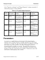
Parameters
Using Expressions as Property Values
Rules for Resolving Property Value Variables
Facts About Property Variable Resolution
Example of Property Variable Resolution
Structured Logic Design Properties
Class Property
Global Property
Inst Property
Net Property
Pin Property
Design Architect User’s Manual, V8.5_2
2-95
2-96
3-1
3-1
3-4
3-5
3-6
3-7
3-7
3-7
3-8
3-9
3-10
3-11
3-12
3-13
3-13
3-13
3-14
3-14
3-15
3-16
3-17
3-19
3-19
3-21
3-22
3-25
3-27
3-28
3-29
3-29
3-29
v
Table of Contents
TABLE OF CONTENTS [continued]
Rule Property
Frexp Property
Special Notation for CASE, FOR, and IF Property Values
Chapter 4
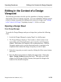
Editing in the Context of a Design
4-1
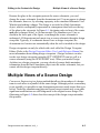
What is a Design Viewpoint?
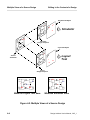
Multiple Views of a Source Design
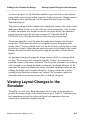
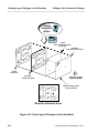
Viewing Layout Changes in the Simulator
Importing and Exporting Back Annotation ASCII Files
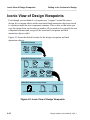
Iconic View of Design Viewpoints
Downstream Tools and Viewpoints
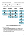
How Design Viewpoints are Created
Auto-Tool Mode
Batch (script) Mode
TimeBase Mode
Interactive Mode
Properties in the Context of a Design
Setting New Annotation Visibility
Adding Properties
Viewing Annotations vs. Evaluations
Traversing the Design Hierarchy
Merging Back Annotations to Schematic
Viewing Back Annotations
Evaluating Properties
Expressions in Back Annotation Objects
Applying Edits to the “In-Memory” Design
Reconnecting Annotations when Objects are Deleted
Chapter 5
Design Error Checking
Error Checking in Design Architect
The Check Command
Setting Up the Check Command
vi
3-29
3-30
3-30
4-1
4-3
4-5
4-8
4-10
4-11
4-13
4-13
4-14
4-14
4-14
4-15
4-15
4-16
4-17
4-18
4-19
4-19
4-25
4-28
4-30
4-31
5-1
5-1
5-3
5-5
Design Architect User’s Manual, V8.5_2
Table of Contents
TABLE OF CONTENTS [continued]
User-Defined Error Checking
Listing Status of Checks
Evaluated Design Checking
Chapter 6
Operating Procedures
Procedure Conventions
Invoking DA
From the Design Manager
From the Operating Shell
Exiting Design Architect
Obtaining Online Help
Quick Help
Reference Help
More Help Submenu
Selecting and Unselecting Objects
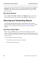
Selecting a Single Object
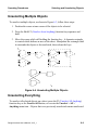
Selecting Multiple Objects
Unselecting a Single Object
Unselecting Multiple Objects
Unselecting Everything
Reselecting a Selection Set
Reopening a Selection Set
Setting the Default Selection Filter
Manipulating Graphical Objects
Moving Objects
Repeat Moving
Moving Objects Between Windows
Copying Objects
Repeat Copying
Copying Objects to a Line
Copying Objects to an Array
Copying Objects Between Windows
Resizing Instances
Grouping Objects
Design Architect User’s Manual, V8.5_2
5-5
5-7
5-7
6-1
6-1
6-2
6-2
6-4
6-4
6-5
6-5
6-5
6-6
6-6
6-6
6-7
6-8
6-9
6-9
6-10
6-10
6-10
6-11
6-11
6-11
6-12
6-13
6-13
6-14
6-15
6-16
6-18
6-19
vii
Table of Contents
TABLE OF CONTENTS [continued]
Ungrouping Objects
Reporting Groups
Deleting Objects
Pivoting and Rotating Objects
Flipping Objects
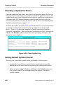
Creating a Schematic
Opening a Schematic Sheet
Setting Up the Schematic Editor
Drawing a Schematic
Checking a Schematic for Errors
Saving a Sheet and Registering a Schematic
Creating a Bus and Bus Connections
Creating and Naming a Net Bundle
Creating FOR, CASE, and IF Frames
Creating a Symbol
Opening a Symbol Editor Window
Setting Up the Symbol Editor
Drawing a Symbol Body
Adding and Naming Symbol Pins
Adding and Naming a Pin Bundle
Checking a Symbol for Errors
Setting Default Symbol Checks
Saving and Registering a Symbol
Registering Multiple Symbols to One Component Interface
Assigning Properties and Property Owners
Setting Up Property Text Attributes
Adding a Single Property
Adding Multiple Properties to the Same Object
Repeat Adding Properties to Changing Selection
Deleting Property Name/Value
Setting Property Owners
Deleting Property Owners
Listing Property Information
Changing Property Values
Changing Property Attributes
viii
6-20
6-20
6-20
6-21
6-22
6-22
6-23
6-25
6-29
6-41
6-44
6-45
6-62
6-66
6-72
6-72
6-73
6-74
6-79
6-87
6-90
6-90
6-92
6-93
6-95
6-95
6-97
6-99
6-100
6-101
6-101
6-102
6-103
6-103
6-105
Design Architect User’s Manual, V8.5_2
Table of Contents
TABLE OF CONTENTS [continued]
Reporting on Objects
Reporting on Component Interfaces
Reporting on Schematic and Symbol Objects
Reporting on Check Status
Editing DA Models in a Design Hierarchy
Creating a Functional Block
Creating a Sheet for a Symbol
Creating Additional Sheets in a Schematic
Using Off-Page Connectors
Using Portin and Portout Symbols
Editing the Sheet of a Symbol
Creating a Symbol for a Sheet
Creating a Pin List
Creating a VHDL Entity for a Symbol
Creating a Symbol From a VHDL Entity
Viewing Design Hierarchy
Adding Comment Text and Graphics
Setting Comment Text and Graphic Drawing Attributes
Creating Comment Objects on Schematic Sheets
Making a Symbol From Comment Objects
Adding a Sheet Border and Title Block
Converting Electrical Objects to Comments
Removing Comment Status
Viewing the Contents of a Sheet
Viewing a Portion of the Sheet
Viewing the Entire Sheet
Other Viewing Capabilities
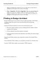
Printing in Design Architect
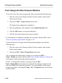
From Design Architect Session Window
From the Symbol Editor
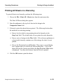
From the Schematic Editor
From the VHDL Editor
Printing All Sheets in a Hierarchy
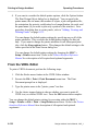
From an Operating System Shell
Printer Configuration
Design Architect User’s Manual, V8.5_2
6-107
6-107
6-109
6-111
6-112
6-112
6-113
6-115
6-115
6-116
6-117
6-117
6-119
6-120
6-120
6-121
6-121
6-122
6-123
6-124
6-125
6-126
6-127
6-127
6-127
6-128
6-128
6-129
6-130
6-131
6-131
6-132
6-133
6-134
6-134
ix
Table of Contents
TABLE OF CONTENTS [continued]
Adding, Viewing, and Deleting Panels
Using the Dialog Navigator
Editing in the Context of a Design Viewpoint
Opening a Design Sheet
Viewing Back Annotations
Editing Back Annotations
Viewing Evaluated Properties
Merging Back Annotations
Locking Schematic Sheet for Edits
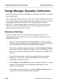
Design Manager Operation Verification
Reference Checking
Object Checking
Configuration Build
Application Invocation
Updating Parts on all Sheets in a Design
Appendix A
DA Design Checks
Schematic Sheet Checks
Required Instance Checks
Required Special Instance Checks
Required Net Checks
Required Net Bundle Checks
Required Frame Checks
Required Symbol Pin Check
Required Pin Bundle Checks
Optional Schematic Sheet Checks
Property Ownership Checks
Init Property Checks
Parameter Analysis
Expression Analysis
Instance Overlap Check
Not-dots Check
Close Dot Check
Dangling Net and Pin Checks
x
6-135
6-137
6-139
6-139
6-141
6-142
6-142
6-143
6-143
6-144
6-144
6-145
6-146
6-147
6-147
A-1
A-1
A-1
A-2
A-4
A-4
A-5
A-6
A-6
A-7
A-7
A-8
A-8
A-9
A-9
A-9
A-10
A-10
Design Architect User’s Manual, V8.5_2
Table of Contents
TABLE OF CONTENTS [continued]
Annotations
Symbol Checks
Required Symbol Pin Checks
Required Symbol Body Checks
Required Special Symbol Checks
Optional Schematic Design Checks
Pin and Port Interface Checks
Instance Check
Special Instance Checks
Net Checks
Design Architect User’s Manual, V8.5_2
A-11
A-12
A-12
A-12
A-13
A-14
A-14
A-14
A-15
A-15
xi
Table of Contents
LIST OF FIGURES
Figure 1-1. Design Architect Environment
Figure 1-2. Workstation Acts as a Computerized Drafting Table
Figure 1-3. Schematic Editor
Figure 1-4. Symbol Editor
Figure 1-5. Example of Modeling Types
Figure 2-1. Session Window Pulldown Menu Bar
Figure 2-2. Session Popup Menu and Palette
Figure 2-3. Schematic Window Pulldown Menu Bar
Figure 2-4. Symbol Window Pulldown Menu Bar
Figure 2-5. VHDL Window Pulldown Menu Bar
Figure 2-6. Design Sheet Window Pulldown Menu Bar
Figure 2-7. Component Window
Figure 2-8. Hierarchy Window
Figure 2-9. Example of a Schematic Sheet
Figure 2-10. Net Bundle/Bus and Pin Bundle Connections
Figure 2-11. Unnamed Net Connections to Pin Bundles
Figure 2-12. Ripping from a Net Bundle
Figure 2-13. Unnamed Nets Ripped from Net Bundles
Figure 2-14. Implicit Ripper Examples
Figure 2-15. Text Attributes
Figure 2-16. Symbol Structure
Figure 2-17. Symbol and Schematic Relationships
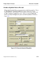
Figure 2-18. Generate Symbol Dialog Box
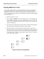
Figure 2-19. Group A Selected
Figure 2-20. Group A Closed, Group B Selected
Figure 2-21. Group A Reselected, Group B Closed
Figure 2-22. Selection Set (Sum of Groups A and B)
Figure 2-23. Composition of a Component
Figure 2-24. Component Interface
Figure 2-25. Shared Model
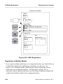
Figure 2-26. Symbol Registration
Figure 2-27. Schematic Registration
Figure 2-28. VHDL Registration
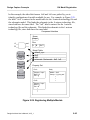
Figure 2-29. Registering Multiple Models
Figure 2-30. Instance Evaluation
xii
1-2
1-3
1-4
1-5
1-6
2-2
2-3
2-4
2-5
2-7
2-8
2-11
2-13
2-20
2-27
2-28
2-29
2-30
2-37
2-43
2-53
2-54
2-59
2-66
2-67
2-67
2-68
2-75
2-77
2-79
2-80
2-82
2-84
2-85
2-87
Design Architect User’s Manual, V8.5_2
Table of Contents
LIST OF FIGURES [continued]
Figure 2-31. File > Design Management Menu
Figure 2-32. Renaming a Component Containing a Symbol
Figure 3-1. Parameter Evaluation Rules
Figure 3-2. Property Variable Resolution Example
Figure 3-3. Status Line Showing Annotations ON
Figure 3-4. Typical FOR Frame
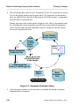
Figure 4-1. Conceptual Illustration of a Design Viewpoint
Figure 4-2. Multiple Views of a Source Design
Figure 4-3. View Layout Changes in the Simulator
Figure 4-4. Importing and Exporting ASCII Back Annotation Files
Figure 4-5. Iconic View of Design Viewpoints
Figure 4-6. Downstream Tools and Viewpoints
Figure 4-7. How Design Viewpoints are Created
Figure 4-8. “my_design” Design
Figure 4-9. “default” Back Annotation Window
Figure 4-10. “default: I$1" Window
Figure 4-11. “default: I$1" Window with Back Annotations
Figure 4-12. “default: I$2" Window
Figure 4-13. “default: I$2" Window with Back Annotations
Figure 4-14. “my_design” Design with COMP Property
Figure 4-15. “default" Back Annotation Window with I$1/I$4
Figure 4-16. “default" with Expression
Figure 4-17. “default" with Expression Evaluated
Figure 4-18. “default" with Back Annotations Enabled
Figure 4-19. “default" Back Annotation Window with Expression
Figure 4-20. “default: I$1” Window
Figure 4-21. “default" with Back Annotation Expression
Figure 4-22. “default” with Back Annotation Expression Evaluated
Figure 5-1. Symbol, Schematic, and Schematic Sheet Checks
Figure 5-2. Evaluated Design Checks
Figure 6-1. The Design Manager
Figure 6-2. Selecting a Single Object
Figure 6-3. Selecting Multiple Objects
Figure 6-4. Unselecting Multiple Objects
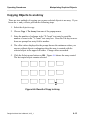
Figure 6-5. Result of Copy Multiple
Design Architect User’s Manual, V8.5_2
2-89
2-91
3-20
3-24
3-25
3-33
4-2
4-4
4-6
4-9
4-10
4-12
4-13
4-20
4-20
4-22
4-23
4-24
4-24
4-25
4-26
4-26
4-27
4-27
4-28
4-29
4-29
4-30
5-2
5-8
6-3
6-7
6-8
6-9
6-14
xiii
Table of Contents
LIST OF FIGURES [continued]
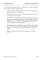
Figure 6-6. Result of Copy to Array
Figure 6-7. Open (new) Sheet Options Dialog Box
Figure 6-8. Check Sheet Log
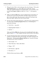
Figure 6-9. A Bus Connected to a Four-Wide Output Port
Figure 6-10. A 8x1 Bus Ripper from $MGC_GENLIB/rip
Figure 6-11. Bus Ripper Symbol
Figure 6-12. Installing a Bus Ripper
Figure 6-13. A Bus with a Connected Sub-Bus
Figure 6-14. A Bus Ripper Extracts a Range of Lines
Figure 6-15. Basic Layout
Figure 6-16. Fully Connected Bus Ripper
Figure 6-17. Choose Bundle Member Dialog Box
Figure 6-18. FOR Frame Example
Figure 6-19. Repeating Instance Example
Figure 6-20. Pintype Property Text Location
Figure 6-21. Copying Pins and Sequencing Text
Figure 6-22. IXO and OUT Pins on PLD Symbol
Figure 6-23. $MGC_PLDLIB/16hd8 Symbol
Figure 6-24. Check Symbol Log
Figure 6-25. Report Interfaces Example
Figure 6-26. Report Object Example
xiv
6-15
6-24
6-42
6-45
6-49
6-51
6-52
6-53
6-54
6-55
6-57
6-65
6-67
6-68
6-82
6-83
6-85
6-87
6-90
6-107
6-110
Design Architect User’s Manual, V8.5_2
Table of Contents
LIST OF TABLES
Table 2-1. Net, Bus, and Net Bundle Naming Examples
Table 2-2. Checking for Offpage Connectors
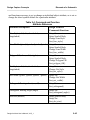
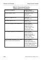
Table 2-3. Object Attributes
Table 2-4. Command and Function
Attribute Reference
Table 2-5. Schematic Objects to Symbol Objects
Table 2-6. Symbol Objects to Schematic Objects
Table 3-1. Property Structure
Table 3-2. Property Update Examples
Table 3-3. DA Objects Associated with Specific SLD Properties
Table 3-4. Structured Logic Design Properties
Table 4-1. Where Properties are Added
Table 4-2. Property Values Displayed
Table 5-1. Check Command Schematic Sheet Switches
Table 5-2. Check Command Symbol Switches
Table 5-3. Check Command Schematic Switches
Table 6-1. Available Bus Rippers in $MGC_GENLIB/rip
Table 6-2. Pin and Bus Line Connections
Design Architect User’s Manual, V8.5_2
2-26
2-34
2-44
2-45
2-72
2-72
3-3
3-17
3-26
3-26
4-17
4-18
5-3
5-4
5-4
6-49
6-57
xv
xvi
Design Architect User’s Manual, V8.5_2
About This Manual
About This Manual
Design Architect manuals provide information about the Schematic Editor, the
Symbol Editor, and the VHDL Editor.
The Design Architect User’s Manual consists of the following:
• “Overview” - Provides an overview of the editing environment and
functionality.
• “Design Capture Concepts” - Describes concepts necessary for creating and
editing a design.
• “Property Concepts” - Describes concepts related to properties associated
with design capture.
• “Editing in the Context of a Design” - Describes the concepts for editing a
schematic in the context of a design viewpoint.
• “Design Error Checking” - Discusses design checking.
• “Operating Procedures” - Provides operating procedures for various editing
tasks.
• “DA Design Checks” - Lists required and optional checks performed in
Design Architect.
For information about the documentation conventions used in this manual, refer to
the manual titled Mentor Graphics Documentation Conventions.
Design Architect User’s Manual, V8.5_1
xvii
Related Publications
About This Manual
Related Publications
The following list provides a brief overview of each of the Mentor Graphics
manuals that contain information on related topics.
Getting Started with Design Architect is for new users of Design Architect who
have some knowledge about schematic drawing and electronic design and are
familiar with the UNIX environment. This training workbook provides basic
instructions for using Design Architect to create schematics and symbols. This
document provides about 4 hours of instructions including hands-on lab exercises.
Design Architect Training Workbook provides you with a more complete
coverage of concepts and instructions on how to use Design Architect to create
schematics and symbols and how to use the Design Viewpoint Editor to create and
configure design viewpoints. This workbook features in-depth lab exercises that
will give you confidence in working with Design Architect. Some instruction on
customizing the Design Architect user interface is also include.
Design Viewpoint Editor User's and Reference Manual (DVE) contains
information about defining and modifying design configuration rules for design
viewpoints, along with latching the design. You can also add, modify and manage
back annotation data for the design from within DVE.
Design Architect Reference Manual contains information about the functions used
to create and modify schematic designs, logic symbols, and VHDL source files.
Design Viewing and Analysis Support Manual (DVAS) contains information
about functions and commands for selecting viewing, highlighting, analyzing,
reporting, protecting, grouping, syntax checking, naming, and window
manipulating capabilities. DVAS functions and commands operate within
applications such as QuickSim, QuickPath, AccuSim, QuickGrade and DVE.
Design Architect Reference Manual contains information about the functions used
to create and modify schematic designs, logic symbols, and VHDL source files.
Component Interface Browser User's and Reference Manual describes the shelllevel utility that allows you to view and edit component interfaces.
xviii
Design Architect User’s Manual, V8.5_1
About This Manual
Related Publications
AMPLE User's Manual provides overview information, flow-diagram
descriptions, explanations of important concepts, and task-oriented procedures for
customizing the common user interface and writing AMPLE functions.
AMPLE Reference Manual contains information about AMPLE statements and
functions that are common to all applications.
Common User Interface Manual describes the user interface features that are
common to all Mentor Graphics products. This manual tells how to manage and
use windows, popup command line, function keys, strokes, menus, prompt bars,
and dialog boxes.
Common User Interface Reference Manual contains information about all of the
Common User Interface functions.
DFI User's and Reference Manual contains information about the Design File
Interface, a procedural interface that allows netlist read, back annotation, and
write access to a Mentor Graphics design database.
Getting Started with QuickVHDL and VHDLwrite contains tutorials for creating,
modeling, and debugging hardware designs with Mentor Graphics QuickVHDL
and creating VHDL code from schematics using VHDLwrite. QuickVHDL is
based on IEEE Std 1076-1992, IEEE Standard VHDL Language Reference
Manual.
Design Dataport User's and Reference Manual contains information about
Design Dataport (DDP), a procedural interface that can read, write, and modify
schematic sheets and symbols.
Design Manager User's Manual provides information about the concepts and use
of the Design Manager. This manual contains a basic overview of design
management and of the Design Manager, key concepts to help you use the Design
Manager, and many design management procedures.
Design Manager Reference Manual describes the AMPLE functions that are
available in the Design Manager. This manual also describes Design Manager
shell commands.
Design Architect User’s Manual, V8.5_1
xix
Related Publications
About This Manual
Digital Modeling Guide contains basic information for designers and modelers
using the Mentor Graphics digital analysis environment. This manual can help
you make some rudimentary decisions in model or design development.
Logical Cable User's Manual provides an overview of the Logical Cable
application, introduces key concepts, and describes procedures for performing
specific tasks. This manual also describes the relationship between Logical Cable
and Physical Cable.
Logical Cable Reference Manual contains information about the functions used to
create and modify logical cabling designs.
Properties Reference Manual contains information describing all properties
created and/or used by Mentor Graphics applications for associating textual
design data with circuit elements.
xx
Design Architect User’s Manual, V8.5_1
Chapter 1
Overview
Design Architect is more than a computer-aided schematic capture application. It
is a multi-level design environment that includes: a Schematic Editor, a Symbol
Editor, and the VHDL Editor. In a multi-level design environment you can:
• Implement top-down and bottom-up design methodology
• Specify a design at different levels of abstraction, from high-level
specifications to gate-level implementation
• Specify a design with different modeling techniques
• Configure and manage different design descriptions to explore alternate
design implementations
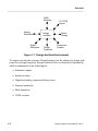
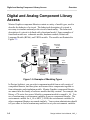
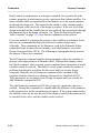
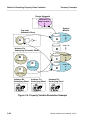
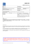
As Figure 1-1 indicates, Design Architect is the center of activity for most Mentor
Graphics design processes. Design Architect lets you create and edit logical
designs that are used by downstream processes such as: board design, IC and
PCB layout, and analog and digital simulation. Many applications return design
information to Design Architect in the form of back annotation values. These
values can then be edited in the context of the design viewpoint (a description of
design viewpoints begins on page 4-1) by Design Architect and, optionally,
merged into the original source design. This cycle of creating a logical design,
passing it to a downstream application for processing, and then passing new
updated property values back to Design Architect for editing is a common design
process.
Design Architect User’s Manual, V8.5_1
1-1
Overview
VHDL
Modeling
Analog
Simulation
Digital
Simulation
IC & PCB
Layout
Board
Design
Design
Architect
Component
Creation
Design
Synthesis
Figure 1-1. Design Architect Environment
To support not only the creation of logical designs, but the editing of a design with
respect to a design viewpoint, Design Architect offers a collection of functionality
which is summarized in the following list:
• Schematic capture
• Symbol creation
• Digital and analog component library access
• Property annotation
• Back annotation
• VHDL creation
1-2
Design Architect User’s Manual, V8.5_1
Overview
Schematic Capture
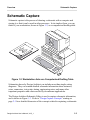
Schematic Capture
Schematic capture is the process of drawing a schematic with a computer and
storing it so that it can be used in other processes. In its simplest form, you can
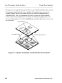
think of your workstation, shown in Figure 1-2, as a computerized drafting table.
Figure 1-2. Workstation Acts as a Computerized Drafting Table
Schematics drawn by Design Architect can include more than simple wiring
diagrams. They can contain detailed schematic information about instances,
wires, connectors, test points, timing, engineering notes, and many other
important properties and values needed by downstream applications.
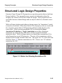
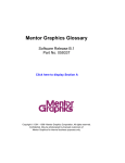
The Design Architect Schematic Editor is used to capture schematic information,
and is shown in Figure 1-3. Refer to "Design Capture Concepts" starting on
page 2-1 for a detailed discussion of the concepts related to capturing a schematic.
Design Architect User’s Manual, V8.5_1
1-3
Schematic Capture
Overview
.
Design Architect
MGC
Sel: 0
File
Edit
Setup
Miscellaneous
Libraries
Check
Report
View
( W | dae ) ( my_dffl | schematic | sheet1) ( ) ( )
Help
( 1.1572, 1.8591 )
Schematic#1 my_dff sheet1
Active Symbol
Window
There is no active symbol
schematic_add_route
(0,0)
Origin
Schematic
Palette
SESSION
ADD/ROUTE
TEXT
DRAW
DELETE
UNDO
MOVE
COPY
UNSELECT
ALL
SET SELECT
FILTER
LIBRARY
CHOOSE
SYMBOL
ADD
ADD BUS
Context
Window
F3
F9
F1
F2
F4
F5
F6
F7
F8
F10
F11
F12
Select Are Unselect A Add Wire Popup Me Place Sym Set Grid S
Sel Txt & View Area Setup Ses Pulldown M Command Pop Windo
S
Select Ver Unselect A Add Bus
Chg Text V View All
Read File Close Win
Add Prope Connect A
C Open Up Open Dow
Copy
Reopen Se Move
Reselect Check She
A
i Version 1 of component “/users/home/training/da_n/card_reader/my_dff"”has been written
Message indicating the creation of a new component
Figure 1-3. Schematic Editor
1-4
Design Architect User’s Manual, V8.5_1
Overview
Symbol Creation
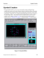
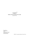
Symbol Creation
Design Architect allows you to create and modify analog and digital logic
symbols that can be used in other Design Architect schematic designs. Symbols
can represent basic design elements such as logic gates, transistors, off-the-shelf
components, custom ICs, or a complete board design that represents a portion of
the total design effort. The Design Architect Symbol Editor is used to create
symbols, and is shown in Figure 1-4. For more information about symbol
creation, refer to "Elements of a Symbol", starting on page 2-52 in this manual.
Design Architect
MGC
File
Sel:
( W | dae ) ( dff | dff ) ( ) ( )
0+
Edit
Setup
Miscellaneous
Check
Report
View
Help
(4.0189, -0.7736)
IN
IN
Symbol#1
dff
PRE
D
IN
Q
OUT
CLK
0
0
IN
QB
OUT
0
CLR
0
There is no active symbol
symbol_draw
SESSION
TEXT
DRAW
DELETE
UNDO
MOVE
COPY
UNSELECT
ALL
SET SELECT
FILTER
F0
F1
F2
F3
F4
F5
F7
F6
F8
Add Arc
Set Grid Sn Sel Txt & M View Area
Pulldown M Select Area Unselect All Add Polylin Popup Menu
s Add Propert
Chg Text Va View All
Add Pin
Select Pin Unselect Ar
Reselect c Check Symb
Reopen Sel
Move
Copy
a
F9
Setup Sessi
Figure 1-4. Symbol Editor
Design Architect User’s Manual, V8.5_1
1-5
Digital and Analog Component Library Access
Overview
Digital and Analog Component Library
Access
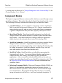
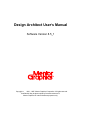
Mentor Graphics component libraries contain a variety of model types, used to
describe the behavior of a circuit. The behavioral description of a circuit is
necessary to simulate and analyze the circuit's functionality. The behavioral
description of a circuit is defined with a functional model. Some examples of
functional models are: schematic models, hardware models, Behavioral
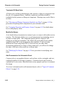
Language Models (BLMs), and VHDL models. The models are illustrated in
Figure 1-5.
D
PRE
Schematic
Model
Symbol
Model
Q
CLR
CLK
_Q
Behavioral
Language
Model
IF CLKRISE THEN
IF PRE and CLR = 1
THEN
IF D = 0 THEN
Q = 0 and QBAR = 1
Hardware
Modeling
VHDL
Model
PROCESS (d0, d1, sel)
BEGIN
IF sel = '0' THEN
q <= d1;
ELSE
q <= d0;
END IF;
END PROCESS;
Simulation
Figure 1-5. Example of Modeling Types
In Design Architect, you can select component models from a wide variety of
component libraries, and then place and connect these components together to
form schematics and simulation models. Mentor Graphics component libraries
are named after the family of software models that they contain. For example, the
library of 74-series low-power Schottky component models is named ls_lib. You
use a location map or environment variables to access component libraries. The
environment variable for ls_lib is MGC_LSLIB; the environment variables for
other component libraries are named similarly. Your system administrator should
tell you where to find a location map and how to set your environment variables.
1-6
Design Architect User’s Manual, V8.5_1
Overview
Digital and Analog Component Library Access
Location maps are discussed in "Design Management with Location Maps" in the
Design Manager User's Manual.
Component Models
The logical component libraries contain models which are created through various
modeling techniques. The models describe the logical functionality of the circuit.
The following list briefly describes the different types of models available.
• gen_lib Primitives. A set of primitive components, such as simple logic
gates, is provided in the generic library gen_lib. Generic components are
non-technology specific, and are used to create other library components.
A generic component has delay and other property values preset to zero.
• Sheet-Based Models. Sheet-based models (schematics) are built with
Design Architect and contain instances of primitive parts and other sheetbased models. Sheet-based models use timing information (properties)
added directly to the schematic sheet, instead of technology files.
• QuickPart Schematics. QuickPart schematic models are compiled from a
Design Architect schematic. A QuickPart contains the schematic, a
description of the circuit's functionality, and a technology file that describes
the timing information. QuickPart schematic models occupy less disk
space and simulate faster than sheet-based models.
• QuickPart Tables. QuickPart tables are truth tables representing the
functionality of a device. You can use Mentor Graphics applications to
compile the table into a binary form usable by other downstream
applications. A device modeled with a QuickPart table can be used as a
primitive on a sheet-based model or on a QuickPart schematic model. See
the QuickPart Model Development Manual for more information about
QuickPart Tables.
• Behavioral Language Models. Behavioral Language Models (BLMs) are
Pascal or C programs that simulate the function of complex devices. A
BLM can be used as a primitive, and can also be used to model at a high
level of abstraction. The program that describes the device can contain
timing information for the device, as well as a functional description. If
Design Architect User’s Manual, V8.5_1
1-7
Property Annotation
Overview
timing information for the device is not embedded within the BLM, a
technology file must supply the timing information. Refer to the
Behavioral Language Model (BLM) Development Manual for detailed
information about BLMs.
• VHDL Models. VHDL models describe highly complex circuits or
systems at high levels of abstraction. Typically, you would use a VHDL
model to define an ASIC system, or board whose function is too complex to
model using an alternative modeling technique. VHDL models are written
using System-1076 or QuickVHDL. Refer to the System-1076 Design and
Model Development Manual or the QuickVHDL User's and Reference
Manual for detailed information about developing VHDL models.
• Hardware Models. Hardware models supply the functionality of a device
by way of a Mentor Graphics Hardware Modeler, such as LM-family
models. A hardware modeler is a network resource that applies stimulus to
an actual IC to determine its behavior, and then feeds this information back
to the digital simulation. Refer to the LM-family User's Manual for
information about hardware models.
Property Annotation
Property annotation is the process of adding design information called
"properties" to schematics and symbols. Most design applications, including
analysis and layout, have certain design requirements that must be met before the
design can be implemented. Downstream applications require that correct
property values be added to the design for processing. These properties describe
characteristics of the design which are not identifiable from the schematic alone.
It is very important to know which properties must be assigned in Design
Architect so that the proper information is transferred to a particular down-stream
application. For more information about properties refer to "Property Concepts",
starting on page 3-1, and to the Properties Reference Manual.
1-8
Design Architect User’s Manual, V8.5_1
Overview
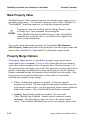
Back Annotation
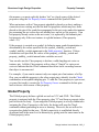
Back Annotation
Back annotation is the process of attaching new or changed property values,
created in a downstream application, to the original schematic sheet. For
example, after a circuit is physically placed on a PCB or IC, new time delay
property information is made available. The new property values pertaining to
this new time delay information are associated with the design viewpoint, and a
more accurate simulation of the circuit can then be done using these updated
values. More information about design viewpoints and the concepts related to
editing back annotation data in the context of a design begins on page 4-1.
VHDL Creation
Design Architect creates VHDL models using the VHDL Editor and System1076 or Quick VHDL compiler. The VHDL Editor lets you create and edit
VHDL text files by inserting and expanding VHDL language constructs. The
compiler built into the VHDL Editor allows instant compilation of models.
For further information about creating VHDL models, refer to the System-1076
Design and Model Development Manual or the QuickVHDL User's and Reference
Manual.
Design Architect User’s Manual, V8.5_1
1-9
VHDL Creation
1-10
Overview
Design Architect User’s Manual, V8.5_1
Chapter 2
Design Capture Concepts
The following topics introduce you to the Design Architect environment and
define important concepts necessary to create designs with Design Architect.
Design Architect Environment
You have access to three editors within the Design Architect environment: (1) the
Schematic Editor to create schematics, (2) the Symbol Editor to create userdefined symbols, and (3) the VHDL Editor to create VHDL models. The three
editors are accessible from a common Design Architect Session window. Each
editor operates in its own window within the Session window. Multiple windows
for each editor can be open at the same time.
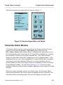
Design Architect Session Window
The Design Architect Session window can be invoked from the Design Manager
Tool window by double-clicking on the Design Architect icon. After the Design
Architect Session window is activated, Design Architect editing windows can be
opened using the Design Architect Session popup menu items, function keys, or
palette icons. The softkey labels near the bottom of the window show the Session
function key descriptions.
Design Architect User’s Manual, V8.5_1
2-1
Design Architect Environment
Design Capture Concepts
The Design Architect Session window menu bar is illustrated in Figure 2-1. The
menu bar always contains the names of the pulldown menus for the current active
window. You access pulldown menus by pressing and holding the Select (left)
mouse button on the menu name.
Design Architect
MGC
File
Setup
Help
Figure 2-1. Session Window Pulldown Menu Bar
The Session window pulldown menus include items that let you open and position
windows, change window attributes, save and restore userware configurations,
print text and graphics, find components, open a Notepad window, and access
online help.
Items in the Session window popup menu let you open edit windows to view,
create, and modify symbols, schematic sheets, schematic sheets in the context of a
design viewpoint, and VHDL text files. You display this popup menu by moving
the location cursor inside the desired window and pressing and holding the Menu
(right) mouse button. To choose an item from the menu, move the mouse (with
the Menu button still depressed) to slide the cursor down the menu; when the
desired item is highlighted, release the mouse button. These items, except for
MGC, are also available in the Session File pulldown menu, and in the Session
palette.
2-2
Design Architect User’s Manual, V8.5_1
Design Capture Concepts
Design Architect Environment
The Session popup menu and palette are shown in Figure 2-2.
Session
Open Sheet ...
Open Design Sheet ...
Open Symbol ...
Open VHDL ...
Open Source Code ...
Find Component ...
MGC
session_palette
FIND
COMP
OPEN
OPEN
SHEET
SYMBOL
DESIGN
OPEN
VHDL
SHEET
HIER
COMP
ARCHY
WINDOW
WINDOW
TRANSETUP
SESSION
SCRIPT
Figure 2-2. Session Popup Menu and Palette
Schematic Editor Window
A Schematic Editor window can be opened from the Design Architect Session
window by executing the Session > Open Sheet popup menu item, the
File > Open > Sheet pulldown menu item, or clicking on the Open Sheet icon in
the Session palette menu, or pressing the F1 (Open Sheet) function key, or typing
the command or function in the popup command line. All of these methods
display the Open Sheet dialog box, prompting you for a component name. If the
component does not exist, a new component is created with the name you supply.
You can also invoke the Schematic Editor on an existing schematic sheet by
double-clicking the Select (left) mouse button on a schematic or sheet icon in the
Design Manager window. See the Design Manager User's Manual for more
information about invoking a Mentor Graphics application from within the Design
Manager.
When you open a schematic window, the softkeys show the Schematic Editor
function key definitions, the Session palette and popup menu are replaced by the
schematic palettes and popup menus, the menu bar displays the names of the
Design Architect User’s Manual, V8.5_1
2-3
Design Architect Environment
Design Capture Concepts
schematic pulldown menus, and a status line is displayed beneath the menu bar.
The Schematic Editor menu bar and status line are shown in Figure 2-3. The
status line provides information about the design object in the window and current
editing status.
Design Architect
MGC
File
Sel:
( W | dae ) ( my_des | schematic | sheet1 ) (inv | inv) ( )
0+
Edit
Setup
Miscellaneous
Libraries
Check
Report
View
Help
(4.0189, -0.7736)
Figure 2-3. Schematic Window Pulldown Menu Bar
The palettes, popup, and pulldown menus supply you with the commands
necessary to create a schematic. The more commonly used Schematic Editor
window palettes and menus include commands to:
• Instantiate components
• Create and modify properties
• Create and modify nets
• Create and edit comment graphics and text
• Set up templates for creating nets, comments, property text, grids, pages
• Edit objects (moving, copying, deleting, connecting)
• Report on sheet objects' status
• View a sheet
• Check schematic sheets for errors
• Save and register schematics
• Access online help
2-4
Design Architect User’s Manual, V8.5_1
Design Capture Concepts
Design Architect Environment
The Schematic Editor has added functional capabilities when editing a schematic
sheet in the context of a design viewpoint. This mode of editing is described
starting on page 4-1.
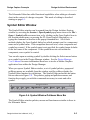
Symbol Editor Window
The Symbol Editor window can be opened from the Design Architect Session
window by executing the Session > Open Symbol popup menu item or the File >
Open > Symbol pulldown menu item, or by clicking on the Open Symbol icon in
the Session palette menu, or pressing the F5 (Open Symbol) function key, or
typing the command or function in the popup command line. All of these
methods display the Open Symbol dialog box which prompts you for a component
name and a symbol name. If the component does not exist, a new component and
symbol are created. If the symbol name is not specified, the symbol name defaults
to the leaf name of the component. If the symbol does not exist within the
component, a new symbol is created.
You can also open an existing symbol by double-clicking the Select mouse button
on a symbol icon in the Design Manager window. See the Design Manager
User's Manual for more information about how to invoke a Mentor Graphics
application from within the Design Manager.
When you open a Symbol Editor window, a set of symbol palettes, popup and
pulldown menus are available from the window, and the softkeys display the
Symbol Editor function key definitions. The Symbol Editor menu bar and status
line are shown in Figure 2-4. The palettes, popup and pulldown menus, and
function keys supply you with the commands necessary to create and edit a
symbol.
Design Architect
MGC
File
Sel:
( W | dae ) ( dff | dff ) ( ) ( )
0+
Edit
Setup
Miscellaneous
Check
Report
View
Help
(4.0189, -0.7736)
Figure 2-4. Symbol Window Pulldown Menu Bar
The Symbol Editor window palettes, menus and functions are similar to those in
the Schematic Editor.
Design Architect User’s Manual, V8.5_1
2-5
Design Architect Environment
Design Capture Concepts
The more commonly used Symbol Editor commands let you:
• Create symbol body graphics
• Set up templates for creating comments, property text, grids, pages
• Edit objects (moving, copying, deleting)
• Report on symbol objects' status
• View a symbol
• Add pins and properties to the symbol
• Create and edit non-instantiable comments
• Check a symbol for errors
• Save and register a symbol
• Access online help
VHDL Editor Window
The VHDL Editor window can be opened from the Design Architect Session
window by executing the Session > Open VHDL popup menu item, the
File > Open > Symbol pulldown menu item, or by clicking on the Open VHDL
icon in the Session palette menu, or pressing the F6 (Open VHDL) function key.
All of these methods display the Open VHDL dialog box prompting you for a
VHDL filename. If the VHDL filename does not exist, a new VHDL file is
created with the filename you supply.
The VHDL Editor can also be invoked on an existing VHDL file by doubleclicking the Select mouse button on a VHDL text icon in the Design Manager
window. See the Design Manager User's Manual for more information about
invoking a Mentor Graphics application from within the Design Manager.
2-6
Design Architect User’s Manual, V8.5_1
Design Capture Concepts
Design Architect Environment
When you open a VHDL window, a set of VHDL editing popup menus and
pulldown menus are available from the VHDL editing window, and a new list of
items is displayed in the menu bar. The VHDL menu bar is shown in Figure 2-5.
Design Architect
MGC File Edit Search Templates Compile View Options Help
Figure 2-5. VHDL Window Pulldown Menu Bar
These popup and pulldown menus supply you with the commands necessary to
create and compile VHDL models.
The VHDL editor window includes commands to:
• Create and modify VHDL text
• Expand and insert VHDL templates
• Compile VHDL text
• Access online help
The VHDL Editor palette and function keys also have some of the more common
commands for editing VHDL models.
Design Sheet Window
A Design Sheet window can be opened from the Design Architect Session
window by executing the Session > Open Design Sheet popup menu item, the
File > Open > Design Sheet pulldown menu item, or by clicking on the Open
Design Sheet icon in the Session palette menu, or by pressing the F3 (Open
Design Sheet) function key, or by typing the command or function in the popup
command line. All of these methods display the Open Design Sheet dialog box
prompting you for a component name and a viewpoint name.
Design Architect User’s Manual, V8.5_1
2-7
Design Architect Environment
Design Capture Concepts
A component and a schematic sheet must exist to invoke on a design sheet. If you
do not specify a viewpoint name, a new viewpoint is created with the name
"pcb_design_vpt". The Design Sheet can also be invoked on an existing design
by double-clicking with the Select mouse button on a design viewpoint icon in the
Design Manager window.
When you open a design sheet window, you get the same set of popup and
pulldown menus as in the Schematic Editor window; while editing in the context
of a design viewpoint, an additional set of functions become accessible. The title
area of the window shows the name of the schematic sheet, as in the Schematic
Editor, with "(Design Context)" appended to the name. The Schematic Editor
pulldown menus, the status line, and the title area of the edit window are shown in
Figure 2-6. The status line includes the name of the viewpoint.
Design Architect
MGC
File
Edit
Setup
Miscellaneous
Libraries
Check
Sel: 0 ( W | DAe ) ( dff | schematic | sheet1 ) (inv/inv) ( dff/pcb_design_vpt )
Report
View
Help
(4.0189, -0.7736)
Schematic#1 dff sheet1 (Design Context)
Figure 2-6. Design Sheet Window Pulldown Menu Bar
These palettes, function keys, popup, and pulldown menus supply you with the
commands necessary to edit a schematic, plus commands to edit the schematic in
the context of a design viewpoint.
The Design Sheet window includes all the schematic editing commands, plus
commands to:
• View and edit back annotations
• Create back annotations
• View evaluated and unevaluated properties
• Merge back annotations to schematic sheet
2-8
Design Architect User’s Manual, V8.5_1
Design Capture Concepts
Design Architect Environment
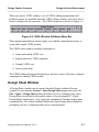
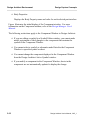
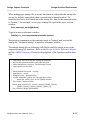
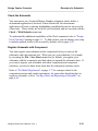
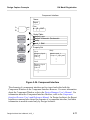
Component Window
The Component Window allows you to view or edit detailed information about a
component. Some of the things you can do in the Component Window are:
• List the Part Interfaces for Models, Labels, Pins, Pin Properties, and Body
Properties for a given component
• Register and unregister component models
• Add/delete or edit labels for a component.
• Show all objects contained by the component, and optionally filter out
objects depending on type.
You invoke the Component Window using the MGC pull down menu or from the
session window palette. A window appears that is divided into four distinct
information list areas. Each list area has a separate popup menu. The four list
areas are:
• Component Information
Displays an indented list of the component and its contents. Icons next to
items indicate the object type. Multiple components can be shown at one
time. Use the setup form to filter the types you wish to view.
• Models
Displays all registered models for each part interface selected in the
component list area. Labels are shown indented underneath the model
name. Models are distinguished for a given component by the gray header
bar.
• Pins
Displays Pin names and properties for each selected part interface.
Design Architect User’s Manual, V8.5_1
2-9
Design Architect Environment
Design Capture Concepts
• Body Properties
Displays the Body Property name and value for each selected part interface.
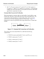
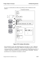
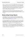
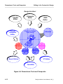
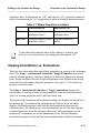
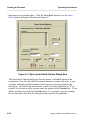
Figure illustrates the initial display of the Component window. For more
information on the Component window, refer to the Design Manager User's
Manual.
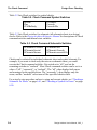
The following restrictions apply to the Component Window in Design Architect:
• If you are editing a symbol in a Symbol Editor window, you cannot make
model registration or label changes to the component that contains the
symbol in the Component Window.
• You cannot select a symbol or schematic model listed in the Component
Window to open the symbol or sheet.
• You cannot change the component displayed in the Component Window
from the Design Architect Active Symbol window.
• If you modify a component in the Component Window, sheets in the
component are not automatically updated to display the change.
2-10
Design Architect User’s Manual, V8.5_1
Design Capture Concepts
Design Architect Environment
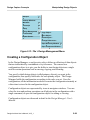
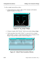
Component Window
Component Information
Registered Model Info
C
$TRAINING/da_n/my_df
my_dff (Default)
ANSI
my_dff
part
schematic
schem_id
sheet1
schemaitc2
schem_id
sheet1
my_dff [$TRAINING/da_n/card_reader/my_df]
Graphical Models
$TRAINING/da_n/card_reader/my_dff/my_dff
$TRAINING/da_n/card_reader/my_dff/ANSI
default_sym
Functional Models
$TRAINING/da_n/card_reader/my_dff/schematic
schematic
$schematic
default
$TRAINING/da_n/card_reader/my_dff/schematic2
schematic2
$schematic2
Pins
my_dff [$TRAINING/da_n/card_reader/my_dff]
D
CLK
PRE
CLR
Q
QB
Body Properties
my_dff [$TRAINING/da_n/card_reader/my_dff]
qfall = 0
qbfall = 0
qrise = 0
qbrise = 0
model = schematic
Figure 2-7. Component Window
Design Architect User’s Manual, V8.5_1
2-11
Design Architect Environment
Design Capture Concepts
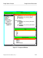
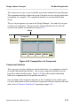
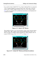
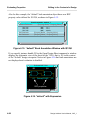
Component Window
The Component Window allows you to view your design's configuration and
component information without having to exit the application. It also allows you
to:
• Display a component hierarchy in the context of a specific viewpoint
• Display design hierarchies that are not dependent on viewpoints
• Display instance information for a given component
• Display the path to a single instance
• Display the hierarchy as an indented list or a graphical tree
• Probe other applications.
• Display the value of a specified property rather than the instance name next
to component in the hierarchy listing.
Because you look at a physical or logical hierarchy listing rather then looking at a
file system, you get information concerning the instances names, property values,
object designations and model information.
You access this Hierarchy Window using the MGC Pulldown menu or the session
window palette.
2-12
Design Architect User’s Manual, V8.5_1
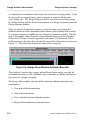
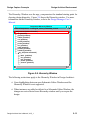
Design Capture Concepts
Design Architect Environment
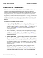
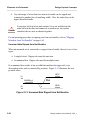
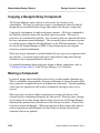
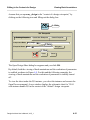
The Hierarchy Window uses the mgc_component as the standard starting point for
showing design hierarchy. Figure 2-8 shows the Hierarchy window. For more
information on the Hierarchy window, refer to the Design Manager User's
Manual.
Component Hierarchy Window
Current Component: ...training/da_n/card_reader/add_convert
add_convert (schm:schematic)
rip (primitive)
ground (primitive)
74259 (primitive)
vcc (primitive)
res.alt (primitive)
portin (primitive)
inv (primitive)
and2 (primitive)
portout (primitive)
74ls161a (primitive)
my_dff (schm:schematic)
latch (primitive)
inv (primitive)
buf (primitive)
portin (primitive)
portout (primitive)
Figure 2-8. Hierarchy Window
The following restrictions apply to the Hierarchy Window in Design Architect:
• Cross-highlighting between open Schematic Editor Windows and the
Hierarchy Window is not supported.
• When instances are added or deleted in a Schematic Editor Window, the
changes are not reflected in an Hierarchy window until you reopen the
design.
Design Architect User’s Manual, V8.5_1
2-13
Design Architect Environment
Design Capture Concepts
Integrated Editing Environment
Design Architect provides an integrated schematic and symbol editing
environment, which includes an integrated command set, multiple window
viewing and editing, and the capability of editing a symbol in-place on a
schematic sheet.
Integrated Command Set
The Design Architect editors share a common, integrated command set. Within
an integrated command set, commands performing the same function are used by
all the editors. For example, the Add Circle command is used in both the
Schematic and Symbol Editors, and calls the same function, $add_circle(). In
either application, a graphic circle is drawn. Within the Symbol Editor, the circle
is interpreted as symbol graphics, and within the Schematic Editor, it is
interpreted as comment graphics. Refer to the Design Architect Reference
Manual for descriptions of all commands and functions used within both
Schematic and Symbol Editors.
Multiple Window Viewing and Editing
In Design Architect you can operate in a multi-window environment, giving you
the capability of having multiple edit or view windows displayed on the same
design. Each window must be opened in either edit or view mode. Having
multiple views of the same sheet or symbol allows changes made in one window
view to be displayed concurrently in the other window views.
Only one window may be open in edit mode for any one sheet or symbol.
However, different sheets in a schematic can be open for concurrent editing.
Also, in a multi-window environment, graphics can be copied back and forth
between windows. For example, graphics generated in a schematic or symbol
window can be moved to other schematic or symbol windows. Refer to "InterWindow Copy and Move" on page 2-72 for more information about inter-window
copy and move.
2-14
Design Architect User’s Manual, V8.5_1
Design Capture Concepts
Design Architect Environment
Editing a Symbol In-Place on a Schematic
In addition to editing a symbol in a separate window environment, you can edit
symbols directly on a schematic sheet. This is called symbol edit in-place. This
methodology is useful for top-down design when creating and modifying
functional blocks.
When you edit a symbol directly in the context of its instance on the schematic,
the schematic sheet circuitry is still visible (grayed out) while you edit the symbol
contents. Errors, such as mismatching the symbol pins with the connecting nets or
using incorrect pin spacing, are avoided because the symbol can be modified in
the position of its instance-to-be on the schematic. Refer to page 2-60 for more
information about editing a symbol in place.
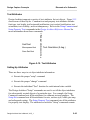
DA Startup Files
When you are familiar with your DA environment, you can use startup files to
define your own menus, keys, strokes, or any functions used to initialize your
working environment. Startup files are written in the AMPLE language, and have
access to the full capability of DA functions within a specific window scope.
Before you begin writing DA startup files, refer to the AMPLE User's Manual for
information about how to write AMPLE macros and additional startup file
examples. Refer to the Customizing the User's Interface Manual for instructions
for customizing your user interface.
For information about scopes and additional methods of introducing custom
userware such as libraries to Design Architect, refer to Appendix A in the Design
Architect Reference Manual.
In DA, a startup file can be specified for the initial opening of a DA Session
window, Schematic Editor window, Symbol Editor window, and VHDL Editor
window.
Design Architect User’s Manual, V8.5_1
2-15
Design Architect Environment
Design Capture Concepts
DA supports four levels of startup files:
• Site-specific: $MGC_HOME/shared/etc/cust/startup/name.startup
• Workstation-specific: $MGC_HOME/etc/cust/startup/name.startup
• User-specific: $HOME/mgc/startup/name.startup
• Component-specific: pathname to startup file specified in the Open Sheet,
Open Symbol, and Open VHDL dialog boxes.
In DA, "name" can represent "da_session", "schematic", "symbol", and "vhdl" for
each respective DA environment. $HOME is the value of the HOME
environment variable for your shell, typically your login directory.
$MGC_HOME is the value of the MGC_HOME environment variable that
specifies the location of your Mentor Graphics software. $MGC_WD is the value
of the MGC_WD environment variable that specifies the current working
directory.
All applications search for startup files and execute them in the following order:
1. Site-specific startup files, if they exist.
2. Workstation-specific startup files, if they exist.
3. User-specific startup files, if they exist.
Component-specific startup files are executed when a pathname is specified in the
Startup File Path text box for the dialog box that opens a symbol, sheet, or a
VHDL document. A default value for this pathname can be specified with the
$set_environment_dofile_pathname() function.
2-16
Design Architect User’s Manual, V8.5_1
Design Capture Concepts
Design Architect Environment
When debugging a startup file, be aware that function calls within the startup file
are not, by default, transcribed when executed from a startup location. To
transcribe the lower-level functions in the startup file, first set the transcript mode
to "bottom". For example, to test a new startup file, type in the active session
window:
$set_transcript_mode(@bottom)
Type in an active schematic window:
$dofile(your_home/mgc/startup/schematic.startup)
The previous commands set the transcript mode to "bottom" and execute the
startup file "schematic.startup" in an active schematic window.
The sample startup files in following code blocks could be placed in any of the
supported startup file locations. Refer to the Design Architect Reference Manual
and the AMPLE Reference Manual for descriptions of the functions used in these
files.
//
//
//
//
//
//
//
//
//
//
//
This startup file sets up the DA Session environment
and sets the selection model to individual selection
rather than additive selection. The following Session
setup options are specified:
Mouse button click speed = average
Input device = mouse
Window layout = quadrant tiling
Visible: menu bar, window title, message area, palette,
status line, softkey area, Active Symbol window.
Not visible: Context window.
$form_setup_session(125, "mouse", @quad, [@true], [@true],
[@true], [@true], [@true], [@true], [@true], []);
$set_selection_model(@individual);
Design Architect User’s Manual, V8.5_1
2-17
Design Architect Environment
Design Capture Concepts
The next example, sets up the editing environment in the Schematic Editor, then
sets the default sheet checks.
//
//
//
//
//
//
//
//
//
//
//
//
//
//
//
//
//
//
This startup file sets net, property text, and comment
attributes, then sets default sheet checks.
Net attributes:
width = p1, dotted line, orthogonal mode = off,
snap angle = 44.9, snap = on, dotsize = 0.025,
dotstyle = square, junction dots at rippers,
closedots displayed, bus_width = p3, autoroute = on,
autoripper = on, ripper_symbol = "$MGC_GENLIB/rip", "1X1"
Property Text attributes:
font = "stroke", ht=0.1875, left-bottom justification,
horizontal, transparent, visible
Comment attributes:
style = shortdash, width = p3, fill = clear,
font = "stroke", height = 0.1875,
left-bottom justification, horizontal, transparent
$setup_net(@p1, @dot, @off, 44.9, @on, 0.025, @square, @on,
@on, @p3, @on, @on, "$MGC_GENLIB/rip", "1X1");
$setup_property_text("stroke", 0.1875, @left, @bottom, 0,
@on, @on);
$setup_comment(@shortdash, @p3, @clear, "stroke", 0.1875,
@left, @bottom, 0, @on);
// The following list shows the default sheet checks set by
// the next function:
// checkfile not saved, report in window and transcript
// no user-defined checks
// errors and warnings reported for: instances,
//
special symbols, nets, frames, expressions, pins,
//
notdots, closedots, dangling nets and pins
// errors only reported for: parameters, property owners,
//
overlapping instances,
$setup_check_sheet("da_check_file", @nofile, @window,
@transcript, "", void, @all, @all, @all, @all,
@errorsonly, @all, @all, @errorsonly, @errorsonly,
@all, @all, @all, @nocheck);
2-18
Design Architect User’s Manual, V8.5_1
Design Capture Concepts
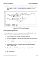
Elements of a Schematic
Elements of a Schematic
Schematics are created in the Design Architect Schematic Editor window. A
schematic is more than a simple schematic drawing. It contains additional
schematic capture information about components, wiring, connectors, test points,
timing, and engineering notes, which can be used by downstream applications.
A schematic is a graphical and behavioral description of a circuit. Schematics are
built by combining and connecting electrical objects together. Schematic sheets
can also be annotated with comment graphics and text which have no electrical
meaning.
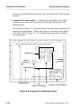
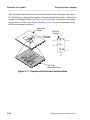
A schematic can contain the following elements:
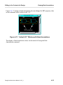
• Instances of Logical Symbols. Instances of logical symbols can represent
anything from a simple logic function to a complete integrated circuit.
Instances of logical symbols, as illustrated in Figure 2-9, are labeled as U11
and U30. Refer to page 2-52 for a more detailed discussion of how to
create logical symbols.
• Nets. A graphical net is a pin-to-pin wiring connection between instances
on a schematic sheet. In Figure 2-9, the instances of logical symbols U11
and U38 are connected to each other by a net. Refer to page 2-22 for more
information about nets.
• Property Name/Value. A property name is the label for a property, much
like a variable name is a label for a variable in a programming language.
The property value is the value associated with the name. The combination
property name/value is attached to different objects in a schematic to supply
more information about the object. For example, the rise time for a pin is
specified by a value (for example, "10, 20, 30") of a property name "Rise",
attached to that pin.
Some property values are displayed on the sheet. Net property values
FINISH and COMPARE are displayed in Figure 2-9. Other properties
attached to objects on a schematic sheet are not visible on the screen. You
control the visibility of the property value. There are several important
Design Architect User’s Manual, V8.5_1
2-19
Elements of a Schematic
Design Capture Concepts
concepts to understand about properties; they are discussed in detail starting
on page 3-1.
• Comment Text and Graphics. Comment text and graphics, also called
comments, have no electrical meaning, but add other information to the
schematic sheet.
For example, in Figure 2-9, the border of the schematic sheet is created with
comment text and graphics. Many other forms of comments can be added
to the sheet. Refer to page 2-38 for a detailed discussion about comment
text and graphics.
1
2
3
4
5
6
7
8
$MGC_HOME/shared/training/qsim82nwp/parts/models/fusefile.jed
A
A
PLS155
11
1
B
COUNT(11:0)
2
OSC
3
8
4
7
5
6
74LS08
C
9
U30
CK
_OE
P2
P3
P4
P5
9
U11
FINISH
8
6
P6
P7
P8
P9
P12
P13
P18
P19
P14
P15
P16
P17
7
5
8
4
9
5
12
4
13
3
18
2
19
1
14
B
0
15
PULSE
16
17
LATCH
10
D
D
COMPARE(7:0)
Engineer:
john smith
Drawn by:
john smith
Mentor Graphics
8005 SW Creek Rd.
Wilsonville, OR
R&D CHK:
TITLE:
design_2397
DOC CTRL CHK
E
Size:
D
E
MFG CTRL CHK
Changed by:
john smith
1
2
3
Property Values
C
Date Changed:
Monday, August 31, 1992
4
QA CHK:
Time:
REV
B
1:46:33 pm
5
6
Net
Drawing Number: Page:
1
24
7
8
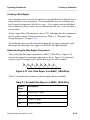
Comment Text and Graphics
Instances of Symbols
Figure 2-9. Example of a Schematic Sheet
2-20
Design Architect User’s Manual, V8.5_1
Design Capture Concepts
Elements of a Schematic
Electrical Connectivity
Electrical objects are graphically placed and annotated on a schematic sheet to
form an electrical connectivity model. The proper connection of nets, pins,
instances, and special instance connectors creates the functional implementation
of the circuit.
Electrical connectivity for a design is further defined by adding properties to these
objects. For example, the addition of a "Rise" or "Fall" property owned by a pin
further defines the electrical quality of the pin connection. This is also the case
when a "Net" property defines whether the net is a bus or a wire. Properties are
discussed in detail starting on page 3-1.
Electrical Objects Represented on a Schematic
Many types of electrical objects make up a schematic. The objects in the
following list are used to build the schematic. When placed properly on the sheet,
each electrical object forms a connection to another electrical object.
• Pins and pin bundles
• Nets, buses, and net bundles
• Instances
• Frames (specify conditional or repeated inclusion of electrical objects; not
electrical, itself)
• Special Instances
• Net connectors
• Bus rippers
• Implicit rippers
• Ports
• Off-page connectors
Design Architect User’s Manual, V8.5_1
2-21
Elements of a Schematic
Design Capture Concepts
• Globals
• Null instances
Pins and Pin Bundles
A pin is an electrical connection between a net and a symbol instance, and is part
of the symbol body. When a symbol is placed on a sheet, its pins become the
locations on the symbol instance at which a net connection can be made.
A pin bundle is an ordered collection of individual pins and/or wide pins. A pin
bundle must contain unique pins that occur only once on a symbol. Thus, if a pin
occurs in a pin bundle, it cannot occur as an individual pin elsewhere on the pin or
in a different pin bundle.
The syntax of pin names and pin bundle names are discussed on page 2-24.
Proper pin connectivity is defined by a set of checks, described in Appendix A,
"DA Design Checks".
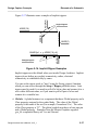
Nets and Buses and Net Bundles
Nets, buses, and net bundles are used to connect the different parts of a circuit. A
net is the fundamental unit of connection. A net is a single connection (called a
wire), a set of connections (called a bus), or a group of wires and buses (called a
bundle), that binds instances of symbols together at their pin locations through
multiple hierarchies of the design. Nets on the same sheet, and different sheets in
the same schematic, having the same name are automatically tied together. Proper
net connectivity is defined by a set of checks, described in Appendix A, "DA
Design Checks".
A bus has the same electrical meaning as a set of individual nets bound together.
Buses have a defined width, derived from the number of elements in the bus. The
expression A(0:15) defines a bus with a width of 16 nets. Each net is referenced
sequentially: A(0), A(1), ..., A(15) through the array. The expression B(0:2;5:7)
defines a two-dimensional bus of nets B(0;5), B(0;6), B(0;7), B(1;5), ..., B(2;7).
In Design Architect, a net name is defined by selecting the net vertex and adding
the net name as the Net property value. Net and bus names are discussed in more
detail beginning on page 2-24. A discussion about property name/value
restrictions begins on page 3-7.
2-22
Design Architect User’s Manual, V8.5_1
Design Capture Concepts
!
Caution
Elements of a Schematic
Board layout applications may not be able to recognize and utilize
multi-dimensional buses, such as A(0:7;0:7), since they consider a
multi-dimensional bus to be a single net joining all attached pins.
A net bundle is an ordered collection of nets, buses, and other net bundles. Each
item within a net bundle represents a separate signal, whereas the net bundle
represents a grouping of multiple signals which are often interrelated in some
way. Net bundles cannot span design hierarchy, since they are simply a means of
collecting a set of signals into a logical unit in a single schematic. Proper net
bundle connectivity is defined by a set of checks, described in Appendix A, "DA
Design Checks".
Global connections can be referenced by nets, rather than creating a net route to a
global symbol component such as Vcc. Global components have a Global
property and a Class property. The Global property value is the name of the net
(for example, Vcc), and the Class property value is "G", which defines it as
global. In order to establish connectivity to these global instances, you need to
assign the Global property to the desired net; the property value is the net name
(for example, Vcc). Global components available in gen_lib include Ground,
Vcc, Vcc.n, and Vee.
When a design has global nets, they are listed as "//net_name" when the design is
evaluated in the Design Viewpoint Editor (DVE). All other nets (not global) are
listed as "/net_name".
Bundle Syntax
Net and pin bundles are named using the following syntax:
explicit_name=base_name[left_delimiter[dimension;...]right_delimiter...,[] ...]
left_delimiter = '{'
right_delimiter = '}'
dimension = range...[,range]
Design Architect User’s Manual, V8.5_1
2-23
Elements of a Schematic
Design Capture Concepts
The enclosed left and right brackets denote an optional block. The "..." characters
denote an optional repeating block.
• explicit_name is the base_name of the bundle, plus a collection
description. The base_name can be any legal name allowed in Design
Architect. Delimiters (braces) are required. No space is allowed between
the base_name and the delimiters.
• base_name is a text string.
• dimension defines the collection of nets, buses, and nested bundles
delimited by braces. Multiple dimensions can be defined inside a set of
delimiters and separated by commas.
The following are examples of dimensions within bundle delimiters:
• {a,b,c,d} -- Defines a bundle of pins or nets labeled "a", "b", "c", and
"d".
• {w,x,y(0:1),bund{l,m,n}} -- Defines a bundle of pins or nets that
consists of single bits "w" and "x", an array of "0" and "1", and a bundle
of "l", "m", and "n".
Pin and Net Naming Syntax
In Design Architect, pins, nets and buses are named using the following syntax:
name = AMPLE_expression or explicit_name
explicit_name=base_name[left_delimiter[dimension;...]right_delimiter...,[] ...]
base_name = string with no delimiters, or slashes
left_delimiter = '[', '(', or '<'
right_delimiter = ']', ')', or '>'
dimension = range...[,range]
2-24
Design Architect User’s Manual, V8.5_1
Design Capture Concepts
Elements of a Schematic
range = field or field:field
field = AMPLE_expression or number
The enclosed left and right brackets denote an optional block. The "..." characters
denote an optional repeating block.
• AMPLE_expression must comply with AMPLE syntax and evaluate to a
valid explicit_name.
• explicit_name is the base_name of the pin or net (bus), plus an optional
array description. The base_name can be any legal name allowed in Design
Architect. No space is allowed between the base_name and the delimiters.
Delimiters (square brackets or parentheses) are required if an array is
specified.
• base_name is a text string with no delimiters or slash characters.
• dimension defines an array of nets delimited by either brackets,
parentheses, or angle brackets. Multiple dimensions can be defined inside a
set of delimiters and separated by a semicolon.
The following list describes some array descriptions for single and multiple
dimensional arrays:
• (2) -- Defines a single pin or net labeled "2".
• (0:15) -- Defines an array of pins or nets labeled "0", "1", and so on, up
to "15".
• (1,3,5,7) -- Defines an array of pins or nets labeled "1", "3", "5", and
"7".
• (0:2; 0:2) -- Defines a two-dimensional matrix with array elements
labeled "0,0", "1,0", "2,0", "0,1", "1,1", "2,1", "0,2", "1,2", and "2,2".
For information on ripping bits from a two-dimensional bus, refer to
"Special Instances" beginning on page 2-33.
Design Architect User’s Manual, V8.5_1
2-25
Elements of a Schematic
Design Capture Concepts
Table 2-1 lists a variety of net, bus, and bundle naming examples.
Table 2-1. Net, Bus, and Net Bundle Naming Examples
Net Name
Description
A
A single net name
A(0:15)
A bus whose range is 16 bits (0 through 15)
A(2) or A[2]
The number 2 net of the bus named "A"
a_bus(1,3,5,7)
A reference for the four bits "1,3,5,7" in a_bus
B(0:2;0:2)
A matrix of nets, sized 3 nets by 3 nets
B(1:n)
A parameterized net range "n" bits wide
Bundle{a,b,c}
A bundle containing nets "a", "b", and "c"
Cable{Clk, Data(0:3)}
A bundle containing a net "Clk" and a four-bit-wide
data bus.
($strcat("A(0:", n,")"))
The AMPLE function $strcat concatenates the
string "A(0:" with net range variable "n" and the
final right parenthesis ")" to build a net name from
an expression.
For detailed information on pin and bus name character restrictions, refer to
"Special Case Restrictions" beginning on page 3-8.
2-26
Design Architect User’s Manual, V8.5_1
Design Capture Concepts
Elements of a Schematic
Net Bundle and Pin Bundle Connection
You can connect a net bundle to either a pin bundle with the same width or a bus
pin of the same width. The connections of nets to pins are determined by position;
that is, the first item listed in the pin bundle is connected to the first item listed in
the net bundle, and so on.
You can connect a bus to a pin bundle of the same width. The connection
between bus bits and pins are determined by position; that is, the MSB (most
significant bit -- left----most index in the subscript) of the bus is connected to the
first element in the pin bundle, and so on.
An example of net bundle and pin bundle connections is illustrated in Figure 2-10.
(1)
(2)
(3)
U1_nets{x,y,z}
U1_pins{a,b,c}
U2_nets{2:0}
U2_pins{a,b,c}
U2_nets{x,c(0:1)}
U3_pins{0:2}
Figure 2-10. Net Bundle/Bus and Pin Bundle Connections
The connections made by mapping positions within the bundles and buses are:
1. Net "x" of U1_nets connects to pin "a" of U1_pins, net "y" of U1_nets
connects to pin "b" of U1_pins, and net "z" of U1_nets connects to pin "c"
of U1_pins.
2. Bit "2" of U2_nets connects to pin "a" of U2_pins, bit "1" of U2_nets
connects to pin "b" of U2_pins, and bit "0" of U2_nets connects to pin "c"
of U2_pins.
Design Architect User’s Manual, V8.5_1
2-27
Elements of a Schematic
Design Capture Concepts
3. Net "x" of U3_nets connects to U3_pins bit "0", net "c(0)" connects to
U3_pins bit "1", and net "c(1)" connects to U3_pins bit "2". This particular
example shows that wide signals in a net bundle are flattened to individual
signals before connections are made.
Unnamed Nets Connected to Pin Bundles
When an unnamed net connects either two pin bundles of equal width, or a pin
bundle and a wide pin of equal width, the system creates an unnamed bus. The
enumeration for the unnamed bus is in descending order, such as (1:0) and
connections are made by mapping positions in each pin object. Figure 2-11
illustrates the connectivity generated when using unnamed buses to connect pin
bundles.
U1{a,b,c}
N$10
U2{x,y,z}
Figure 2-11. Unnamed Net Connections to Pin Bundles
The system creates a bus named N$10(2:0), which has the following
connectivities:
• N$10(2:0) connects pin bundles U1{a,b,c} and U2{x,y,z}.
• N$10(2) connects pins "a" and "x".
• N$10(1) connects pins "b" and "y".
• N$10(0) connects pins "c" and "z".
2-28
Design Architect User’s Manual, V8.5_1
Design Capture Concepts
Elements of a Schematic
Nets Ripped by Name from a Net Bundle
You can separate, or rip, individual nets from a net bundle, just as you can rip bits
from a bus. Figure 2-12 illustrates acceptable ways in which you can rip nets and
buses from net bundles:
(1)
Bund{clk, Q, reset, bus(3:0)}
reset
reset
Bund{clk, Q, reset, bus(3:0)}
(2)
reset
(3)
board_reset
Bund{clk, Q, reset, bus(3:0)}
bus(1)
bus(1)
Bund{clk, Q, reset, bus(3:0)}
(4)
bus(2:1)
subbus(1:0)
Figure 2-12. Ripping from a Net Bundle
1. A bundle item can be ripped by name from a net bundle and connected to a
net with the same name as the bundle item; this is the typical case.
2. A bundle item can be ripped from the net bundle and connected to any other
net, which essentially shorts the two nets together. In this example, "reset"
and "board_reset" are electrically equivalent.
3. An individual bit of a bus that is a member of a net bundle can be ripped
from the bundle and attached to any net. If the attached net has a different
name than the bus bit, the bit and net are shorted.
Design Architect User’s Manual, V8.5_1
2-29
Elements of a Schematic
Design Capture Concepts
4. Any sub-range of a bus that is an item in a bundle can be ripped and
connected to another bus of matching width. Also, the entire bus can be
ripped from the bundle.
!
Caution
If you rip a bit from a bus and connect it to a net and then rip the
same bit from the bus and connect it to another net, the system
considers the two nets as shorted together.
For an operating procedure on ripping nets from net bundles, refer to "Ripping
Members from Net Bundles" on page 6-65.
Unnamed Nets Ripped from Net Bundles
When an unnamed net is connected to a ripper from a bundle, the net is one of two
types:
• A single-bit net. Ripper rule must list one item.
• An unnamed bus. Ripper rule must list multiple items.
If an unnamed bus results, it has a width that matches the ripper rule, is in
descending order, and is connected by position. Figure 2-13 illustrates the two
possible cases:
N$17
(1)
x,x,y
BUND{x,y}
x
(2)
N$18
Figure 2-13. Unnamed Nets Ripped from Net Bundles
2-30
Design Architect User’s Manual, V8.5_1
Design Capture Concepts
Elements of a Schematic
The following objects are defined:
1. A bus named N$17(2:0). Net N$17(2) connects to net "x", net N$17(1)
connects to net "x", and net N$17(0) connects to the net "y".
2. The unnamed net N$18 connects to net "x".
Design-Wide Net Naming Rules
A net representing a set of connected nets in a fully evaluated design is called a
design-wide net. If a design has more than one level of hierarchy, a design-wide
net spans the design hierarchy. Each segment of the design-wide net can have a
different net name. When the design is evaluated, the set of nets that make up the
design-wide net name evaluates to only one name.
The following rules determine which design-wide net is chosen as the
representative from a set of equivalent design-wide nets.
1. If one or more of the nets is Global, the global net defined in the highest
level in the design hierarchy is chosen. If there is more than one global net
at that level, a net is chosen according to the following ranking system:
a. If any of the nets are bus bits, choose the net with the widest bus parent.
b. If a representative net has not been determined (either no bus bits, or
parent buses have the same width), then choose by alphabetical order.
2. If no nets are Global, use the following criteria, in order, until all nets
except one have been eliminated:
a. Highest level in the hierarchy
b. EXTERNAL net (connected to a port) state
c. Net with a user-given name
d. Bus bit with widest bus parent
e. Alphabetical order
Design Architect User’s Manual, V8.5_1
2-31
Elements of a Schematic
Design Capture Concepts
Frames
A frame is a graphical box which encloses some circuitry that is repeated or
conditionally included in a final netlist by a frame expression. FOR, IF, and
CASE frame expression types are described starting on page 3-30. Frames are
used on schematic sheets only.
In order for the contents of a frame to be evaluated correctly, certain connectivity
rules must be followed. A full set of checks that define the proper frame
connectivity is described in Appendix A, "DA Design Checks".
Repeating Instances
A repeating instance is a short-hand way to specify a simple FOR Frame. A
repeating instance enables you to repeat a single instance by entering a
one-dimensional range in the “INST” property; for example, INST = XINST(3:0).
Using this optional range in the INST property value defines the number of times
the instance is repeated and how the nets are connected to each repeated instance.
Connections are implied by the ratio of the dimensions of a connected wire or bus
to the dimensions of the pin of the repeated instance.
The system creates a FOR frame to match the expression and connectivity of the
repeated instance when the sheet is written to the EDDM database. Because a
FOR frame is created for a repeating instance, downstream tools are not able to
tell the difference between a real FOR Frame and the short-hand FOR Frame of a
repeating instance.
Repeating instances should be used only in very simple cases. For more robust
purposes, you should use standard FOR frames. FOR frame expression types for
repeating instance are described on page 3-33.
2-32
Design Architect User’s Manual, V8.5_1
Design Capture Concepts
Elements of a Schematic
Instances
An instance is a reference to a component symbol, and reflects the connectivity
defined by that component symbol. An instance is graphically represented by a
symbol and can be updated by updating the original symbol. Placing the
representative symbol on a schematic sheet is called instantiation.
In order for an instance to be evaluated correctly, it must follow a set of
connectivity rules. A full set of checks that define the proper instance
connectivity is described in Appendix A, "DA Design Checks".
Special Instances
Special instance connectors are not part of the final evaluated design, and are not
translated into physical components. They are used to pass connectivity
information to the Design Viewpoint Editor (DVE), QuickSim II, and other
downstream applications that define or use an evaluated design. They are created
by adding specific Class property values to an instance. Refer to page 3-27 for
more information about Class properties.
You may define your own special instance symbols, or use Mentor Graphics
supplied components. The following list defines Mentor Graphics-supplied
special instances located in gen_lib (access gen_lib through the $MGC_GENLIB
environment variable):
• Net Connector. The net connector is used to connect two nets that have
different net names. The net name is assigned by adding the Net property
to a net vertex. It is not possible to attach more than one name to a net
because conflicting property values are not allowed. Two nets with
different net names can be connected by attaching the first net to the pin on
one side of the net connector, and the second net to the pin on the other side
of the net connector. If two nets with the same name are attached to a net
connector, or if a net attached to a net connector is unnamed, when the sheet
is checked, the Check command issues a warning.
A net connector has a Class property value "C" and at least two pins. The
netcon component is a Mentor Graphics-supplied net connector, and is
located in the gen_lib library. Refer to page 6-61 for information about
how to use the netcon component.
Design Architect User’s Manual, V8.5_1
2-33
Elements of a Schematic
Design Capture Concepts
• Off-Page Connector. The off-page connector is used to connect nets with
the same name across different sheets in a schematic. Nets with the same
name, which are not graphically connected in the schematic, are
automatically connected. To identify a net as connected by name across
sheet boundaries of the schematic, attach each such net to a pin of an offpage connector.
Table 2-2 summarizes the checking for off-page connectors during a Check
-Schematic.
Table 2-2. Checking for Offpage Connectors
Connectors/Matching Names
Check -Schematic Results
No connectors in design
No checking for offpage connectors.
1 connector / matching net name
Warning: Add connector to net with
same name.
1 connector / no matching net
name
Warning: Unneeded connector; no
matching net name found on other
sheets.
connectors on mismatched names / Warning: Add connectors to matching
matching names have no
names.
connectors
Connectors on nets of different
names
All three of the above warnings are
possible.
An off-page connector has a Class property value "O", and at least one pin.
The offpag.out and offpag.in components are Mentor Graphics-supplied
off-page connectors, and are located in the gen_lib library.
• Port. The port component is used to indicate a net making a connection
external to the schematic. The number and net names of the ports on a
schematic should match the pins on the interface of the symbol representing
that schematic. Refer to page 2-75 for a definition of a component
interface, and page 2-78 for a discussion about symbol registration. If the
net name attached to a port in the schematic does not match the name of a
2-34
Design Architect User’s Manual, V8.5_1
Design Capture Concepts
Elements of a Schematic
pin on its representative symbol when the schematic is checked, the Check
command issues an error.
A port has a Class property value "P", and must have exactly one pin. The
portin and portout components are Mentor Graphics-supplied port
components, located in the gen_lib library.
• Bus Ripper. A bus ripper is similar to a net connector. It connects two
nets of possibly different names, and provides a way to rip off a single-bit
or sub-bus of a bus for connection to a different net. For example, it
permits connecting net N(1) to B(1) of bus B(0:7).
The bus must be attached to the ripper pin named "Bundle". The ripped
nets must be attached to the corresponding ripper pins. In addition, the
value of the Rule property attached to the ripper must have a valid bus
range syntax to identify the bits to be ripped from the main bus; for
example, a value bit "1" of range "0:3". The net must be named so that its
width matches the width specified by the Rule property.
When ripping bits from a two-dimensional bus, the value of the Rule
property must be set to rip one bit from the bus or to rip a range of bits from
a row or column of the bus. The following list shows the syntax and a
sample Rule property value for each possible type of rip. The sample
values assume that the bus is named "data(0:2;0:2)" and that the width of
the nets attached to the rip component match the width specified in the Rule
property:
x;y Rip one value from the matrix. For example:
Rule = 0;0
x;y :y Rip a range of values from a row in the matrix. For example:
1
2
Rule = 1;0:2
x :x ;y Rip a range of values from a column in the matrix. For example:
1
2
Rule = 0:2;1
Design Architect User’s Manual, V8.5_1
2-35
Elements of a Schematic
Design Capture Concepts
A bus ripper instance has a Class property value "R". It must have at least
two pins. One pin must have a Pin property with value "Bundle". A Rule
property must be associated with the instance body or with each nonbundled pin. The value of the Rule property must have a valid bus range
syntax.
The rip component is a Mentor Graphics-supplied component, located in
the gen_lib library. The rip component provides a wide variety of ripper
symbols capable of ripping varying numbers of bits from a bus. Refer to
page 6-49 for an example of how to create a bus ripper.
• Implicit Ripper. An implicit ripper separates a named bit from a bus or a
member from a net bundle. It differs from a standard ripper symbol in that:
o The implicit ripper is not an actual symbol in any library.
o Implicit rippers do not have a Rule property attached to them, since
connection is established by name.
You can visually differentiate an implicit ripper from a standard ripper in
that the implicit ripper instance is the same color as a net. The name of the
net connected to the implicit ripper must exactly match the name of a bus
bit or member of a net bundle. You can configure implicit rippers to
connect at a 45-degree angle, much like standard rippers, or in a straight
line.
2-36
Design Architect User’s Manual, V8.5_1
Design Capture Concepts
Elements of a Schematic
ADDR(4)
Figure 2-37 illustrates some examples of implicit rippers.
Angled rippers
ADDR(0)
ADDR(7:0)
ADDR(7)
Straight rippers
ADDR(3)
x
BUND1{s1, x, y, ADDR(7:0), s2}
Figure 2-14. Implicit Ripper Examples
Implicit rippers are the default when you invoke Design Architect. Implicit
rippers do not define any explicit connectivity; rather, electrical
connectivity is established only by name.
You can set the ripper mode to "auto" using the $setup_ripper() function,
which you can access through the Setup > Ripper pulldown menu. Auto
rippers must be used if you need to pull off a bit in a bus and connect it to a
wire with a different name, or if you want to pull off part of a bus and
connect it to a smaller bus.
• Globals. A global instance is a component that has a Global property and a
Class property assigned to the symbol body. The value of the Global
property is the name of the net (for example, Ground and Vcc). The value
of the Class property is "G". The global symbol must have at least one pin
and a Global property. Examples from the Mentor Graphics-supplied
gen_lib component library are Vcc and Ground.
Design Architect User’s Manual, V8.5_1
2-37
Elements of a Schematic
Design Capture Concepts
A global instance can exist at any level of the design. Nets that connect to
the global instance, without creating a physical net route, must have a Net
property value that is the same as the Global property value on the global
instance to establish electrical connectivity.
• Null Instance. A null instance is a component that carries the component's
properties, but represents the component as electrically inert. In many
cases the null function of a component can be provided using comments
instead. A null instance has a Class property value "N" and no pins.
Comment Objects
Comment objects are graphical objects, such as lines, circles, rectangles, and text,
combined together for descriptive purposes. Comment objects can be used as
explanations, review notes, fabrication notes, or any purpose you have to
comment the design. Comment objects have no electrical significance.
Types of Comment Objects
The following are comment objects:
• Arcs
• Circles
• Lines
• Polygons
• Dots
• Polylines
• Rectangles
• Text
2-38
Design Architect User’s Manual, V8.5_1
Design Capture Concepts
Elements of a Schematic
Graphic Commands
Graphic commands create comment text and graphics on schematic sheets and
symbol graphics on symbols. The term symbol graphics refers to the lines,
rectangles, circles, and other graphical objects used to create symbol bodies. The
same graphics-generating command set is used in both schematic editing and
symbol editing.
The following commands generate comment text and graphics:
• Add Arc
• Add Circle
• Add Dot
• Add Line
• Add Polygon
• Add Polyline
• Add Rectangle
• Add Text
• Convert to Comment
Most comment-generating commands are self-explanatory; for example, the Add
Rectangle and Add Circle commands add rectangles and circles to a schematic
sheet. The Add Dot command adds a dot to a symbol body; the size and style of
the dot drawn on the symbol instance are determined by the values of the dot_size
and dot_style internal state variables (same size and style as the DA- generated net
junction dots). Other comment object attributes control how lines, text, and other
graphics are displayed, and are described starting on page 2-44. Refer to the
Design Architect Reference Manual for more detailed information about these
commands.
Design Architect User’s Manual, V8.5_1
2-39
Elements of a Schematic
Design Capture Concepts
Convert Objects to Comments
The Convert To Comment command converts any selected electrical or graphical
object, or group of objects, to comments. For example, selected:
• Nets become comment lines
• Symbol instances become comment text and graphics
• Visible properties become properties of the newly created comment object
!
Caution
After an object has been converted to a comment, all hidden
properties associated with that object are deleted. This process can
be reversed using the Undo command.
Uses for Comments
Using comment text, graphic objects, and system functions that return standard
information (such as date and version numbers of the design), you can create
many useful structures that are distinct from the electrical elements of the
schematic. For example, you can create:
• Title blocks (can be automatically created on a new sheet)
• Revision blocks
• Page borders (can be automatically created on a new sheet)
• Backplane, wire wrap, and other tentative design elements
• Explanations, review notes, and fabrication notes
2-40
Design Architect User’s Manual, V8.5_1
Design Capture Concepts
Elements of a Schematic
Object Handles in Design Architect
In Design Architect, every graphical comment and electrical object has an
associated handle. A handle is a unique, system-assigned identifier. You can also
assign a name to an instance with the Inst property. The system recognizes the
name you assign, but the instance handle is retained, not replaced. A handle
consists of one of the key letters listed below, followed by the dollar sign
character ($) and a system-assigned number.
• B = Bundle
• C = Comment
• F = Frame
• G = Group
• I = Instance
• N = Net
• P = Pin
• T = Property Text
• V = Vertex
An example of an instance handle is:
I$385
Handles, like this one, appear in various error messages and netlists. The handle
can be specified as an argument in commands such as Select By Handle or Report
Object, as in the following examples:
Select By Handle I$385 -View
Report Object I$385
The first command selects the object by its handle. The second command requests
an extended status list associated with the object whose handle is I$385.
Design Architect User’s Manual, V8.5_1
2-41
Elements of a Schematic
Design Capture Concepts
Methods exist to make the handle of an instance visible. Assign the Inst property
to the instance with a value of I$0. When the Check or Save commands are
issued, the I$0 value will be replaced by the unique handle for that instance.
Similarly, assigning the Net property a value of N$0 makes the net handles visible
after the Check or Save commands are executed.
Object Attributes
Text, lines, arcs, rectangles, nets, property values and many other objects
associated with a schematic or a symbol have additional graphical attributes. A
graphical attribute is a feature that affects the way the object is displayed.
Line Style Attributes
You can use different line styles and widths for lines created for symbol graphics
or comment graphics, for example:
• Line style: solid, dotted, long dashed, short dashed
• Line width: 1 pixel, 3 pixels, 5 pixels, 7 pixels
A line and a net may have the same line style attributes, but only a net can have
electrical connectivity. A net is created with the Add Wire or Add Bus command,
and a line is created with the Add Line command.
2-42
Design Architect User’s Manual, V8.5_1
Design Capture Concepts
Elements of a Schematic
Text Attributes
Serif font
Monospaced font
Sans Serif font
Text Orientation (90 deg.)
Design Architect supports a variety of text attributes for text objects. Figure 2-15
shows some of these styles. Comment text and property text attributes include:
font type, text height, text horizontal justification, text vertical justification, text
orientation, text visibility, and text transparency. Refer to the Setup Comment and
Setup Property Text commands in the Design Architect Reference Manual for
more information about these commands.
Text Orientation (0 deg.)
Figure 2-15. Text Attributes
Setting Up Attributes
There are three ways to set object attribute information:
• Execute the proper "setup" command
• Execute the proper "change" command
• Execute the individual "$set" function for each internal state variable
The Design Architect "Setup" commands are used to set all the object attributes
for subsequently created objects of a particular type. For example, the Setup
Comment command sets all the attributes for comment text and graphics. The
Setup Net command sets all the attributes for nets, such as style, width, pin snap,
and orthogonal routing. The Setup Property Text command sets all the attributes
for property text display. The attributes set with the "Setup" commands remain
Design Architect User’s Manual, V8.5_1
2-43
Elements of a Schematic
Design Capture Concepts
unchanged for all subsequently created objects. A summary of attribute
descriptions associated with each "Setup" command is displayed in Table 2-4.
The "Change" commands modify individual attributes of selected objects. For
example, the Change Property Visibility command toggles the instance-specific
selected property to a visible or invisible condition. The change commands do not
affect the default internal state variables. Object attributes associated with each
"Change" command are displayed in Table 2-4.
The "$set" functions work like the "Setup" commands except they set only one
internal state variable at a time; refer to Table 2-4. Refer to the Design Architect
Reference Manual for information concerning internal state functions.
Summary of Object Attributes and Associated Commands
Design Architect supports a variety of graphical attributes that can be used to
customize the look of your schematic. Table 2-3 catalogs the attributes available
for each object.
Object Types
Table 2-3. Object Attributes
Object Attributes
Comment Text line style, line width, fill type, text font, text height,
and Graphics
horizontal text justification, vertical text justification, text
orientation, transparency
Net
net style, net width, orthogonal, orthogonal angle
Property
name, value, type, visibility, text font, text height, text
justification, text orientation
Symbol
Graphics and
Comments
line style, line width, fill pattern, text font, text height,
horizontal text justification, vertical text justification, text
orientation
Table 2-4 lists the object attributes with the associated commands and functions
used to set and change these attributes. This table points you to the commands
2-44
Design Architect User’s Manual, V8.5_1
Design Capture Concepts
Elements of a Schematic
and functions necessary to set or change an individual object attribute, or to set or
change the sheet/symbol default for a particular attribute.
Table 2-4. Command and Function
Attribute Reference
Attribute Descriptions
Design Architect
Commands/Functions
Line Style (solid, dot, shortdashed,
longdashed)
Setup Comment
Setup Symbol Body
Change Line Style
$set_line_style()
Line Width (1pixel, 3pixels, 5pixels, 7pixels) Setup Comment
Setup Symbol Body
Change Line Width
$set_line_width()
Polygon Fill (clear, solid, stipple)
Setup Comment
Setup Symbol Body
Change Polygon Fill
$set_polygon_fill()
Net Style (solid, dot, shortdashed,
longdashed)
Setup Net
Change Net Style
$set_net_style()
Net Width (1pixel, 3pixels, 5pixels, 7pixels)
Setup Net
Change Net Width
$set_net_width()
Orthogonal Routing of net (on, off)
Setup Net
$set_orthogonal()
Orthogonal Routing Angle (angle)
Setup Net
$set_orthogonal_angle()
Dot Size (dotsize)
Setup Symbol Body
Setup Net
$set_dot_size()
Design Architect User’s Manual, V8.5_1
2-45
Elements of a Schematic
Design Capture Concepts
Table 2-4. Command and Function
Attribute Reference [continued]
Attribute Descriptions
Design Architect
Commands/Functions
Dot Style (square, circle)
Setup Symbol Body
Setup Net
$set_dot_style()
Ripper Dot Toggle (on, off)
Setup Net
$set_ripper_dot()
Pin Snap to grid (on, off)
Setup Net
$set_pin_snap()
Text Font for property and comment text
Setup Comment
Setup Property Text
Change Text Font
Change Property Font
$set_text_font()
$set_property_font()
Text Height for property and comment text
Setup Comment
Setup Property Text
Change Text Height
Change Property Height
$set_text_height()
$set_property_height()
Text Horizontal Justification (left, center,
right) for property and comment text
Setup Comment
Setup Property Text
Change Text Justification
Change Property Justification
$set_text_hjustification()
$set_property_hjustification()
2-46
Design Architect User’s Manual, V8.5_1
Design Capture Concepts
Elements of a Schematic
Table 2-4. Command and Function
Attribute Reference [continued]
Attribute Descriptions
Design Architect
Commands/Functions
Text Vertical Justification (top, center,
bottom) for property and comment text
Setup Comment
Setup Property Text
Change Text Justification
Change Property Justification
$set_text_vjustification()
$set_property_vjustification()
Text Orientation (0,90) degrees
Setup Comment
Setup Property Text
Change Property Orientation
$set_text_orientation()
$set_property_orientation()
Visibility (on, off) for instance-specific
property display
Setup Property Text
Change Property Visibility
$set_property_visibility()
Build a Schematic
A schematic may include many instances, wires and buses connecting the
instances, comments to annotate the circuit, and special instances for special
connections. Refer to "Creating a Schematic" in the Getting Started with Design
Architect Training Workbook for a step-by-step tutorial on how to create a
schematic.
To build a simple schematic involves the following steps:
1. Open a Schematic Editor window
2. Draw a schematic
3. Check schematic for errors
4. Register schematic with component
Design Architect User’s Manual, V8.5_1
2-47
Elements of a Schematic
Design Capture Concepts
Open a Schematic Editor Window
The Open Sheet command opens a Schematic Editor window. You can activate
this command from the Session menu or the palette menu in Design Architect.
This command opens an existing schematic sheet if the schematic name exists, or
creates a new schematic sheet, if a new name is given. When you open a new
schematic sheet that does not have an existing symbol, you are also creating a new
component which, in the future, will contain other relevant objects such as a
symbol to represent the sheet, technology files, design viewpoints, and back
annotation objects.
You can also invoke a Schematic Editor window from the Design Manager by
double-clicking on a schematic sheet icon or its component icon. Refer to page
6-23 for the procedure to invoke the Schematic Editor from a Design Architect
Session window.
Draw the Schematic
Here are five basic steps that allow you to draw a simple circuit:
• Choose and place component symbols
• Draw and route nets
• Terminate off-sheet nets
• Name nets
• Add comments
Choose and Place Component Symbols
Component symbols are selected and placed on a schematic sheet from a library
palette or by typing the pathname to the component symbol. A library palette can
be activated by selecting a library menu item under the Libraries menu in the
Schematic Editor. A menu selection is available for every Mentor Graphics
component library installed. When activated, the library palette includes a list of
all library components available from that library. See "Choosing and Placing
2-48
Design Architect User’s Manual, V8.5_1
Design Capture Concepts
Elements of a Schematic
Component Symbols on a Sheet" on page 6-29 for procedures describing how to
select and place components on your schematic sheet.
Draw and Route Nets
After the component symbols have been placed, you can draw and route the nets
necessary to properly connect the component symbols. You can set the net router
to route automatically when a net is drawn, or you can manually route a set of nets
by selecting the net vertices to route and executing the Route command. To
activate automatic net routing, execute the Setup > Set Autoroute On menu
item. When automatic routing is turned on, the Route command is automatically
called after each net is drawn.
The net router defines an orthogonalized pathway for a connected net that avoids
instance extents, comment objects, and other nets. The net router utilizes the pin
snap grid as the routing grid. If net vertices are not on the grid, they are not
routed. Routing performance is faster if the pin snap grid is set to a value larger
than one pin interval during the route operation, and then set back for component
instantiation.
Unconnected wires, buses, and pins will cause warning messages when you check
the schematic sheet. If you want to indicate that an unconnected wire, bus or pin
is valid, attach the Class property to it with a value of "dangle". You may first
need to declare pins and nets as valid owners of the Class property.
To specify a property owner, choose the Setup > Property Owner/Type >
Property Owner menu item. In the dialog box that appears, enter "class" in the
Property Name text entry field, and click the Pins and Nets buttons.
See "Drawing and Routing Nets" on page 6-37 for procedures to draw and route
nets.
Design Architect User’s Manual, V8.5_1
2-49
Elements of a Schematic
Design Capture Concepts
Terminate Off-Sheet Nets
All input wires and buses should begin with a portin or offpag.in component from
the gen_lib component library. Similarly, output nets and buses should be
terminated with a portout or offpag.out component. Warnings may result if this is
not done.
See "Choosing and Placing Component Symbols on a Sheet" on page 6-29 for
procedures for placing these components on your schematic sheet.
See "Assigning Properties and Property Owners" on page 6-95 for details about
how to add property values.
Modify Net Names
A net should always terminate at an instance's pin, or connect with another net at a
junction. The Schematic Editor uses several components for terminating a net at
an input or output point. The components portin, portout, offpag.in, and
offpag.out provide net termination. By default, the portin and portout symbols
assign the name NET to an unnamed net when attached. To prevent many
different nets from being named NET (if two nets have the same name,
downstream applications see them as being connected), you will need to change
the name of the nets so they each have a unique name.
See "Modifying Net Names" on page 6-39 for a procedure for modifying a net
name.
Add Comments to the Schematic Sheet
Comment objects are graphical objects, such as lines, circles, rectangles, and text,
combined together for descriptive purposes. Comment objects can be used as
explanations, review notes, fabrication notes or any purpose you have to comment
the design.
To review commands used to add comment objects, refer to "Types of Comment
Objects" on page 2-38.
2-50
Design Architect User’s Manual, V8.5_1
Design Capture Concepts
Elements of a Schematic
Check the Schematic
You must pass a set of required Mentor Graphics schematic checks before a
downstream application is invoked; if these checks fail, the downstream
application will issue a warning, highlighting a problem that may be uncovered at
a later time. These checks are set up for you by default, and are executed with the
Check > With Defaults menu item.
To understand the additional capabilities of the Check command, refer to "Design
Error Checking" starting on page 5-1. To find out how you can change your setup
to include optional checks to be executed by default, refer to page 6-41.
Register Schematic with Component
You must register your schematic with a component before you can use the
schematic with a downstream tool. When you save your schematic, for example,
by executing the File > Save Sheet menu item, by default, you register your
schematic with the component specified when you opened the schematic sheet. If
you want to register your schematic with other components and component
interfaces, you need to know more about how the component structure works.
Refer to "DA Model Registration" on page 2-73 for concepts related to the
component structure and model registrations; for a procedure describing how to
register a schematic, refer to "Saving a Sheet and Registering a Schematic" on
page 6-44.
Design Architect User’s Manual, V8.5_1
2-51
Elements of a Symbol
Design Capture Concepts
Elements of a Symbol
The following topics define the concepts and terminology related to the objects
used to build a symbol.
Symbol Definition
The Symbol Editor creates symbol models. A symbol model is a graphical
representation of a component, as shown in Figure 2-16. A symbol consists of
five basic elements:
• Body (Shape). The symbol body is the graphical image of the symbol.
The graphics that display the symbol body are called symbol graphics.
• Pin(s). Pins are points where an instance of the symbol electrically
connects to the schematic sheet.
• Origin. The origin is the reference point used to place the symbol on the
schematic sheet.
• Properties. Properties provide information describing the functionality of
the symbol. Refer to page 3-1 for more information about properties.
• Comments. Comments placed on a symbol provide documentation about
the symbol. Comments cannot be added directly to a symbol; symbol
graphics can be converted to comment graphics with the Convert To
Comment command, and back to symbol graphics with the Remove
2-52
Design Architect User’s Manual, V8.5_1
Design Capture Concepts
Elements of a Symbol
Comment Status command. Comments on a symbol are non-instantiable
and do not appear on an instance of the symbol.
SHAPE
(BODY)
PIN
ORIGIN
POINT
PROPERTIES
(TEXT)
COMMENT TEXT
PRE
D
Q
CLK
QB
CLR
Modified 12/13/92
Figure 2-16. Symbol Structure
Symbol and Schematic Relationships
Instances of symbol models and schematics form a hierarchical bond. An
instance, as illustrated on the right portion of Figure 2-17, represents a higherlevel function to the sheet it references. The schematic below the instance of the
flip-flop represents a more detailed level description of the function of the symbol
model.
The flip-flop schematic sheet is said to be lower in the design hierarchy than the
circuit schematic sheet. This is true because the flip-flop schematic is the
functional representation for the flip-flop symbol model, which is one of the
components using lower-level schematics. Sheets at the lowest level contain
components that are usually simple gates.
For down-stream applications such as simulation, the functionality of some lowlevel components is already known by the simulator and does not require another
underlying schematic sheet. Such a component is referred to as a built-in
primitive.
Design Architect User’s Manual, V8.5_1
2-53
Elements of a Symbol
Primitive
Component
Symbol
Design Capture Concepts
This hierarchical bond between the symbol model and the schematic also allows
the flexibility to represent that symbol with other functional models. Other more
complex modeling methods can also be used to describe component functioning
for primitives. Refer to the Digital Modeling Guide for more information about
different modeling techniques.
Schematic
Sheet
Flip-Flop
Instance
D
Q
CLK
CLR
PRE
Flip-Flop
Symbol
QB
Flip-Flop
Schematic Sheet
Figure 2-17. Symbol and Schematic Relationships
2-54
Design Architect User’s Manual, V8.5_1
Design Capture Concepts
Elements of a Symbol
Build a Symbol
The following topics present some of the common procedures involved in
building a symbol. Refer to "Creating a Symbol" in the Getting Started with
Design Architect Manual Training Workbook for a step-by-step tutorial on how to
create a symbol.
Creating a symbol involves the following steps:
1. Open a Symbol Editor window
2. Draw the symbol body
3. Add pins and pin properties
4. Add other symbol properties
5. Check a symbol for errors
6. Register the symbol with the component
Open a Symbol Editor Window
The Open Symbol command opens a Symbol Editor window. You can activate
this command from the Session menu or the palette menu in Design Architect.
This command opens an existing symbol, if the symbol name exists, or creates a
new symbol, if a new symbol name is given.
You can also invoke the Symbol Editor from the Design Manager by doubleclicking on a symbol icon. Refer to page 6-72 of this manual for more
information about how to invoke the Symbol Editor on an existing symbol.
Draw the Symbol Body
A symbol body can be made up of lines, rectangles, circles, and arcs. A symbol
body can also have "whiskers" which are short lines projecting from its body to
indicate where the input and output pins will be connected. Whiskers are not a
required part of the symbol, but rather a convention used in the Mentor Graphics
component libraries.
Design Architect User’s Manual, V8.5_1
2-55
Elements of a Symbol
Design Capture Concepts
The following list presents commands used to draw the symbol body:
• Add Arc
• Add Circle
• Add Dot
• Add Line
• Add Polygon
• Add Polyline
• Add Rectangle
• Add Text
Add Pins and Pin Properties
You add pins to a symbol with the Add Pin command. The pin name that you
give as the Pin property is stored in the database as the compiled pin name. A
compiled pin name is a non-volatile pin name on library symbols against which
Hardware Model Language files and Behavioral Language Model files can be
compiled.
When you make changes to the Pin property value (by changing the pin's userdefined name), with the Change Property Value command, the compiled pin name
tracks the user pin name. If you change the compiled pin name with the Change
Compiled Pin Name command, future changes to the user pin name will not affect
the compiled pin name. If you wish to have the compiled pin name again track the
user pin name, set the compiled pin name value to " " with the Change Compiled
Pin Name command. The compiled pin name is not a property and cannot be
viewed on the sheet. You can examine its value by executing the Report Object
command. Compiled pin names are not used for connectivity of an instance on a
schematic sheet.
2-56
Design Architect User’s Manual, V8.5_1
Design Capture Concepts
Elements of a Symbol
Add Other Symbol Properties
In addition to adding pins and their associated names, you will also want to add
and modify property values on pins, or on the symbol body itself.
Symbol properties attach data or characteristics about the symbol, and are
subsequently used during design simulation and by layout and other downstream
applications. The addition of properties allows accurate modeling of the real
physical device. Symbol model properties are necessary for the component to
operate correctly. A more detailed discussion of symbol properties starts on
page 3-9.
Add Comments to a Symbol
When you add graphics to a symbol, for example, with the Add Rectangle
command, by default, you create symbol graphics. Symbol graphics are included
with the symbol and are displayed with the symbol at instantiation time.
Comments are created by converting symbol graphics to comments with the
Convert to Comment command. Comments created on a symbol sheet are not
displayed on the sheet when the symbol is instantiated. They can only be viewed
on the symbol while editing the symbol.
If you want to convert selected symbol comments back to symbol graphics you
can execute the Remove Comment Status command.
To review commands used to add comment objects, refer to "Types of Comment
Objects" on page 2-38.
Check a Symbol
You must pass a set of required Mentor Graphics symbol checks or the symbol
will not be valid for instantiation. These checks are setup for you by default, and
are executed with the Check > With Defaults menu item.
To understand the additional capabilities of the Check command refer to "Design
Error Checking" starting on page 5-1. To learn how to include optional checks to
be executed by default, refer to page 6-90.
Design Architect User’s Manual, V8.5_1
2-57
Elements of a Symbol
Design Capture Concepts
Register Symbol with Component
You must register your symbol with a component before you can instantiate the
symbol. When you save your symbol, for example, by executing the
File > Save Symbol > Default Registration menu item, by default, you register
your symbol with a component, and use the component's leaf name for the symbol
name.
To understand more about symbol registration, refer to page 2-73. A procedure
describing how to register a symbol with a component interface is on page 6-92.
Create a Symbol from a Schematic
Design Architect can create a symbol to represent a schematic sheet. When you
choose the Miscellaneous > Generate Symbol menu item while in the Schematic
Editor, a dialog box is displayed for you to specify the name of the symbol that
will be created.
The symbol can be generated from the currently open schematic sheet, another
sheet, or a pin list. Options include replacing an existing symbol, opening the
newly created symbol for editing, and saving the new symbol.
2-58
Design Architect User’s Manual, V8.5_1
Design Capture Concepts
Elements of a Symbol
Create a Symbol from a Pin List
While in the Schematic Editor, you can generate a symbol from a pin list. Choose
the Miscellaneous > Generate Symbol menu item to display the Generate
Symbol dialog box (This dialog box is also available in the session window with
the File > Generate > Symbol menu item). When you click the Pinlist File
button, a text entry field appears for you to enter the file pathname, as shown in
Figure 2-18.
Generate Symbol
Component Name $PROJ_A/addr
Symbol Name
addr
Replace existing?
Once generated ...
Active symbol?
Yes
Save Symbol
Yes
No
Edit Symbol
No
Save and Edit
Choose Source
Pinlist File
Pinlist File
(Symbol must be saved)
Schematic
$PROJ_A/addr/pin_list.ascii
Current Shape:
Pin Spacing (in pin grids)
2
Shape Arguments:
Navigator...
box
[2,2]
Choose Shape
OK
Reset
Cancel
Figure 2-18. Generate Symbol Dialog Box
Design Architect User’s Manual, V8.5_1
2-59
Elements of a Symbol
Design Capture Concepts
The following code block shows an example of a pin list file.
// Mentor Graphics pin list file for symbol generation.
// Created: 05/16/94 by Fred Jones
pins {
"DIN(7:0)",
// Pin information
input, width 8, side 3, position_on_side 1,
no_bubble, no_edgesense;
"DIN(7:0)", input, width 8, side 3, position_on_side 1,
no_bubble, no_edgesense;
"DOUT(7:0)", output, width 8, side 1, position_on_side 0,
no_bubble, no_edgesense;
"CLK",
label "C", input, width 1, side 3,
position_on_side 0, no_bubble, edgesense;
}
body_props {
// Property information
name "W", text "W=", number, value "8", region 1;
name "INST", string, value "I$0", region 3;
}
shape buf, 4;
// Shape information
For detailed information about the constructs used in the pin list file, refer to the
"Pin List File Format" appendix in the Design Architect Reference Manual.
Edit Symbol In-Place
You can edit a symbol in-place on a schematic sheet. Errors such as mismatching
the symbol pins with connecting nets, or using incorrect pin spacing, are avoided
because you can modify the symbol model in the position of its instance on the
schematic.
You open a selected instance in-place on a schematic sheet with the Begin Edit
Symbol command. When the symbol is opened, the nets and instances on the
sheet are grayed out, but are still visible while you are editing the symbol
contents. All symbol editing commands are now accessible.
2-60
Design Architect User’s Manual, V8.5_1
Design Capture Concepts
Elements of a Symbol
It is possible to have another window open on the symbol. This allows both a
schematic context edit view, and a symbol window where the symbol can be
viewed and edited by itself (out of context of the schematic). Edits made in the
out-of-context window are visible on the symbol edited in-place.
You exit the symbol edit in-place mode and update the symbol instance on the
schematic sheet with the End Edit Symbol command. If you do not specify the Force switch and edits have been made but not written, you are prompted with a
"Save changes?" request. Answering with a "yes" response writes edits to disk
before closing the symbol. You can use the -Force command line switch to quit
out of edit, with no changes saved.
Make a Symbol on a Schematic Sheet
Instead of having to open a Symbol Editor window to execute the graphic
generating commands to create the symbol, you can make a symbol from
comment objects and symbol pins on your schematic sheet. This methodology is
useful for top-down design creation.
The Make Symbol command converts selected schematic comment objects and
symbol pins to symbol graphics, and then checks the symbol. If errors in any
required symbol checks are found, the command is aborted, and the selected
objects remain on the schematic sheet. If no errors are found, the selected
comment objects and symbol pins are deleted from the schematic sheet, and the
symbol model just created is instantiated in-place on the schematic sheet. If you
select objects other than comments and symbol pins, an error is reported.
NOTE: Symbol pins become part of a symbol when you issue the Make Symbol
command. If the pins on a schematic sheet have not been made part of a symbol
definition, an error will be reported with the required schematic sheet checks.
Design Architect User’s Manual, V8.5_1
2-61
Elements of VHDL
Design Capture Concepts
Elements of VHDL
The VHDL language has many constructs that are similar to objects used to create
schematics and symbols. Both methods are capable of fully describing the
structural and behavioral characteristics of a circuit. To learn about creating
VHDL models, refer to the appropriate topics from the following list:
• VHDL language constructs
IEEE Standard VHDL Language Reference Manual
Mentor Graphics Introduction to VHDL
Mentor Graphics VHDL Reference Manual
• VHDL text editing
QuickVHDL User's and Reference Manual
System-1076 Design and Model Development Manual
Notepad User's and Reference Manual
• Compiling VHDL models
QuickVHDL User's and Reference Manual
System-1076 Design and Model Development Manual
• VHDL model registration
"VHDL Registration" on page 2-83 (this manual)
2-62
Design Architect User’s Manual, V8.5_1
Design Capture Concepts
Object Selection
Object Selection
To work with objects on the screen, you must first select them. You can move,
copy, flip, rotate, or pivot a selected object (or group of objects), as well as
perform a variety of other operations. For selection procedures, refer to
"Selecting and Unselecting Objects" starting on page 6-6.
Topics related to object selection are as follows:
• General selection
• Specific selection
• Selection sets
• Reopen selection
• Reselection
• Selection filters
• Individual selection
• Text selection
• Selecting objects in multiple windows
• Unselecting objects
Design Architect User’s Manual, V8.5_1
2-63
Object Selection
Design Capture Concepts
General Selection
There are four common ways to select object(s):
1. Move the cursor over the object and click the Select (left) mouse button.
This action toggles the object between its selected and unselected state.
2. Put the cursor near the object(s) to select, hold the Select mouse button
down, drag an expandable box, called the dynamic rectangle, until all the
object(s) you want selected are in the rectangle, then release the Select
mouse button.
3. Put the cursor near the object(s) you want selected, hold the F1 (Select Area
Anything) function key down and drag the dynamic rectangle until all the
object(s) you want selected are in the rectangle. Release the function key.
4. Execute the appropriate Select menu items. For examples of using the
Select menu items, refer to "Selecting Objects" beginning on page 6-6.
Selection types 1 and 2 use the selection filter to define which type(s) of objects
are selected. To set up the selection filter, click on the Set Select Filter palette
button, or execute the Setup Select Filter command. Selection types 3 and 4 do
not use a selection filter; they select all object types within the dynamic rectangle.
Selection filters are described on page 2-68.
Specific Selection
You can specify what types of objects you want to select or unselect. Popup menu
items Select > All, Select > Area, and Select > Exterior let you choose one of
the following items:
• Comment graphics
• Comment text
• Frame
• Net
2-64
Design Architect User’s Manual, V8.5_1
Design Capture Concepts
Object Selection
• Pin
• Property
• Segment
• Symbol pin
• Symbol body
• Vertex
Other Select popup menu items let you select:
• Attached (nets, pins, instances, branches)
• By object handle
• By property (owners, name, type, value)
Selection Sets
Selected objects are called a selection set. Items are added to the selection set by
placing an object (instance, net) on the sheet or by selecting an existing object.
Multiple Select commands can add more items to the open selection set. If an edit
or report operation is performed, the selection set is closed, but the objects remain
selected. A closed selection set means that no more selections can be added to the
set. The next Select command or placement of a new object on the sheet creates
and opens a new selection set, and unselects all objects within the closed selection
set.
The Select Count in the status line shows whether the selection set is open or
closed. If the number of selected items is followed by a plus (+) character, the
selection set is open ("Sel. 2+"); otherwise, the selection set is closed ("Sel. 2 ").
Design Architect User’s Manual, V8.5_1
2-65
Object Selection
Design Capture Concepts
Reopen Selection
You can reopen the previously closed selection set with the Reopen Selection
command. This selection set remains open until another edit operation is
performed. For example, if you select three instances and rotate them (closing the
selection set), and then you want to move those three instances, plus four other
instances, you execute the Reopen Selection command, then select the additional
four instances, prior to performing the move.
Reselection
The previously closed selection set is called the reselection set. You can use the
Reselect command to select the reselection set. If the current selection set is open,
the Reselect command adds the contents of the reselection set to the current
selection set, leaving the selection set open. If the current selection set is closed, it
will become the new reselection set, and the current reselection set will be the new
selection set. The following example shows how reselection operates with respect
to selection sets.
For this example, you select some instances and nets, and identify this selection
set as "Group A". If you perform a Move command on Group A, the selection set
is closed, but the objects in Group A are still selected, as shown in Figure 2-19.
Group A
Figure 2-19. Group A Selected
2-66
Design Architect User’s Manual, V8.5_1
Design Capture Concepts
Object Selection
Next, select another group of instances and nets. This action closes Group A, and
creates another selection set identified as "Group B", as shown in Figure 2-20.
Group A is now the reselection set.
Group A
Group B
Figure 2-20. Group A Closed, Group B Selected
Perform a Move command on Group B, which closes this selection set. Next you
issue the Reselect command. Because Group B is closed, it becomes the
reselection set, and Group A is the new selection set, as shown in Figure 2-21.
Group A
Group B
Figure 2-21. Group A Reselected, Group B Closed
Design Architect User’s Manual, V8.5_1
2-67
Object Selection
Design Capture Concepts
Now Group A is current and open, able to accept additional selections. Issue the
Reselect command again, which selects Group B. Because the current selection
set (Group A) is open, Group B is added to Group A. Thus, the new open
selection set is the sum of the selection set, Group A, and the reselection set,
Group B, as shown in Figure 2-22.
Group A
Group B
Figure 2-22. Selection Set (Sum of Groups A and B)
Selection Filters
A selection filter lets you specify a set of criteria used to select a defined subset of
objects. You can define a selection filter for one selection by supplying
arguments to a particular Select command, or by defining a selection filter to use
until it is subsequently modified. Selection filters are extremely useful when
trying to select a particular type of object in an area that contains many types of
objects.
For example, you may want to select pins on an instance in a schematic sheet.
Because this selection of "only pins" needs to occur once, you can use the Select
Area command with the -Pin switch to select the pins. This command causes only
pins in the specified area to be selected, and the selection filter is enabled again
after the selection is complete.
Design Architect has three selection filters defined for the Schematic Editor. Each
filter is designed to use with the palette of the same name. The Add/Route filter
default setting selects instances, pins, net segments, and vertices. This is the
default selection filter. The Text filter default setting only selects property text
and comment text. The Draw filter default setting selects comments and symbol
pins. The Symbol Editor selection filter default setting selects pins and symbol
bodies by default.
2-68
Design Architect User’s Manual, V8.5_1
Design Capture Concepts
Object Selection
You can change from one selection filter to another (in the Schematic Editor) or
redefine a selection filter by clicking on the Set Select Filter button in the palette.
Design Architect does not change the selection filter when you change to a
different palette in the same scope.
You can also define unselection filters used in the unselection of objects. The
$setup_unselect_filter() function is described in the Design Architect Reference
Manual.
Individual Selection
By default, Design Architect uses the additive selection using open and closed
selection sets. However, you can change this method of selection to an individual
selection model, in which the Select mouse button is defined to unselect objects
before doing a select using the selection filter. This means you never need to
know the state of the selection set. This also lets you click the Select mouse
button in an empty space in the edit window to unselect all objects. To get
additive selection in this mode, press the Control key and Select mouse button
simultaneously.
You can choose the selection model you want to use through the Setup > Set >
Additive Selection/Individual Selection pulldown menu item in the Session
window.
Text Selection
Generally, you do not mix the selection of text and graphics, so the select filter is
rarely set to select text. To make text selection easier, the Shift key-Select mouse
button sequence is defined to select only text. This method of selection honors the
additive versus individual selection model discussed in "Individual Selection" on
page 2-69.
In the Schematic Editor, you can select any type of text using this method. In the
Symbol Editor, this key sequence selects property text and comment text (symbol
text converted to comment text); it does not select symbol text.
Design Architect User’s Manual, V8.5_1
2-69
Object Selection
Design Capture Concepts
Multiple Window Object Selection
When multiple windows are open on the same sheet, objects in the sheet which are
selected in one window are highlighted in each of the windows and can be
operated upon from any of the windows open into the sheet.
A selection set is created for each symbol or schematic sheet displayed in a
Design Architect window. When you activate another window, you have changed
the selection set you were working in to the new active window selection set. As
an example, you cannot select an object from one window and select another
object from another window and move both of these objects simultaneously with
the same move command to another window.
Unselect Objects
When you finish performing an action on selected objects, you should unselect
them, so you won't inadvertently perform any further actions on them.
There are several ways to unselect object(s):
1. Click the Select mouse button on the Unselect All icon in the palette.
2. Move the cursor over the object and click with the Select mouse button.
This action toggles the object between its selected and unselected state.
3. Press the F2 (Unselect All) function key. This unselects all selected
objects.
4. Press and hold the Alt key and Select mouse button simultaneously, and
drag the dynamic rectangle to include the objects you want unselected, then
release the Alt key and mouse button.
2-70
Design Architect User’s Manual, V8.5_1
Design Capture Concepts
Manipulate Objects
5. Put the cursor near the object(s) you want unselected, hold the Shift-F2
Unselect Area Anything function key down and drag the dynamic rectangle
until all the object(s) you want unselected are included in the rectangle.
Release the function key.
6. Execute the appropriate Unselect menu items. Refer to "Selecting and
Unselecting Objects" in this manual for examples of using the Unselect
menu items.
Manipulate Objects
After electrical, graphical, and comment objects have been placed on the screen,
they can be moved, flipped, rotated, copied, deleted, grouped, and pivoted as
required for the design. Refer to "Manipulating Graphical Objects", starting on
page 6-11, for detailed information on how to use these commands. These
operations are executed with the following commands:
• Move - moves selected objects
• Flip - flips selected objects
• Rotate - rotates selected objects around a single basepoint in multiples of
90 degrees.
• Copy - duplicates selected objects
• Copy Multiple - duplicates selected objects the specified number of times
in a line in the direction indicated by the cursor
• Copy to Array - duplicates selected objects, placing them in the specified
number of rows and columns
• Group - groups selected objects
• Delete - deletes selected objects
• Pivot - pivots selected objects individually about their own origins in
multiples of 90 degrees.
Design Architect User’s Manual, V8.5_1
2-71
Inter-Window Copy and Move
Design Capture Concepts
Inter-Window Copy and Move
You can move objects to and from schematic and symbol windows. Any object
selected and visible on the screen can be moved or copied with the Move and
Copy commands. Refer to "Manipulating Graphical Objects" for inter-window
move and copy procedures.
When objects are moved to another window, they are converted to the type of
objects the other window's editor understands. For example, when you move
selected schematic objects to another schematic window a one-to-one translation
occurs. A net becomes a net, an instance becomes an instance, and so forth.
When you move or copy objects from a schematic window to a symbol window,
or from a symbol window to a schematic window, an object conversion occurs.
Refer to Table 2-5 for how schematic objects are converted to symbol objects.
Table 2-5. Schematic Objects to Symbol Objects
Schematic Objects
To Symbol Objects
Instances, nets, pins, visible comments,
and visible properties
Symbol text and graphics, and
properties
Invisible properties
No translation
Refer to Table 2-6 for information on how symbol objects are converted to
schematic objects.
Table 2-6. Symbol Objects to Schematic Objects
Symbol Objects
To Schematic Objects
Symbol graphics, visible properties (not Comment text and graphics, and
pin properties), symbol comments
properties
Pins
No change
Properties attached to the pins
No change
Invisible properties (not pin properties)
No translation
2-72
Design Architect User’s Manual, V8.5_1
Design Capture Concepts
Undo and Redo
Undo and Redo
The Undo and Redo commands help you return your application to a previous
state. They are usually used after a command has been executed by mistake. For
example, if you have moved an instance to a mistaken location, you can then
execute the Undo command to return to the state you were in before you moved
the instance. If you execute an Undo command by mistake, you can execute a
Redo command, and return to the state before you executed the last undo
command.
The Undo command supports more than one level of undo; that is, you can
execute the Undo command "n" number of times until you reach the specified
undo level or you reach the top of the undo stack. You can set the undo level with
the Setup > Set > Undo Level menu item or the $set_undo_level internal state
function. The default number of undos is 5. The undo level also controls the redo
level.
There is an Undo icon in each palette in the Symbol and Schematic Editors. Click
the Select mouse button on the icon to undo an action. In the selection sensitive
popup menus, choose Undo > Undo. To redo an unwanted undo, choose Undo >
Redo from any of the selection sensitive popup menus.
DA Model Registration
When you create a schematic, VHDL, or symbol model in DA that you want to
use in a design, you must register it with a component interface. The component
interface is the mechanism that defines a set of models used by downstream
applications. Registration occurs when you save the model (symbol, schematic)
or compile a VHDL model. The model is, by default, registered to a component
interface with the same name as the component. In most cases you will use the
default registration set by the Save Sheet and Save Symbol commands.
Refer to pages 6-44 and 6-92 for information on how to save and register your
schematic and symbol. Refer to "Creating and Compiling Source Code" in the
System-1076 Design and Model Development Manual for information on how to
compile a VHDL model.
Design Architect User’s Manual, V8.5_1
2-73
DA Model Registration
Design Capture Concepts
For the more advanced user, you may want to take advantage of the flexibility of
the component structure. For example, you may want to have more than one
schematic or symbol defined for one component, link other models (for example,
technology files) with a single schematic, share the same model with other
component interfaces, or define other component structures that make sense for
your design needs. In these cases, you need to understand the mechanisms behind
the registration process.
The following concepts are necessary to understand the registration process:
• The structure and definition of component, component interface, and model
• The relationship between a component interface and a model
• How labels bind models together
• The relationship between evaluated instances and the component interface
Definition of a Component
The component is a container that includes a part and model(s). The component's
models describe a device. A "flip flop", "mux", and "AND" devices are examples
of components. Figure 2-23 shows the pieces that comprise a component and the
component's relationship to a library.
As shown in Figure 2-23, a component contains the following:
• One or more component interfaces (stored within the part)
• One or more models
Hierarchically, a component is at a directory level. The models which make up
the component are files or file sets hierarchically below the component. The
component is represented iconically within the Design Manager. Viewing
"down" through the component reveals icons that represent the part, models, and
other files.
2-74
Design Architect User’s Manual, V8.5_1
Design Capture Concepts
DA Model Registration
The component interface is not iconically represented within the Design Manager.
The component interface defines the group of models used in a design application
(simulation, for example). The component interface is stored within the part
object.
The part object appears as a icon in the Design Manager. One and only one part
can map to a component. The part is at the same hierarchical level in the file
system as the models, as illustrated in Figure 2-23.
Library
Component
Component
Part
Component
Component Interface Component Interface
Model
Model
Model
Model
Figure 2-23. Composition of a Component
Component Interface
The component interface defines an electrical interface to a component, and a list
of models that match that interface. One or more component interfaces can be
logically contained within a part. Figure 2-23 shows the logical relationship
between a component and its component interface(s).
You can think of the component interface as the "roadmap" to the models used.
For more information on how models and component interfaces interact with each
other, refer to "Instance Evaluation," beginning on page 2-86.
Design Architect User’s Manual, V8.5_1
2-75
DA Model Registration
Design Capture Concepts
A component interface contains several pieces of information, including: the
component interface name, pin list, property set, and model table, as illustrated in
Figure 2-24 and described in the following list:
• A component interface name can be set by you. The default component
interface name matches its associated component name.
• A pin list is a one-to-one mapping with the pins used by the symbol model.
This list is created automatically when the component interface is created at
the time you save and register the symbol.
• A body property set contains property name/value pairs for the body of the
symbol model. This is also created automatically when the component
interface is created when you save and register the symbol.
• A model table contains model entries which are links between the
component interface and the models to which it has access.
2-76
Design Architect User’s Manual, V8.5_1
Design Capture Concepts
DA Model Registration
Component Interface
Name
2input
out
A
Pins
A B
OUT
B
VHDL
Entity
Description
Property Set
Pin A
Pintype = 'input'
Rise = 0/
Fall = 0/
VHDL
Architecture
Body
Pin B
Body
Model = arch_1
Comp = '2_input_and'
...
Schematic
Model Table
default_sym
default schematic $schematic
entity
arch_1 $hdl
...
Pintype = 'input'
Rise = 0/
Fall = 0/
Figure 2-24. Component Interface
The elements of a component interface can be viewed and edited with the
Component Window or the Component Interface Browser. For more information
about the Component Window, refer to the Design Manager User's Manual. For
information about the Component Interface Browser, refer to the Component
Interface Browser User's and Reference Manual. In Design Architect, the Report
Interfaces command also shows the elements of a component interface, but limits
information to models created only by Design Architect.
Design Architect User’s Manual, V8.5_1
2-77
DA Model Registration
Design Capture Concepts
Model
A model is defined as a functional or non-functional description of a device.
Functional models are used by analysis applications, such as QuickSim II, to
describe the function of a circuit. Examples of functional models are VHDL,
schematic, QuickPart table, and Behavioral Language Model (BLM). Nonfunctional models are also used by applications, but do not describe the function
of a circuit. They describe, for example, the timing of the circuit (technology
file), or the graphical symbolic representation of the circuit (symbol). One or
more functional and non-functional models can be logically associated with a
component through a component interface. Figure 2-23 shows the logical
relationship between models and components.
A model can be shared with other component interfaces, as shown in Figure 2-25.
A model can be used by the component interface after it has been registered with
the component interface. All models except symbol models and VHDL models
can be registered with more than one component interface. Symbol models and
VHDL models can only be registered with one component interface per
component. To use a VHDL model with a different component, copy the VHDL
source to reside under the new component and recompile. Use the MGC >
Design Management > Copy Object menu item in either Design Architect or the
Design Manager to copy design objects.
Figure 2-25 shows the symbol model represented hierarchically above the
component interface. The one-to-one association of symbol and component
interface allows you to think of the symbol as the entity that represents the
specific pin property set of the component interface.
Registration and Labeling
Whenever you create a functional model that you wish to use in a component, you
must register it with a component interface. Registration involves assigning a
label to a model, and associating the model and its label with a component
interface. Every model has at least one label associated with it.
NOTE: Models within the same type (such as symbols) registered to the same
component interface must have unique user-defined labels.
2-78
Design Architect User’s Manual, V8.5_1
Design Capture Concepts
DA Model Registration
Labels are assigned to model entries in the component interface model table. You
can assign more than one label to a model, and register a single model with more
than one component interface (except for symbol and VHDL models). Each time
you register a model with a component interface, you effectively add an entry to
the model table. This entry provides the link between the component interface
and the model, and also provides the set of labels associated with the model used
in model selection by downstream applications.
Symbol
Model
Symbol
Model
Component Interface1
Model
Component Interface2
Shared
Model
Model
Figure 2-25. Shared Model
Symbol Registration
When you save a symbol using File > Save Symbol > Default Registration, your
symbol is automatically registered. If the symbol is new, a component interface is
created with a pin list, symbol body property list, and a component interface name
that matches the component name. If you do not specify other options, the
"default_sym" label is inserted in the model entry, as shown in Figure 2-26. This
label identifies the symbol as the default symbol for the component interface.
This default action also specifies the component interface as the default for this
component.
Design Architect User’s Manual, V8.5_1
2-79
DA Model Registration
Design Capture Concepts
If the symbol is already registered to the component interface when the symbol is
saved, it checks to see if the symbol is still valid for this component interface. If
the symbol is not valid for the component interface (for example, the number of
pins on the symbol do not match the number of pins in the component interface),
the Save Symbol command will query you as to whether you want to save the
symbol and update the component interface. This action invalidates any other
models registered to that component interface.
Refer to "Saving and Registering a Symbol" on page 6-92 for a procedure on how
to save and register your symbol.
Component Interface
Name
2input
A
out
Pins
A B
OUT
B
Model Table
default_sym
Property Set
Pintype = 'input'
Rise = 0/
Fall = 0/
Body
Model = schematic
Comp = '2_input_and'
...
Pin A
Pin B
...
Pintype = 'input'
Rise = 0/
Fall = 0/
Figure 2-26. Symbol Registration
2-80
Design Architect User’s Manual, V8.5_1
Design Capture Concepts
DA Model Registration
Multiple Symbols Registered to One Component Interface
A component may contain multiple symbols that are graphically different but
share the same functionality of the component. For example, you may create a
MG_STD positive logic, MG_STD negative logic, and an ANSI standard symbol
for a specific component.
In the case where library parts have multiple symbols and each symbol has the
same pins and properties, it is recommended that you register all symbols to one
component interface. This can only be done if each of the symbols have the same
pins and properties.
In cases where they do not, a separate component interface must be created for
each symbol.
For a procedure on how to register multiple symbols to one component interface,
see "Registering Multiple Symbols to One Component Interface" on page 6-93.
Schematic Registration
A schematic may be composed of multiple schematic sheets. Each sheet "knows"
what schematic it belongs to. When you save the schematic sheet using the
default save menu item File > Save > Default Registration, your schematic is
automatically registered. If the schematic itself is new (this is the first schematic
sheet saved in this schematic), and a component interface does not exist, a default
component interface (with no pin and property information) is created, and is
named the same name as the leaf of the component name.
If the schematic itself is new, but a default component interface already exists, the
schematic is registered with that component interface. If you are saving an
existing sheet, the schematic's registration does not change.
Every time you register a schematic, two labels are created and are inserted in the
component interface model table. The first is the name of the schematic, in this
case "schematic," as shown in Figure 2-27. The second label is $schematic. The
model type can be used by downstream applications to select the model.
Design Architect User’s Manual, V8.5_1
2-81
DA Model Registration
Design Capture Concepts
If the schematic is the first schematic model to be registered with this component
interface, it is labeled "default," specifying it as the default schematic model for
this component interface. Otherwise, to define the schematic as the default
schematic registered to the component interface, the "default" label must be
explicitly assigned with the Save Sheet command.
Refer to page 6-44 for the procedures used to save your sheet and register your
schematic.
Component Interface
Name
2input
A
out
B
Pins
A B
OUT
Model Table
default_sym
default schematic $schematic
Property Set
Schematic
Pintype = 'input'
Rise = 0/
Fall = 0/
Body
Model = schematic
Comp = '2_input_and'
...
Pin A
Pin B
...
Pintype = 'input'
Rise = 0/
Fall = 0/
Figure 2-27. Schematic Registration
If the label "default" is used for a schematic, Design Architect scans the model
table and removes the "default" label from any other schematic or VHDL model
registered with that component interface.
2-82
Design Architect User’s Manual, V8.5_1
Design Capture Concepts
DA Model Registration
VHDL Registration
A VHDL model consists of two pieces: a primary design unit and a secondary
design unit. The primary design unit describes the electrical interface between the
modeled device and the outside world. In VHDL terms, the primary design unit is
also known as the entity description. The secondary design unit provides the
functional description of the electrical device. This unit can describe the device
behaviorally, in terms of data flow, or at the gate level.
You can have multiple secondary design units that are compatible with the same
primary design unit. In VHDL terms a secondary design unit is known as an
architecture body. You can include both the entity description and the
architecture body(ies) in the same text file or within individual files.
You register a VHDL model to a specified component when you compile the
model. In the VHDL Editor, the Compile command compiles the VHDL model
(both entity and architecture body) using the options specified with the Set
Compiler Options command. The entity description and the architecture body are
registered as two separate entries into the model table as shown in Figure .
The first entry label is the entity description identifier, in this case "entity," as
shown in Figure . The second entry has a label and a model type. The name
represents the architectural body identifier, in this case "arch_1". The $hdl
identifies the model type as a VHDL which can be used by downstream
applications to select the model.
If the VHDL model is the first functional model to be registered with this
component interface, it is labeled "default," specifying it as the default functional
model for the component interface. Otherwise, to define the VHDL model as the
default VHDL registered to the component, the "default" label must be explicitly
assigned to the component interface with the Component Interface Browser.
Design Architect User’s Manual, V8.5_1
2-83
DA Model Registration
Design Capture Concepts
Component Interface
Name
2input
out
A
Pins
A B
OUT
B
VHDL
Entity
Description
VHDL
Architecture
Body
Property Set
Pin A
Pintype = 'input'
Rise = 0/
Fall = 0/
Pin B
Body
Model = arch_1
Comp = '2_input_and'
...
Schematic
Model Table
default_sym
default schematic $schematic
entity
arch_1 $hdl
...
Pintype = 'input'
Rise = 0/
Fall = 0/
Figure 2-28. VHDL Registration
Registration of Multiple Models
If you register multiple model types to a component interface you should add a set
of labels that identifies the combinations of models you wish to use. In
Figure 2-29, a schematic model, symbol model, and two technology files are
registered to one component interface. The label name "default_sym" is
associated with the symbol model and is used by Mentor Graphics to identify the
symbol as the default symbol for the component interface.
2-84
Design Architect User’s Manual, V8.5_1
Design Capture Concepts
DA Model Registration
In this example, the other label names .8uS and 1uS were picked by you to
identify combinations of models available for use. For example, in Figure 2-29,
the label ".8uS" is entered in the model table for the .8-micron technology file and
the schematic model. This binds the schematic to the .8-micron technology file,
since both have the same label. The "1uS" label is entered for the 1-micron
technology file and the schematic. This binds the schematic to the 1-micron
technology file, since both have the same label.
Component Interface
Name
2input
B
.8-micron
Technology
File
1-micron
Technology
File
Pins
A B
OUT
Model Table
default_sym
.8uS
1uS
schematic $schematic .8uS 1uS
Property Set
Pin A
Schematic
Pintype = 'input'
Rise = 0/
Fall = 0/
Pin B
Body
Model = .8uS
Comp = '2_input_and'
...
out
A
...
Pintype = 'input'
Rise = 0/
Fall = 0/
Figure 2-29. Registering Multiple Models
Design Architect User’s Manual, V8.5_1
2-85
DA Model Registration
Design Capture Concepts
The different labels define all the workable combinations of models entered in the
component interface. Labels are not restricted to these names. Any naming
conventions appropriate for your design needs can be used as labels, although
models of the same type must have unique labels. For example, if you have two
schematic models registered with an interface, Design Architect will assign the
"$schematic" label to them; you need to assign unique labels to each of them to
identify the desired schematic model for a symbol instance.
To select the models appropriate to the .8-micron technology file, set the
instance's Model property to ".8uS" to tell the simulators which models to choose.
Refer to page 2-86 for more information about instance evaluation.
Labels are added to the component interface model table for schematics with the
Save Sheet command. For more information about registration syntax for other
models, see the V8 document that describes how to create a particular model.
Instance Evaluation
An instance is defined as a reference to a particular component interface. After
you have registered a set of models to a component interface, and identified the
group of models you want to use through the use of labels, the analysis application
can then evaluate the instance. Whenever an application evaluates an instance,
the application must understand how the device works. For example, when
QuickSim II evaluates an instance, it needs to know how the device's timing
works.
An instance can have many properties. Of all these properties, the Model property
is key to instance evaluation. The evaluating application uses the value of the
Model property on the instance to compare against the labels of its registered
models. For example, consider the component interface and models shown in
Figure 2-30.
This example shows a component interface with several models. Note that the
models have been registered with several labels. This component interface and
group of models could represent a library organization that revolves around
different chip manufacturing technologies, or perhaps the need to have different
types of models for various downstream applications or types of simulation. In
2-86
Design Architect User’s Manual, V8.5_1
Design Capture Concepts
DA Model Registration
any case, several models exist that can possibly provide a definition for the
instance.
Component Interface
Name
2input
out
B
.8-micron
Technology
File
1-micron
Technology
File
Pins
A B
OUT
Model Table
default_sym
.8uS
1uS
schematic $schematic 1uS .8uS
Property Set
Pin A
Pintype = 'input'
Rise = 0/
Fall = 0/
Schematic
Pin B
Body
Model = .8uS
Comp = '2_input_and'
...
A
...
Pintype = 'input'
Rise = 0/
Fall = 0/
Figure 2-30. Instance Evaluation
Note also that the value of the Model property in the figure is ".8uS". When the
instance is being defined, the group of labels for each model registered with the
component interface is examined for a match against the Model property value. If
a match is found, that model becomes part of the instance's definition. When all
models have been examined, the instance is defined.
Design Architect User’s Manual, V8.5_1
2-87
Manipulating Design Objects
Design Capture Concepts
Figure 2-30 shows the selected models by highlighting the labels that match the
Model property value of ".8uS". In this example, the .8-micron technology file
and the schematic model both have labels that match the value of ".8uS". The
symbol model is labeled as the default symbol, including this model in any model
combination. None of the other registered models have the ".8uS" label or are
labeled as default. Thus, the instance identified by the ".8uS" label has a
symbolic, functional, and timing description.
Changing the value of the Model property on an instance allows you to easily
select different models. Once a new definition for the instance exists, the
application can re-evaluate the device again. This can all occur without rebuilding
the design.
Manipulating Design Objects
You can copy, move, resize, group, delete, and release design objects in the
Design Manager, or with very similar functionality, in the Integrated Design
Manager (iDM) within Design Architect. For complete information about these
topics, refer to the Design Manager User's Manual.
CAUTION: Attribute files are in ASCII format. As a result, they can be edited.
Do not edit these files. If you edit an attribute file directly, you can corrupt the
design object to which it belongs. Use the Design Manager or iDM to edit ALL
design references; it will automatically update the attribute files for you.
In Design Architect, the iDM functions reside in the MGC pulldown menu,
shown in Figure 2-31, or in the Session popup menu. These functions provide an
easy way to copy, move, delete, and change references from within Design
Architect. iDM also provides the ability to navigate through your designs, and to
view and interact with your design hierarchy.
2-88
Design Architect User’s Manual, V8.5_1
Design Capture Concepts
Manipulating Design Objects
Notepad
Cleanup Windows
Userware
Transcript
Setup
Design Management
Location Map
Export Screen:
Copy Object...
Move Object...
Delete Object...
Change References...
Open Hierarchy Window
Open Component Window...
Figure 2-31. File > Design Management Menu
Creating a Configuration Object
In the Design Manager, a configuration object defines a collection of data objects
that are interrelated by containment or by references. The reason for a
configuration object is to give you the ability to treat design objects as a single
unit for certain operations such as moving, copying, and releasing.
You specify which design objects (called primary objects) you want in the
configuration, then specify build rules for each primary object. The Design
Manager builds the configuration, according to the rules you set. Save the
configuration; all the information needed to recreate the configuration instantly at
a later time is stored in the configuration object.
Configuration objects are represented by icons in navigator windows. You can
select the icon and perform operations on all objects in the configuration with a
single command, or open the configuration object for editing or viewing.
Configuration objects are discussed in detail in the Design Manager's User's
Manual.
Design Architect User’s Manual, V8.5_1
2-89
Manipulating Design Objects
Design Capture Concepts
Copying a Design/Library Component
The Design Manager copies objects in two modes: by reference or by
containment. The copy by reference requires a configuration object to find all
design objects associated with a design, and operates on them as a single unit.
Copying by containment is simpler and more common. All objects contained in
the directory hierarchy below the specified object are copied. All resolved
references are automatically updated. Any references that were unresolved before
the copy operation remain unchanged. You can modify these references to point
to existing objects within the Design Manager or the iDM environments. If you
do not use the Design Manager or iDM to copy design objects, the original
references remained unchanged.
When you copy a schematic or symbol model, the new copy is not registered with
any interface. You must register the newly copied object using either Design
Architect or the Component Interface Browser.
For general information about copying a design or library component, refer to
"Copying a Design Object" in the Design Manager User's Manual.
Moving a Component
In general, design objects should be moved after you have made a backup copy.
This is a reliability issue primarily for larger collections of objects because of the
time required to complete the move and update the references. Network problems
could cause the operation to fail before it completed, leaving no easy way to
recover.
When you move an object within a component or design, all objects in the
selected object's containment hierarchy are also moved. When you move design
objects that refer to other design objects in the selected set, the Design Manager
automatically updates those references to reflect the new location. (Unresolved
references remain unchanged.) When moving objects that contain other objects
such as components and schematics, all inter-object references between the
contained objects are updated.
2-90
Design Architect User’s Manual, V8.5_1
Design Capture Concepts
Manipulating Design Objects
Any design object that references the moved object, but is not either contained by
the moved object or in the selected set of objects to move, will not have the
reference updated. Thus, the design object reference that points to a non-existent
design object is broken. You must manually update this reference so that it points
to the new location of the moved design object. This topic is covered on
page 2-94.
Design Manager allows all types of objects to be moved. However, because
schematic models are registered with their containing components, attempts to
move symbols and schematics outside of their containing components will result
in an error, and the move will not take place. You can move symbols and
schematics within the component, that is, rename them. You can also copy
symbols and schematics outside their containing components.
For general information about moving a component, refer to "Moving a Design
Object" in the Design Manager User's Manual.
Renaming a Component
Renaming a component renames the file set (all objects that are of the same file
set) that is selected, and then changes references within the file set (container)
hierarchy to reflect the change. External design object references that point to
objects in the renamed container are not updated. These references will need to be
updated.
When you change the name of the component container, the Design Manager only
changes the objects at this level in the hierarchy. Examine Figure 2-32.
Changing the name here
does not change the name here
74ls74
74ls74
symbol
part
Figure 2-32. Renaming a Component Containing a Symbol
Design Architect User’s Manual, V8.5_1
2-91
Manipulating Design Objects
Design Capture Concepts
Note that for the typical component, the symbol name is the same as the
component name. If you change the name of the component in the Design
Manager, the symbol name remains the same. The Design Manager updates the
component interface to reflect the new path so that when the component is
requested in an application, the references are preserved.
For general information about renaming a component, refer to "Renaming a
Design Object" in the Design Manager User's Manual.
Resizing an Instance
Normally when you place a symbol on a sheet, you have no choice as to what size
it is; the size is determined in the Symbol Editor by how many pin grids it
occupies and in the Schematic Editor by the pin spacing of the sheet. By default,
Design Architect does not allow you to resize instances on a sheet, since many
sites have stringent drafting standards and cannot use this functionality. However,
you can change the default for a sheet to enable resizable instances.
!
Changing the default on a sheet to allow resizable instances is
irreversible.
Caution
You can use the $allow_resizable_instances() function to set up the sheet for
resizing. To determine if resizable instances are already allowed on a sheet, you
can use the $get_allow_resizable_instances() function; when you issue the
command, "@true" in the transcript indicates that the sheet already allows
resizing and "@false" indicates the sheet is still in default mode.
Since instances cannot shrink so they take up fewer pin grids than the original
symbol, the pin spacing of the entire sheet is changed so that the size of the
instance appears to have changed. The $allow_resizable_instances() function
decreases the pinspacing of a sheet by a factor of four. New instances placed on
that sheet automatically appear at the same relative size as other unscaled
instances.
2-92
Design Architect User’s Manual, V8.5_1
Design Capture Concepts
Manipulating Design Objects
If your site decides it wants to use resizable instances, the
$allow_resizable_instances() function should be issued from a schematic
environment file so that it is executed for every sheet that is opened. This can be
accomplished by placing the following function in a da_session.startup file:
$set_environment_dofile_pathname(@sheet,’dofile_pathname’)
The dofile specified in the above function should contain
“$allow_resizable_instances()” and any other sheet-specific startup commands.
Using the method will ensure that every sheet that is opened at your site will
include the ability to resize instances by default.
If the $allow_resizable_instances() function is executed on an existing sheet that
already contains instances or comments, the pin spacing for those objects will be
automatically adjusted so that they appear at normal scale, rather than smaller or
larger. However, the preferred method is for a sheet to be set up for resizing when
it is created.
Grouping Design Objects
You can group design objects in order to make other editing actions easier. For
example, you can group objects together rather than repeatedly selecting the same
items with time-consuming selection strokes. By giving the objects a group name,
you can then select the group and move or copy it; the new objects do not retain
the group name if they are copied.
You can append more objects to a group, which enables you to select and perform
editing actions on more objects than the ones you originally had in the group.
Additionally, you can report all the names of the groups in a design.
For operating procedures on grouping objects, refer to "Grouping Objects" on
page 6-19 and "Ungrouping Objects" on page 6-20.
Design Architect User’s Manual, V8.5_1
2-93
Manipulating Design Objects
Design Capture Concepts
Deleting a Component
When you delete an object within a component, other objects in that component
that might reference the deleted object are updated. However, if you delete an
object (or an entire component), other objects that reference the deleted object
(component) need updating. For example, if you delete $MGC_GENLIB/and2,
then any designs that reference that component need updating.
Keep the following in mind when deleting design objects:
• Before deleting a model other than a symbol or schematic, unregister the
model from the component interface using the Component Interface
Browser.
• Deleting a symbol does not delete the pin and property information from
the interface, unless it is the last pin-creating model. Check Schematic and
other evaluations will continue to compare the pins and properties with the
models registered with the interface. When the last pin-creating model is
deleted or unregistered from an interface, the pins are removed from the
interface. The models considered to be "pin-creating models" are symbols
and VHDL entities.
• Always delete objects using iconic navigators. This method deletes file
sets, not just files. Remember, external object references to the deleted
object will always need to be changed.
• Never delete an object using operating system commands. These
commands do not preserve design object and file set relationships, and can
easily corrupt data beyond repair.
For general information about deleting a component, refer to "Deleting a Design
Object" in the Design Manager User's Manual.
Changing Component References
In the iDM, you can change or delete the references that you previously created in
the Design Manager or in an application. After you move or delete a design
object, or if a design object has unresolved references, use the MGC >
Design Management > Change References menu item to fix broken
references. This displays a dialog box in which you specify a new reference target
path. You can enter multiple reference changes at one time.
2-94
Design Architect User’s Manual, V8.5_1
Design Capture Concepts
Manipulating Design Objects
If the design was originally stored using soft pathnames, the references associated
with the design should not have to be manually updated except to fix broken
references. When using the Design Manager to manually edit references, use the
soft pathname, if possible.
The Design Manager environment does support operating system relative
pathnames, such as "." and "..". Although the Change Object References
command allows you to change a reference to any string, you should always
specify a path that begins with / or a "$" (such as $MGC_GENLIB) in order to
provide soft pathname and location map compatibility. For general information
about changing design or library component references, refer to "Working with
References" in the Design Manager User's Manual.
Releasing Designs
A released design is a protected copy of a design object, or objects defined in a
configuration object. When you release a design, you are only releasing a single
version. If the original design object is at version number 8, the released design
object becomes version number 1.
Containment relationships are preserved. References are automatically updated to
reflect the new location. Important recordkeeping information is stored in the
copied configuration object. The Protect property is added to these design
objects; you are not allowed to modify a released design. If you need to edit
released data, use one of the following options:
• Edit the original design and release it again using the same configuration.
Only the files that have changed since the original release will be merged.
This may not be possible if the original design has significantly evolved.
• Copy the released design to a new location. This copy is not protected.
Make changes to the copy and then release it.
For general information about setting up a configuration object and releasing a
design or library component, refer to "Managing Designs" in the Design Manager
User's Manual.
For more information about releasing a design, refer to "Releasing a
Configuration" in the Design Manager User's Manual.
Design Architect User’s Manual, V8.5_1
2-95
Manipulating Design Objects
Design Capture Concepts
Version Operations
Idea Station applications normally maintain two versions of a design object.
Realize that for large designs, retaining two versions can consume large amounts
of disk storage.
Changing the version depth does not immediately remove excess versions. It only
prunes versions when the next version manager operation occurs. The next
Design Manager or application write that occurs will update versions using the
version manager.
For general information about working with design or library component versions,
refer to "Working with Versions" in the Design Manager User's Manual.
2-96
Design Architect User’s Manual, V8.5_1
Chapter 3
Property Concepts
At the beginning of the design process you must know which properties are
required by other Mentor Graphics applications you plan to use. If you do not
assign the necessary properties, the downstream applications you want to use will
not be able to process your design.
For information about specific properties, refer to the Properties Reference
Manual.
Introduction to Properties
Properties are "name/value pairs" that are assigned to specific graphic objects
within the design. The graphic object is called the property “owner”. Properties
that are created without an owner are called “logical” properties. Properties
contain design information that typically can’t be represented graphically.
Properties have many functions. They can define device timing characteristics,
establish horizontal and vertical connectivity in multi-sheet and multi-level
designs, define a variety of design characteristics that cannot be conveyed by the
images of components and wires that make up a schematic diagram, and much
more.
To show how properties provide information to a design, consider that schematic
designs in Design Architect contain two types of information:
• Connectivity information, which is conveyed graphically by pin and net
connection.
• Property information, which describes some characteristic of a component
that is not identifiable from the schematic drawing alone.
Design Architect User’s Manual, V8.5_2
3-1
Introduction to Properties
Property Concepts
The symbols and schematics created in Design Architect are the means by which
you communicate this connectivity information. For example, a schematic
diagram shows you graphically that part A is connected to part B. The diagram
alone cannot tell you the propagation delay of a signal through parts A and B.
That information comes from the values of the Rise and Fall properties attached to
the pins of parts A and B.
If you only want to draw, store, and print schematics, you do not have to assign
properties at all. However, if you want to perform a check of the design rules or
process a circuit design with other downstream applications, such as one of the
Mentor Graphics simulators or layout applications, you must assign certain
properties. Properties have the following characteristics:
• A property has an owner type (optional), a name, a type, and a
corresponding value. The value can be either a number, triplet, expression,
or character string.
• A property can be assigned to the individual objects that compose the
schematic sheet in a component library, for example, instance, net, and pin
objects.
• Back-annotated properties are generally supplied to a design viewpoint by
downstream applications such as IC and PCB layout. Back annotations can
be merged back to the original source design.
• Some downstream applications require a specific set of properties in order
to operate properly. Refer to "Required Properties per Application" in the
Properties Reference Manual for information on these tools and the
properties they require.
• Certain properties are assigned automatically by the downstream Mentor
Graphics engineering applications when they are executed.
3-2
Design Architect User’s Manual, V8.5_2
Property Concepts
Introduction to Properties
• Some components may not have all the properties required for them to be
processed by other Mentor Graphics programs. If this is the case, you can
assign the necessary properties to the components in your designs by using
the various property commands.
• Structured Logic Design (SLD) properties are special properties that are
built into Design Architect. When the source design is evaluated, SLDs are
converted to connectivity information, and are not accessible as properties
in the evaluated design. Refer to "Structured Logic Design Properties" on
page 3-26 for more information about SLD properties.
Some of the fundamental properties assigned to components supplied in various
libraries are described beginning on page 3-26. A comprehensive description of
individual properties is available in the Properties Reference Manual.
Table 3-1 shows a few examples of properties, which may be helpful at this point
in the discussion.
Property
Name
Table 3-1. Property Structure
Property
Property Type Property
Value
Owner
Model
nand
String
Instance or
Symbol Body
Net
cl_line
String
Net
Rise
10, 15, 20
Triplet
Pin
Design Architect User’s Manual, V8.5_2
3-3
Property Ownership
Property Concepts
Property Ownership
Ownership is a key element in understanding the concept of property use. When
we say that certain kinds of objects "own" certain properties, we mean that those
properties can only be attached to those objects. Selectable items can own
properties, but certain classes of properties and certain classes of objects make
sense together, while others do not.
By way of analogy, you could assign a value to a property called "number of years
in school" for a person, and you could assign a value to another property called
"number of cylinders" for a car. Thus, you could say that people own the property
"number of years in school," and cars own the property "number of cylinders."
However, it does not make sense to provide a value to a property called "number
of cylinders" and assign that property to a person. People don't own the property
"number of cylinders;" that is, "number of cylinders" has no semantic meaning in
the context of people.
Here is another example. Pins own properties called Rise and Fall. You can
assign a value to the Rise property and attach that value to a specific pin in the
design. However, it would not make sense to attach that value to a net in the
design; nets would not understand the "Rise" property.
To help you keep track of application property ownership, Design Architect
provides "ownership" commands. These commands define property ownership,
and list the valid property owners for named properties. The Set Property Owner
command lets you restrict property ownership to a specific type of object. The
Report Default Property Settings command lets you check the "ownership status"
of properties, that is, to tell you which objects own which properties by default.
The owners for a particular type of property can be changed. This does not affect
previously-created objects with that property.
3-4
Design Architect User’s Manual, V8.5_2
Property Concepts
Property Names Versus Property Values
Once property ownership is defined, Design Architect does not allow a property to
be assigned to owners that are not valid for the property name. In fact, Design
Architect only knows about a few default owners (for example, Structured Logic
Design properties). Other property owners could be defined before editing. In
Design Architect, the following six classes of items can own properties:
• Comments
• Frames
• Instances
• Nets
• Pins
• Symbol bodies
Property ownership is not required prior to adding a property value to a object.
You may establish specific "ownership" for all properties, although Structured
Logic Design (SLD) properties are built into Design Architect and already have
default owners. These owners can be changed with the Set Property Owner
command. A full discussion of SLD properties begins on page 3-26.
Property Names Versus Property Values
Another important concept is the distinction between property names and property
values. Properties always have a name and a value; the name describes the
property, while the value is data that describes a characteristic of the design.
Property names are entered and stored as strings of ASCII text. Property values
can be represented as text strings, numbers, triplets, or expressions. Property
types are discussed starting on page 3-6.
On page 3-4, the example of the "number of cylinders" property was used to
illustrate the concept of ownership. Let's use this example again to illustrate the
relationship between property names and property values. Cars have a property
named "number of cylinders" with a value (typically) of 4, 6, or 8. The property
Design Architect User’s Manual, V8.5_2
3-5
Property Types
Property Concepts
name is "number of cylinders;" the property name does not vary from car-to-car.
The property value can vary from car-to-car.
Similarly, in Design Architect the Rise property might have a value of "5, 10, 15"
on one pin, and a value of "10, 20, 30" on another. The numbers represent
minimum, typical, and maximum delays, respectively, in nanoseconds on the
owning pin. The property name Rise does not vary from pin-to-pin; the property
value can vary. Property name and value restrictions are discussed after property
types.
Property Types
A property value must have a property type assigned to it. A property type
identifies the property value's data type. The legal property types are:
• Character string
• Number (integer, real, exponential)
• Expression (arithmetic or string expression)
• Triplet. The special property type "triplet" is a 3-valued property used to
describe the best-case/typical/worst-case values used in timing analysis.
The three values of a triplet may be separated by a comma or spaces. If you
are entering triplet values in a command or function, enclose the values in
quotes (for example, "5,7,10"). When entering triplet property values in a
prompt bar or dialog box, do not enclose the values in quotes (5,7,10). The
value, whether entered as a string, a number, or an expression type, will be
evaluated as a number.
If only one value is specified, it is used for the best-case, typical, and worstcase values. If two values are specified, then the first is used for the bestcased value, and the second is used for typical and worst-cased values.
It is important for you to know what the property type is before entering a
property value. For example, if the property type of property name "A" is a
character string, and you enter the value of 95, this value will be interpreted as a
character string "95" not the numerical value of 95.
3-6
Design Architect User’s Manual, V8.5_2
Property Concepts
Property Name/Value Restrictions
When you add the property value, the Add Property command, by default, sets the
property type to the value set by the previous Set Property Type command for that
property name. If the -Type option is used with the Add Property command, the
property type can be changed to any of the property values listed previously.
Once a property value has been attached to an object, its property type can only be
modified through the Change Property Type command. After a property has been
selected, the Change Property Type command can change the property type to
string, number, expression, or triplet.
Property Name/Value Restrictions
Operating systems, AMPLE, and downstream applications all impose restrictions
on property names and values. Design Architect does not check for violations of
all these restrictions. The following topics summarize the known restrictions.
Property Name Restrictions
Any identifiers that are saved in the design database, such as property names,
must begin with a letter (a-z, A-Z), or a dollar sign ($).
Subsequent characters can be any of the aforementioned characters, an underscore
(_), or a digit (0-9).
Property names are case insensitive in Design Architect, and must have less than
512 characters. Property names and values are stored as C Language style null
terminated strings and, therefore, cannot contain a null character.
Property Value Restriction
Property values of type "string" have no real character restrictions. However, if
that property value is going to be used by a downstream application, that
application must be able to recognize the string. Property values have no
character length restriction. Property values are case insensitive, although you
can change the case for display purposes.
Design Architect User’s Manual, V8.5_2
3-7
Property Name/Value Restrictions
Property Concepts
Property values of type "number" can be integers, real numbers, or exponential
decimal numbers. Downstream applications that use the design viewing and
analysis package (for example, Design Viewpoint Editor) do not handle
exponential notation and non-decimal radix notation.
Property values of type "expression" are evaluated as AMPLE expressions and,
therefore, must follow AMPLE syntax.
Property values of type "triplet" include one, two, or three values. Each of these
must evaluate to a number. If any of the three values is an expression, the
expression must follow AMPLE syntax.
Special Case Restrictions
If a property value is the name of an object that must be recognized by the design
database, the same property name restrictions apply. These include values of the
Pin, Net, and Inst properties. For example, the Net property value is the name of
the net, which is stored in the design database.
The following list describes additional restrictions for net and pin names:
• "_$", "_B$", "_b$", "N$", "n$", "I$", "i$", "P$", "p$", "G$", "g$", "B$",
"b$", "R$", and "r$" are reserved for the leading characters for handles
(such as net, instance, and pin handles) and for internal use.
• Even though a net/pin name is declared to be a "string" in Design Architect,
if the value includes "( )", "[ ]", or "< >" the system will attempt to evaluate
the string within the delimiters.
• Pin/Net/Inst property values cannot contain a slash (/), back slash (\), a
space ( ), a period (.), an escape, or tab character.
• "[ ]", "( )", and "< >" are reserved to delimit bus subscript notation. The bus
width is indicated between the delimiters. The numerical values for the bus
width can be indicated in binary (prefix with "0b"), octal (prefix with "0o"),
decimal (no prefix), or hexadecimal (prefix with "0x").
• A comma (,), colon (:), and semicolon (;) should only appear as part of a
bus subscript syntax.
3-8
Design Architect User’s Manual, V8.5_2
Property Concepts
Symbol Properties
• A period (.) should only be used for separating parts of a record in VHDL.
• In any name that might be evaluated (names surrounded by parentheses),
the entire string within the parentheses is considered an AMPLE expression
and must follow the AMPLE expression syntax.
Mentor Graphics discourages the use of non-printing characters and special
characters in net/pin names because of their meanings in different applications
and operating systems.
Symbol Properties
Like other properties, symbol properties provide information about the object that
owns the property. Symbol properties have additional characteristics and
functions other properties do not. For example, a symbol property:
• Can be owned by a piece of symbol graphics or by the "logical symbol."
• Can be created either graphical or non-graphical, if owned by the logical
symbol.
• Has a property stability and property visibility switch.
• Is brought forth to the instance when the symbol is instantiated on a
schematic sheet. Refer to page 3-13 for information about how an instance
of a symbol is updated.
Design Architect User’s Manual, V8.5_2
3-9
Symbol Properties
Property Concepts
Logical Symbol Properties
Regular symbol properties are attached to symbol body graphics and can be
invisible, or displayed graphically on the symbol. They are created when you add
a property (with the Add Property command) to a selected symbol graphic. This
action attaches the property to a selected symbol object, for example, a symbol
body or symbol pin.
A symbol property that has no graphic owner is called a logical symbol property.
These are created by adding a property with nothing selected, and are not attached
to symbol body graphics, but rather are owned by the "logical symbol." The
logical symbol is the symbol entity, rather than the collective symbol graphics,
and represents the function of the component.
Logical symbol properties can be either graphic or non-graphic. A graphic
property has a location, which is displayed in gold to distinguish it from properties
owned by the symbol body, and has a name, value, and property attributes.
A non-graphic property is not displayed, but has a name, value, and property
attributes. Non-graphic properties are intended for program generated properties
that do not need to be displayed or changed.
If you delete a symbol body that has properties attached, those properties become
graphic logical symbol properties at their original locations.
If you add the property graphically, you must select the text itself (rather than
owner graphics) to change the property through a change property command, or to
move or copy the property. If you add a logical symbol property that already
exists on a symbol, the value of that property (wherever it occurs on the symbol)
changes to the value of the property being added. To list the logical symbol
properties for the symbol, execute the Report Object command. Both graphical
and non-graphical logical symbol properties are included in the component
interface when the symbol is saved and registered.
3-10
Design Architect User’s Manual, V8.5_2
Property Concepts
Symbol Properties
Property Stability Switches
In the Symbol Editor, when you add properties to a symbol, a property stability
switch is placed on the property. These switches control the changeability of the
symbol property when an instance of the symbol is placed on a schematic sheet.
The following switches define four levels of stability:
• -Fixed specifies that property value, type, and name cannot be altered or
deleted on any instance on a schematic sheet, although property attributes
can be changed.
• -Protect specifies that property value, type, and name can be altered on an
instance at instantiation time on a schematic sheet. However, once
instantiated, the instance-specific property value cannot be changed, only
the property attributes can be changed.
• -Variable specifies that property value, type, name, and text attributes can
be altered on an instance at instantiation time or any time after.
• -Nonremovable specifies that property value, type, name, and text
attributes can be altered on an instance at instantiation time or after, but the
property cannot be deleted from the instance.
The default property stability switch setting is -Variable (except for Pin
properties), and can be changed with the Setup Property Text command and the
$set_property_stability_switch() function. The Change Property Stability Switch
command changes the property stability for selected property names without
changing the default switch settings.
The default property stability switch setting for Pin properties is -Fixed.
Design Architect User’s Manual, V8.5_2
3-11
Symbol Properties
Property Concepts
Property Visibility Switches
In the Symbol Editor, when you add properties to a symbol with the Add Property
command, a property visibility switch is placed on the property and is set to
"Visible" or "Hidden". The Visibility Switch controls the visibility of the symbol
property when an instance of the symbol is placed on a schematic sheet. Hidden
properties are not selectable. When adding graphic-properties to a symbol, all
properties are visible in the symbol window.
The default property protection switch setting is -Visible, and can be changed with
the Setup Property Text command and the $set_property_visibility_switch()
function. The Change Property Visibility Switch command changes the property
visibility for selected property names without changing the default switch settings.
Property attributes listed in report windows may include "-Not Visible" and "Hidden". If both of these are listed, the property was hidden when added, and the
property visibility has not been changed. If "-Hidden" is listed without "-Not
Visible", the property visibility was changed to visible on the sheet.
There is also a property visibility switch attached to the properties added to the
instance of the symbol. This switch controls the visibility of properties added to
the instance of the symbol, and is set in the Schematic Editor.
3-12
Design Architect User’s Manual, V8.5_2
Property Concepts
Updating Properties on an Instance of a Symbol
Updating Properties on an Instance of a
Symbol
The following topics describe how properties are updated automatically and
manually, as well as how modified property values and attributes are flagged and
how those flags affect the update process.
Attribute-Modified Properties
A property on an instance becomes Attribute_Modified when the graphical
attributes of the property are changed. When you change the appearance of
property text, you are making attribute modifications, and the property is flagged
as Attribute_Modified. Some examples of commands that change graphical
attributes (assuming the operation is performed on a property, not the owner)
include Move (of a property attached to the instance), Change Text Height,
Change Property Justification, and Change Text Font.
The Attribute_Modified flag has no meaning in the Symbol Editor. A description
of how Attribute_Modified properties affect the update process begins on
page 3-14.
Value-Modified Properties
When you change the value of a property, the Value_Modified flag is attached to
that property. A property becomes Value_Modified when one of the following
actions occur:
• You change the property value with the Add Instance, Change Text Value,
Change Property Value, or the Delete commands.
• You mark the property using the Mark Property Value command.
A Value_Modified property, by definition, is also Attribute_Modified. Properties
on the symbol and the instance that are Value_Modified appear in report windows
as "Value Modified". The Value_Modified flag has no meaning in the Symbol
Editor. A description of how Value_Modified properties affect the update process
begins on page 3-14.
Design Architect User’s Manual, V8.5_2
3-13
Updating Properties on an Instance of a Symbol
Property Concepts
Mark Property Value
The Mark Property Value command operates on selected property values, or on a
specified property name. You can mark a property value as either "Modified" or
"Not Modified", depending upon how you want those properties updated.
!
Caution
If a property value was modified with the Change Property Value
or Change Text Value command, then clearing the
Value_Modified flag with the Mark Property Value -Notmodified
command also causes the value to revert back to the original value
on the symbol immediately.
You can also mark and unmark properties by choosing the Miscellaneous >
Mark Property Value menu item; in the prompt bar, enter the property name and
choose either "modified" or "notmodified" by clicking the stepper button.
Property Merge Options
The property update process is controlled by property merge options on the
Update and Replace commands. The Open Sheet dialog box also has options to
control how a sheet is updated when it is opened; this is discussed on page 3-15.
The update process can change some or all of the properties you have placed on an
instance, depending on which property merge option you use with the Update or
Replace command and how the properties were modified before the update. How
the properties are merged onto the instance of the symbol is based on the
following four property merge settings:
• -Clear: Symbol body graphics are updated. All instance-specific
properties are deleted. All other properties and property attributes are reset
to the current symbol values. Any new properties on the current symbol are
added to the instance. This is the default for the Replace command.
• -Symbol: Symbol body graphics are updated. The state of the
Value_Modified flag is ignored. Instance-specific properties remain
unchanged. All other property values are reset to the current symbol
values. If the Attribute_Modified flag is not set on a property whose value
3-14
Design Architect User’s Manual, V8.5_2
Property Concepts
Updating Properties on an Instance of a Symbol
is updated, then the attributes are also updated. Any new properties on the
current symbol are added to the instance.
• -Instance: Symbol body graphics are updated. The state of the
Value_Modified flag is ignored. All existing properties remain unchanged
and the Value_Modified flag is set. Any new properties on the current
symbol are added to the instance.
• -Auto: Symbol body graphics are updated. All instance-specific and
Value_Modified properties remain unchanged. All other properties are
reset to the current symbol values. Any new properties on the current
symbol are added to the instance. If the Attribute_Modified flag is not set
on a property whose value is updated, then the attributes are also updated.
This is the default for the Update command.
Automatic Update Process
Properties on an instance of a symbol can be updated when a schematic sheet is
opened, giving instances on the sheet new, updated versions of the symbol. When
you open a sheet, you can specify an update option, or you can explicitly set the
default auto_update_mode for the Session. You can set the default from a startup
file, especially if you use the same update option whenever you open a sheet.
The Open Sheet and Open Design Sheet commands have an auto_update_mode
switch. This switch has the same settings described on page 3-14, in addition to a
-Noupdate setting, which means that no update should be performed when the
sheet is opened. The default switch setting for these commands is -Noupdate,
unless you explicitly change it.
If you open a sheet via a menu path and dialog box, you can change the switch
setting by clicking on the Options? "YES" button, then clicking the Auto Update
Mode stepper button until the desired setting appears. Changing the switch setting
when opening a sheet only applies to that sheet; it does not change the default
setting for the Session.
Design Architect User’s Manual, V8.5_2
3-15
Updating Properties on an Instance of a Symbol
Property Concepts
The $set_auto_update_mode() function lets you change the default setting for the
auto_update_mode switch. Auto_update_mode controls only automatic updates
when a sheet is read; it does not specify a default property merge for the Update
and Replace commands.
The $get_auto_update_mode() function returns the default. The following
example retrieves, then resets the auto_update_mode default.
$get_auto_update_mode() // @noupdate $set_auto_update_mode(@auto)
$get_auto_update_mode() // @auto
The $get_auto_update_inst_handles() function returns a vector of handles for all
the instances that were out of date when the sheet was read. These instances will
have been updated if the auto_update_mode option was not @noupdate. This
system function only returns valid results immediately after the sheet is opened.
Property Update Examples
Table 3-2 shows examples of how the Value_Modified and property merge
switches control which properties are merged onto the instance of the symbol.
The second column shows the properties on the symbol at the time of
instantiation. The "Properties on Instance" show how the property values were
changed at instantiation time.
Assume the original symbol was edited to have the property values shown in the
"Properties on Edited Symbol" column. The "Merged Properties" column shows
the results of updating the instance of the symbol.
3-16
Design Architect User’s Manual, V8.5_2
Property Concepts
Parameters
In the "Properties on Instance" and "Merged Properties" columns, an asterisk (*)
indicates the property is Value_Modified.
Merge
Switch
-Clear
Table 3-2. Property Update Examples
Properties
Properties on
Properties on Merged
on Symbol
Instance
Edited Symbol Properties
Model=AND Model=OR *
Model=NAND
Ref=j1
Rise="10 20 30" Ref=j2
My_property=16
Model=NAND
Ref=j2
-Symbol Model=AND Model=OR *
Model=NAND
Rise="10 20 30" Ref=j2
Ref=j1
My_property=16
Model=NAND
Rise="10 20 30"
Ref=j2
My_property=16
-Instance Model=AND Model=OR *
Model=NAND
Rise="10 20 30" Ref=j2
Ref=j1
My_property=16
Model=OR *
Rise="10 20 30"
Ref=j1 *
My_property=16
-Auto
Model=OR *
Rise="10 20 30"
Ref=j2
My_property=16
Model=AND Model=OR *
Model=NAND
Rise="10 20 30" Ref=j2
Ref=j1
My_property=16
Parameters
A parameter is a variable that is resolved outside of the design through a
temporary value in Design Architect or through a parameter rule in the design
viewpoint. For example, the value of a property may be an arithmetic expression
that contains one or more variables. The value of that property cannot be
determined until the variables are resolved. The method the system uses to
resolve variables is defined by a set of rules which dictates the position in the
design tree where the system looks for the variables. Parameters are one of the
rules used to evaluate property value variables.
Design Architect User’s Manual, V8.5_2
3-17
Parameters
Property Concepts
Briefly stated, as each instance in a design is evaluated, the system looks at the
instance properties in an attempt to resolve expressions that contain variables. For
those variables which are unresolvable at the instance level, the search continues
up through the design tree. The search for the variable's value continues until a
match is found, or the root level of the design is reached. If the root level of the
design is reached and the variable has not been resolved, the system looks through
the parameter list in the design viewpoint. See "Rules for Resolving Property
Value Variables" on page 3-19, for a detailed explanation of this process.
Given this method of evaluation for property value variables on schematic sheets,
there are two commands that help you create and evaluate designs more
efficiently. These commands are Set Parameter, used in the Schematic Editor
within the Design Architect Session window, and Add Parameter, used in the
Design Viewpoint Editor (DVE). The following two paragraphs briefly describe
the purpose of these two commands.
The Set Parameter command supplies dummy parameter values for variables in
property value expressions on a schematic sheet. Without these dummy values
the Check command, when executed, reports warnings about expressions in which
variables cannot be resolved. The ability to check syntax reduces the number of
problems that otherwise would not be discovered until you create a design
viewpoint. Basically, the Set Parameter command offers a method to flag
forgotten variables entered on a schematic that need to be identified in DVE.
These parameters are not known to the Design Viewpoint until you execute the
Add Parameter command in DVE.
The Add Parameter command in DVE lets you specify a particular value for a
variable. Issuing this command for a variable adds the definition of the parameter
to the parameter list for the current design viewpoint. If the system cannot resolve
the variable's value by the time the root of the design is reached, the parameter list
is searched for the value, and the variable can be resolved.
3-18
Design Architect User’s Manual, V8.5_2
Property Concepts
Using Expressions as Property Values
Using Expressions as Property Values
A property value can have a property type defined as an expression. An
expression is a combination of variable(s), constant value(s), and arithmetic or
logical operator(s) defined by AMPLE expression syntax. For example, "x + 5" is
a simple expression with a variable "x", and the constant value "5," added together
with the arithmetic operator "+". A full discussion of arithmetic operators and
expression syntax is included in the AMPLE User's Manual.
Expressions can be defined for any property values. Expressions are typically
used to redefine property values in commonly used components, without having
to redesign the component. Expressions can also be used within the range
specification for a net or pin name (net and pin property values). Variables in
expressions are evaluated as needed. For example, expressions are evaluated
when a sheet or schematic is checked, or when a design viewpoint is created with
expressions defined. All expressions must follow AMPLE expression syntax as
described in the AMPLE User's Manual.
Rules for Resolving Property Value
Variables
When the design is evaluated in the context of a design viewpoint and the system
finds an undefined variable in an expression, it starts a search up through the
design tree to find a value for that variable. Figure 3-1 illustrates the search path
the system uses to find the value. As soon as a valid value is found, the search
stops
The search is described as follows:
1. The property owner object (net, instance pin, or instance body) is search first.
2. If the owner in the above step is an instance pin, the body properties of the
attached instance are searched next. (If the owner is a net, this step is skipped.)
3. The body property list of the instance’s component interface table is searched
next. (If the owner is a net, this step is skipped.)
Design Architect User’s Manual, V8.5_2
3-19
Rules for Resolving Property Value Variables
Property Concepts
4. Does the design have more levels of hierarchy? If yes, the search moves up one
level to the parent instance on the upper sheet. The properties on the instance
body are checked first, then the body property list of the instance’s component
interface table is searched next.
During each step in the search up the design tree, the value of a parameter may
be overridden by a back annotation specified in a connected back annotation
object. If more than one back annotation object is connected, the BA objects
are search in prioritized order.
No
5
Design Viewpoint
Parameter List
Comp. Interface
Body Properties
3
Does
Design
Contain
Higher
Levels
?
Yes
Parent
Instance
4
D Q
CLK
QB
2
Move up to next
hierarchical level
in the design
6
Technology File
Library Technology File
Owner
Object
1
Back
Annotation
Files
Start Evaluation
Figure 3-1. Parameter Evaluation Rules
5. After the parent instance on the top sheet is searched, the design viewpoint
Parameters list is searched.
3-20
Design Architect User’s Manual, V8.5_2
Property Concepts
Rules for Resolving Property Value Variables
6. If a value is still not found, a corresponding technology file (if registered to the
top-level component) and then the library data technology file (if registered
with the top-level component) is searched for the parameter. If the value is still
not found or if the technology files do not exist, an error is issued.
You must add a parameter prior to evaluation of the design, in order for the value
of the variable to be used in evaluation.
You can declare variables for the width of a parameterized bus, the number of bits
in a parameterized register, and many other types of expressions. These property
value variables can be declared in Design Architect or through back annotations.
When defining property value variables, remember to set the property value type
to expression. Variables can also be set up in CASE, IF, and FOR frames,
instance names, net names, pin names, and subscripts.
For example, suppose you design a generic register and declare a variable
"bank_size". In DVE, you assign the bank size of this register to be 300 bits.
ADD PArameter "bank_size" 300 -Numeral
Whenever a downstream application encounters an unresolved property variable
named "bank_size" during evaluation, it assigns it the value 300.
If a variable is not resolved anywhere in the design hierarchy, the design
viewpoint, or technology file, an error message is generated.
Facts About Property Variable Resolution
The following list presents some facts and tips about property value resolution
rules and their effect on property value evaluation:
• Property values assigned to primitives take precedence over property values
assigned to objects which are higher up the design tree.
• A common mistake is to assign constant property values on a device's
lower-most schematic sheet, expecting to be able to use a different property
value when the design is evaluated. This is not a valid technique. The
property values at the outer-most leaves of the design tree are the property
values first found, according to the scoping rules.
Design Architect User’s Manual, V8.5_2
3-21
Rules for Resolving Property Value Variables
Property Concepts
If you want to pass a property's value down to a schematic sheet from
higher up in the design tree, the property on the lower schematic sheet must
consist of an expression containing variable(s) that are resolved further up
in the hierarchy. The property value is retrieved when the expression is
evaluated.
• Property variable values assigned as parameters with the Add Parameter
command in DVE specify global values for those variables. To find out
more about the Add Parameter command, see the Design Viewpoint Editor
User's and Reference Manual.
• Property variable values originating with the symbol model (kept in the
component interface) specify "local" values. That is, they specify the value
of the property variable that is used on all underlying sheets of that symbol.
This rule is important because it allows you to specify that certain portions
of a design have a different value for a property variable than is specified by
the Add Parameter command in DVE.
Example of Property Variable Resolution
As an example of property variable resolution, suppose you have created the
design hierarchy shown in Figure 3-2. In this design, the top-most schematic
contains an instance for device A (among other instances). The underlying
schematic sheet for device A contains instances for three devices designated as B,
C, and D. Instances B, C, and D also have their underlying sheets.
Figure 3-2 also shows the four symbol models to the right of the design. Each
graphic represents the symbol model and component interface pair to which each
device is associated. Note that some properties appear to the right of each
graphic. Finally, the figure also shows the viewpoint of the design and its
parameter list. This parameter list is created using the DVE Add Parameter
command.
To show how the same parameter in different legs of the design can evaluate to
different values, consider the following scenario. Suppose instance B in the
design has a pin with a Rise property whose value is the triplet "5, 10, 15", while
instances C and D have pins with "Rise" properties whose values are "delay".
3-22
Design Architect User’s Manual, V8.5_2
Property Concepts
Rules for Resolving Property Value Variables
Furthermore, these property values appear on the schematic sheet making them
specific to the instance. Because the value for Rise on instance B is not an
expression, the value will always be "5, 10, 15".
The value for Rise on instance C, on the other hand, is unresolved. Note,
however, that the symbol model for device C has a property named "delay" and its
value is the triplet "10, 20, 30". When the design is evaluated, the property value
resolution rules in this case begin by looking at the instance of device C itself.
Finding no definition for the parameter "delay", the system looks to the symbol
model and its properties next. At this point, "delay" becomes defined for instance
C and the search stops.
For instance D, notice that the value for Rise is identical on the schematic sheet.
Here, though, the symbol model for D does not have a property that defines
"delay". Note also that no definition for "delay" exists in the next higher level of
the design. That is, "delay" is not defined in instance A or as part of the symbol
model for device A. The design viewpoint's parameter list, however, does define
"delay" as the triplet "15, 25, 35".
When the design is evaluated, the property variable resolution rules first look at
the instance of D. Because no value for "delay" is found there, the system checks
the properties associated with the symbol model for device D. Again, no
definition for "delay" exists. Having exhausted its search on this level of the
design, the system moves up one level of hierarchy and performs the same ordered
search beginning with instance A and finally the symbol model for device A. Like
the underlying sheet, no definition for "delay" is found. Finally, the design's
viewpoint is searched and "delay" is determined to be the triplet "15, 25, 35" for
instance D.
To summarize this example, even though both instance C and D use the same
parameter for the property Rise because of property variable resolution rules, the
system evaluates "delay" to different values.
Design Architect User’s Manual, V8.5_2
3-23
Rules for Resolving Property Value Variables
Property Concepts
Design Viewpoint
5.
Parameter List
delay = 15 25 35
Symbol
Models
Top-most
Schematic Sheet
4.
model = A
3.
A
A
model = B
Instance A's
Underlying Schematic Sheet
B
2.
1.
delay = "10 20 30"
model = C
B
RISE = "5 10 15"
C
1.
D
1.
model = D
RISE = (delay)
D
2.
C
RISE = (delay)
4
U10a
8
D
Q0
Q1
Q2
Q3
Q4
Q5
Q6
Q7
U8
74LS04
6
11
10
U10d
74LS04
6
5
U10b
1 74LS08
3
2 U11a
_CLR
RES
RES
74LS08
R1
R1
RES
LATCH
4
5
D
QA
QB
QC
QD
U7
8
PARITY
74259
Q0
Q1
Q2
Q3
Q4
Q5
Q6
Q7
8
9
10
11
12
13
14
15
D
Q0
Q1
Q2
Q3
Q4
Q5
Q6
Q7
U8
0
1
2
3
4
5
6
7
ACCESS(15:0)
ANALOG_OUT
_CLR
5
9
74LS161A
A
B
U14
C
D
CLK
START
ANALOG_OUT
_CLR
1
FULL
10 74LS08
U11c
9
74259
ACCESS(15:0)
PULSE
START
ANALOG_OUT
0
1
2
3
4
5
6
7
_CLR
_E
A0
A1
A2
_CLR
_E
A0
A1
A2
8
9
10
11
12
13
14
15
R2
74259
Q0
Q1
Q2
Q3
Q4
Q5
Q6
Q7
74LS04
9
U10c
LATCH
8
4 74LS08
5 U11b
74LS04
6
11
10
U10d
R1
START
U7
ENP
ENT
RCO
_LOAD
_CLR
D
QA
QB
QC
QD
_CLR
_E
A0
A1
A2
74LS161A
A
B
U14
C
D
CLK
PULSE
2
Q
CLK
_Q
TEST
PARITY
0
74259
ACCESS(15:0)
R2
0
1
2
3
4
5
6
7
ENP
ENT
RCO
_LOAD
_CLR
Q0
Q1
Q2
Q3
Q4
Q5
Q6
Q7
U8
_CLR
_E
A0
A1
A2
_E
A0
A1
A2
D
ENP
ENT
PULSE
8
9
10
11
12
13
14
15
4
U10a
8
0
74259
Q0
Q1
Q2
Q3
Q4
Q5
Q6
Q7
D
74LS04
3
FULL
10 74LS08
U11c
9
0
U7
A
B
U14
C
D
CLK
R4
R3
74LS74A
Q
CLK
_Q
TEST
PARITY
_CLR
_E
A0
A1
A2
D
74LS04
3
FULL
10 74LS08
U11c
9
_CLR
_PRE
74LS74A
Q
CLK
_Q
U10a
TEST
_CLR
_PRE
4
_CLR
_PRE
74LS74A
D
74LS04
3
Instance D's
Underlying Sheet
R4
R3
Instance C's
Underlying Sheet
R4
R3
Instance B's
Underlying Sheet
74LS04
6
5
U10b
1 74LS08
3
2 U11a
74LS04
9
U10c
8
4 74LS08
5 U11b
74LS04
6
11
10
U10d
LATCH
Figure 3-2. Property Variable Resolution Example
3-24
Design Architect User’s Manual, V8.5_2
Property Concepts
Structured Logic Design Properties
Structured Logic Design Properties
Structured Logic Design (SLD) properties are special properties that are built into
Design Architect. They are used to pass connectivity information about the
design to the routines in DVE that evaluate the design. These properties are not
accessible from an evaluated design and can only be added to a schematic source
design.
While in Design Architect and editing in design context, the "annotations" switch
is turned on, by default. When this switch is ON, all property edits are stored with
the viewpoint, except edits to SLD properties which are made directly on the
source sheet. When you turn annotations OFF by choosing the Setup >
Annotations/Evaluations > Toggle Annotations menu item, all property
annotations are made directly on the sheet, and not recorded in the back
annotation object. While in design context, you should have annotations ON to
edit all properties except SLD properties. The state of the annotations switch is
displayed in the Design Architect status line. The upper case "A" in the status line
shown in Figure 3-3 indicates annotations are ON. A lower case "A" indicates
annotations are OFF.
Design Architect
MGC
File
Edit
Setup
Miscellaneous
Libraries
Check
Sel: 0 ( W | DAe ) ( dff | schematic | sheet1 ) (inv/inv) ( dff/pcb_design_vpt )
Report
View
Help
(4.0189, -0.7736)
Schematic#1 dff sheet1 (Design Context)
Figure 3-3. Status Line Showing Annotations ON
Design Architect User’s Manual, V8.5_2
3-25
Structured Logic Design Properties
Property Concepts
The Design Architect objects which have valid SLD properties are shown in
Table 3-3:
Table 3-3. DA Objects Associated with Specific SLD Properties
DA Objects
SLD Properties
Bodies/Instance
Class
Rule
Inst
Global
Pins/Vertices
Class
Rule
Net
Pin
Frames
Frexp
Table 3-4, summarizes SLD properties. Note that the property values marked
with an asterisk (*) can include special notation, described beginning on
page 3-30. The following pages describe SLD properties in more detail.
Table 3-4. Structured Logic Design Properties
Property Property Value
Description
Name
Class
C
Connector: Connects differently
named nets together.
Class
G
Global: Connects a net globally across
the design. For example, Ground.
Class
P
Port: Establishes design I/O
connectivity with a pin on the symbol
above it in a hierarchical design.
Class
R
Ripper: Extracts a range of nets from a
bus.
Class
O
Off-page connector: Identifies net
connected to a net on another sheets of
the schematic.
Class
N
Null: Defines object as electrically
inert.
3-26
Design Architect User’s Manual, V8.5_2
Property Concepts
Structured Logic Design Properties
Table 3-4. Structured Logic Design Properties [continued]
Property Property Value
Description
Name
Class
dangle
Identifies a dangling instance pin or net
vertex that should not cause a check
warning.
Inst
<instance_name>
Instance name on a schematic sheet.
Global
global_name
Name of a global net (used with Class
"G" property value).
Frexp
CASE <clause>*
Identifies a CASE frame.
Frexp
FOR <clause>*
Identifies a repeated frame.
Frexp
IF <clause>*
Identifies a frame to be included
conditionally.
Frexp
OTHERWISE <clause>* Otherwise case for the CASE frame.
Pin
<pin_name> (<range>)
Name of pin on symbol.
Rule
<range>
Identifies bus lines to extract with
ripper ("Class" R).
Net
<net_name> (<range>)
Name of a net or bus.
Class Property
The Class property identifies its owner object as having some special
characteristic. Ports, off-page connectors, net connectors, and rippers all have
Class property values that define these devices. The Class property is placed on an
instance or symbol body. Instances or symbol bodies tagged with the Class
property are specially treated by Design Architect and DVE; they are not included
in the evaluated design viewpoint. Refer to page 2-33 for more information on the
special instances that are defined using the Class property.
Properties on pins propagate to the net vertices under the pins when an instance
having the Class property is placed on a sheet or updated if those properties may
be owned by nets and do not already exist. If you wish to propagate properties in
Design Architect User’s Manual, V8.5_2
3-27
Structured Logic Design Properties
Property Concepts
this manner, you must explicitly declare "net" as a legal owner of the desired
properties using the Set Property Owner command in the Symbol Editor.
When an instance with a Class property attached is placed on a sheet, making a
connection to an existing net, the Init and Net properties which may have been
placed on the pin of the symbol are propagated to the net vertex under the instance
pin, assuming the net vertex does not already have an Init or Net property. If an
Init property already exists on the net vertex, it is replaced by the instance pin's
Init property only if the new instance is a global instance (Class property
value = G).
If the property is created on a symbol, its behavior upon symbol instantiation is
determined by the values specified for the symbol_visibility_switch and
symbol_stability_switch arguments in the $add_property() function. If these
switches are not specified, the values of the property_visibility_switch and
property_stability_switch internal state variables are used.
You can also use the Class property to declare a valid dangling net vertex or
instance pin. Add the Class property with a value of "dangle" to a pin or net
vertex to indicate that the Check command should not issue a warning because
that object is unconnected.
For example, if you want to connect only one output pin of an instance of a flipflop, you can add this property to the other output pin to identify it to the Check
command as an acceptable dangling pin. To add the Class property to a pin or net,
you may first need to execute the Set Property Owner command to declare pins
and/or nets as valid owners of this property.
Global Property
The Global property defines a global net such as VCC and GND. The Global
property is assigned with the Class property value "G" and forms a property/value
pair for the device body. If you assign the Global property to a body without also
assigning the Class G property to the body, the design will pass the Check
command without generating an error or warning. However, the net will not be
recognized as global in that case. Global connectivity is established directly
downward and at the same level in hierarchy by giving nets the same name as the
Global property value.
3-28
Design Architect User’s Manual, V8.5_2
Property Concepts
Structured Logic Design Properties
Inst Property
All schematic items have unique object handles which are assigned, maintained,
and used by the application. Usually, they are not visible to you. You can also
assign names (with the visibility and other attributes under your control) that can
be used to identify each instance. This is accomplished by assigning unique
names, for example "U23-A", to instances with the Inst property.
The values used with Inst property assignments must be unique on all sheets of a
schematic. The Check -Schematic command detects repeated "Inst" values for the
current schematic sheet level in Design Architect.
Net Property
The Net property value is used to name the net and is assigned to a net vertex.
Pin Property
The Pin property value placed on a symbol pin is used to name the pin. The pin
property on the symbol provides the connectivity interface between levels of
design hierarchy.
Rule Property
The Rule property is used on ripper devices with the Class property value "R" and
specifies which wire or group of wires is to be ripped, or branched, from a bus.
The Rule property must be assigned to objects with the Class property value "R".
The Check command generates an error message if the Class property value "R" is
present without the Rule property.
You must adhere to the following guidelines when assigning the Rule property to
a Class "R" device:
• You must observe proper syntax for the Rule property value. This syntax is
discussed beginning on page 2-24.
• The width of the Rule property must match the width of the ripped bus.
Design Architect User’s Manual, V8.5_2
3-29
Structured Logic Design Properties
Property Concepts
Frexp Property
This property is used to define frames. Frames provide you with the ability to
repeat or conditionally include a circuit in a schematic sheet. The number of
iterations, or the conditions determining inclusion or selection are controlled by
parameters assigned during design creation and evaluation, and make use of the
frame expression assigned as a value to the Frexp property. The frame expression
uses similar constructs to those used in high level programming languages.
All frames must have the Frexp property assigned to them with a valid Frexp
property value. The value assigned to the Frexp property must adhere to a specific
syntax which uses key words such as FOR, IF, CASE, OTHERWISE, DOWNTO,
and TO with the assignment, equality, and relational (:=, ==, !=, <, <=, >, >=)
characters. For example "FOR i := 1 TO 5" is correct, but "FOR i += 1 TO 5" is
not. The syntax for FOR, IF, CASE, and OTHERWISE frames is discussed next.
Special Notation for CASE, FOR, and IF Property
Values
The Frexp property contains specific syntax that can be used to indicate property
values. The clause or range required is defined before each description. Names or
values that you must supply appear in italics, and any punctuation shown is
necessary. Except for the FOR example, property value syntax described in these
examples is defined by the AMPLE language.
These values are only applicable to the Frexp property.
CASE <clause>
Clause:
parameter=="value" or parameter == "value"
In the CASE frame clause, if the value equals the parameter, the circuitry defined
within the frame is included in the schematic sheet. If not, and an OTHERWISE
frame exist, the OTHERWISE frame is included. The CASE parameter name
follows the rules for AMPLE identifiers, whose default value is declared with the
Set Parameter command. The value is any valid AMPLE expression.
3-30
Design Architect User’s Manual, V8.5_2
Property Concepts
Structured Logic Design Properties
OTHERWISE <clause>
Clause:
variable_name
The OTHERWISE value is used in conjunction with the CASE value. If the
evaluation of the CASE value is false, the OTHERWISE frame is included. The
variable_name is a local variable which follows the rules for AMPLE identifiers.
FOR <clause>
Clause:
variable_name := expression TO expression
or
Clause:
variable_name := expression DOWNTO expression
The FOR frame expression specifies that the frame contents are to be repeated on
the sheet "n" times. The variable "n" can be a variable in a frame expression on an
outer frame. The value of "i" as it iterates through the values 0 to n-1 in the
following example can be used to evaluate the value within this frame.
Example:
FOR i := 0 TO n-1
DOWNTO works the same way as the TO example, except it decrements the start
index value by one. For example, FOR i := n-1 TO 0, would generate the "i"
values of n-1, n-2, to 0 in that order.
The variable_name is a local variable which follows the rules for AMPLE
identifiers. Frame expressions on frames in an inner nest can involve the dummy
variables assigned in outer nest, or property names valid for Design Architect
instance items.
Note
In expressions of this type, the ":=" operator must be preceded and
followed by a space, and the colon (:) must be followed
immediately by the equal sign (=), with no intervening spaces.
Design Architect User’s Manual, V8.5_2
3-31
Structured Logic Design Properties
Property Concepts
Positive and negative integers and integer expressions can be used as indices.
Integers are treated as unsigned values, so you will receive a warning message if
you use negative indices. These messages inform you that names in the design
database may be different than expected (as they will be represented in two'scomplement form). For example, a net name expression such as $strcat("OUT_",
I) used in the FOR frame expression "FOR I := -1 TO 0" produces the net names
"OUT_65535" and "OUT_0", instead of "OUT_-1" and "OUT_0".
Because the evaluated value of -1 is larger than the terminating value of 0, a
warning message is issued, and the design logic within the frame is omitted from
the design viewpoint.
Note
To avoid unexpected (and possibly unpleasant) results, Mentor
Graphics strongly recommends that you do not use negative
indices.
The relative size of indices used in a FOR frame expression affects the number of
iterations generated as follows:
• When the start index is less than the end index, the number of iterations is
equal to (end_value - start_value +1). Ten iterations are generated with the
expression “FOR I := 1 TO 10".
• Only one iteration exists if the start index equals the end index, such as
“FOR I := 1 TO 1".
• When the start index is greater than the end index, no iterations are
generated. An example of this is “FOR I := 10 TO 1". A warning message is
displayed if this occurs.
3-32
Design Architect User’s Manual, V8.5_2
Property Concepts
Structured Logic Design Properties
Figure 3-4 illustrates a typical FOR Frame.
sa0,sa1
sa0,sa1
EN
sa0,sa1
0
0
(TPZH)
(TPHZ)
sa0,sa1
0
0
I0(I)
sa0,sa1
(TPZL)
(TPLZ)
sa0,sa1
(TPZH)
0
(TPZL)
0
OUT(I)
(TRISE)
(TFALL)
sa0,sa1
sa0,sa1
0
0
sa0,sa1
sa0,sa1 sa0,sa1
sa0,sa1
0
0
0
0
sa0,sa1 sa0,sa1
sa0,sa1
0
0
sa0,sa1
0
0
FOR I := 0 TO N-1
Figure 3-4. Typical FOR Frame
IF <clause>
Clause:
expression
In the IF expression, if the expression evaluates to FALSE (or zero) at design
evaluation time, the frame is not included in the design. Otherwise, the frame is
included.
Frame expressions can involve property names that are valid for instance items. In
the following example, the contents of the IF frame are included on the sheet, if
the instance property “logic” is set to the property value “TTL”.
Example: IF logic == “TTL”
FOR Frames Generated by Repeating Instances
In order to create a repeating instance, the INST property value should contain a
one-dimensional bus syntax over a continuous range. The range subscript must
contain both a left and a right value, separated by the “:” character and surrounded
by parentheses. The range may be either ascending or descending; for example,
INST = XINST(3:0) or INST = XINST(0:3). Commas or semi-colons are not
Design Architect User’s Manual, V8.5_2
3-33
Structured Logic Design Properties
Property Concepts
allowed and are flagged as errors during a Check Sheet. You cannot use bundled
names for repeating instances; for example, INST = {X1, Y1, Z1}.
You can use parameters in the subscript expression; however, the parameter must
be used in a consistent manner in any bus that connects to the instance so that the
system can correctly generate the connectivity of the FOR frame. In this case, the
system uses the value of the subscript expression to build the FOR frame
expression.
The name of the FOR frame variable is the internal name of the instance with the
“$” removed and an “_REPEAT” appended to it; for example, instance "I$28" is
given a FOR frame variable of "I28_REPEAT." Thus for example, if instance
"I$28" has an Inst property value of "XINST(3:0)," then the FOR frame
expression generated by the system would be “FOR I28_REPEAT := 0 to 3.”
Ascending and descending subscripts, such as “(3:0)” or "(0:3)," result in the
same FOR frame expression. So, "XINST(3:0)" and "XINST(0:3)" result in the
same FOR frame; that is, “FOR I28_REPEAT := 0 to 3.” Additionally, the Inst
property does not need to have a base name and a subscript; it can have just a
subscript. Thus, an Inst property value of (3:0) is acceptable.
3-34
Design Architect User’s Manual, V8.5_2
Chapter 4
Editing in the Context of a Design
The following topics provide a conceptual overview of Design Viewpoints and
Back Annotation objects and explain how to use Design Architect to merge back
annotations onto a source schematic.
What is a Design Viewpoint?
Schematics are represented by files and directories in a software environment, so
they can take on some of the characteristics of a software program. A timing
value, for example, can be represented by a numeric expression such as (X + 5) as
shown in Figure 4-1. This expression must be evaluated to a constant before a
downstream tool like a simulator can operate on it. The object in the data model
that allows a downstream tool to view the source schematic as fully evaluated data
is called a design viewpoint.
Figure 4-1 provides a conceptual illustration of the Design Viewpoint.
You may think of a design viewpoint object as a picture frame through which a
downstream tool views the source schematic. In your mind’s eye, think of the
image of the source schematic as being reflected onto the back of the glass in the
picture frame. Notice in the diagram that the simulator sees the fully evaluated
data through the viewpoint (15 in this case) even though the expression on the
source schematic (X + 5) doesn’t change. The value of X can be defined
elsewhere on the schematic or defined in the viewpoint itself.
Design Architect User’s Manual, V8.5_1
4-1
What is a Design Viewpoint?
Editing in the Context of a Design
Design
Architect
SET
VIEWPOINT
Design
Viewpoint
Editor
OPEN
SHEET
OPEN VPT
5
Source
Schematic
Simulator
Back Annotation Object
5)
+
(X 15
5
10
Simulator
Simulator
Design Viewpoint
15
10
What the Simulator Sees
Figure 4-1. Conceptual Illustration of a Design Viewpoint
4-2
Design Architect User’s Manual, V8.5_1
Editing in the Context of a Design
Multiple Views of a Source Design
Because the glass in the viewpoint protects the source schematic, you can’t
change the source schematic from the downstream tool. You can appear to change
the schematic, however, by selecting a property in the simulator Schematic View
Window and making a change. The change is recorded in a Back Annotation
object, which is conceptually represented as a transparent sheet laid over the top
of the glass in the viewpoint. In Figure 4-1, the timing value in front of the center
and gate is changed from 5 to 10 nanoseconds. The simulator sees 10 ns, as
shown in the lower part of the figure, even though the source schematic is
unchanged. All downstream tools must view a source schematic through a design
viewpoint. Typically, if a schematic doesn’t have a design viewpoint, the
downstream tool creates one automatically when the tool is invoked on the design.
Design viewpoints can only be edited with a tool called the Design Viewpoint
Editor. (Refer to the Design Viewpoint Editor User's and Reference Manual for
more information about editing design viewpoints.) Design Architect can also
invoke on a design viewpoint (using the SET VIEWPOINT icon) as well as a
source schematic (using the OPEN SHEET icon). When you invoke Design
Architect on a design viewpoint, you may selectively merge back annotation
information from the Back Annotation object onto the source schematic, but you
cannot edit the design viewpoint directly.
Multiple Views of a Source Design
Concurrent Engineering is a design method that allows the members of a design
team to work more in a parallel on the same design. Although perfect concurrency
is not possible, it is possible to start downstream processes much sooner than ever
before. Tasks like simulation and physical layout can get started early even while
significant modifications are still being made to the original source design. The
illustration in Figure 4-2 shows how the concept of the design viewpoint makes
this possible.
Design Architect User’s Manual, V8.5_1
4-3
Multiple Views of a Source Design
Editing in the Context of a Design
15
U1
5
)
5
+
(X Simulator
Design Viewpoint
5
15
Source Schematic
5
7
U3
Simulator
BA Object
U1
Simulator
10
Layout
BA Object
Layout
Tool
U4
Layout
Design Viewpoint
U1
U1
15
15
7
5
U3
10
U4
What the Layout Tool Sees
What the Simulator Sees
Figure 4-2. Multiple Views of a Source Design
4-4
Design Architect User’s Manual, V8.5_1
Editing in the Context of a Design
Viewing Layout Changes in the Simulator
As shown in Figure 4-2, the Simulator and the Layout tool both see the reflected
image of the source design in their respective design viewpoints. Changes made to
the design by these downstream tools are captured in their respective Back
Annotation objects.
The person working with the simulator has changed the timing value on the center
and gate to 10 ns in order to see the effect on circuit performance. Also, in order
to ensure a minimum wire length between the two upper blocks, the simulation
person has pre-assigned the reference designator U1 that tells the PCB
PACKAGE tool to include these blocks in the same physical package.
The person using the Layout Tool has also made some changes from a layout
perspective. The bottom two blocks are assigned reference designators and a
timing value (7) has been added to the wire on the left side, possibly due to a long
physical wire length. Notice that this person does not see the change to the center
timing value that was made by the person using the simulator. (see the bottom
figures).
An important concept in keeping this design scenario stable is a concept called
latching. The creator of each viewpoint typically “latches” the viewpoint to a
particular version of the source schematic. This keeps the schematic view stable in
each viewpoint, even though the design version may be slightly different. At the
same time, the person developing the source schematic can keep working on and
refining the design on the original schematics. At any point in time, a person
working with a particular viewpoint can “unlatch” the viewpoint, update the
schematic to the most current version, then re-latch the viewpoint.
Viewing Layout Changes in the
Simulator
The ability to connect any Back Annotation object to any viewpoint makes it
possible for design changes to be shared between tools. Figure 4-3 illustrates how
back annotations recorded in a physical layout back annotation object are
connected to a simulation design viewpoint.
Design Architect User’s Manual, V8.5_1
4-5
Viewing Layout Changes in the Simulator
Editing in the Context of a Design
Design
Viewpoint
Editor
5
Source
Schematic
OPEN VPT
Layout
Back
Annotation
Object
(read
only)
Simulator
+5)
(X
Back
Annotation
Object
15
5
U1
U1
7
U4
10
U3
Simulator
Design Viewpoint
Simulator
Highest Priority Object
(connected last)
U1
U1
15
7
10
U3
U4
What the Simulator Sees
Figure 4-3. View Layout Changes in the Simulator
4-6
Design Architect User’s Manual, V8.5_1
Editing in the Context of a Design
Viewing Layout Changes in the Simulator
In Figure 4-3, the Layout Tool Back Annotation object is now connected to the
Simulation design viewpoint. It can at the same time also be connected to the
Layout Tool viewpoint and can continue to receive changes made by the person
doing the physical layout. Notice that the Layout Tool Back Annotation object is
connected in read only mode. The person using the simulator now sees the
changes being proposed by the Layout Tool and can test the affects on circuit
performance, but cannot make changes to the Layout Tool Back Annotation
object. The illustration at the bottom of Figure 4-3 shows what the simulator see.
Dealing with conflicting change. It is possible that in a situation like the one on
the left that a change is made to the same property on two different back
annotation objects. In these situations, the object connected last has the highest
priority. In the illustration, the simulation BA object has the highest priority and
takes precedence over any conflicting changes that may occur between the
connected BA objects.
Dealing with a Diverging Design. With many people making changes to a design
in parallel, the design tends to diverge rather than converge. It is up to the team
members to meet at regular intervals and “synchronize” the viewpoints. This is a
process where the team members decide which changes are valid. The valid
Layout changes like the reference designators on the Simulation BA object are
selectively “exported”, then “imported” to the Layout Tool BA object. Likewise,
the timing change on the Layout Tool BA Object can be exported, then imported
to the Simulator BA Object. A Mentor Graphics shell-level utility called
Reconcile has been provided to help design team members manage back
annotations from different sources. The Reconcile utility is documented in the
Design Viewpoint Editor User's and Reference Manual.
Merging Final Changes onto the Source Schematic. When the design is
finished, the changes in the Back Annotation objects can be merged onto the
source schematic before archiving. This is done by invoking Design Architect on
each viewpoint and merging the annotations (selectively or all together) onto the
source schematic. If you are working with reusable sheets, this practice of
merging annotations may not be desirable.
Design Architect User’s Manual, V8.5_1
4-7
Importing and Exporting Back Annotation ASCII Editing
Files in the Context of a Design
Importing and Exporting Back
Annotation ASCII Files
Exporting and importing back annotation data in ASCII form is a way to transfer
data between back annotation objects. ASIC vendors may use this simple medium
to transfer physical layout back annotation information to customers at remote
sites.
Figure 4-4 illustrates how the information in a back annotation object may be
exported as an ASCII text file. The ASCII file is formatted in a way that uses
certain key words that are meaningful to the transfer of data in this format.
In a similar manner, the information in an ASCII back annotation file may be
imported to another specified back annotation object.
4-8
Design Architect User’s Manual, V8.5_1
Editing in the Context of a Design
Importing and Exporting Back Annotation ASCII Files
DVE
MGC
File
Edit
Setup
Report
Miscellaneous
Help
/users/jdesigner/my_design/default
DESIGN CONFIGURATION
1 BACK ANNOTATION: default
Design Viewpoint
Open
Close Design Viewpoint
Save Design Viewpoint
Back Annotation
Latch Version
5
Disconnect...
Select
Import...
Unselect
Export...
)
5
+
(X 15
U1
5
U1
10
Back Annotation Object
Connect...
Window...
# These annotations g
#!HEADER 1.0 /users/m
#!PROPERTY REF instan
#!PROPERTY RISE pin N
#!CONTEXT /
I$1 1 U1A
I$2 1 U1B
I$5 2 10
Back Annotation ASCII FIle
Figure 4-4. Importing and Exporting ASCII Back Annotation Files
Design Architect User’s Manual, V8.5_1
4-9
Iconic View of Design Viewpoints
Editing in the Context of a Design
Iconic View of Design Viewpoints
Even though you can think of a viewpoint as a “wrapper” around the source
design, the viewpoint object and the associated back annotation objects are saved
to a position inside the root component container. This is done so that when you
copy the design from one location to another, all you need to do is specify the root
compound container and you get all the associated viewpoints and back
annotation objects with it.
Figure 4-5 shows the default location for the design viewpoints and back
annotation objects.
$PROJECT/designs
alu4
alu8
$PROJECT/designs/counter
dvpt
ba
part
alu8
pcb_design_vpt pcb_design_vpt
schematic
ba
dvpt
default
default
$PROJECT/designs/counter/default
quickpath_setup
timing.info
delay_report_1
Figure 4-5. Iconic View of Design Viewpoints
4-10
Design Architect User’s Manual, V8.5_1
Editing in the Context of a Design
Downstream Tools and Viewpoints
In this directory structure, the directory with the path $PROJECT/designs
contains two designs, alu and counter. The counter design has a symbol, a
schematic, two viewpoints, and two back annotation objects. The viewpoint called
default is assumed to be setup for QuickSim, because this is the default name
given for a QuickSim compatible viewpoint. The back annotation object called
“default” is assumed to go with the “default” viewpoint. The name
pcb_design_vpt is the default name given to a PCB viewpoint.
Notice that the viewpoint is a container itself that can hold objects and files which
are specific to it. In this case, the default viewpoint holds a quicksim_setup
object, a quicksim_state object, and a simview_setup object. It could also hold a
forces waveform database object that could be used as input stimulus for the
design during a simulation.
Downstream Tools and Viewpoints
Figure 4-6 shows how any number of downstream tools can create a viewpoint on
a single design. Because the viewpoints capture changes in Back Annotation
Objects, and the source design is protected from change, people using the
downstream tools can work in parallel and experiment with different design
modifications and scenarios. Notice that this design has two QuickSim
viewpoints. Each viewpoint can be configured differently with different models
and different timing value combinations. And because a viewpoint is a container,
input stimulus and the simulation results from each configuration can be keep
inside their respective viewpoints.
Design Architect User’s Manual, V8.5_1
4-11
Downstream Tools and Viewpoints
Editing in the Context of a Design
Design Architect
Symbol
Editor
Schematic
Editor
VHDL
Editor
Design
Viewpoint
Editor
Electronic Design
Data Model
Libraries
IC
Viewpoint
PCB
Viewpoint
QuickSim
Viewpoint
#1
QuickSim
Viewpoint
#2
Board Station
IC Station
QuickSIm
Figure 4-6. Downstream Tools and Viewpoints
4-12
Design Architect User’s Manual, V8.5_1
Editing in the Context of a Design
How Design Viewpoints are Created
How Design Viewpoints are Created
A design viewpoint can be created in several ways as shown in Figure 4-7.
Auto-Tool
Mode
Batch (script)
Mode
TimeBase
Mode
Interactive
Mode
Capture
Design
Capture
Design
Capture
Design
Capture
Design
Invoke
Downstream
Tool
Run Viewpoint
Creation
Script
Invoke
Timebase
Invoke
DVE
Invoke
Downstream
Tool
Invoke
Downstream
Tool
Set up
Configuration
Save
Viewpoint
Invoke
Downstream
Tool
Figure 4-7. How Design Viewpoints are Created
Auto-Tool Mode
In most cases, simply invoking a downstream tool like QuickSim II, PCB
PACKAGE, or IC Station on the source design causes the tool to create a
default design viewpoint for you, if the design has no viewpoint. If a viewpoint
already exits for the tool and it has the default name for that tool, then the tool
automatically invokes on that viewpoint.
Design Architect User’s Manual, V8.5_1
4-13
How Design Viewpoints are Created
Editing in the Context of a Design
Batch (script) Mode
Some companies and ASIC vendors provide shell scripts that you invoke to
generate a custom viewpoint that fits the design process and libraries being
used. The script usually contains AMPLE code that invokes the Design
Viewpoint Editor in -nodisplay mode and executes the necessary DVE
functions to set the design configuration, global parameters and visible
properties list.
TimeBase Mode
TimeBase is a Mentor Graphics subprogram that is used to calculate timing.
When you invoke TimeBase directly on a design, TimeBase creates a
persistent(saved to disk) default viewpoint and back annotation object,
calculates the timing, then saves the Timing Cache file in the design viewpoint
container. This is a fast way to create a persistent viewpoint and at the same
time speed application invoke time all in one step. The persistent viewpoint
can then be used as a place to save the QuickPath setup object and analysis
reports.
Interactive Mode
This mode allows you to custom create your own design viewpoint using the
Design Viewpoint Editor. You can also invoke DVE on an existing design
viewpoint and add further customizations of your own.
4-14
Design Architect User’s Manual, V8.5_1
Editing in the Context of a Design
Properties in the Context of a Design
Properties in the Context of a Design
The following topics describe how to set the visibility of new back annotations,
how to view properties, and how to add new properties in the context of a design
viewpoint.
Setting New Annotation Visibility
By default the following back-annotation properties are hidden if they do not
already exist on the sheet:
part_no
brd_loc
geom
refloc
pow_typ
pow_max
pow_min
junction_max_t
pow_derating
pow_del_max
pow_del_typ
pins_out
mfg
therm_jc
therm_r
comp_height
therm_cond
spec_heat
mass_density
surface_area
pcb_pin_loc
pcb_pin_pad
pcb_ba_net
source
terminator
pcb_ba_name
netdelay
cap_net
You can customize the visibility of back-annotated objects that do not already
exist on a sheet by creating a dofile which is called automatically when opening a
design in the context of a design viewpoint. Existing back annotations are not
affected. The dofile must be named setup_new_ba_properties.dofile and contains
calls to the $set_new_annotation_visibility() function. Design Architect searches
Design Architect User’s Manual, V8.5_1
4-15
Properties in the Context of a Design
Editing in the Context of a Design
for the dofile in the following order and uses the first occurrence of the file that it
finds:
1. $HOME/mgc/setup_new_ba_properties.dofile
2. $MGC_HOME/etc/cust/setup_new_ba_properties.dofile
3. $MGC_HOME/shared/etc/cust/setup_new_ba_properties.dofile
The following code block shows a sample listing of a
setup_new_ba_properties.dofile:
{ local original_mode = $set_transcript_mode(@off);
$set_new_annotation_visibility(@vi sible, 'baprop1', 'baprop2');
$set_new_annotation_visibility(@hidden, 'baprop3', 'baprop4');
$set_transcript_mode(original_mode);}
Design Architect does not issue a warning if this file does not exist, but if the
AMPLE syntax is not correct, you will get an error message. The HOME
environment variable must be set before using this dofile.
Additionally, if the DES_ARCH_HIDE_BA_ONLY_PROPS environment
variable is set to any value, the dofile is overridden and all new back annotation
properties are hidden.
Adding Properties
There are three commands that control whether properties are added to the
schematic sheet or the back annotation object while editing in the context of a
design. The Set Edit Mode command controls whether schematic sheet edits are
“on” or “off”; the Show Annotations command turns editing of back annotations
“on”, and the Hide Annotations command turns editing of back annotations “off”.
The combinations of setting back annotations on/off and schematic sheet edits
on/off controls where and how properties are added. For example, as shown in
Table 4-1, if annotations are “off”, and edits are “on”, properties are added to the
4-16
Design Architect User’s Manual, V8.5_1
Editing in the Context of a Design
Properties in the Context of a Design
schematic sheet. If annotations are “off”, and edits are “off”, properties cannot be
added; if annotations are “on”, properties are added to the back annotation object.
Table 4-1. Where Properties are Added
Annotations On
Annotations Off
Edits On
Properties added to back Properties added to
annotation object.
schematic sheet.
Edits Off
Properties added to back Properties cannot be
annotation object.
added.
If you edited the schematic sheet in the context of a design, you
must save your sheet before you change the edit mode to “off”
Note
Viewing Annotations vs. Evaluations
There are two menu items that control how properties are viewed on the schematic
sheet. The Setup > Annotations/Evaluations >Toggle Evaluations menu item
controls whether property values are displayed in their unevaluated or evaluated
form. Design Architect uses the design configuration rules defined in the design
viewpoint to resolve and evaluate the properties. (See page 3-19 for details on
property resolution rules)
The Setup > Annotations/Evaluations > Toggle Annotations changes the
current state of viewing to either viewing properties from the back annotation
object or viewing properties on the schematic sheet only.
The results of the annotation and evaluation settings are displayed in the table on
the facing page. If evaluations and annotations are both set to on, the sheet
displays evaluated properties from both the back annotation object and the
schematic sheet. If evaluations are on and annotations are off, the sheet displays
evaluated properties from the schematic sheet only; back annotations are not
displayed. If evaluations are off and annotations are on, the sheet displays
unevaluated properties from both the back annotation object and the schematic
Design Architect User’s Manual, V8.5_1
4-17
Traversing the Design Hierarchy
Editing in the Context of a Design
sheet. If both evaluations and annotations are off, the sheet displays unevaluated
properties from the schematic sheet.
If you change or add a property value as an expression and evaluations are set to
on, and you would like to see the new property expression in its evaluated state,
but you must first execute the Miscellaneous > Recalculate Properties menu
item.
Refer to Table 4-2 for the four viewing cases.
Table 4-2. Property Values Displayed
Evaluations On
Evaluations Off
Annotations
On
View evaluated properties
from back annotation object
and schematic sheet.
View unevaluated properties
from back annotation object
and schematic sheet.
Annotations
Off
View evaluated properties
from schematic sheet.
View unevaluated properties
from schematic sheet.
Traversing the Design Hierarchy
After you have opened a design sheet that has multiple levels of hierarchy, you
can traverse the hierarchy of your design with the Open Down and the Open Up
commands. The Open Down command opens a sheet one hierarchical level down
from a selected instance. The Open Up command opens the sheet one hierarchical
level up to the parent instance.
You can lock schematic sheet edits by attaching the Source_Edit_Allowed
property with the value of “False” to the parent instance. In this case, when you
traverse to the sheet of the parent instance, edits cannot be made to the schematic
sheet until the Source_Edit_Allowed property value is changed to “True”.
4-18
Design Architect User’s Manual, V8.5_1
Editing in the Context of a Design
Merging Back Annotations to Schematic
Merging Back Annotations to Schematic
You can merge back annotations into the schematic sheet when editing in the
context of a design viewpoint. When a schematic sheet is open with back
annotations displayed and schematic edits “on”, you can merge all back
annotations shown on the current schematic sheet using the Merge Annotations
command. This command merges annotations on only one sheet at a time.
The Merge Annotations command replaces all the schematic sheet property values
with the back annotated property values from the connected back annotation
objects on the currently-viewed sheet. After this command is executed, if you
decide to save the sheet, the back annotation objects will no longer contain the
property values which were successfully merged into the schematic sheet.
Property values may not be successfully merged if the property has a stability
switch value that does not allow changes to the schematic sheet value. Back
annotations for a symbol's fixed properties are stored in the viewpoint.
!
Caution
If the schematic sheet is used in more than one place in your
design, and you merge back annotations to that one sheet, all other
components that use this sheet see the changes. Since all
occurrences of the component see the changes, you should not
merge to reusable sheets.
Viewing Back Annotations
In the following example, a schematic sheet is opened in the context of a design
viewpoint from within Design Architect, and viewing of back annotations is
enabled. Next, a design sheet in the same viewpoint is opened on another instance
with back annotations enabled. The purpose of this example is to show how to
enable and disable the viewing of back annotations in the context of a design
viewpoint in Design Architect. You will also see the relationship between
identical sheets used in multiple instances.
Design Architect User’s Manual, V8.5_1
4-19
Viewing Back Annotations
Editing in the Context of a Design
For this example assume that you have:
• A design named “my_design” with two 74161 instances with instance
handles I$1 and I$2; see Figure 4-8.
my_design(Design Context)
74161
74161
I$1
I$2
Instance handles
Figure 4-8. “my_design” Design
• A design viewpoint called “default,” which is associated with my_design.
• A back annotation object called “default” is connected to the viewpoint
called “default”. Version 1 of the back annotation object is displayed in the
Design Viewpoint Editor window as shown in Figure 4-9.
Back Annotation: default
Instance Pathname
/I$1/I$3
/I$2/I$3
Pin Pathname
Net Pathname
(Property Name, Property Value)
(REF,
(REF,
“U1")
“U2")
(Property Name, Property Value)
(Property Name, Property Value)
Figure 4-9. “default” Back Annotation Window
4-20
Design Architect User’s Manual, V8.5_1
Editing in the Context of a Design
Viewing Back Annotations
Assume that you open my_design in the “context of a design viewpoint,” by
clicking on the following icon and filling out the dialog box:
1. Click
SET
VIEWPOINT
Set Viewpoint
Existing Viewpoint
Component Name
Create New Viewpoint
Unset Viewpoint
my_design
2. Enter
Navigator...
Viewpoint Name default
3. Click
OK
Reset
Cancel
The Open Design Sheet dialog box appears and you click OK.
By default, both the viewing of back annotations and the evaluation of parameters
is enabled, as shown in Figure 4-8. For this and the following examples, the
viewing of back annotations and the evaluation of parameters is initially turned
off.
To view the sheet under the I$1 instance, you select the instance and execute the
Open Down command. A new window displays the schematic sheet for 74161
with instance handle I$1 in the context of the “default” design viewpoint.
Design Architect User’s Manual, V8.5_1
4-21
Viewing Back Annotations
Editing in the Context of a Design
For more information about design configuration rules, see the Design Viewpoint
Editor User's and Reference Manual. Remember that the back annotation object is
connected. The “74161” window for I$1 is shown in Figure 4-10.
Schematic#2 74161
I$3
I$4
A1
A2
REF properties
Figure 4-10. “default: I$1" Window
The schematic sheet of instance I$1 has two symbols, I$3 and I$4, both of which
have a property named “REF”. Because back annotations are not currently being
viewed, the property values in the design view of the sheet are A1 and A2, which
are the same values as the source schematic sheet.
The first line in the “default” back annotation window shows that the instance
“I$1/I$3” has a “REF” property whose back annotation property value is “U1”.
When you display back annotations with the Show Annotations command, the
REF property value for instance I$1/I$3 changes from “A1” to “U1”, as shown in
4-22
Design Architect User’s Manual, V8.5_1
Editing in the Context of a Design
Viewing Back Annotations
Figure 4-11. Turning on back annotations does not change the REF property value
on the schematic sheet, which is still “A1”.
Schematic#2 74161
I$3
I$4
U1
A2
REF properties
Figure 4-11. “default: I$1" Window with Back Annotations
The display of back annotation values can be turned off using the Hide
Annotations command.
Design Architect User’s Manual, V8.5_1
4-23
Viewing Back Annotations
Editing in the Context of a Design
If you specify instance handle I$2 of “my_design” and Open Down to component
74161, a window displays the schematic sheet for the 74161, that is, I$2 in the
context of the “default” design viewpoint. In the view of I$2, shown in Figure
4-12, notice it is identical to I$1, and that back annotations are not displayed and
evaluation is disabled.
Schematic#2 74161
I$3
I$4
A1
A2
REF properties
Figure 4-12. “default: I$2" Window
The second line in the “my_ba” back annotation window defines that the instance
“I$2/I$3” has a “REF” property, whose back annotation property value is “U2”.
When you turn on the display of back annotations, the “REF” property value for
instance I$2/I$3 changes from “A1” to “U2”, see Figure 4-13.
Schematic#2 74161
I$3
I$4
U2
A2
REF properties
Figure 4-13. “default: I$2" Window with Back Annotations
4-24
Design Architect User’s Manual, V8.5_1
Editing in the Context of a Design
Evaluating Properties
The 74161 component instance I$3 is referenced with two unique properties in the
context of “default” viewpoint for the same reusable component. Since the 74161
component is reused in the design, merging the back annotations to the schematic
sheet would give only the current-viewable property value to the schematic sheet.
Evaluating Properties
In the next example, a design sheet is opened in Design Architect, with evaluation
of property values and the viewing of back annotations disabled, to show the
schematic sheet property values. Property evaluation is then enabled to show the
property values, resulting from applying the design viewpoint parameters and
hierarchy to the schematic sheet properties. Next, the display of back annotations
is enabled. This example illustrates the concept of the evaluation and resolution of
property values with respect to back annotations.
While editing in the context of a design, you can set the evaluation property values
to be either “on” or “off” by using the Set Evaluations command. If “on” is
specified, all property values are evaluated; if “off” is specified, property values
are displayed unevaluated.
For the example, the “my_design” design has a property named COMP whose
value is 74161, as shown in Figure 4-14. The REF source property value for
I$1/I$4 has been modified to “$strcat(COMP, '_U2')” for this example.
my_design(Design Context)
COMP properties
74161
74161
I$1
I$2
Figure 4-14. “my_design” Design with COMP Property
Design Architect User’s Manual, V8.5_1
4-25
Evaluating Properties
Editing in the Context of a Design
Also for this example, the “default” back annotation object has a new REF
property value defined for I$1/I$4, as shown in Figure 4-15.
Back Annotation: default_1
Instance Pathname
(Property Name, Property Value)
/I$1/I$3
/I$2/I$3
/I$1/I$4
Pin Pathname
Net Pathname
(REF,
(REF,
(REF,
“U1")
“U2")
“MIL5")
(Property Name, Property Value)
(Property Name, Property Value)
Figure 4-15. “default" Back Annotation Window with I$1/I$4
If you specify instance handle I$1 in the Open Design Sheet command, a window
displays the schematic view of the sheet for the 74161; that is, I$1 in the context
of the “default” design viewpoint. Notice in Figure 4-16 that back annotations are
not displayed and evaluation is disabled.
Schematic#2 74161
I$3
A1
I$4
$strcat(COMP, '_U2')
REF properties
Figure 4-16. “default" with Expression
4-26
Design Architect User’s Manual, V8.5_1
Editing in the Context of a Design
Evaluating Properties
If evaluation is enabled using the Set Evaluations command, the displayed REF
property value for I$1/I$4 changes to “74161_U2”, shown in Figure 4-17.
Schematic#2 74161
I$3
A1
I$4
74161_U2
REF properties
Figure 4-17. “default" with Expression Evaluated
If back annotations are enabled, the displayed REF property value for I$1/I$4
changes to the value specified in the connected back annotation object, “MIL5”,
regardless of the evaluation setting, shown in Figure 4-18.
Schematic#2 74161
I$3
I$4
U1
MIL5
REF properties
Figure 4-18. “default" with Back Annotations Enabled
Design Architect User’s Manual, V8.5_1
4-27
Expressions in Back Annotation Objects
Editing in the Context of a Design
Expressions in Back Annotation Objects
You can also place expressions in back annotation objects. In this situation, the
display setting of the evaluation and back annotations is important. If back
annotations are displayed while evaluation is disabled, you will see the
unevaluated property value in the back annotated property. If evaluation and back
annotations are enabled, you will see the evaluated back annotation value.
In the following example, a design sheet is opened in Design Architect, with
evaluation of property values and viewing of back annotations disabled, to show
the schematic sheet property values. The display of back annotations is then
enabled to show the unevaluated value of the back annotated property. Next,
property evaluation is enabled to show the resulting property value.
For this example the back annotation object has been modified to use an
expression for the I$1/I$4 REF property value, as shown in Figure 4-19. Assume
that the “my_design” is the same as Figure 4-14.
Back Annotation: default_1
Instance Pathname
/I$1/I$3
/I$2/I$3
/I$1/I$4
Pin Pathname
Net Pathname
(Property Name, Property Value)
(REF,
(REF,
(REF,
“U1")
“U2")
$strcat(COMP,‘_ref’)
(Property Name, Property Value)
(Property Name, Property Value)
Figure 4-19. “default" Back Annotation Window with Expression
4-28
Design Architect User’s Manual, V8.5_1
Editing in the Context of a Design
Expressions in Back Annotation Objects
Before back annotations are displayed, the sheet appears as shown in Figure 4-20,
with the REF property values of A1 and A2.
Schematic#2 74161
I$3
I$4
A1
A2
REF properties
Figure 4-20. “default: I$1” Window
When back annotations are displayed without evaluation, the I$1/I$3 REF
property value changes to “U1”, and the I$1/I$4 REF property value changes to
“$strcat(COMP, '_ref')”, as shown in Figure 4-21.
Schematic#2 74161
I$3
U1
I$4
$strcat(COMP, '_ref')
REF properties
Figure 4-21. “default" with Back Annotation Expression
Design Architect User’s Manual, V8.5_1
4-29
Applying Edits to the “In-Memory” Design
Editing in the Context of a Design
After evaluation is enabled with the Set Evaluations command, the I$1/I$4 REF
property value changes to “74161_ref”, as shown in Figure 4-22.
Schematic#2 74161
I$3
U1
I$4
74161_ref
REF properties
Figure 4-22. “default” with Back Annotation Expression Evaluated
Applying Edits to the “In-Memory”
Design
When you invoke Design Architect on a Design Viewpoint and turn annotations
on, you may edit both the annotations and the source schematic at the same time.
Assume, for example, that you graphically add a hierarchical instance to the root
sheet while you are editing in the context of a design viewpoint. Before you can
Open Down into this new hierarchical instance, you must apply this edit to the
image of the design data that is in memory. This can be done in one of two ways
(1) execute an $update_all() function which saves all the design sheets to disk
before updating the in-memory design, or (2) execute File > Apply Edits. When
you use the Apply Edits method, you update the memory directory, thus
eliminating the time it takes to save all the sheets to disk plus you eliminate the
additional version updates that take place.
Apply Edits is just a short hand approach of updating the in-memory design so
you can see the effects of your edits without updating the sheets that are saved on
disk.
4-30
Design Architect User’s Manual, V8.5_1
Editing in the Context of a Design
Reconnecting Annotations when Objects are Deleted
When you are editing in the context of a design viewpoint and there is a need to
apply the edits to the in-memory design, an ampersand “&” appears in the banner
of the Schematic window as shown below.
Apply Edits needed
my_design(Design Context)&
COMP properties
After you execute the File > Apply Edits pulldown menu, the ampersand goes
away.
74161
74161
Reconnecting Annotations when
I$1
Objects are Deleted
I$2
Sometimes during the course of editing a design, an object like an instance is
deleted and replaced by other instance. If the original instance owns one or more
properties that are back annotated through a back annotation object, the back
annotations become unattached. Design Architect gives you the ability to check
for and report on unattached annotations and either reattach them to current
objects or delete them from the design.
Design Architect User’s Manual, V8.5_1
4-31
Reconnecting Annotations when Objects are Deleted
Editing in the Context of a Design
4-32
Design Architect User’s Manual, V8.5_1
Chapter 5
Design Error Checking
Mentor Graphics applications are designed to insure that you produce a valid,
workable circuit. To produce a workable circuit, a full set of checks must be
passed, starting in Design Architect when the design is created, continuing after
the design is evaluated, and finally when the downstream application is invoked
on the design.
Performing error checks early in the design process reduces rework.
Error Checking in Design Architect
Design checks are grouped into selective categories: schematic checks, schematic
sheet checks, and symbol checks, as illustrated in Figure 5-1.
Mentor Graphics requires symbols and schematic sheets to pass a set of required
Design Architect checks. Required schematic sheet checks are listed in
Appendix A, in “Schematic Sheet Checks” starting on page A-1. Required symbol
checks are listed in “Symbol Checks” starting on page A-12.
In addition to the required checks available, Design Architect includes a set of
optional checks that can be incorporated into your own design check and
validation process. You can specify that a sheet not be marked as having passed
check successfully until some set of the Design Architect optional checks pass
without errors. Optional checks are listed in Appendix A.
Design Architect User’s Manual, V8.5_1
5-1
Error Checking in Design Architect
Design Error Checking
Designs are not complete and may not be processed further until they have passed
the minimum required checks. For example, if the symbol does not pass the
required symbol checks, the symbol will not be valid for instantiation on a
schematic sheet. Also, if a schematic sheet does not pass its required checks
before a downstream application is invoked, the downstream application will
issue a warning when it is invoked, highlighting a problem that may be uncovered
at a later time.
Symbol Checks
Schematic
Checks
Schematic
Sheet Checks
Figure 5-1. Symbol, Schematic, and Schematic Sheet Checks
5-2
Design Architect User’s Manual, V8.5_1
Design Error Checking
The Check Command
The Check Command
The Design Architect Check command is used to:
• Validate that the symbol or schematic sheet is syntactically correct, and can
be used by other Mentor Graphics applications.
• Issue warnings to identify areas which could be the result of user error.
• Issue messages which are informative (for example, the not-dots check
provides a list of not-dots active on the sheet).
• Automatically name instances and nets by their handles.
The Check command also performs checking appropriate to the object currently
being edited. The type of checks executed by a particular Check command can be
specified by a previous Setup Check command, or by setting the switches on the
Check command itself.
Table 5-1 lists Check switches for schematic sheet checks.
Table 5-1. Check Command Schematic Sheet Switches
-INStance
-OVerlap
-SPecial
-NOTDots
-Net
-Closedots
-FRame
-Dangle
-PArameter
-INIt_props
-EXpression
-Userrule
-PIns
-UserruleFile
-OWner
Design Architect User’s Manual, V8.5_1
5-3
The Check Command
Design Error Checking
Table 5-2 lists Check switches for symbol checks.
Table 5-2. Check Command Symbol Switches
-SPecial
-INTerface
-PIns
-Userrule
-SYMBolbody
-UserruleFile
Table 5-3 lists Check switches for schematic (all schematic sheets in a design)
checks. Refer to the Design Architect Reference Manual for descriptions of Check
command switches and internal state variables.
Table 5-3. Check Command Schematic Switches
-SChematicINTerface -SChematicNet
-SChematicSpecial
-SChematicUserrule
-SChematicInstance
-SChematicuserruleFile
Checks can be selected for individual schematic sheet and symbol elements. For
example, if you want to check only the nets on a schematic sheet, you could
execute the Check command with the -Net switch set to “all”, and set the
remaining switches to “nocheck”. Most Check command switches can be set to a
value of “all”, “errorsonly”, or “nocheck”. The “all” value displays both errors
and warnings for the specified item. The “errorsonly” value displays only the
errors, and the “nocheck” value turns off the specified check switch.
For a step-by-step procedure on how to setup and execute checks, see “Checking a
Schematic for Errors” on page 6-41, and “Checking a Symbol for Errors” on page
6-90.
5-4
Design Architect User’s Manual, V8.5_1
Design Error Checking
Setting Up the Check Command
Setting Up the Check Command
The Check command switches are set at invocation to execute, by default, all of
the required Mentor Graphics checks for each of the check groupings. You do not
need to set up the required checks, though you may want to add or delete optional
checks from the list of default checks. This is done with the Setup Check Sheet
command for individual schematic sheet checks, the Setup Check Schematic
command for schematic checks, and the Setup Check Symbol for symbol checks.
Check switches set with the Setup Check command remain set for the duration of
the session, or until a subsequent Setup Check command is executed, or the check
internal state variables are changed.
User-Defined Error Checking
You can extend the functionality of DA’s basic check capability by adding your
own user-defined macros. User-defined macros are executed and reported in the
same manner as other DA checks.
A user-defined macro is written in the AMPLE language, and has access to the
full capability of DA functions within the specific editor's scope. A user-defined
macro can be specified for a schematic sheet check, schematic check, and symbol
check. A macro specified for schematic sheet or schematic checks has access to all
functions within the scope of the Schematic Editor. A macro specified for a
symbol check has access to all functions within the scope of the Symbol Editor.
Every user-defined macro must have a $set_userrule_error() and/or a
$set_userrule_warning() function included that passes a formatted error string
back into DA for subsequent display in the check report. This is the only way to
cause errors or warnings to be included in a check report. To learn more about
how to write AMPLE macros, refer to the AMPLE User's Manual.
The setup procedure used to activate a user-defined check is similar to the setup
procedure used to set up other checks. A macro file_name and -Userrule switch
are specified as arguments to the “Setup Check” commands and the Check
command. When both arguments are set and the Check command is executed, the
user-defined macro is executed with the other specified checks, and errors
generated by the macro are reported like other Check errors. To find out more
Design Architect User’s Manual, V8.5_1
5-5
User-Defined Error Checking
Design Error Checking
about how to set up your symbol checks and schematic checks, refer to page 6-90
and page 6-41 respectively.
This example defines a symbol check to enforce character restrictions on each pin
on a symbol. This macro loops through a list of pin names, identifying invalid pin
name syntax, and notifying DA of the errors with the $set_userrule_error()
function.
// This AMPLE macro check is executed on symbols, and checks
// for enforcement of character restrictions for each pin of a
// symbol.
// This macro will do the following:
// (1) extract a set of pin handles
// (2) declare a regular expression defining valid pin name
//
syntax
// (3) loop through each pin
//
(3a) extract pin_name using the DA
//
$get_object_property_attributes function
//
(3b) perform pattern match between pin_name and valid
//
pin_name syntax as defined by the regular
//
expression "pattern"
//
(3c) notify errors to DA using the $set_userrule_error()
//
DA function
{
local pin_handles = $get_pin_handles();
local pattern="^[a-zA-Z][a-zA-Z0-9_$]*(\\([^)].*\\)){0,1}$";
local i, pin_name;
for (i = 0; i < length(pin_handles); i = i+1) {
pin_name = $get_object_property_attributes(pin_handles[i],
"pin", @value)[0];
if ($string_locate(pin_name, pattern, 0) == UNDEFINED)
{
$set_userrule_error($strcat("Invalid pin name '",pin_name,
"' on ", pin_handles[i]));
}
}
5-6
Design Architect User’s Manual, V8.5_1
Design Error Checking
Listing Status of Checks
Listing Status of Checks
Current settings can be reported using the Report Check command. This
command shows the current settings of each internal state function and the current
status of each corresponding check category for the active schematic sheet or
symbol.
Evaluated Design Checking
Evaluated design checking occurs outside of Design Architect. Evaluated design
checks examine the contents of an entire design by using the configuration rules
defined in the design viewpoint to evaluate the design. These checks examine the
design for mismatched connections, unique names, parameter values, and many
other types of checks. The individual evaluated design checks are described in the
Design Viewing and Analysis Support Manual.
Figure 5-2 shows the meaning of evaluated design checks with respect to a design.
Unlike schematic sheet checks, evaluated design checks examine the design at
different hierarchical levels.
Extended design checking is available in DVE and during the invocation of most
downstream applications, such as QuickSim II.
NOTE: For detailed descriptions of error, warning, and information messages
issued when performing evaluated design checks, see the Design Viewing and
Analysis Support Manual.
Design Architect User’s Manual, V8.5_1
5-7
Evaluated Design Checking
Evaluated
Design
Checks
Design Error Checking
Symbol
Checks
Schematic
Checks
Schematic
Sheet Checks
Figure 5-2. Evaluated Design Checks
5-8
Design Architect User’s Manual, V8.5_1
Chapter 6
Operating Procedures
The following topics describe the most commonly used schematic and symbol
editing procedures in the Design Architect Symbol and Schematic Editors.
Procedure Conventions
You will need to keep in mind the following information when referring to these
operating procedures:
• In the examples, what you type and menu paths are shown in boldface type.
• A standard typeface dollar sign ($) character represents a shell prompt.
• Square brackets indicate the name of a palette, followed by the name of the
icon: [Text] Sequence Text.
If needed for clarity, the name of the window, in parentheses, precedes the
palette name: (Schematic) [Text] Sequence Text.
The first item is generally the name of the menu (Setup), or it appears in
most popup menus (Select). The name of the window may precede the
menu name if needed for clarity.
Design Architect User’s Manual, V8.5_1
6-1
Invoking DA
Operating Procedures
Invoking DA
You can invoke Design Architect windows and design data from the Design
Manager or an operating system shell.
From the Design Manager
To open a schematic, symbol, or VHDL editing window, you first invoke the
Design Manager by entering the following command at a shell prompt:
$ dmgr
This shell command opens the Design Manager with a Tools window and a
Navigator window within the Design Manager window. The Tools window
contains icons that represent the tools authorized to run on your workstation; the
Navigator window contains either a list of elements or icons that represent data
objects. These windows are illustrated in Figure 6-1.
You can modify your startup file to automatically enter the Design Manager when
you log in to your user account. Refer to the Common User Interface Manual for
information about customizing startup files.
Two methods of invoking DA editors are provided from the Design Manager:
tool-centered and data-centered. For tool-centered invocation of Design
Architect, move the cursor to the Tools window and double-click the Select
mouse button on the Design Architect icon.
For data-centered invocation from the Design Manager, move the cursor to the
Navigator window, then double-click the Select mouse button on either the list
element or the icon that represents the data object you want to edit or view. The
Design Manager invokes the default tool for the selected data object. When more
than one tool can operate on the selected data, a list of valid tools is displayed in a
popup menu. You can then choose from the list of tools.
6-2
Design Architect User’s Manual, V8.5_1
Operating Procedures
Invoking DA
Refer to the Design Manager User's Manual for more information about how to
invoke a Mentor Graphics application from the Design Manager.
MGC
Object
Edit
Setup
Design Manager
Windows View Add
Report
Help
/user/jdoe
bin
designs
Navigator.fm
entity
project
Navigator
SETUP
MONITOR
TRANSCRIPT
MONITOR
NAVIGATE
HIER ARCHY
CONFIG
TOOLS
TRASH
EMPTY
TRASH
COPY
RELEASE
fminit
Sheet1
F1
F2
F3
F4
F5
Open Obje Unselect A Goto Direc Popup Men Move Obje
Open Navi Select Obj Explore Pa
Copy Objec
Report Inf Select All Navigator D
Change Ob
SETUP
SESSION
Selected: 0
F6
F7
F8
S Show Refe Open Moni
C Change Re
A Check Refe
F9
F10
F11
F12
Pulldown M Command Pop Windo
Read File Close Win
i Invoking Design Architect
Figure 6-1. The Design Manager
Design Architect User’s Manual, V8.5_1
6-3
Exiting Design Architect
Operating Procedures
From the Operating Shell
To invoke the Design Architect editors from an operating system shell, enter the
following command at a shell prompt:
$ da
No arguments are needed for invocation. A new sheet or symbol is not
automatically opened for editing or viewing, unless you specify a pathname and
appropriate switches with the invocation, or execute one of the Session > Open
popup menu items from the Design Architect Session window.
NOTE: When referencing a design object, if you provide a relative pathname that
does not begin with the dollar sign ($) character, that relative pathname will be
converted to an absolute pathname, based on the value of the environment
variable MGC_WD. You must ensure that the value of MGC_WD is set to the
correct value for your current working directory. If it is not set properly, an
incorrect pathname for the reference may be stored.
For a complete listing of switches available for the da shell command, refer to
"Shell Command Dictionary" in the Design Architect Reference Manual.
Exiting Design Architect
To exit from Design Architect, select the Close or Quit menu item from the active
Design Architect Session window border. If you have other windows open in the
Design Architect session area and if edits have been made since the last save in
these windows, a dialog box is displayed for each of these windows asking
whether you want to save the edits or discard them before closing the individual
window within the Design Architect session. When all other windows are closed,
then the Design Architect Session window is closed.
6-4
Design Architect User’s Manual, V8.5_1
Operating Procedures
Obtaining Online Help
Obtaining Online Help
All Mentor Graphics applications have a Help pulldown menu which provides
access to both quick help and reference help. The same menu appears when you
choose the Session > MGC > Help popup submenu item. Menu items with an
arrow have a submenu.
To list all commands that are available for a particular window, first activate the
window by clicking the Stroke (middle) mouse button in that window. Type "*"
in the window, then press the Ctrl-? or Ctrl-Shift-? keys to display a list of
commands.
Quick Help
Quick help is an ASCII file describing the object(s) you specify. You can display
a quick help file for each of the first six menu items, except "On Functions", by
clicking the Select mouse key on the menu item.
Choosing "On Functions" displays a prompt bar in which you enter the name of a
function. When you press the Return key or click the OK button, a description of
the function, along with the syntax (in most cases), is displayed in a window.
You can print the help for strokes by clicking the Select mouse button on the Print
button near the bottom of the help window.
Reference Help
The menu items beginning with "Open" are reference helps; they open a manual
for online viewing in the BOLD Browser. To display the Getting Started with
Design Architect Training Workbook, choose the Help > Open Tutorial >
Design Architect menu item. If there is no BOLD Browser session open on your
workstation, a message box is displayed, asking if one should be created; click the
Yes button.
Design Architect User’s Manual, V8.5_1
6-5
Selecting and Unselecting Objects
Operating Procedures
You can access reference help from a quick help message window by clicking the
Ref Help button. Reference help is also available through the first three Help
menu items. The submenu items open summary tables in the Design Architect
Reference Manual.
More Help Submenu
Choosing Help > More Help > Release Notes Highlights displays a list of new
features in the current release, and lists of new, changed, or deleted functions.
Selecting and Unselecting Objects
The following procedures describe how to select, unselect, reselect, reopen
selection, and set the default selection filter. Refer to "Object Selection" starting
on page 2-63 for a description of how the selection/unselection mechanism
operates.
Selecting a Single Object
Before you can manipulate objects, you must select the objects you want to
change. By default, the Select mouse button selects various objects for you. You
can use it to select a single object or a number of types of objects which fall within
an area of a sheet.
To select a single object, follow these steps:
1. Position the cursor on the object to be selected.
2. Click the Select mouse button.
6-6
Design Architect User’s Manual, V8.5_1
Operating Procedures
Selecting and Unselecting Objects
The selected object becomes highlighted on the display, as shown in Figure . The
basepoint (hourglass) icon is a reference point for future manipulations. The
select count in the status line of the window reflects the number of selected
objects (in this case, 1).
Figure 6-2. Selecting a Single Object
Selecting Multiple Objects
To select multiple objects, as shown in Figure 6-3, follow these steps:
1. Position the cursor at one corner of the objects to be selected. Press and
hold the Select mouse button.
2. Move the cursor while still holding the Select mouse button. A dynamic
rectangle is created which defines an area of the sheet. Manipulate the
rectangle until it surrounds the objects to be selected.
Design Architect User’s Manual, V8.5_1
6-7
Selecting and Unselecting Objects
Operating Procedures
3. Release the Select mouse button.
Figure 6-3. Selecting Multiple Objects
The object types selected are controlled by the Selection Filter. Objects
completely or partially intersected by the rectangle are selected. Each selected net
vertex has a selection (bow tie) icon. The basepoint icon is a reference point for
future selections. The select count in the status line reflects the number of
selected objects.
Unselecting a Single Object
To unselect a single object, position the cursor on the object you want to unselect.
Click the Select mouse button.
The object is now unselected. Note that if you do not move the cursor and click
the Select mouse button again, this action reselects the currently unselected
object.
6-8
Design Architect User’s Manual, V8.5_1
Operating Procedures
Selecting and Unselecting Objects
Unselecting Multiple Objects
To unselect multiple objects, as shown in Figure 6-3, follow these steps:
1. Position the cursor at one corner of the objects to be selected.
2. Press the Shift-F2 (Unselect Area Anything) function key sequence and
hold.
3. Move the cursor while still holding the function key. A dynamic rectangle
is created which defines an area of the sheet. Manipulate the rectangle until
it surrounds the objects to be unselected, then release the keys.
Figure 6-4. Unselecting Multiple Objects
Unselecting Everything
To unselect all selected objects on a sheet, press the F2 (Unselect All Anything)
function key or the Unselect All button, or execute the Unselect > All >
Anything menu item. Objects that were previously unselected remain unselected.
Design Architect User’s Manual, V8.5_1
6-9
Selecting and Unselecting Objects
Operating Procedures
Reselecting a Selection Set
To reselect the last closed and discarded selection set, press the Ctrl-F4 (Reselect)
function key or execute the Select > Reselect popup menu item. Refer to
"Reselection" on page 2-66 for a description and example of the reselection
mechanism.
Reopening a Selection Set
To reopen the last closed selection set, execute the Select > Reopen Selection
popup menu item, or press the Ctrl-F1 (Reopen Selection Set) function key. Refer
to "Reopen Selection" on page 2-66 for a description of the Reopen Selection
command.
Setting the Default Selection Filter
To setup the default selection filter, perform the following step:
1. Either choose the Setup > Select Filter menu item, or click the Select
mouse button on the Set Select Filter button in any palette. The Setup
Select Filter dialog box appears.
2. Click with the Select mouse button on the object types you want selected by
default. Refer to "Selection Filters" on page 2-68 for a description of how
selection filters work.
6-10
Design Architect User’s Manual, V8.5_1
Operating Procedures
Manipulating Graphical Objects
Manipulating Graphical Objects
The following topics describe how to move, copy, delete, rotate, pivot, and flip
selected schematic and symbol objects. These edit operations do not
automatically make new electrical connections when a net passes over any
existing pins or vertices. The connectivity before the edit is preserved.
Moving Objects
To move objects from one position to another, perform the following steps:
1. Select the object(s) to be moved. For information about selecting and
unselecting objects, refer to page 6-6.
2. Press the Ctrl-F2 (Move) function key or choose the Move > Selected
popup menu item. The Move prompt bar appears in the schematic window
with the location cursor on "To Location". The moving pointer also
appears when you move the mouse into the active window.
3. Press, but do not release the Select mouse button.
4. While the Select mouse button is depressed, move the object(s) from one
location to another. A ghost image of the object(s) appears on the screen.
This image is dragged across the screen as the cursor moves.
5. Release the Select mouse button when the ghost image is in the proper
location.
Repeat Moving
To move the same object(s) again, hold the Shift key down, move the cursor
inside the schematic window, and click the Menu mouse button (right). This
repeat key sequence only works if no other popup menu command has been issued
in the meantime.
Design Architect User’s Manual, V8.5_1
6-11
Manipulating Graphical Objects
Operating Procedures
Moving Objects Between Windows
You can move objects to and from different schematic and symbol windows. The
procedures for these operations are the same. When objects are moved from one
type of editor to another, a conversion of object type may occur. Refer to the
"Inter-Window Copy and Move" starting on page 2-72 for a description of how
object types are converted when moved from one editor to another.
To move object(s) from one schematic or symbol window to another schematic or
symbol window, perform the following steps:
1. Activate the Schematic or Symbol Editor window from which you wish to
move objects by clicking the Stroke mouse button in the window area.
2. Select the object(s) to be moved.
3. Execute the Move > Selected popup menu item. The Move prompt bar is
displayed in the schematic window with the location cursor on "At
Location". The moving pointer appears when you move the mouse into the
active window.
4. Press, but do not release the Select mouse button.
5. Drag the ghost image of the object to the desired window and the location
within that window. The moving pointer is located on the basepoint of the
ghost image.
6. Release the Select mouse button when the ghost image is in the final
position.
6-12
Design Architect User’s Manual, V8.5_1
Operating Procedures
Manipulating Graphical Objects
Copying Objects
To copy object(s) from a schematic sheet, perform the following steps:
1. Select the object(s) to be copied.
2. Press the Shift-F5 (Copy) function key, or click the Select (left) mouse
button on the Copy palette button, or choose the Copy > Selected popup
menu item. The Copy prompt bar is displayed in the schematic window
with the location cursor on "At Location". The moving pointer appears
when you move the mouse into the active window.
3. Press, but do not release the Select mouse button.
4. Drag the ghost image to the position where you want the copy placed. The
moving pointer is located on the basepoint of the ghost image.
5. Release the Select mouse button when the ghost image is in the final
position.
Repeat Copying
To copy the same instance again, hold the Shift key down, move the cursor inside
the schematic window, and click the Menu mouse button (right). This repeat key
sequence only works if no other popup menu command has been issued in the
meantime.
Design Architect User’s Manual, V8.5_1
6-13
Manipulating Graphical Objects
Operating Procedures
Copying Objects to a Line
You can place copies of one or more selected objects in a line, specifying their
locations by the offset between the basepoint of the selected objects and the
basepoint of the first copy. The line of copied objects can be in any direction. To
create a diagonal line of four copies of two instances, perform the following steps,
and refer to Figure 6-5.
1. Select the instances to copy.
2. Choose Copy > Multiple from one of the popup menus. This displays the
Copy Multiple prompt bar. Enter the number of copies in the "Count" text
entry box. Press either the Return key or the Tab key to move the location
cursor to "Placement".
3. Press, but do not release the Select mouse button. Drag the ghost image of
the selected items to the desired location for the first copy.
4. Release the Select mouse button when the ghost image is in the correct
position for the first copy. The distance and angle between the basepoint of
the selected objects and the location you specify determine the placement
for the other copies. The last copy remains selected. Figure 6-5 shows the
result of this Copy Multiple.
Figure 6-5. Result of Copy Multiple
6-14
Design Architect User’s Manual, V8.5_1
Operating Procedures
Manipulating Graphical Objects
Copying Objects to an Array
There are two methods of copying one or more selected objects to an array. If you
know the x- and y-offsets, perform the following steps.
1. Select the object to copy.
2. Choose Copy > To Array from one of the popup menus.
3. Enter the number of columns in the "X Count" text entry box and the
number of rows in the "Y Count" text entry box. Press the Tab key to move
from one prompt bar entry field to another.
4. The offset values displayed in the prompt bar are the minimum values you
can use without objects overlapping when the array is created with the
selected object in the upper left corner. Change values as needed.
5. Click the Select mouse button on OK. Figure 6-6 shows the array created.
The last copied object remains selected.
Figure 6-6. Result of Copy to Array
Design Architect User’s Manual, V8.5_1
6-15
Manipulating Graphical Objects
Operating Procedures
If you want to use the mouse cursor to specify the row and column locations, you
can use the Copy Multiple command as follows:
1. Select the object to copy.
2. Choose Copy > Multiple from one of the popup menus.
3. Enter the number of rows in the "Count" text entry box in the Copy
Multiple prompt bar. Press the Tab key to move the location cursor to
"Placement".
4. Press, but do not release the Select mouse button. Drag the ghost image of
the selected object to the desired location for the second row of the array,
then release the button. This creates the first column.
5. Select the column of objects.
6. Choose Copy > Multiple from one of the popup menus.
7. Enter the number of columns in the "Count" text entry box. Press the Tab
key to move the location cursor to "Placement".
8. Drag the ghost image of the first column to the location for the second
column, then release the button. The last column of the array remains
selected.
Copying Objects Between Windows
You can copy objects to and from different schematic and symbol windows. The
procedures used to copy between different windows are the same. When objects
are copied from one editor to a different editor, a conversion of object type may
occur. Refer to "Inter-Window Copy and Move" starting on page 2-72 for a
description of how object types are converted when copied from one editor to
another.
6-16
Design Architect User’s Manual, V8.5_1
Operating Procedures
Manipulating Graphical Objects
To move object(s) from one schematic or symbol window to another schematic or
symbol window, perform the following steps:
1. Activate the window from which you wish to copy objects by clicking the
Stroke mouse button in the window area.
2. Select the object(s) to be copied. For information about how to select and
unselect objects, refer to page 6-6.
3.
Press the Ctrl-F3 (Copy) function key sequence, or click the Select (left)
mouse button on the Copy palette button, or choose the Copy > Selected
popup menu item. The Copy prompt bar is displayed in the window with
the location cursor on "At Location". The moving pointer appears when
you move the mouse into the active window.
4. Press, but do not release the Select mouse button. Drag the ghost image of
the object(s) to the location within the window where you wish to copy the
object(s). The moving pointer is located at the basepoint of the ghost
image.
5. Release the Select mouse button when the ghost image is in the final
position.
Design Architect User’s Manual, V8.5_1
6-17
Manipulating Graphical Objects
Operating Procedures
Resizing Instances
You can set the schematic environment to allow resizing of instances.
Changing the default on a sheet to allow resizable instances is
irreversible.
!
Caution
To enable resizing of instances within a sheet, perform the following steps:
1. (Optional, but preferred) Set the schematic environment to automatically
allow resized instances by doing the following:
a. Enter the following function in an appropriate da_session.startup file:
$set_environment_dofile_pathname(@sheet,
’dofile_pathname’)
b. Enter the following function in the dofile specified in the above
function:
$allow_resizable_instances()
If you are unsure in which startup file and dofile to put these functions,
contact your system administrator.
2. If resizable instances are not automatically set in the schematic
environment according to the last step, issue the
"$allow_resizable_instances()" function in a popup command line.
To resize one or more instances in a schematic, follow these steps:
1. (Optional) Ensure that resizable instances are enabled in the schematic
using the following command in the Schematic window:
$get_allowable_resizable_instances()
If the transcript returns @true, then the sheet is set up for resizing instances.
If the transcript returns "@false", then you must set the environment to
allow resizable instances using the previous procedure.
6-18
Design Architect User’s Manual, V8.5_1
Operating Procedures
Manipulating Graphical Objects
2. Select the appropriate instance(s) to be resized.
3. Execute the Resize > Half Size | Quarter Size | Normal Size | Four_x
Size | Two_x Size item in the Schematic popup menu.
All the size choices are absolute; that is, they are relative to the "normal"
size of the component as established when the symbol was created in the
Symbol Editor. Thus, if you choose "Four_x Size", the selected instance(s)
will be four times normal size. If you then choose "Half Size", for example,
the instance(s) will be one-half normal size, not one-half the Four_x size.
The grid size is adjusted for both the Half Size and the Quarter Size so that
the pin spacing on the smallest instance is still accurate.
Grouping Objects
To create a group of objects on the schematic sheet, perform the following steps:
1. Select the objects to be grouped. For information about selecting and
unselecting objects, refer to page 6-6.
2. Execute the Miscellaneous > Group pulldown menu to display the Group
prompt bar.
3. Enter the appropriate value beside "Group Name."
4. Choose the appropriate mode beside "Existing."
5. Choose whether the name is persistent or temporary beside "Duration."
6. OK the prompt bar.
Once a group is created, you can select the group using the following steps:
1. Execute the Select > Group popup menu item to display the Select Group
prompt bar.
Design Architect User’s Manual, V8.5_1
6-19
Manipulating Graphical Objects
Operating Procedures
2. Enter in the text box the name of the group you want to select.
3. OK the prompt bar.
Ungrouping Objects
To remove the name of a group from a set of objects, perform these steps:
1. Execute the Miscellaneous > Ungroup pulldown menu item to display the
Ungroup prompt bar.
2. Enter the name of the appropriate group beside "Group Name."
3. OK the prompt bar.
Reporting Groups
To list the names of the groups available in a schematic design, follow these steps:
1. Execute the Report > Groups pulldown menu item.
Deleting Objects
To delete object(s) from schematic sheet, perform the following steps:
1. Select the object(s) to be deleted. For information about selecting and
unselecting objects, refer to page 6-6.
2. Click the Select mouse button on the Delete palette button, or execute the
Delete > Selected popup menu item.
The selected object is now deleted. Instances, frames, net vertices, pins,
properties, comment text, and comment graphics can be deleted in this manner.
Properties can also be deleted by executing the Delete > Property popup menu
item.
6-20
Design Architect User’s Manual, V8.5_1
Operating Procedures
Manipulating Graphical Objects
NOTE: Notice that the basepoint icon is left behind after you delete a selected
object(s). This icon remains until something else is selected. It facilitates placing
the object(s) in the same location when you issue the Undo command. The
basepoint icon is not a part of the design.
Pivoting and Rotating Objects
Pivoting and rotating are two identical operations when executed on an individual
object. However, when you pivot or rotate a group of selected objects, there is an
important difference. Pivoted objects move with respect to the origin on each
individual object. Rotated objects move with respect to the basepoint of the
selected objects. Furthermore, pivot operations do not affect nets, while rotate
operations do.
Perform the following steps to pivot or rotate an object:
1. Select the object(s) you want to pivot or rotate. For information about
selecting and unselecting objects, refer to page 6-6.
2. Execute the (Schematic) Instance > Rotate/Flip > Pivot or Instance >
Rotate/Flip > Rotate menu item. Cascading to the right of these menu
items are four more menu selections. Select one of the following:
• -90 - moves object(s) 90 degrees, clockwise
•
90 - moves object(s) 90 degrees, counter-clockwise
• 180 - moves object(s) 180 degrees
• As Specified
The selected object(s) are pivoted (or rotated) to the specified position. The
rotation must be multiple of 90 degrees. The Rotate and Pivot functions are also
available in the (Schematic) [Add_Route] palette, and in the Symbol Body &
Pins menu in the Symbol Editor, and the Mixed Selection menu in the Symbol
and Schematic Editors.
Design Architect User’s Manual, V8.5_1
6-21
Creating a Schematic
Operating Procedures
Flipping Objects
Perform the following steps to flip an object or a group of objects.
1. Select the object(s) you want to flip. For information about selecting and
unselecting objects, refer to page 6-6.
2. Execute the Instance > Rotate/Flip > Flip menu item. Choose either
Horizontal or Vertical from the cascading submenu.
The selected object(s) are flipped to the specified position. Flip is also available
in the (Schematic) [Add_Route] palette, and in the Symbol Body & Pins menu
in the Symbol Editor, and the Mixed Selection menu in the Symbol and
Schematic Editors.
Note
Objects are flipped, pivoted, and rotated in place. If you want to
flip, pivot, or rotate object(s) that you are moving or copying, the
Copy and Move menu items have cascading menu items for these
operations.
Creating a Schematic
Sometimes you will start working on a new schematic, and other times you will
want to modify an existing schematic. The following topics describe some of the
basic procedures used to create and edit a schematic. If you are unfamiliar with
the basic elements of a schematic, read "Elements of a Schematic" starting on
page 2-19.
When specifying a component or any other object that begins with a dollar sign
($), do not begin the pathname with the "$" character. Any relative pathname that
begins with a "$" is assumed to be a soft pathname. To reference an object in your
current working directory that starts with a dollar sign, use ./$object_name instead
of $object_name.
6-22
Design Architect User’s Manual, V8.5_1
Operating Procedures
Creating a Schematic
Opening a Schematic Sheet
To open a schematic sheet, press the Open Sheet function key, or click the Select
mouse button on the [Session] Open Sheet icon in the palette. You can also open
a sheet from the Session popup menu, or from the File pulldown menu. Each
method displays the Open Sheet dialog box which prompts you for the component
and sheet names.
The system assumes you are editing "sheet1" of the default "schematic" model.
You can change the sheet name for the default model, and you can open an
existing sheet in read only mode, or list the component hierarchy in a window. If
you need help selecting a component, press the Navigator button. The dialog
navigator appears on the screen allowing you to traverse your directory structure
to select a Design Architect component. Refer to page 6-137 for a description of
how to use the dialog navigator. You can replace the default schematic and sheet
names by pressing the Options button. The options for a new sheet are different
Design Architect User’s Manual, V8.5_1
6-23
Creating a Schematic
Operating Procedures
than those for an existing sheet. Click the New Sheet button to see the Open
Sheet Options dialog box illustrated in Figure 6-7.
Open Sheet Options
Component Name: $CUSTOM_PARTS/dff
Available :
Version...
0
Existing
New Sheet
Sheet : sheet1
Schematic : schematic
Sheet Border :
No
OK
Yes
Reset
Size : D
Set...
Cancel
Figure 6-7. Open (new) Sheet Options Dialog Box
The Open Sheet Options dialog box lists the names of available sheets in the
component. You can click the Select mouse button on a name in the list, or you
can enter schematic and sheet names in the respective text entry boxes in the
dialog box. By default, the most current version of a sheet (indicated by "0") is
opened; if you want an older version, enter the number in the Version box. To see
which versions exist, click the Version button. If you want to execute a startup
file for this sheet, click Yes for that option and enter the file pathname.
6-24
Design Architect User’s Manual, V8.5_1
Operating Procedures
Creating a Schematic
You can automatically create a sheet border and a title block on a new sheet by
clicking the Sheet Border Yes button, and selecting the desired sheet size. If you
click the Set button, another dialog box is displayed with the available sheet sizes
and the title block option button. Click OK on each dialog box; a new sheet is
displayed in a schematic edit window. If you requested a title block, a dialog box
is displayed for you to enter information.
When you are opening an existing sheet, the Auto Update Mode allows you to
specify whether instances should be updated when the sheet is opened and, if so,
how the properties are merged. Click on one of the following buttons:
• No: Out of date instances are not updated when the sheet is opened.
• Clear: Instance-only properties are deleted; all other properties are reset to
the current symbol values.
• Symbol: Instance-only properties are not changed; all other properties are
reset to the current symbol values.
• Instance: All existing properties are unchanged; new properties on the
current symbol are added to the instance.
• Auto: Instance-only and Value_Modified properties are not changed; new
properties on the current symbol are added to the instance.
For more information about how properties are updated, refer to "Updating
Properties on an Instance of a Symbol" on page 3-13.
Setting Up the Schematic Editor
Before you start working on a schematic sheet you can change some or all of the
default attribute settings for your schematic editing environment. Attributes such
as pin spacing, grid spacing and snap, net drawing, and comment text and graphics
display are all set to default settings when a new schematic sheet is opened. Menu
items contained in the Setup menu set these attributes. The following procedures
show you how to set up these attributes. These settings are available after the first
Schematic Editor window is opened.
Design Architect User’s Manual, V8.5_1
6-25
Creating a Schematic
Operating Procedures
Setting Pin Spacing
The pin spacing attribute sets the minimum distance between pins on the symbol
and on the schematic sheet.
In the schematic editor, if pin spacing is set to .25 inches, for example, there must
be at least .25 inch between pins. Pin spacing is a real number measured in user
units: inch, centimeter, millimeter, or pin.
In the symbol editor, you create symbols using pin grid units for spacing. When a
symbol is placed on a schematic sheet, Design Architect sets the pin spacing for
the symbol to the pin spacing of the schematic.
To setup the pin spacing on the schematic sheet or the symbol, perform the
following steps:
1. Place the cursor in a Schematic or Symbol Editor window and press the
Select mouse button.
2. Execute the Setup > Net/Comment/Page > Page menu item in the
schematic editor or the Setup > Other Options > Page in the symbol
editor. The Set Page prompt bar appears.
3. Type the pin space number in the "Pin Space" text entry box.
4. Enter the user units (inch, pin, mm, cm) by clicking the choice stepper
button until the unit you want is displayed. Even though you are allowed to
choose a user unit in the symbol editor, all pin spacing is measured in pin
grid spaces in the Symbol Editor window.
5. When pin spacing setup is complete, press the OK button.
Setting Grid Spacing and Snap
A pattern of grid points is normally displayed in the editing window you are
working in to assist you in drawing straight lines and finding points of reference.
If you like, you can turn the grid pattern off or redefine the layout of the grid
points. You can also stipulate that any object drawn will snap to the nearest grid
6-26
Design Architect User’s Manual, V8.5_1
Operating Procedures
Creating a Schematic
point. Each window can have independent grid settings allowing different object
placement characteristics (dynamics) for each window.
To set up the grid spacing and snap, perform the following steps:
1. Activate a symbol or schematic edit window and execute the
Setup > Grid/Report/Color > Grid menu item. The Set Grid dialog box
appears.
2. Enter the number of grid points to be established between pins in the Grids
Per Pin text box . A value of 4 means 4 grid points within 1 pin space. A
value greater than 1 defines a finer grid by placing the specified number of
points between each pin spacing interval. A value less than 1 is a coarser
grid, which you can use to "spread out" objects in a design. The default
is 4.
3. Type in the Minor Multiple text box the number of grid locations between
displayed locations. Dots indicate minor multiple grid points. The default
is 1.
4. Type in the Major Multiple text box the number of visible grid points to be
highlighted with a cross. This feature can be used to highlight pin spacing
or to note relative distances between various objects on the sheet. The
default is 4.
5. Click the Select mouse button on the snap you want (On/Off).
6. Click the Select mouse button on whether to show the grid (On/Off).
7. When the grid and snap setup are complete, press the OK button.
The number used for each grid setting must be an even divisor of 1920. If the
number you specify is not a divisor of 1920, the next larger divisor will be used.
Valid numbers include 1, 2, 3, 4, 5, 6, 8, 10, 12, ... Numbers not supported include
7, 9, 11, 13, 14, ... If the system uses a number other than the one you specify, you
will receive a warning message.
Design Architect User’s Manual, V8.5_1
6-27
Creating a Schematic
Operating Procedures
Setting Net Drawing Attributes
Before you begin drawing nets, you can specify how nets are graphically
represented (bus width and net style), and other net drawing characteristics, such
as automatic orthogonal net drawing, automatic net routing, and pin snapping.
To set up the net characteristics, perform the following steps:
1. Place the cursor in a Schematic Editor window and press the Stroke mouse
button to activate the window.
2. Execute the Setup > Net/Comment/Page > Nets menu item. The Setup
Net dialog box appears in the active Schematic Editor window.
3. Type in the Set Dot Size text box the dot size (default is 0.025 user units).
4. Type in the Set Snap Angle text box the snap angle (default 44.9).
5. Click on either Circle or Square to choose the dot style.
6. Press the Set Ortho button On and the Set Snap button On, to set up
orthogonal routing and pin snap.
7. If you want nets automatically routed immediately after they are drawn,
press the Set Auto Route button On. The net router defines an orthogonal
path for a connected net that avoids instance extents, comment objects, and
other nets.
8. Select the net style (Solid, Dotted, Long Dash, Short Dash) and bus width
(3 pixels, 5 pixels, or 7 pixels) by pressing the Select mouse button on the
appropriate buttons.
9. If you want junction dots to appear where bus rippers join bus lines, press
the Set Ripper Dots button On.
10. If you want close-dots displayed on the sheet, press the Set Close Dots
button On. The close-dot appears on a vertex when a non-orthogonal net
segment passes so close to the vertex that it is visually difficult to determine
that they are not connected.
6-28
Design Architect User’s Manual, V8.5_1
Operating Procedures
Creating a Schematic
11. Set Auto Ripper specifies whether single bit bus rippers are placed
automatically during net creation when the current net width is "1" (default
wire width), and one of the input vertices falls on a net segment with width
greater than "1" (default bus width is "3"). If you press the On button, you
also need to specify a ripper component and symbol name. The default is
the 1X1 symbol of $MGC_GENLIB/rip.
12. When net setup is complete, press the OK button.
Drawing a Schematic
There are five basic procedures used to draw a circuit: choosing and placing
component symbols, copying and moving objects, drawing nets, terminating nets,
and naming nets. Schematic sheets are drawn in a Schematic Editor window in
Design Architect.
Choosing and Placing Component Symbols on a Sheet
Component symbols can be selected and placed on a schematic sheet from a
library palette or by typing the pathname to the component symbol in a dialog
box. A library palette can be activated by selecting a library menu item under the
Libraries menu. If $MGC_HOME/pkgs/mgc_analog_uw is installed, Design
Architect will automatically load the AccuParts library menus. A menu selection
is available for every Mentor Graphics component library installed. The library
palette includes a list of all library components available from that library.
Choosing from the library palette:
1. Place the cursor in a Schematic Editor window and press the Stroke mouse
button. This activates the window.
2. Execute the Libraries > MGC Digital Libraries > Display Libraries
Palette menu item. A palette listing of installed Mentor Graphics libraries
replaces the schematic palette.
3. Move the cursor to the library palette and scroll through the list of libraries.
Activate a library by placing the cursor over the library name and clicking
the Select mouse button. A palette appears with a listing of all components
in the activated library.
Design Architect User’s Manual, V8.5_1
6-29
Creating a Schematic
Operating Procedures
4. Move the cursor to the palette and scroll through the list of components.
Activate a component symbol by placing the cursor over the component
name and clicking the Select mouse button.
5. Move the cursor to the schematic window. The moving cursor is now
displayed, prompting you for a location to place the symbol. Move the
cursor to display a ghost image of the symbol. Drag the ghost image to the
desired location and click the Select mouse button.
Choosing from the Dialog Navigator:
1. Activate the Schematic Editor window by pressing the Select mouse button.
Execute the Add > Instance > Choose Symbol popup menu item. The
Choose Symbol dialog box with a dialog navigator is displayed. Refer to
"Using the Dialog Navigator" on page 6-137 for information about how to
use a dialog navigator.
2. Choose a component name, change property values, if needed, then click
the OK button. The Add Instance prompt bar appears.
3. If the symbol name of the component you want is not the default name, type
the desired symbol name in the Symbol Name entry box.
4. Click the Select mouse button on the "At Location" button. The moving
cursor is now displayed, prompting you for a location to place the symbol.
A ghost image of the symbol is displayed. Move the ghost image to the
desired location in the active window and click the Select mouse button.
From the Add Instance dialog box:
1. Execute the Add > Instance > Symbol by Path popup menu. The Add
Instance dialog box is displayed.
2. Enter the component name; if you do not know the component name, and
you wish to navigate through directories to find it, click the Navigator
button. Using the navigator, you can select a component name. Refer to
page 6-137 for more information about how to use the dialog navigator.
6-30
Design Architect User’s Manual, V8.5_1
Operating Procedures
Creating a Schematic
3. Click the Options? YES button if you want to specify a symbol other than
the default. Property values can also be added or modified in this dialog
box by clicking the Options? YES button and entering the property
name(s) and value(s) in the fields provided.
4. When option selection is complete, click the OK button.
5. Move the cursor to the schematic window. The moving cursor is now
displayed, prompting you for a location to place the symbol. Move the
mouse to see the ghost image, then drag the ghost image of the symbol to
the location desired and click the Select mouse button.
Choosing the active symbol (the active symbol is the last symbol instantiated, and
is displayed in the Active Symbol window):
1. Execute the Add > Instance > Active Symbol or Active Symbol >
Add Active Symbol menu item. The Place Active Symbol prompt bar is
displayed
2. When you move the cursor in the schematic window, a ghost image of the
symbol appears. Drag the ghost image to the desired location and click the
Select mouse button.
You can also place an instance of the active symbol by clicking the Select mouse
button in the Active Symbol window, dragging the ghost image to the desired
location, and clicking the Select mouse button.
Viewing the Active Symbol History List
The active symbol history list is simply a list of the symbols that have been
activated during the edit session, and some common symbols from
$MGC_GENLIB, such as ports and ground, that are listed by default. To look at
the list, choose the Active Symbol > Symbol History > List menu item, or press
the Ctrl-H keys. To reactivate a symbol in the list, click the Select mouse button
on the symbol name in the dialog box.
Design Architect User’s Manual, V8.5_1
6-31
Creating a Schematic
Operating Procedures
Loading an Active Symbol History
You can load symbols into the active symbol history list, then activate and place
the symbols from the list as you need them. This is convenient and faster than
other methods of activation and instantiation when you need just a few
components from each of several component libraries. Following are two
methods of loading the symbol history list.
Interactive loading:
1. Execute the Libraries > MGC Digital Libraries > Display Libraries
Palette menu item.
2. Click the Select mouse button on the desired library. Activate the desired
component to activate it and display it in the Active Symbol window.
3. When the prompt bar appears, click the Select mouse button on Cancel.
Repeat steps 2 and 3 for each symbol you want in the list.
The second method of pre-loading symbols is putting function calls in a file,
which can be read with the $dofile() function. The following example shows how
to activate symbols from a file:
$set_active_symbol("$MGC_GENLIB/4bit_multi", "", [], "");
$set_active_symbol("$MGC_GEN LIB/and3", "", [], "");
$set_active_symbol("$MGC_GENLIB/rip", "8X1", [], "");
$set_active_symbol("$MGC_GENLIB/rip", "1X3", [], "");
If these lines were placed in the file, $HOME/da/load_symbols, the following
would execute the function calls:
$dofile("$HOME/da/load_symbols")
When you are ready to instantiate symbols from the history list, view the list,
select the symbol, and place it on the sheet, as described in "Viewing the Active
Symbol History List".
6-32
Design Architect User’s Manual, V8.5_1
Operating Procedures
Creating a Schematic
Activating a Symbol From the Symbol Editor
If you have been editing a symbol, and you want to instantiate it on a sheet,
perform the following steps:
1. In the Symbol Editor, check the symbol, then save it.
2. Set the select filter to select only symbol bodies; select the symbol body.
3. Move the cursor to the Active Symbol window. Choose the
Active Symbol > Activate Selected menu item.
4. Activate a schematic window; instantiate the symbol using any of the
previously described methods.
Setting a Default Component Library
You can specify a default library that you want displayed whenever you choose
the Libraries > Display Default Palette menu item. This lets you move quickly
from one library to another when most of the components you need are in one
library, but you still need a few components from other libraries. Perform the
following steps to set gen_lib as the default:
1. Execute the Libraries > MGC Digital Libraries > Display Libraries
Palette menu item. The library palette replaces the schematic palette.
2. Press the Select mouse button on "gen_lib" in the library palette.
3. Execute Set Default Palette from either the Libraries pulldown menu or
the Palette popup menu. Now, when you want gen_lib displayed, execute
either Libraries > Display Default Palette or Palette > Display Default
Palette.
Design Architect User’s Manual, V8.5_1
6-33
Creating a Schematic
Operating Procedures
Setting the Interface Default
You can set an interface default to use when adding instances to a schematic sheet
from one of the MGC Digital Libraries. For example, you can use this feature if
you want the ANSI interface for all instances that you add. The interface default,
if available for the component you want to instantiate, overrides the component
default interface. If the interface default is not present in a component, then the
component default interface is used.
To set the interface default so that the component default interface is used when
adding an instance to a schematic, choose the Libraries > MGC Digital
Libraries > Set Interfaces Defaults > Default Interfaces menu item.
To set the interface default so the ANSI interface is used when adding an instance
to a schematic, choose the Libraries > MGC Digital Libraries > Set Interfaces
Defaults > Symbol > ANSI menu item.
To set the interface default so the positive logic interfaces are used when adding
instances, choose the Libraries > MGC Digital Libraries > Set Interfaces
Defaults > DeMorgan's Logic > POS Logic menu item.
Updating and Replacing Instances
The Update command lets you update a symbol instance with the newest version
of the same symbol. The Replace command lets you replace a symbol instance
with an instance of a different symbol, such as replacing an AND with an OR.
The method used to merge current symbol properties with properties attached to
instances that are updated or replaced is determined by the following switches:
• -Clear
• -Symbol
• -Instance
• -Auto
6-34
Design Architect User’s Manual, V8.5_1
Operating Procedures
Creating a Schematic
These switches are described in "Property Merge Options," beginning on
page 3-14.
For example, to update some instances on a sheet using the -Instance option,
perform the following steps:
1. Select the instances you wish to update.
2. Choose the Instance > Update > Instance menu item.
To update selected instances using the default property merge, choose Instance >
Update. Update is also available through the Edit > Update > submenu. The
default Update menu pick is Auto.
To automatically update all instances on a schematic when you open a sheet,
specify the desired Auto Update Mode choice on the Open Sheet dialog box. You
can set up your Design Architect session to perform automatic updates using a
different property merge option by executing the $set_auto_update_mode()
function. For example, to perform an update with the -Instance merge, type the
following function:
$set_auto_update_mode(@instance)
If you do not want subsequently opened sheets automatically updated during the
current session, type this function:
$set_auto_update_mode(@noupdate)
When you set the auto_update mode, that setting remains in effect for the current
Design Architect session, or until you explicitly change it. If you do not specify
an auto_update_mode, sheets are not automatically updated when they are read.
The Replace command, like Update, is accessible through the Edit pulldown
menu and the Instance popup menu. You can replace selected instances with the
active symbol, or you can choose a replacement symbol from a library, or you can
enter the pathname of the replacement symbol in a dialog box.
To replace selected instances with the active symbol, choose the Active Symbol >
Replace Selected menu item.
Replace Instance is also available in the Palette popup menu.
Design Architect User’s Manual, V8.5_1
6-35
Creating a Schematic
Operating Procedures
To replace a selected symbol instance by choosing the replacement symbol from a
library (when you do not know the pathname), perform the following steps:
1. Display the library that contains the desired component, as described in
"Choosing and Placing Component Symbols on a Sheet" on page 6-29.
2. Choose the Palette > Replace Instance menu item.
3. Click the Select mouse button on the desired component in the library.
If no instances were selected, you will be warned that the replace did not occur
because no instances were selected to be replaced. Select the instance to replace,
then select the replacement symbol.
The Palette > Replace Instance menu item changes to Palette > Add Instance,
indicating that the next component selected from a library will be instantiated on
the sheet.
Instance > Replace > From Library Menu and Edit > Replace > From Library
Menu are used in the same manner: select the instance to be replaced, then
choose the menu item. These methods use the default replacement property
merge set by the specific library menus. Mentor Graphics library menus set the
default to -Clear.
You can replace a selected symbol instance with the active symbol by choosing
the desired property merge from the Instance > Replace > Active Symbol >
submenu.
If you know the pathname to the replacement component, select the instance(s) to
be replaced, then choose Instance > Replace > Other. The Replace Instance
dialog box is displayed for you to enter the pathname. If you want a symbol other
than the default, or a property merge other than -Clear, click the Options? YES
button and enter the appropriate information.
6-36
Design Architect User’s Manual, V8.5_1
Operating Procedures
Creating a Schematic
Drawing and Routing Nets
To draw a net perform the following steps:
1. Press the F3 (Add Wire) function key, click on the [Add/Route] Add Wire
icon, or execute the Net > Add Wire or Add > Wire popup menu item.
The Add Wire prompt bar is displayed on the screen, prompting you to
select the beginning net vertex location.
2. Position the cursor where the net is to begin (usually, at an instance pin
location). Click the Select mouse button. This is the start of the net
segment, and is identified by the moving pointer.
3. Move the cursor to where the net segment is to end and click the Select
mouse button. The net segment is created from the start point to the one
you just specified. Notice that the moving pointer moves to the end of the
new net segment.
4. To continue the net, move the cursor to the vertex and click the Select
mouse button. A net can be continued to as many points (vertices) as
necessary. Notice that at each net vertex there is a small hollow dot.
5. To complete a net, double-click the Select mouse button.
The Add Wire prompt bar is still displayed. Follow steps 1 through 5 to add more
net segments. To exit from the Add Wire mode, click the Cancel button on the
prompt bar. As you create net segments, and before the net is unselected, they can
be deleted with the Delete key or the Backspace key.
Design Architect User’s Manual, V8.5_1
6-37
Creating a Schematic
Operating Procedures
Automatic Net Routing
To set up automatic net routing, perform the following steps:
1. Activate the schematic window by moving the cursor into the window and
pressing the Stroke mouse button.
2. Execute the Setup > Set AutoRoute On menu item. Nets are now
automatically routed as drawn.
Net routing concepts are discussed in "Draw and Route Nets" on page 2-49.
Connecting and Disconnecting Net Vertices
After moving or copying objects, you may need to change some net connections.
A not-dot on a vertex indicates that not all segments passing through the vertex
are connected, even though they appear to be connected.
To force connections for an instance or an area, select the instance or area, then
choose the Add > Connections > Connect Area menu item. To force
connections at all not-dot locations on a sheet, choose the Add > Connections >
Connect All menu item. The not-dots disappear, indicating there is an electrical
connection. The not-dots are replaced by junction dots at overlapping net
segments. Connect All is also available through a function key and in the
Add/Route palette.
To disconnect nets, choose the Add > Connections > Disconnect Area or the
Add > Connections > Disconnect All menu item.
Naming Nets
You can name one or more selected nets by clicking on the Name Net icon in the
Text palette, or by choosing the Net > Name Nets popup menu item. A net must
be selected (not a vertex). A prompt bar is displayed as follows:
• If there is no Net property on the net, you are prompted to add one.
• If there is already a Net property on one of the vertices, you are prompted
for a new Net property value.
6-38
Design Architect User’s Manual, V8.5_1
Operating Procedures
Creating a Schematic
• If there is already a Net property, but it is not attached to any of the selected
vertices, you are prompted to place another Net property of the same value
on one of the selected vertices. You can change the current property value
at the same time, if you wish.
In all cases, the Net property is added to only one of the selected vertices.
Modifying Net Names
A net should always terminate at a component's pin, or connect with another net at
a junction. The Schematic Editor uses several components for terminating a net at
an input or output point. The components portin, portout, offpag.in, and
offpag.out provide net termination. By default, the portin and portout symbols
assign the name NET to an unnamed net when attached. To prevent many
different nets from being named NET (if two nets have the same name, the
simulator sees them as being connected), you will need to change the name of the
nets so they each have a unique name.
To modify a net name, perform the following steps:
1. Place the cursor over the name of the net.
2. Press the Change Text Value function key, or execute the Edit >
Change Attributes > Text > Value menu item.
3. When the prompt bar appears on the screen, type in the new text.
4. Press the OK button on the prompt bar.
The new net name appears at the same location.
You can also modify selected net names by clicking on the Text > Name Net
palette icon, or by choosing the Net > Name Nets popup menu item. This is
described in "Naming Nets" on page 6-38.
Design Architect User’s Manual, V8.5_1
6-39
Creating a Schematic
Operating Procedures
Moving Net Names
Sometimes, after placing a net property value on the sheet, you may decide that
you want it somewhere else. To save the effort of deleting the property and
adding a new one, you can easily move the net property text value by doing the
following:
1. Place the cursor on the text you want to move.
2. Press the F7 (Select Text and Move) function key and hold it down. Notice
that you do not have to select the text beforehand; this is done automatically
for you.
3. A ghost image of the text outline is displayed when the mouse is moved.
Move the mouse until the text is positioned where you want it.
4. Release the F7 (Select Text and Move) function key to lock in the new
position of the text.
The net property text value is now in its new location.
Terminating a Dangling Net
All input nets and buses should begin with a portin or offpag.in component from
the gen_lib component library or any other component with a Class = "P" or Class
= "O" property value. Similarly, output nets and buses should be terminated with
a portout or offpag.out component. Warnings can result if this is not done.
See "Choosing and Placing Component Symbols on a Sheet" on page 6-29 for
details about how to place these components onto your schematic.
See "Assigning Properties and Property Owners" on page 6-95 for details on how
to add property values.
6-40
Design Architect User’s Manual, V8.5_1
Operating Procedures
Creating a Schematic
Declaring Valid Dangles
You can specify that a dangling net vertex or instance pin is valid and should not
be reported by the Check command when you check the schematic. You do this
by attaching the Class property with a value of "dangle" to any unconnected net,
bus, or instance pin that you want the Check command to recognize as valid.
When you attempt to add the Class property to a pin or net, you may receive the
following error message:
// Warning: Added 0 properties (1 failed for bad owners)
(from: Capture/gdc/warning B6)
If this occurs, use the Set Property Owner command to declare pins and/or nets as
valid owners of the Class property, then add the property to the pin or net.
Checking a Schematic for Errors
Once the schematic has been drawn, instances placed, nets added, and properties
added, the last step before saving and registering is to check the schematic for
errors. All schematic sheets must pass a set of required checks before the
schematic is usable. Required schematic checks are set up at invocation time and
are executed with the Check command. Default schematic checks for the Check
command are described in Appendix A "DA Design Checks" of this document.
To execute the default schematic sheet checks, perform the following steps:
1. Activate the Schematic Editor window you wish to check by placing the
cursor in the window and clicking the Stroke mouse button.
2. Press the Ctrl-F5 (Check) function key. Errors and warnings are displayed
in the Check Sheet window by default for each individual check. The error
log, by default, is displayed in its own window, but can be sent to a file, or
to the transcript.
Design Architect User’s Manual, V8.5_1
6-41
Creating a Schematic
Operating Procedures
Figure 6-8 shows a Check Sheet log for a schematic sheet.
Check #2 dff/schematic/sheet1:Sheet
Check Sheet "dff/schematic/sheet1"
Check SymbolPins -------- 0 errors 0 warnings (MGC-required)
Check Overlap ----------- 0 errors 0 warnings
Check NotDots ----------- 0 errors 0 warnings
Check Closedots --------- 0 errors 0 warnings
Check Dangles ----------- 0 errors 0 warnings
Check INIT Props -------- 0 errors 0 warnings
Check Owner ------------- 0 errors 0 warnings (MGC-required)
Check Instance ---------- 0 errors 0 warnings (MGC-required)
Check Special ----------- 0 errors 0 warnings (MGC-required)
Check Net --------------- 0 errors 0 warnings (MGC-required)
Check Frame ------------- 0 errors 0 warnings (MGC-required)
"dff/schematic/sheet1" passed check: 0 errors 0 warnings
Figure 6-8. Check Sheet Log
To set up your own default schematic sheet checks, perform the following steps:
1. Activate a Schematic Editor window by placing the cursor in the schematic
window and clicking the Stroke mouse button.
2. Execute the Setup > Check > Sheet menu item. The Default Sheet Check
Settings dialog box appears in the active Schematic Editor window.
3. Select the checks you wish to execute by clicking the Select mouse button
beside the appropriate check name button. Select one of the three buttons
displayed for each check. The label Errors/Warnings means display both
error and warning messages, the label Errors only means display errors
only, and the label No check means this check is not executed.
4. Press the OK button, when check settings are complete.
Default check settings you set with the Setup > Check menu item are set
only while in the application. When you exit from Design Architect these
settings are lost. The required default checks are set when Design Architect
is invoked.
6-42
Design Architect User’s Manual, V8.5_1
Operating Procedures
Creating a Schematic
To specify and execute a set of schematic sheet checks, perform the following
steps:
1. Activate a Schematic Editor window by placing the cursor in the schematic
window and clicking the Stroke mouse button.
2. Choose the Check > Sheet > As Specified > Using Current Settings
menu item. The Sheet Check dialog box appears in the active schematic
window. The check settings in the dialog box show how they were last set.
Alternately, you can choose the Check > Sheet > As
Specified > Using Default Settings menu item. The Sheet Check dialog
box appears in the active schematic window. The current internal default
check settings are displayed in the dialog box.
3. Select the checks you wish to execute by clicking the Select mouse button
beside the appropriate check name button. Select one of the three buttons
displayed for each check. The label Errors/Warnings means display both
error and warning messages, the label Errors only means display errors
only, and the label No check means this check is not executed.
4. Press the OK button when check selection is complete. The checks
selected are now executed.
Note
The check settings you specify with the Check > Sheet > Check
As Specified > Using Current Settings menu item are set only
for that execution of the Check command. However, the current
settings can be saved as default settings by setting the "Update
Default Settings" switch from the Sheet Check dialog box.
Design Architect User’s Manual, V8.5_1
6-43
Creating a Schematic
Operating Procedures
Saving a Sheet and Registering a Schematic
To save a schematic sheet and register a schematic, execute the File > Save Sheet
menu item. The schematic sheet is saved, and the schematic (all the schematic
sheets) is registered to the default component interface for the component
specified when the sheet was opened.
To save a schematic sheet and change the registration, follow these steps:
1. When the schematic sheet is ready to be saved, select the File >
Save Sheet > Change Registration/Label menu item. The Save Sheet
dialog box appears in the active Schematic Editor window
2. Using the Save Sheet dialog box, execute the following steps:
a. To delete registration from component interface(s), type the name of
the component interface to delete in the Delete Registration From
Interfaces text entry box.
b. To register the schematic to another component interface(s), type the
component interface name in the Add Registration From Interfaces
text entry box.
c. To remove multiple labels associated with the component interface(s),
type one label per box in the Remove Labels text entry boxes.
d. To add multiple labels to a component interface(s), type one label per
box in the Add Labels text entry boxes.
Schematic registration is discussed in more detail starting on page 2-73.
6-44
Design Architect User’s Manual, V8.5_1
Operating Procedures
Creating a Schematic
Creating a Bus and Bus Connections
Buses let you represent multiple nets without drawing them individually. This
increases drawing speed, reduces space requirements, and increases readability.
Figure 6-9 shows a typical bus, four inverters connected into a bus for a set of
output nets.
Out(0:3)
0
0
0
1
0
0
2
0
0
3
0
0
Figure 6-9. A Bus Connected to a Four-Wide Output Port
The following topics describe procedures that demonstrate:
• How to create and represent buses
• How to run individual lines from the bus through the use of bus rippers
Information is also presented on the use of the netcon component, which is used to
connect two nets having different Net property values.
Design Architect User’s Manual, V8.5_1
6-45
Creating a Schematic
Operating Procedures
Creating a Bus
You create a bus by assigning a net name which defines an array of nets. Net
name syntax is described on page 2-24. For example, a bus could use the
following naming conventions:
"bus_net_name(msb:lsb)"
• bus_net_name is the name of the net representing the bus. It can be any
legal name allowed in Design Architect. No space is allowed between the
name of the bus net and the parenthesis. The parenthesis is required. An
example of a bus name is address.
• msb is the most significant bit of the bus. No spaces are allowed between
the msb, the first parenthesis, and the bus_net_name. The colon must
follow the most significant bit, with no intervening spaces.
• lsb is the least significant bit of the bus. Following the least significant bit
of the bus is the final parenthesis.
Downstream applications such as Design Viewpoint Editor (DVE) and QuickSim
II interpret buses based on bit ordering; the bit appearing first is considered to be
the msb (that is, "0:7" labels bit 0 as the msb, whereas "7:0" labels bit 7 as the
msb).
When Design Architect compares or evaluates values on a bus, it scans the range
of bit values from left to right. Thus, you can arrange your wires in ascending
order (from left to right) or you can arrange your wires in descending order (once
again, from left to right).
Regardless of the way you number the wires in your bus, you must always be
consistent within your design. Portions of the same bus must always have its
wires arranged in the same order.
6-46
Design Architect User’s Manual, V8.5_1
Operating Procedures
Creating a Schematic
When you name buses, keep the following limitations in mind:
• The least significant bit and most significant bit must be non-negative.
• No suffix is allowed following a right parenthesis. Thus, net name A(10) is
legal, but name A(10)IN is illegal. The Check command will report an
error if such suffixes are encountered.
An example of a full bus name is address(31:0). This name represents the
following:
• A bus whose name is address
• A bus whose wires range from 31 to 0 (zero)
Again, the ordering of the bits is a convention you establish within your
schematic. Design Architect only checks that the bus lines define legal limits and
numbers.
To create a bus from a net, perform the following steps:
1. Draw the bus:
a. Click on the [Add_Route] Add Bus icon, press the Shift-F3 (Add Bus)
function key, or choose either the Add > Bus or the Net > Add Bus
popup menu item.
b. Press the Select mouse button at the start location for the bus.
c. Move the mouse cursor to the end location of the bus, and double click
the Select mouse button.
d. Click the Cancel button on the prompt bar to terminate the Add Bus
command.
Design Architect User’s Manual, V8.5_1
6-47
Creating a Schematic
Operating Procedures
2. Name the bus:
a. Select a vertex on the bus segment by clicking the Select mouse button
on one of the vertices.
b. Click on the [Text] Net Name icon, or choose the Net > Name Nets
popup menu item. The Add Property dialog box appears.
c. Type "Net" in the Property Name text box.
d. Type the name that defines the bus in the Property Value text box. Net
name syntax is described on page 2-24.
e. Press the OK button.
f. Move the cursor in the schematic window. Press the Select mouse
button and drag the property name text to the location to where you
want it displayed. Release the mouse button.
Representing a Bus Graphically
To increase the readability of your schematic, you can represent buses with
different graphical rendering (line width and style). The default bus width is three
pixels, and the default style is solid. To change the graphical rendering for the
bus, perform the following steps:
1. Click the Select mouse button on the bus graphic to select it.
2. To change the graphical rendering for the bus width, select the desired
Net > Change Net > Width > 1 pixel | 3 pixels | 5 pixels | 7 pixels menu
item.
3. To change the graphical rendering for the bus style, select the desired
Net > Change Net > Style > Solid | Dot | Long Dash | Short Dash menu
item.
6-48
Design Architect User’s Manual, V8.5_1
Operating Procedures
Creating a Schematic
Creating a Bus Ripper
On a schematic sheet, you may be required to run individual lines from the bus to
either another bus or a component. To accomplish this on your schematic, you
need a special component called a bus ripper. A bus ripper connects individual
lines or sub-buses from a source bus to a destination wire, bus, or device pin in a
precise order.
The bus ripper has a Class property value of "R", indicating that the component is
used to extract a range of lines from a bus (see Table 3-4, "Structured Logic
Design Properties", on page 3-26).
The following topics provide information about the bus ripper component, and
directions for connecting a bus ripper to a DRAM with eight data pins.
Understanding the Bus Ripper Component
R
R
R
R
R
R
R
R
You can find the bus ripper component in $MGC_GENLIB/rip. Figure 6-10
shows a bus ripper for connecting eight wires to a bus. Figure 6-10 represents
only one type of bus ripper (8x1); many other types are also available.
Figure 6-10. A 8x1 Bus Ripper from $MGC_GENLIB/rip
Table 6-1 describes the variations of the bus ripper that are available:
Table 6-1. Available Bus Rippers in $MGC_GENLIB/rip
Symbol
Description
Name
1X1
1 wire wirex 1 grid
1X2
1 wire x 2 grids
1X3
1 wire x 3 grids
1X4
1 wire x 4 grids
Design Architect User’s Manual, V8.5_1
6-49
Creating a Schematic
Operating Procedures
Table 6-1. Available Bus Rippers in $MGC_GENLIB/rip [continued]
Symbol
Description
Name
8X1
8 wires x 1 grid
1r1
1 wire x 1 grid, rounded corner
1r2
1 wire x 2 grids, rounded corner
4X1
4 wires x 1 grid
3X1
3 wires x 1 grid
2X1
2 wires x 1 grid
16X1
16 wires x 1 grid
To select and activate an instance of a bus ripper symbol on a schematic sheet,
perform the following steps:
1. Click the Select mouse button on the [Add_Route] Library icon. This
displays the library palette.
2. Click the Select mouse button on "gen_lib" in the library palette. This
displays the components in $MGC_GENLIB.
3. Scroll down the component names until you see "rip". Click the Select
mouse button on the arrow after the name. This displays the list of bus
ripper symbol names shown in Table 6-1.
4. Click on the name of the desired symbol. The Place Active Component
prompt bar is displayed.
5. Move the cursor to the schematic window. Press the Select mouse button
and hold. A ghost image of the symbol is displayed. Drag the ghost image
to the location desired and release the mouse button.
Each bus ripper pin owns a Rule property. This property tells you which lines to
extract from a "source" bus. Figure 6-10, on page 6-49, shows each bus ripper pin
having this property, as identified by the series of eight "R" characters. The Rule
property, called the "Ripping Rule," identifies the bus lines that the ripper taps.
6-50
Design Architect User’s Manual, V8.5_1
Operating Procedures
Creating a Schematic
When the bus ripper is first instantiated, each Rule property is set to a default
value of "R". You must change this property to identify what line or lines of the
source bus are connected to an attached net, pin, or sub-bus. For example, if you
change the Rule property to "1", then any pin or net attached to that ripper is
connected to the "number one" wire of the bus. You must not leave the Rule
property unchanged, or you will produce an error when you check the sheet.
Each bus ripper component has at least two pins: the "wire" end and the "bundle"
end. Figure 6-11 shows a 1x1 bus ripper illustrating the wire end, the bundle end,
and the Rule property.
Wire End -->
R
<-- Rule Property
<-- Bundle End
Figure 6-11. Bus Ripper Symbol
The bundle end is actually a pin that has a Pin property value called "bundle". The
wire end is also a pin, and (for Mentor Graphic-supplied bus rippers) has a Pin
property value called "wire". The property value is not required to be "wire".
If you wish to create your own bus ripper component, your bus ripper component
must have only one pin whose Pin property value is "bundle". Each other pin
must own a Rule property, and the symbol body must own a Class property with a
value of "R". If your bus ripper does not have these characteristics, then your bus
ripper will not work correctly in Design Architect.
Design Architect User’s Manual, V8.5_1
6-51
Creating a Schematic
Operating Procedures
In addition, when you tap a source bus with your own bus ripper, you must obey
the following the connection rules:
1. The bundle end must always be graphically connected to the bus you want
to tap. If you are connecting two buses together, then the bundle end must
be connected to the source bus (the bus whose wires you want to tap).
2. When you connect the wire end, it must be connected to a single net that
represents a single wire or a range of tapped wires (destination bus).
If you are connecting a source bus to a destination bus (sub-bus), then the
wire end must be connected to the destination bus.
Figure 6-12 shows how the bundle and wire ends must be connected to a bus. The
bundle end must be connected directly to the bus you want to tap.
Bus Installation
BUS(0:7)
BUS(0:7)
Wire
Wire
O
Bundle end
extends towards
bus
No
Yes
If a bus is installed backward, you will receive
an error when a Check command is executed.
Figure 6-12. Installing a Bus Ripper
Bus rippers allow you to tap the entire source bus or a specific range of wires.
That is, bus rippers are not restricted to tapping only single wires. Figure 6-13
shows an example of a bus NETS(3:0), created by bundling individual wires, and
a sub-bus called STROBES(127:126) branching off a larger bus. Bus ripper
components from $MGC_GENLIB are used in both cases.
6-52
Design Architect User’s Manual, V8.5_1
Operating Procedures
Creating a Schematic
The STROBES bus taps the bus wires NETS(3) and NETS(2) (which are the same
as the wires named QB and Q, respectively), and assigns them to STROBES(127)
and STROBES (126). Thus, the following wires are equivalent:
QB = NETS(3) = STROBES(127) and Q = NETS(2) = STROBES(126)
Bus Rippers
CLK
o
CLR
o
Q
o
QB
o
0
1
2
3
NETS(3:0)
3:2
STROBES(127:126)
Figure 6-13. A Bus with a Connected Sub-Bus
You must alter the Rule property in a special manner when you run a group of
wires from a source bus. Figure 6-14 illustrates the following rules for connecting
sub-buses through the use of a bus ripper:
• The Rule property value specifies a range of wires to be extracted. You can
use the following methods to identify which wires you want to tap:
a. The Rule property value follows the range of nets to be ripped. The
range format "bus_line1:bus_line2" represents the beginning and
ending wires of a range of wires to be tapped. The colon must be
present between the numbers, with no intervening spaces. For example,
0:10 is a legitimate way to specify that you want to tap the first to
eleventh wires of the bus as a range.
b. The Rule property value can specify a group of non-sequential wires by
the format "wire, wire, [wire]"; "wire" can be any wire on the bus. If
Design Architect User’s Manual, V8.5_1
6-53
Creating a Schematic
Operating Procedures
the source bus wires are in ascending order, then the order of the tapped
wires must be in ascending order; and if the source bus wires are in
descending order, then the order of the tapped wires must be in
descending order. Here are legitimate examples: 0, 3, 6, 9 or 8, 6, 3
c. The Rule property value can mix single wires with a range of wires.
Here are legitimate examples: 0, 3, 5:12 or 20:10, 7
d. The Rule property can be parameterized, allowing the same schematic
sheet to be used in different designs which require different wires to be
extracted from a bus. Here is an example of a parameterized Rule
property: w, x, y, z
In this example, a value must be supplied, using the Add Parameter
command for each parameter in DVE. A value can be supplied in Design
Architect with the Set Parameter command. If no value is supplied to the
parameter in Design Architect, a warning message "undefined parameters"
occurs when the schematic is checked.
• The most significant bit and the least significant bit must match. If you
always put the least significant bit first when you name a bus, you must
continue to follow that convention. The same holds true if your naming
convention puts the most significant bit in the first position of the bus name.
QB
3
NETS (3:0)
3, 0
STROBES (127:126)
The Rule property designates the MSB of the
NETS bus to go to bit 127 of the STROBES
bus. The LSB goes to bit 126.
Figure 6-14. A Bus Ripper Extracts a Range of Lines
6-54
Design Architect User’s Manual, V8.5_1
Operating Procedures
Creating a Schematic
Connecting a Bus Ripper
The following steps show you how to connect the address pins of a 4164_20
DRAM to an 8x1 bus ripper, and then how to connect the bus ripper to a bus. The
DRAM component is available in the $MGC_DRAMLIB library.
1. Place the source bus, address(7:0), an 8x1 bus ripper component, and the
DRAM component onto your schematic sheet, as shown in Figure 6-15.
address(7:0)
R
4164_20
R
R
R
R
R
R
A0
A1
A2
A3
A4
A5
A6
A7
D
_RAS
_CAS
_W
R
Q
Figure 6-15. Basic Layout
2. Flip the bus ripper component vertically, by first selecting the bus ripper
component and then executing the Instance > Rotate/Flip >
Flip > Vertical popup menu item. To flip and also move the bus ripper,
execute the Instance > Move > Flipped > Vertical popup menu item.
3. Draw a net segment between the wire end of each separate bus ripper to a
pin on the memory component. To draw a net segment from the top-most
pin on the bus ripper to the top-most pin on the memory component,
perform the following steps:
a. Press the F3 (Add Wire) function key or click the Select mouse button
on the [Add_Route] Add Wire palette icon.
b. Click the Select mouse button on the bus ripper pin.
Design Architect User’s Manual, V8.5_1
6-55
Creating a Schematic
Operating Procedures
c. Move the cursor to the corresponding pin on the memory component
and double click with the Select mouse button.
d. Repeat steps b and c for all the bus ripper pins.
e. Click the Cancel button in the prompt bar.
4. Change the Rule property of each separate bus ripper pin to indicate what
wire you want your DRAM pin to match. For example, if you want pin A0
to connect to address(0), then you must change the Rule property value of
the given bus ripper to "0".
To change the Rule property value of each individual bus ripper, perform
the following steps:
a. Click the Select mouse button on the [Text] Sequence Text icon. The
Sequence Text dialog box is displayed.
b. Type the initial index number (for this example "0") representing the
first Rule property value in the Beginning Index Number text box.
c. The Step By value determines the difference between sequenced
property values. You can also specify a prefix and suffix for the
property values.
d. Click on Auto for the Sequence Type.
e. Click the Select mouse button on the OK button.
f. The Select Area prompt bar is displayed. Move the cursor to the top of
the bus ripper. Press and hold the Select mouse button; move the cursor
so that all the "R" property text is within the dynamic rectangle. Be
sure no other property text is within the selected area. Release the
Select mouse button.
6-56
Design Architect User’s Manual, V8.5_1
Operating Procedures
Creating a Schematic
Design Architect automatically replaces the Rule property values within the
selected area. Figure 6-16 shows the memory component and the bus
ripper after you complete the preceding steps. Note that all the original "R"
values of each bus ripper have been changed to indicate what bus line a pin
goes to.
address(7:0)
4164_20
3
4
5
6
7
A1
A2
A3
A4
A5
A6
A7
D
_W
2
A0
_CAS
1
_RAS
0
Q
Figure 6-16. Fully Connected Bus Ripper
5. Connect the top of the bus ripper to the address(7:0) bus with a net
segment. This step does not require you to perform any special actions
other than connecting the bus ripper and the address bus. Table 6-2 shows
how each pin relates to the address(7:0) bus.
Table 6-2. Pin and Bus Line Connections
Pin Name Data Bus
Rule Property
Connection
Value
A0
address(0)
0
A1
address(1)
1
A2
address(2)
2
A3
address(3)
3
A4
address(4)
4
Design Architect User’s Manual, V8.5_1
6-57
Creating a Schematic
Operating Procedures
Table 6-2. Pin and Bus Line Connections [continued]
Pin Name Data Bus
Rule Property
Connection
Value
A5
address(5)
5
A6
address(6)
6
A7
address(7)
7
Instantiating 1x1 Bus Ripper Automatically
When the ripper mode is set to "auto" using either the $set_ripper_mode()
function or the $setup_ripper() function, Design Architect places a real ripper
symbol. At startup, Design Architect uses the 1X1 ripper symbol from the
$MGC_GENLIB/rip component. You can change the default using the
$setup_ripper() function.
Using the Automatic 1x1 Bus Ripper
The following steps show an example of using automatic ripper instantiation:
1. Route a wire to a bus; the bus ripper is placed automatically.
2. Select the bus ripper and its net.
3. Choose Copy > Multiple from one of the popup menus. In the prompt bar
enter the number of additional ripped nets you need. For example, if you
need eight bus rippers, enter "7" for the number of copies.
4. Position the first copy and click the Select mouse button. The copies are
created at an equal displacement.
6-58
Design Architect User’s Manual, V8.5_1
Operating Procedures
Creating a Schematic
Creating an Implicit Bus Ripper
Implicit rippers are the default when you invoke Design Architect. To place an
implicit ripper, follow these steps:
1. Execute the ADD WIRE palette menu item to display the Add Wire prompt
bar.
2. Route the wire between the bus or bundle and the object to which you are
connecting it using a single click for the beginning of the wire and a
double-click for the end of the wire. If the ripper is set for a 45-degree
angle, you will need to take that into account when placing the wire.
3. If the wire is routed into a bus, Design Architect displays the Choose Bus
Bit dialog box, which tells you the bus name. Follow these steps:
a. Beside "Bit," enter the bit of the bus that you are ripping. You can
either specify just the bit number, such as "17" from bus "data(19:0), in
which case Design Architect puts the bus name and parentheses around
the bit; or you can specify the entire bus/bit name, such as "data(17)."
b. OK the dialog box.
4. If the wire is routed into a bundle, Design Architect displays the Choose
Bundle Member dialog box. Follow these steps:
a. Either select the bundle member to be ripped from the list of members,
or enter the name of a bundle member in the "Bundle Member" entry
field. Text that you enter will override any selections made in the list.
b. OK the dialog box.
5. If the wire is routed into an unnamed wide net, Design Architect displays
the Name Ripped Net dialog box. Follow these steps:
a. Enter the name of the wide net beside "Wide Net Name." You can
create either a bus or a bundle using the wide net name.
Design Architect User’s Manual, V8.5_1
6-59
Creating a Schematic
Operating Procedures
b. Enter the name of the ripped bit beside "Ripped Net Name." Make sure
that you enter the entire name, such as "out(3)" from bus "out(7:0)".
Giving only a bit number will result in an error during a Check Sheet.
c. OK the dialog box; the Add Property To Handle prompt bar appears.
d. Click the Select mouse button in the appropriate location to place the
new wide net name.
Changing the Type of Ripper
Implicit rippers are the default when you invoke Design Architect; they are not
library symbols, but rather instances that look like rippers. To change the default
setup from implicit rippers to the $MGC_GENLIB/rip symbol, follow these steps:
1. Display the Setup Ripper dialog box using the SETUP RIPPER palette
menu item.
2. Press the button beside "Auto" under "Set Ripper Mode."
3. If appropriate, change other specifications you need for the ripper symbol.
4. OK the dialog box.
To change from auto rippers to implicit rippers, follow these steps:
1. Display the Setup Ripper dialog box using the SETUP RIPPER palette
menu item.
2. Press the button beside "Implicit" under "Set Ripper Mode."
3. If appropriate, change other specifications you need for the ripper symbol.
4. OK the dialog box.
6-60
Design Architect User’s Manual, V8.5_1
Operating Procedures
Creating a Schematic
Changing the Angle for Implicit Rippers
When you invoke Design Architect, the default ripper is an implicit ripper set at a
45-degree angle. You can set implicit rippers so that they are attached at a
90-degree angle. To do this, follow these steps:
1. Display the Setup Ripper dialog box using the SETUP RIPPER palette
menu item.
2. Press the button beside "Straight" under "Set Implicit Ripper."
3. If appropriate, change other specifications you need for implicit rippers.
4. OK the dialog box.
Using the netcon Component
The net connector component $MGC_GENLIB/netcon is used to connect together
two nets possessing different Net property values. In Design Architect, the result
is a single net with two names. But when the schematic is evaluated, the two
property values become the same.
There are several occasions when you might want to use the netcon component.
For example, you might be copying a portion of an earlier schematic into the one
you are currently working on, and find a mismatch in the names of some of the
wires on the two designs (you named the reset line "Reset" on one design and
"Rst" on the other). By connecting the appropriate nets together with netcon, you
can avoid changing either of the Net property values.
NOTE: Although use of netcon may be convenient at times, if it is used too often,
the time spent in evaluating the design can increase dramatically.
Design Architect User’s Manual, V8.5_1
6-61
Creating a Schematic
Operating Procedures
Creating and Naming a Net Bundle
You can create a net bundle by adding a Net property to a wide net. The value of
the Net property must include a comma-separated list of nets, buses, and/or other
net bundles. Specifically, net bundle syntax requires a list to be enclosed in curly
braces "{}"; for example, "{ground,clk,data(15:0)}."
A member of a net bundle is defined as a net, bus, or nested bundle contained in
the list of a net bundle. If a bundle includes a nested bundle, the members of the
nested bundle must be enclosed within curly braces; for example,
"{clk,data(15:0),{ground,out(15:0)}}."
A net bundle list can be preceeded by a bundle name. Such names cannot be
expressions or include parentheses, square brackets, curly braces, or slashes; for
example "BUND{ground,clk,data(15:0)}."
You can refer to an existing bundle without again listing its members by using the
bundle name and empty curly braces, but only if the full list of members has been
defined elsewhere on the sheet or on another sheet of the schematic. For example,
"BUND{}" identifies the same net bundle as "BUND{ground,clk,data(15:0)}"
within the same schematic.
A net bundle definition can span multiple sheets of a schematic. You create a net
bundle using the following steps:
1. Draw a wide net on a sheet.
2. Select the new net.
3. Use the Name Nets pulldown menu item to name the net using bundle
syntax within the value of the Net property.
You can edit a net bundle by changing the value of the Net property. Errors
caused by editing the syntax of a net bundle are identified only when the sheet or
schematic is checked. For more information on creating properties, refer to
"Assigning Properties and Property Owners" on page 6-95.
6-62
Design Architect User’s Manual, V8.5_1
Operating Procedures
Creating a Schematic
Net bundles have the following characteristics:
• A net bundle can contain nets, buses, and other net bundles.
• A net can be contained within different net bundles.
• Only one net bundle in a schematic needs to list the contents; all other
occurrences of the net bundle can use the bundle name followed by “{}”.
• The contents of all occurrences of a named net bundle in a schematic must
be the same; there cannot be two net bundles of the same name in the same
schematic, but containing different members.
• A net that is a member within a bundle is the same as the net by itself; that
is, a new net is not created when it is placed in a bundle.
• A net bundle can have properties. However, the properties on a net bundle
are not propagated to the individual members, since a net or bus can be in
multiple net bundles and there is no way to determine which property
should be used if a conflict occurs.
• The order in which the members are specified in a net bundle defines their
position. Two declarations of the same net bundle where the members are
listed in a different order will produce an error when the sheet is checked.
• The position of a member in a net bundle is important when connecting to
pins.
• A net can appear more than once in a single net bundle.
• A net can be ripped more than once from a net bundle.
• A net bundle can connect to pin bundles or wide pins. The connection
between the members in a net bundle and the members in a pin bundle or a
wide pin is mapped by position.
• A net bundle can be connected through a Net Connector to another net
bundle of the same width, or to a bus of the same width.
Design Architect User’s Manual, V8.5_1
6-63
Creating a Schematic
Operating Procedures
• The width of a net bundle is the total number of individual nets and bus bits
in the bundle. If a net bundle contains a bus, the bits of the bus are counted
in the width, but not the bus itself. The same is true for the elements of a
net bundle included in another net bundle.
• The width of the net bundle must match the width of a connecting pin
bundle or wide pin.
• A net bundle name cannot be a parameterized expression.
• Nets are ripped by name from a net bundle; the ripped net must exist in the
net bundle.
• A net bundle can contain parameterized buses.
• The name of a bundle member must be explicit; names generated through
evaluating an AMPLE expression are not allowed.
For more information on pin bundles, refer to "Adding and Naming a Pin Bundle"
on page 6-87.
Note
6-64
Net bundles are named using the entire Net property. Thus the net
bundle “B{x,y}” is named “B{x,y}”, whereas the bus “B(3:0)” is
named “B”.
Design Architect User’s Manual, V8.5_1
Operating Procedures
Creating a Schematic
Ripping Members from Net Bundles
You can rip members from net bundles by name, which is similar to ripping bits
of a bus by bit position. To rip a member of a net bundle, follow these steps:
1. Choose the ADD WIRE palette icon to display the Add Wire prompt bar.
2. Connect the net bundle and the object to which the new wire leads; the
Choose Bundle Member dialog box appears.
3. Choose a member from the list or enter the name of the member you want
to rip from the bundle beside "Bundle Member."
4. OK the dialog box.
The name of the ripped bundle member appears beside the wire and is now
the value of the Net property for that wire. Figure 6-17 illustrates the
Choose Bundle Member dialog box.
Choose Bundle Member
Members on attached bundle:
Clk
gnd
data(19:0)
Bundle Member: Clk
OK
Reset
Cancel
Figure 6-17. Choose Bundle Member Dialog Box
Design Architect User’s Manual, V8.5_1
6-65
Creating a Schematic
Operating Procedures
Creating FOR, CASE, and IF Frames
FOR, IF, CASE, and OTHERWISE frames are tools provided by the Design
Architect Schematic Editor to allow repetitive or conditional inclusion of circuitry
in the final netlist.
Creating FOR Frames
There are many times you find yourself repeating the same circuit over and over.
Although you can copy the circuit so that it appears in its entirety as many times
as it is needed, by using FOR frames you can save disk space, minimize the
number of pages a schematic fills, and make the design easier to understand.
Furthermore, by using a property value variable in the frame expression, the same
schematic sheet can be used in different designs requiring a different number of
copies of that frame.
To add a FOR frame that repeats the same circuit "N" times, perform the
following steps:
1. Execute the Add > Frame menu item. The Add Frame prompt bar appears
with the location cursor in the "Frame Expression" text box.
2. Type a FOR frame expression, for example: "FOR I := 0 TO N-1". Refer
to "Frexp Property" on page 3-30 for a description of valid FOR frame
expression syntax.
3. Click the Select mouse button on the "Frame Area" button.
4. Position the moving pointer at the initial edge of the frame. Press, but do
not release the Select mouse button.
6-66
Design Architect User’s Manual, V8.5_1
Operating Procedures
Creating a Schematic
5. Move cursor to the desired size of the frame, and release the Select mouse
button. Refer to Figure 6-18 for an example circuit enclosed in a FOR
frame.
sa0,sa1
sa0,sa1
EN
sa0,sa1
0
0
(TPZH)
(TPHZ)
sa0,sa1
0
0
I0(I)
sa0,sa1
(TPZL)
(TPLZ)
sa0,sa1
(TPZH)
0
(TPZL)
0
OUT(I)
(TRISE)
(TFALL)
sa0,sa1
sa0,sa1
0
0
sa0,sa1
sa0,sa1 sa0,sa1
sa0,sa1
0
0
0
0
sa0,sa1 sa0,sa1
sa0,sa1
0
0
sa0,sa1
0
0
FOR I := 0 TO N-1
Figure 6-18. FOR Frame Example
Creating Repeating Instances
A repeating instance is a short-hand method of creating FOR frames for single
instances. To create a repeating instance, follow these steps:
1. Select the instance that you want to repeat in your design.
2. Execute the Properties > Add schematic popup menu to display the Add
Property dialog box.
3. Select the "INST" item in the list box under "Existing Property Name."
4. Enter a name followed by a continuous range enclosed in parentheses
beside "Property Value."
5. Choose the type of visibility appropriate in your design for the Inst
property.
6. OK the dialog box.
Design Architect User’s Manual, V8.5_1
6-67
Creating a Schematic
Operating Procedures
The following are rules used to determine which nets attach to which pins of a
repeating instance:
• If a single bit pin is connected to a single bit net, then the net will be
connected to the pin on each repeated instance.
• If a single bit pin is connected to a bus, then the width of the bus must be
equal to the number of times the instance is repeated. The pin on each
repeated instance will be attached to the bus bit in the matching position. A
single bit pin cannot be attached to a net bundle.
• If a wide pin is connected to a bus of the same width, then the bus will be
connected to the wide pin on each repeated instance. Likewise, if a wide
pin is connected to a net bundle of the same width, then the net bundle will
be connected to the wide pin on each repeated instance.
• If a wide pin is connected to a bus which is wider than the pin, then the bus
width must be equal to the width of the pin times the number of times the
instance is repeated. Each sub-bus with a width equal to the width of the
pin will be connected to the pin on the repeated instance. A wide pin
cannot be connected to a net bundle with a different width.
• A bus connected to a wide pin must be named.
• All other connections are illegal and result in an error during Check Sheet.
Figure 6-68 illustrates an example of a repeating instance.
INST = XINST(3:0)
(1)
DATA(15:0)
(3)
A(3:0)
NEW(3:0)
B(3:0)
(4)
(2)
CLK
X(3:0)
X
CLK
(5)
D(1:0)
Bund{N1, N2}
Figure 6-19. Repeating Instance Example
6-68
Design Architect User’s Manual, V8.5_1
Operating Procedures
Creating a Schematic
Assume that the system calls the instance "I$231." When the sheet is written,
Design Architect creates a FOR frame with the expression
"FOR I231_REPEAT := 0 to 3." When the EDDM evaluates the FOR frame, it
generates four instances named XINST#0, XINST#1, XINST#2, and XINST#3.
Each instance has the same set of pins, A(3:0), B(3:0), CLK, X, and D(1:0), but
some are attached to different nets.
1. The pin XINST#0/A(3:0) is attached to the net DATA(3:0); the pin
XINST#1/A(3:0) is attached to the net DATA(7:4); the pin
XINST#2/A(3:0) is attached to the net DATA(11:8); and the pin
XINST#3/A(3:0) is attached to the net DATA(15:12).
2. The net CLK is attached to the CLK pin on each repeated instance.
3. The pin XINST#0/B(3:0) is attached to the net NEW(3:0), as is the pin
XINST#1/B(3:0), and so on.
4. The pin XINST#0/X is attached to the net X(0), the pin XINST#1/X is
attached to the net X(1), and so on.
5. The pin XINST#0/D(1:0) is attached to the net bundle Bund{N1, N2}, as is
the pin XINST#1/D(1:0), and so on.
Creating IF Frames
IF frames let you conditionally include circuitry in your schematic. An IF frame
is created in the same way as a FOR frame, except the IF frame follows its own IF
frame expression syntax. To create an IF frame follow the procedure described in
"Creating FOR Frames". Refer to "Frexp Property" on page 3-30 for a description
of valid IF frame expression syntax.
The evaluation of an IF frame expressions results in a True or False condition. If
True, the enclosed circuitry is included in the schematic sheet. If False, the
circuitry is not included in the schematic sheet. The Check command does not
check non-included circuitry. You may want to check your circuitry before you
create an IF frame around it.
Design Architect User’s Manual, V8.5_1
6-69
Creating a Schematic
Operating Procedures
Creating CASE, OTHERWISE Frames
CASE frames allow you to define cases when a portion of a circuit is included in a
schematic sheet. You can have multiple CASE frames in a schematic sheet. If the
CASE frame expression evaluates to True, the circuitry is included. If the CASE
frame expression evaluates to False, the framed circuit is not included, and if an
OTHERWISE frame exists, the circuitry within the OTHERWISE frame is
included. CASE and OTHERWISE frames are created in the same way as FOR
frames, except the CASE and OTHERWISE frames have a different frame
expression syntax.
To create a CASE or OTHERWISE frame follow the procedure described in
"Creating FOR Frames". Refer to "Frexp Property" on page 3-30 for a description
of valid CASE and OTHERWISE frame expression syntax.
Setting Parameters
You need to provide a value for any variables included in frame expressions. You
can set a parameter value in Design Architect which is used only when the sheet is
checked. Although this value is stored with the sheet, it is not recognized outside
of the sheet or by other tools. Suppose you have some framed circuitry that you
want repeated ten times, and the Frexp property value is "FOR I = 0 TO N-1". To
provide a value to be used when the sheet is checked, do the following in the
Schematic Editor:
1. Choose the Check > Parameters > Set menu item to display the Set
Parameter prompt bar.
2. Enter "N" in the parameter name text entry box, and "10" in the parameter
value text entry box in the prompt bar. Click the OK button.
Another method of assigning a value to the variable is to add a property to the
symbol body representing the sheet, or to an instance of that symbol on a higher
level sheet. You can add the property to the symbol body and give it some
dummy value that you change for different instances of the symbol (similar to Net
6-70
Design Architect User’s Manual, V8.5_1
Operating Procedures
Creating a Schematic
and Rule property values). Here are the steps using the previous frame
expression:
1. Open the component in the Symbol Editor.
2. Select the symbol body (be sure nothing else is selected).
3. Click the Select mouse button on the Add Property icon in the Text palette.
This displays the Add Property dialog box.
4. Enter "N" for the property name and "1" for the property value, click the
type Number and the stability switch Variable buttons, then click OK.
5. Move the cursor to a location for the text, and click the Select mouse
button.
6. To indicate the meaning of the number on the symbol, choose the [Text]
Add Text icon.
7. Type "N=" in the text entry box in the displayed prompt bar. Click the OK
button, move the cursor to the left of the "1" and click the Select mouse
button.
When you place the symbol on a sheet, you can change the value of N for that
instance. Because the property stability is variable, its value can be changed at
any time.
You can also assign values to variables through back annotation and design
viewpoints. Back annotated values take precedence over all others, followed by
instance-specific values.
Design Architect User’s Manual, V8.5_1
6-71
Creating a Symbol
Operating Procedures
Creating a Symbol
Sometimes you will start working on a new symbol, other times you will want to
extend or modify an existing symbol. If you are unfamiliar with the basic
elements of a symbol, or the concepts of editing a symbol in-place on a schematic
sheet, read "Elements of a Symbol" starting on page 2-52 before you continue on.
Opening a Symbol Editor Window
To open a Symbol Editor window from the Design Architect Session window,
click the Select (left) mouse button on the [Session] Open Symbol palette icon, or
press the F1 (Open Sheet) function key, or type the command or function in the
popup command line, or execute the Session > Open Symbol popup menu. This
menu displays the Open Symbol dialog box and prompts you for the name of the
component you wish to edit.
To help you select the component you wish to use, press the Navigator button.
The dialog navigator appears on the screen allowing you to traverse your directory
structure to select a Design Architect component. Refer to page 6-137 for a
description of how to use the dialog navigator.
You can replace the symbol name by pressing the Options button (which opens
the expanded Open Symbol dialog box), and type the new symbol name in the
Symbol Name text box. Also, from the expanded Open Symbol dialog box, you
can open the symbol as editable or read-only. If you want to execute a startup file
for this symbol, click Yes for that option and enter the file pathname.
After the argument selections are complete, press the OK button.
6-72
Design Architect User’s Manual, V8.5_1
Operating Procedures
Creating a Symbol
Setting Up the Symbol Editor
Before you start working on a symbol you can change some or all of the default
attribute settings for your symbol editing environment. Attributes such as pin
spacing, grid spacing and snap, and symbol body attributes are all set to default
settings when a new Symbol Editor window is opened. Menu items contained in
the Setup and Set menus set these attributes.
The following procedures show you how to setup these attributes. Refer to
"Object Attributes" on page 2-44 for a summary of object attributes.
Setting Grid and Pin Spacing
The procedure for setting grid and pin spacing is the same as in the Schematic
Editor setup. Refer to "Setting Pin Spacing" on page 6-26, and "Setting Grid
Spacing and Snap" on page 6-26 for these procedures.
Setting Symbol Body Attributes
To set up symbol body text and graphical drawing attributes, perform the
following steps:
1. Place cursor in a Symbol Editor window and press the Select mouse button.
2. Execute the Setup > Setup Defaults > Symbol Body menu item. The
Setup Symbol Body dialog box appears in the active Symbol Editor
window.
3. Click with the Select mouse button on the line style you want (Solid,
Dotted, Long Dash, Short Dash).
4. Click with the Select mouse button on the line width you want (1 pixel, 3
pixels, 5 pixels, 7 pixels).
5. Type in the font name you want. Fonts and font registries for all
workstations are located in $MGC_HOME/registry/fonts. The default is
the "stroke" font.
6. Type in the text height you want. The default height is 0.75 user units.
Design Architect User’s Manual, V8.5_1
6-73
Creating a Symbol
Operating Procedures
7. Type in the text orientation you want (0 or 90 degrees). The default is 0
degrees (horizontal).
8. Click with the Select mouse button on the text vertical justification you
want (Top, Center, Bottom).
9. Click with the Select mouse button on the text horizontal justification you
want (Left, Center, Right).
10. Click with the Select mouse button to set the orthogonal drawing mode to
(On, Off).
11. Click with the Select mouse button on the text transparency you want (On,
Off).
12. Click with the Select mouse button on the fill type you want (Clear, Solid,
Stipple).
13. Type in the dot size (diameter) you want. The default size is 0.1 user units.
14. Click with the Select mouse button on the dot style you want (Square,
Circle).
15. Press the OK button, when symbol body attribute selection is complete.
Drawing a Symbol Body
A symbol body can be made up of the following graphical entities:
• Arcs
• Circles
• Dots
• Lines
• Polygons
6-74
Design Architect User’s Manual, V8.5_1
Operating Procedures
Creating a Symbol
• Polylines
• Rectangles
In addition, a symbol body typically has short lines, called "whiskers", that project
from the symbol body border to indicate where the pins will be connected. These
"whiskers" are not a required part of the symbol, but rather a convention used in
the Mentor Graphics component libraries.
The menu items used to draw the symbol body are accessed from the Add popup
menu. You can also perform these tasks by clicking the Select mouse button on
the appropriate [Draw] icon.
Before you start drawing your symbol, you can set the dot style, dot width, line
style, line width, and polygon fill that will determine the attributes of the graphical
entities. To use something other than the default values for these attributes, select
the Setup > Symbol Body menu item to change the default values. This topic is
discussed in the "Setting Up the Symbol Editor" procedure; see page 6-73 for a
more detailed description.
All graphical entities can be selected, moved, copied, or deleted.
Drawing an Arc
To draw an arc, perform the following:
1. Click on the [Draw] Add Arc icon, or choose the Add > Arc popup menu
item, or press the F5 (Add Arc) function key. The Add Arc prompt bar is
displayed with the location cursor on "Initial Point".
2. Move the mouse so the moving pointer is displayed in the active window.
Click the Select mouse button at the desired initial arc point. The location
cursor in the prompt bar moves to "End Point".
3. Click the Select mouse button at the desired end point for the arc. The
location cursor moves to "Arc Point".
4. Click the Select mouse button at the desired arc point location.
Design Architect User’s Manual, V8.5_1
6-75
Creating a Symbol
Operating Procedures
The prompt bar disappears and the completed arc is displayed. The basepoint is
positioned on the arc's end point. Line style and width are controlled by values
specified in the Setup > Symbol Body dialog box, discussed on page 6-73.
Drawing a Circle
The steps in the following list outline the procedure for adding a circle:
1. Click the Select mouse button on the [Draw] Circle icon, or choose the
Add > Circle popup menu item. The Add Circle prompt bar appears with
the location cursor on "Center".
2. Position the moving cursor to the desired center point of the circle. Press,
but do not release the Select mouse button. The location cursor moves to
"Circle Point".
3. Position the moving pointer to indicate the perimeter of the circle (the
Select mouse button is still depressed). A ghost image of the circle appears
in the window. Release the mouse button.
The prompt bar disappears and the completed circle is displayed. The basepoint is
positioned in the center of the circle. The line style, line width, and fill type of the
circle are controlled by the values specified in the Setup > Symbol Body dialog
box, discussed on page 6-73.
Drawing a Dot
To add a graphical dot, perform the following:
1. Select the Add > Dot popup menu item. The Add Dot prompt bar appears
in the active symbol window. The location cursor is on "At Location".
2. Click the Select mouse button at the desired dot point. The prompt bar
disappears and the dot is displayed in the active symbol window. The
basepoint is positioned on the dot.
Dot style and size are set by values specified in the Setup > Symbol Body dialog
box, as discussed on page 6-73. Dots cannot be scaled, rotated, or pivoted.
6-76
Design Architect User’s Manual, V8.5_1
Operating Procedures
Creating a Symbol
Drawing a Line
To add a line, perform the following steps:
1. Select the Add > Two Point Line popup menu item. The Add Line prompt
bar is displayed with the location cursor on "Endpoints".
2. Position the moving pointer at the desired location for the initial point of the
line. Press, but do not release the Select mouse button.
3. Position the moving pointer away from the initial point. You will see a line
from the initial point to the current location of the moving pointer. With the
Select mouse button still depressed, position the moving pointer to the
location of the end point. Release the Select mouse button.
The prompt bar disappears and the line is displayed. The basepoint is located on
the initial point. The line style and line width are controlled by the values
specified in the Setup > Symbol Body dialog box, discussed on page 6-73.
Execute this menu item when you want to draw whiskers for pins on a symbol.
Place the cursor at the desired point of the border of the symbol as the initial point
of the line. As you add whiskers, it is important to remember that pins will always
snap to the nearest grid point (as defined by the value of the arguments in the
Setup > Grid/Report/Color > Grid dialog box) regardless of whether objects
snap to grid. Therefore whiskers should be terminated on a displayed grid
coordinate which matches the pin spacing.
Drawing a Polyline
To add multiple contiguous lines, perform the following steps:
1. Select the Add > Polyline popup menu item, or the [Draw] Add Polyline
icon, or press the F3 (Add Polyline) function key. The Add Polyline
prompt bar is displayed with the location cursor on "Points".
2. Click the Select mouse button at the initial point of the polyline.
3. Click the Select mouse button at each vertex of the polyline.
Design Architect User’s Manual, V8.5_1
6-77
Creating a Symbol
Operating Procedures
4. Continue with step 3, until you have created all the vertices of the polyline.
On the last vertex, double-click the Select mouse button.
The prompt bar disappears and the polyline is displayed in the active window.
The basepoint is located on the initial point of the polyline.
The line style and the line width of the polyline are controlled by the values
specified in the Setup > Symbol Body dialog box, discussed on page 6-73.
Drawing a Rectangle
To create a rectangle, perform the following steps:
1. Select the Add > Rectangle popup menu item, or the [Draw] Rectangle
icon. The Add Rectangle prompt bar is displayed with the location cursor
on "Rectangle".
2. Position the moving pointer at the desired location of one corner of the
rectangle. Press, but do not release the Select mouse button.
3. Position the moving cursor away from the initial edge with the Select
mouse button still depressed. You will see a ghost image the size of the
rectangle. At the desired location for the diagonally opposite corner of the
rectangle, release the Select mouse button.
The prompt bar disappears and the rectangle appears in the active symbol
window. The basepoint is positioned on the lower left edge of the rectangle. The
line style, line width, and fill type (clear, solid, stipple) of the rectangle are
controlled by the values specified in the Setup > Symbol Body dialog box,
discussed on page 6-73.
6-78
Design Architect User’s Manual, V8.5_1
Operating Procedures
Creating a Symbol
Drawing a Polygon
To create a polygon, perform the following steps:
1. Choose the [Draw] Polygon icon, or select the Add > Polygon popup
menu item. The Add Polygon prompt bar appears with the location cursor
on "Points".
2. Position the moving pointer at the initial point of the polygon. Click the
Select mouse button.
3. Move the cursor to the next polygon vertex and click the Select mouse
button.
4. Repeat step 3 until you have created all vertices of the polygon. At the last
vertex, double-click the Select mouse button, indicating you have
completed the polygon. A polygon is always a closed figure; the segment
between the initial point and the last point is automatically drawn for you.
The prompt bar disappears and the polygon appears in the active window. The
basepoint of the polygon is located at the initial point. The line style, line width,
and fill type (clear, solid, stipple) of the polygon are controlled by the line_style,
line_width, and polygon_fill arguments as defined in the Setup > Symbol Body
dialog box, discussed on page 6-73.
Adding and Naming Symbol Pins
Once you have drawn the symbol body, you must include information on where
the symbol's input and output pins are on the symbol body. A pin is named by
adding a Pin property to the pin.
Pins are graphic entities representing a connection point. The presence of a Pin
property tells the system that an object is a pin, while the value assigned to that
Pin property separates that pin from all the others on that symbol.
Pin names appear as Pin properties on the symbol. A pin and its Pin property
value are used to define where and what electrical connections will be made to the
component. Pin properties on a symbol pin should match Net properties on the
symbol's underlying schematic sheet in order to establish cross-hierarchy
Design Architect User’s Manual, V8.5_1
6-79
Creating a Symbol
Operating Procedures
connections. Pins on a component define where an electrical connection may be
made to the component when it is placed on a schematic sheet.
You can add pins by clicking on the [Draw] Add Pin icon, by executing the
Add > Pin(s) popup menu item, by executing the corresponding function or
command on the command line, or by pressing the Shift-F4 (Add Pin) function
key sequence.
Pins must be placed on the pin grid which defines the minimum spacing between
pins. Select the Setup > Grid/Report/Color > Grid menu item (page 6-73) to
define the pin grid. Setting the displayed grid points to match the pin grid makes
it easy to see where pins can be placed.
Adding a Single Pin
To add a single pin to a symbol, perform the following steps:
1. Press the Shift-F4 (Add Pin) function key sequence. The Add Pin prompt
bar is displayed.
2. Enter a text string representing the name of the pin. Press the Tab key. The
location cursor moves to "Pin Location".
3. Click the Select mouse button on the location for the pin.
4. Press and hold the Select mouse button, and move the ghost image of the
pin name to the desired location. Release the Select mouse button.
The prompt bar disappears and the pin name appears at the specified location.
Adding Multiple Pins
To add multiple pins to a symbol, perform the following steps:
1. Select the Add > Pin(s) menu item, or the [Draw] Add Pin icon. The Add
Pin(s) dialog box appears.
2. Specify a value for Name Height by clicking one of the buttons or typing a
value in the text entry box. This value is the height of the pin name with
respect to the pin grid.
6-80
Design Architect User’s Manual, V8.5_1
Operating Procedures
Creating a Symbol
3. Click on one of the Name Placement buttons:
• Manual. You manually specify the pin location and text location.
• Name (with diamond). You specify the pin location; the text is
automatically placed next to the pin.
• Name (with diamond and whisker). You specify the pin location; the
pin and whisker are created, and the text is placed next to the pin.
When you choose this option, specify pin locations one pin grid away
from the symbol body to allow space for the whisker.
4. The Pin Type property can be IN, OUT, IXO, or you can omit it. Pin
Placement specifies whether the pin is placed to the left, top, bottom, or
right of the symbol body.
5. Enter the pin names (pin property values) in the dialog box, one per line.
Use the Tab key to move to the next line. All pins specified at the same
time have the same pintype and placement.
6. Click the OK button on the dialog box. The Add Pin prompt bar appears in
the active symbol window. The name of the first pin is displayed as the
"Pin Property Value". The location cursor is on "Pin Location".
7. Click the Select mouse button at the desired pin location. If you chose
manual name placement, click the Select mouse button at the desired pin
name location. If not, the pin name is placed automatically.
8. The Add Pin prompt bar is displayed again, with the name of the next pin.
Repeat step 7 for each pin you specified in the dialog box. After the last pin
has been specified, the prompt bar disappears.
Design Architect User’s Manual, V8.5_1
6-81
Creating a Symbol
Operating Procedures
Creating Consecutive Pins
When you need to create many pins of the same type and on the same side of the
symbol body, the Copy Multiple and Sequence Text commands are helpful. The
following steps show how to add, copy, and renumber the pins on the symbol for
the $MGC_PLDLIB/16hd8 component.
1. Click the Select mouse button on the [Draw] Add Pin icon. This displays
the Add Pin(s) dialog box.
2. Enter the following information in the dialog box:
• Name Height: 0.75
• Name Placement: Name with whisker
• Pintype: IN
• Pin Placement: left side
• Pin name(s): 1
Click the Select mouse button on OK.
3. When the Add Pin prompt bar appears, click the Select mouse button at the
pin location in the symbol edit window.
4. Move the Pintype property text ("IN") by placing the cursor over the text
and pressing the Select Text and Move function key. Hold the key while
you move the cursor to the new text position, as shown in Figure 6-20.
IN
1
Figure 6-20. Pintype Property Text Location
5. Press the F2 (Unselect All) function key. Using the F1 (Select Area Any)
function key, select the pin, whisker, and property text.
6-82
Design Architect User’s Manual, V8.5_1
Operating Procedures
Creating a Symbol
6. Choose the Copy > Multiple menu item from the popup menu. Enter "9"
in the Count text entry box. Click the Select mouse button one pin grid
below the selected pin. The left panel of Figure 6-21 shows the result.
7. Press the F2 (Unselect All) function key. Click the Select mouse button on
the [Text] Sequence Text con. Enter the following information in the
Sequence Text dialog box, then click the OK button.
• New Prefix: P
• Beginning Index Number: 1
• Step By: 1
8. The Select Area prompt bar is displayed; select the pin names (1s). Move
the cursor to "P10" and press the Change Text Value function key. Enter
"P11" in the New Value text entry box in the prompt bar, and click the OK
button. The pins and text should look like the center panel of Figure 6-21.
IN
1
IN
1
IN
P1
IN
1
IN
P2
IN
IN
1
IN
P3
IN
IN
1
IN
P4
IN
IN
1
IN
P5
IN
IN
1
IN
P6
IN
IN
1
IN
P7
IN
IN
1
IN
P8
IN
IN
1
IN
P9
IN
IN
1
IN
P11
IN
Copy pin
Sequence text
Change text value
2
3
4
5
6
7
8
9
11
P1
P2
P3
P4
P5
P6
P7
P8
P9
P11
Add and sequence
PIN_NO property
Figure 6-21. Copying Pins and Sequencing Text
Design Architect User’s Manual, V8.5_1
6-83
Creating a Symbol
Operating Procedures
9. Change the select filter to select only pins, then select the pins. Click on the
[Text] Add Property con. In the Add Property dialog box, choose
"PIN_NO" from the scrolling list of property names. If it is not there, enter
it in the New Property Name text entry box. Enter "1" as the property
value.
10. When you click the OK button, you are prompted for the text location. As
you move the cursor in the edit window, an elastic string connects each
piece of text with its pin. Move the cursor so the text for each pin is just
above the whisker, and click the Select mouse button.
11. Press the F2 (Unselect All( function key. Select the newly created property
text, then click on the [Text] Sequence Text icon. In the dialog box,
specify the following:
• New Prefix: (no prefix)
• Beginning Index Number: 1
• Step By: 1
After you click the OK button, the pins and text should look like the right
panel in Figure 6-21. That completes the pins on the left side of the symbol.
12. You use nearly the same steps to create the pins on the right side of the
symbol as you did for the pins on the left side. Press the F2 (Unselect All)
function key. Click the on the [Draw] Add Pin icon. Enter the following
information in the Add Pin dialog box:
• Name Height: 0.75
• Name Placement: Name with whisker
• Pintype: OUT
• Pin Placement: right side
• Pin name(s): O
Click the Select mouse button on OK.
6-84
Design Architect User’s Manual, V8.5_1
Operating Procedures
Creating a Symbol
13. When the Add Pin prompt bar appears, place the pin to the right of pin 2.
Move the "OUT" text to just below the pin whisker.
14. Press the F2 (Unselect All) function key. Using the F1 (Select Area Any)
function key, select the new pin, whisker, and property text. Copy it
directly below the original, and opposite pin 9.
15. Unselect, then add another pin opposite pin 3. This pin has a Pintype
property value of "IXO" and pin name "P".
16. Select the pin, whisker, and property text. Choose Copy > Multiple from
the popup menu. Enter "5" in the Count text entry box. Press the Tab key
and click the Select mouse button below the selected pin and opposite pin 4.
The IXO and OUT pins should now appear as shown in the left panel of
Figure 6-22. Press the F2 (Unselect All) function key.
O
P
P
P
P
P
P
O
OUT
IXO
IXO
IXO
IXO
IXO
IXO
OUT
P19
P18
P17
P16
P15
P14
P13
P12
19
OUT
18
IXO
17
IXO
16
IXO
15
IXO
14
IXO
13
IXO
12
OUT
Figure 6-22. IXO and OUT Pins on PLD Symbol
17. Select the Pin property text ("O" and "P") and click the Select mouse button
on the [Text] Sequence Text icon. When the dialog box is displayed, enter
the following information, then click on the OK button:
• New Prefix: P
• Beginning Index Number: 19
• Step By: -1
Design Architect User’s Manual, V8.5_1
6-85
Creating a Symbol
Operating Procedures
18. Press the F2 (Unselect All) function key. Set the select filter to select only
pins, then select the pins on the right side of the symbol.
19. Click on the [Text] Add Property icon. In the dialog box, choose the
PIN_NO property name, and enter a dummy property value, such as "Z"
(you will change it in the next step, but it should be unique). Click on OK
and place the text just above the whisker, as you did on the left side of the
symbol.
20. Press the F2 (Unselect All) function key. Click on the [Text] Select By
Property icon. Specify the following information in the dialog box, then
click on OK:
• Property Name: PIN_NO
• Property Value: Z (or whatever name you gave in the previous step)
• Click the Text button
21. Click the Select mouse button on the [Text] Sequence Text icon. When
the dialog box is displayed, enter the following information, then click on
the OK button:
• New Prefix: (no prefix)
• Beginning Index Number: 19
• Step By: -1
6-86
Design Architect User’s Manual, V8.5_1
Operating Procedures
Creating a Symbol
22. Now the right side of the symbol should look like the right panel in
Figure 6-22. Finish the symbol by adding a rectangle for the symbol body,
adding properties, checking, and saving. Figure 6-23 shows the finished
symbol.
16HD8
1
IN
2
IN
3
IN
4
IN
5
IN
6
IN
7
IN
8
IN
9
IN
11
IN
P1
P2
P3
P4
P5
P6
P7
P8
P9
P19
P18
P17
P16
P15
P14
P13
P12
19
OUT
18
IXO
17
IXO
16
IXO
15
IXO
14
IXO
13
IXO
12
OUT
P11
Figure 6-23. $MGC_PLDLIB/16hd8 Symbol
Adding and Naming a Pin Bundle
You can create a pin bundle by adding a Pin property to a symbol. The value of
the Pin property must include a comma-separated list of pins or wide pins. The
pins included in a pin bundle cannot also occur on the symbol by themselves.
A member of a pin bundle is defined as a pin or wide pin contained in the list of a
pin bundle. The members of a pin bundle must be enclosed within curly braces;
for example, "U2_pins{P8,P9,P(3:0)}".
When a pin bundle is defined on a symbol, a corresponding pin bundle is also
created on the part interface. When the symbol is instantiated, a pin bundle can be
connected to either a net bundle or a bus as long as the widths are the same.
Design Architect User’s Manual, V8.5_1
6-87
Creating a Symbol
Operating Procedures
You create a pin bundle using the following steps:
1. Add a pin to a symbol.
2. Select the new pin.
3. Execute the Properties > Add popup menu item to display the Add
Property dialog box.
4. Select the "PIN" property in the list box under "Existing Property Name."
5. Name the pin using bundle syntax beside "Property Value."
6. Choose the type of visibility appropriate for your needs.
7. OK the dialog box.
You can edit a pin bundle by changing the value of the Pin property. Errors
caused by editing the syntax of a pin bundle are identified only when the symbol
is checked. For more information on creating properties, refer to "Assigning
Properties and Property Owners" on page 6-95.
Pin bundles have the following characteristics:
• A pin bundle name must be unique within the scope of the symbol; that is,
there cannot be two different pin bundles with the same name or both a pin
and a pin bundle with the same name.
• A pin can only occur once in the list of pins of a pin bundle.
• A pin cannot exist both on the symbol by itself and in a pin bundle, since
this would cause multiple references to the pin on the symbol.
• A pin bundle can contain other pin bundles as long as the nested bundles do
not also occur on the symbol by themselves.
• A pin can belong to only one pin bundle.
• Connection of the items in a pin bundle to a net bundle or bus is done by
position, not by name.
6-88
Design Architect User’s Manual, V8.5_1
Operating Procedures
Creating a Symbol
• A pin bundle can have properties, which are propagated to the individual
pins in the pin bundle when a design is evaluated.
For more information on net bundles, refer to "Creating and Naming a Net
Bundle" on page 6-62.
Bundles Connected to Ports
When you create a pin bundle on a symbol, you can connect a model of the
symbol to the pins in one of two ways:
• Create a net bundle in the model using the same name and the same
members in the Net property as those contained in the Pin property that
designate the pin bundle.
• Create nets in the model with the same names as the members of the pin
bundle.
The nets do not have to be connected to portin or portout symbols, but their names
do have to match the pins in the pin bundle.
Design Architect User’s Manual, V8.5_1
6-89
Creating a Symbol
Operating Procedures
Checking a Symbol for Errors
Once the symbol has been drawn, pins placed, and properties added, the last step
before saving and registering your symbol is to check the symbol for errors. All
symbols must pass a set of required checks before the symbol can be placed on a
schematic sheet. The Mentor Graphics required symbol checks are set up at
invocation time and are executed, by default, with the Check command. Symbol
checks descriptions begin on page A-12.
To check the symbol, press the Check Symbol function key. Errors and warnings
are displayed in the Check Symbol window by default for each individual
check. Figure 6-24 shows an example of a Check Symbol error log after a
successful symbol check. This error log may be diverted to a file by choosing the
Check > Set Defaults pulldown menu item, and specifying a filename in the
dialog box that is displayed.
Check
#3
alu/alu:Symbol
Check
Symbol
"alu/alu"
Check
Body
-------0
errors
(MGC-required)
0warnings
Check
Interface
--------0
errors
0warnings
Check
Pin
----------0warnings
0 errors
(MGC-required)
--------0
errors
0warnings
(MGC-required)
Check
Special
"alu/alu"
passed
check:
0
errors
0
warnings
Figure 6-24. Check Symbol Log
Setting Default Symbol Checks
To setup your own default symbol checks, perform the following steps:
1. Activate the Symbol Editor window for the symbol to be checked by
placing the cursor in the window and clicking the Stroke mouse button.
2. Select either the Setup > Check or the Check > Set Defaults menu item.
The Default Symbol Check Settings dialog box appears in the active
symbol window.
6-90
Design Architect User’s Manual, V8.5_1
Operating Procedures
Creating a Symbol
3. Select the checks you wish to execute by clicking the Select mouse button
beside the appropriate check name button. Select one of the three buttons
displayed for each check. The label Errors/Warnings means display both
error and warning messages, the label Errors only means display errors
only, and the label No check means this check is not executed.
4. After the desired checks have been selected, click the OK button.
Note
Default check settings you set in this dialog box are effective for
this edit session only. When you exit from DA, these settings are
lost. The required default checks are set at invocation of Design
Architect.
To specify and execute a set of symbol checks, perform the following steps:
1. Activate the Symbol Editor window for the symbol to be checked by
placing the cursor in the window and clicking the Stroke mouse button.
2. Choose the Check > As Specified > Using Current Settings menu item.
The Symbol Check dialog box appears in the active symbol window. The
settings in the dialog box appear as they were last set in the current editing
session. If this is the first time the dialog box has been displayed, it will
show the default settings.
or
Choose the Check > As Specified > Using Default Settings menu item.
The Symbol Check dialog box appears in the active symbol window
showing the current internal default check settings.
Design Architect User’s Manual, V8.5_1
6-91
Creating a Symbol
Operating Procedures
3. Select the checks you wish to execute by clicking the Select mouse button
beside the appropriate check name button. Select one of the three buttons
displayed for each check. The label Errors/Warnings means display both
error and warning messages, the label Errors only means display errors
only, and the label No check means this check is not executed. If desired,
the current settings can be saved as default settings by selecting the "Update
Default Settings" switch.
4. Press the OK button after selection to execute the checks.
Saving and Registering a Symbol
After the symbol is created and ready to be saved, select the File > Save
Symbol > Default Registration menu item. The symbol is now saved and
marked as the default symbol for the component. A component interface is
created and the default symbol is registered to the component interface. The
component interface is also defined as the default component interface for the
component. The component interface name is created from the component leaf
name. Symbol registration is discussed in detail starting on page 2-73.
To save the symbol and delete the registration, execute the File > Save Symbol >
Delete Registration menu item. The symbol is saved, but not registered to a
component interface.
To save the symbol and change the registration, perform the following steps:
1. When the symbol is ready to be saved, execute the File > Save Symbol >
Change Registration menu item. The Save Symbol - Change Registration
dialog box is displayed.
2.
To delete registration from the component interface, click the Select mouse
button on the Delete Registration? Yes button.
3.
To register the symbol to another component interface, click the Select
mouse button on the Change Interface? Yes button, then enter the new
component interface name in the Register With Interface: text entry box.
6-92
Design Architect User’s Manual, V8.5_1
Operating Procedures
Creating a Symbol
To mark the component interface as the new default interface for the
component, click the Select mouse button on the Mark This Interface As
Default? Yes button.
4. After registration changes are made, click on the OK button.
Symbol registration is discussed in more detail starting on page 2-73.
Registering Multiple Symbols to One Component
Interface
To save and register more than one symbol to a single component interface,
perform the following steps (This procedure assumes that you have already
created one symbol for the component, refer to the procedure on page 6-92 if you
have not already saved one symbol for the component.):
1. Choose the "Open Symbol" item from the palette to open the first symbol.
The existing symbol is displayed in a Symbol Editor window.
2. Choose File > Save Symbol As from the main menu bar.
The Save Symbol As dialog box appears.
3. Enter the pathname to the component that contains the first symbol in the
Component Name field. For example, if the existing symbol is named
"7496" and the pathname to the component is "$CUSTOM_PARTS/7496"
enter "$CUSTOM_PARTS/7496".
4. Click the Options? YES button.
The Symbol Name field is displayed on the dialog box.
5. Enter a new symbol name in the Symbol Name text box. For example, to
create an alternate symbol for rotated instances of a 7496 shift register, you
could enter "7496_rot" for the alternate symbol name.
Design Architect User’s Manual, V8.5_1
6-93
Creating a Symbol
Operating Procedures
6. Choose the "Open Symbol" item from the palette to open your alternate
symbol.
The alternate symbol is displayed in a Symbol Editor window.
7. Make any required changes to the alternate symbol. For example, you may
want to rotate the symbol body and reposition property text.
8. Choose Check > With Defaults from the main menu bar to check the
alternate symbol.
A report window is displayed with a summary of the check. Fix any
problems reported and repeat this step.
9. Choose File > Save Symbol > Default Registration from the main menu
bar to register the alternate symbol with the default component interface.
CAUTION: If the symbol is not valid for the component interface (for
example, the number of pins on the symbol do not match the number of
pins in the component interface), the File > Save Symbol >
Default Registration menu item will query you as to whether you want to
save the symbol and update the component interface. If you choose to save
the symbol, any other model registered to that component interface is
invalidated.
The symbol is now saved and registered to the default component interface.
The default symbol label remains on the original symbol.
10. Execute steps 1 through 10 until all alternate symbols are created and
registered to the same component interface.
11. To check that the proper symbol registration occurred, activate the Symbol
Editor window for one of the new symbols and execute the Report >
Interface > This Design menu item. This displays a report about all
component interfaces for the specified component, and all models
registered with each component interface.
Conceptual information related to the registration of multiple symbols is
discussed in more detail starting on page 2-81.
6-94
Design Architect User’s Manual, V8.5_1
Operating Procedures
Assigning Properties and Property Owners
Assigning Properties and Property
Owners
Assigning properties to a design is important if you intend to use the design with
other Mentor Graphics applications. Some properties are required for specific
downstream applications, others are optional.
Setting Up Property Text Attributes
The following procedures let you set the appearance of properties on a symbol or
schematic sheet. Refer to " Changing Property Attributes" on page 6-105 for a
procedure to override selected attribute settings. For further reference, Table 2-4
on page 2-45 lists all object attributes and the associated commands and functions
used to set and change attributes.
To set up property text attributes in a Schematic Editor window, perform the
following steps:
1. Choose the Setup > Property Text menu item. This displays the Setup
Property Text dialog box.
2. Specify text font name in the Set Font text box. To make font selection
simpler, click the Menu... button to display a list of suggested fonts.
If you want to use an unregistered font, you must enter a complete
pathname to the font; the pathname must begin with a slash (/).
3. Specify text height by entering a number in the Set Height text box. The
default height is .1875 user units.
4. Specify text orientation by entering "0" or "90" in the Set Orientation text
box. These numbers represent the angle of orientation, measured in degrees
at which the text is placed on the sheet.
5. Specify text transparency (on/off) by clicking the Select mouse button on
the Set Transparency button On or Off.
Design Architect User’s Manual, V8.5_1
6-95
Assigning Properties and Property Owners
Operating Procedures
6. Specify whether text should be visible or invisible on the schematic sheet
by clicking the Select mouse button on the Set Visibility button On or Off.
7. Specify the vertical text justification by clicking the Select mouse button on
the Set Vertical Justification button Top, Center, or Bottom.
8. Specify the horizontal text justification by clicking the Select mouse button
on the Set Horizontal Justification button Left, Center, or Right.
To set up property text attributes in a Symbol Editor window, perform the
following steps:
1. Follow steps 1-8 in the previous procedure. In a Symbol Editor window,
the Set Property Text dialog box includes two additional attribute fields to
be specified. Attributes set with the "Setup" commands change the internal
state variable for each attribute.
2. Specify visibility (visible, hidden) by clicking the Select mouse button on
the Set Visibility Switch button Visible or Hidden. Refer to "Property
Visibility Switches," on page 3-12, for a description of how property
visibility switches work.
3. Specify the property stability switch by clicking the Select mouse button on
the Set Stability Switch button Variable, Fixed, Protected, or
Nonremovable. Refer to "Property Stability Switches," starting on
page 3-11, for a description of how stability switches on properties can
protect a property from being changed.
You can also set up property text or comment text in the Schematic Editor, and
property text or symbol body text in the Symbol Editor by clicking on the
[Text] Setup icon. The dialog box has buttons at the top for you to specify the
type of text. When you click the Property button, other items in the dialog box are
the same as in the Setup Property Text dialog box for each editor.
6-96
Design Architect User’s Manual, V8.5_1
Operating Procedures
Assigning Properties and Property Owners
Adding a Single Property
To add a property name and value to a selected object in a Schematic Editor
window, perform the following steps:
1. Select object(s), for example: net, pin, and instance. For information
about selecting and unselecting objects, refer to page 6-6.
2. Press the Shift-F5 (Add Property) function key, or click the Select mouse
button on the [Text] Add Property icon. The Add Property dialog box is
displayed.
3. Select a property name from the scrolling list of properties, or type the new
property name in the Property Name text box.
4. Type the property value in the Property Value text box. When entering
property values in a dialog box, do not use quotes.
5. Fill in the rest of the dialog box, as appropriate. Refer to "Setting Up
Property Text Attributes" for more information about property attributes.
6. When property attributes are set, click the OK button. The Add Property
prompt bar appears.
7. Move the cursor to the window of the selected object(s). Notice the elastic
string attached to the selected object(s) and the property value text. Move
the text to the desired location and click the Select mouse button. The
property value text is placed at that location.
Design Architect User’s Manual, V8.5_1
6-97
Assigning Properties and Property Owners
Operating Procedures
To add a property name and value to a selected object in a Symbol Editor window,
perform the following steps:
1. Select object, for example: symbol body and pin. For information about
selecting and unselecting objects, refer to page 6-6.
Note
When adding properties to a symbol body, select only one symbol
body object. A symbol body can be constructed with a set of
symbol body graphics (arcs, rectangles, polylines and so forth). If
you select more than one piece of the symbol body, the property
will be added to each of the selected pieces. This will create an
error when you check the symbol. If an object is not selected
when the Add Property command is executed, the property will be
added to the logical symbol.
2. Press the Shift-F5 (Add Property) function key, or click the Select mouse
button on the [Text] Add Text icon. The Add Property dialog box is
displayed.
3. Select a property name from the scrolling list of properties, or type the new
property name in the New Property Name text box.
4. Type the property value (no quotes) in the Property Value text box.
5. Fill in the rest of the dialog box, as appropriate (graphics, property type,
visibility switch, stability switch). For more information about symbol
property switches, refer to "Symbol Properties" on page 3-9.
6. Press the OK button when all desired switch settings are set. The Add
Property prompt bar appears.
7. Move the cursor to the window of the selected object(s). Notice an elastic
string is attached to the selected object(s) and the property value text.
Move the property value text to the location you want to place the text, and
click with the Select mouse button. The property value text is placed at that
location.
6-98
Design Architect User’s Manual, V8.5_1
Operating Procedures
Assigning Properties and Property Owners
Adding Multiple Properties to the Same Object
To add multiple property name/value pairs with the same property attributes to
selected objects in a Schematic or Symbol Editor window, perform these steps:
1. Select object(s), for example: net, pin, and instance. For information
about selecting and unselecting objects, refer to page 6-6.
2. Execute the Properties > Add > Add Multiple Properties menu item.
This is available from the Instance, Net, and Draw Schematic Editor
popup menus, and the Add and Symbol Body & Pins Symbol Editor
popup menus. An Add Property dialog box is displayed.
3. Type the property name and value for each pair of properties you wish to
add to the selected object(s). Notice that when you type in the Property
Name text box, another text box is displayed, allowing you to enter as
many property name/value pairs as you wish.
4. Fill in the rest of the dialog box, if appropriate. Refer to "Setting Up
Property Text Attributes" for more information about setting up property
attributes
5. When property attributes are set, click the OK button. The Add Property
prompt bar appears.
6. Move the cursor to the window of the selected object(s). An elastic string is
attached to the selected object(s) and the property value text. Move the
property value text to the desired location and click the Select mouse
button. The property value text is placed at that location.
7. Repeat Step 6 for each property name/value pair entered.
Design Architect User’s Manual, V8.5_1
6-99
Assigning Properties and Property Owners
Operating Procedures
Repeat Adding Properties to Changing Selection
To add a single property to a selected object(s), select another object(s), add a
single property to the newly selected object, and repeat this process as many times
as required, perform the following steps:
1. Select object(s), for example: net, pin, and instance. For information
about selecting and unselecting objects, refer to page 6-6.
2. Execute the Properties > Add > Repeat Adding Single Properties > Use
Changing Selection popup menu item. An Add Property dialog box is
displayed.
3. Select a property name from the "Existing Property Name" box, or type the
property name in the Property Name text box.
4. Type the property value in the Property Value text box.
5. Fill in the rest of the dialog box, if appropriate. Refer to "Setting Up
Property Text Attributes" for more information about setting up property
attributes
6. When property attributes are set, click the OK button. The Add Property
prompt bar appears.
7. Move the cursor to the window of the selected object(s). An elastic string is
attached to the selected object(s) and the property value text. Move the
property text with the cursor to the location you want to place the text, and
click the Select mouse button. The text is placed at that location.
8. After the property value text is placed, the Select Area prompt bar appears.
Select another object and repeat steps 3 through 7, or press the Cancel
button to exit this process.
6-100
Design Architect User’s Manual, V8.5_1
Operating Procedures
Assigning Properties and Property Owners
Deleting Property Name/Value
To delete a visible property name/value pair, perform the following steps:
1. Select properties to be deleted. For information about selecting and
unselecting objects, refer to page 6-6.
2. Execute the Delete > Selected menu item, or click the Select mouse button
on the Delete palette icon.
To delete hidden property name/value pairs, perform the following steps:
1. Select the objects that own the properties to be deleted.
2. Execute the Delete > Property popup menu item. The Delete Property
dialog box is displayed.
3. Type the property name to be deleted in the Property Name text box.
Multiple property names can be entered in the dialog box.
4. Press the OK button after the property name(s) is entered.
Setting Property Owners
To define what types of objects can own a particular property on a schematic
sheet, perform the following steps:
1. Execute the Setup > Property Owner/Type > Property Owner menu
item. The Set Property Owner dialog box (Schematic Editor) is displayed.
2. In the Property Name text box, type the property name for which you want
to set property ownership.
3. Press the Select mouse button on the object types that can own the property,
for example, the Instances or Nets buttons. More than one object type can
be specified.
4. Press the OK button when object type selection is complete.
Design Architect User’s Manual, V8.5_1
6-101
Assigning Properties and Property Owners
Operating Procedures
For conceptual information about property ownership, refer to "Property
Ownership" on page 3-4 in this manual.
Deleting Property Owners
To remove certain object types from the legal owner list of a particular property
on a schematic sheet, perform the following steps:
1. Execute the Delete > Property Owner popup menu item. The Delete
Property Owner dialog box (Schematic Editor) is displayed.
2. Type the property name whose owner list you want to modify in the
Property Name text box.
3. Press the Select mouse button on the buttons associated with the object
types you want to remove from the owner list of the specified property
name. More than one object type can be specified.
4. Press the OK button when object type selection is complete.
To delete object types from the owner list of a p articular property on a symbol,
perform the following steps:
1. Select the Delete > Property Owner popup menu item to display the
Delete Property Owner dialog box (Symbol Editor).
2. Type the property name whose owner list you want to modify in the
Property Name text box.
3. Click the Select mouse button on the buttons for the object types you want
to remove from the owner list of the specified property. More than one
object type can be specified.
4. Press the OK button, when object type selection is complete.
For conceptual information about property ownership, refer to "Property
Ownership" on page 3-4 in this manual.
6-102
Design Architect User’s Manual, V8.5_1
Operating Procedures
Assigning Properties and Property Owners
Listing Property Information
To list property information for specified objects, perform the following steps:
1. Select the properties, or the owners of the properties, for which you wish to
extract information. Instead of selecting objects, you can enter the handle
names of the objects in the dialog box that is displayed after the next step.
2. Execute the Report > Object > As Specified menu item. The Report
Object dialog box (Symbol Editor) is displayed.
3. Click the Select mouse button on the buttons associated with the objects for
which you want property information. More than one object can be
selected. The report generated is, by default, directed to the transcript
window, and to a file named "da_report_file" in your current directory.
If you have selected the object that owns the property, you must ask for a
report on both the object and attached properties.
4. Press the OK button when object selection is complete.
Property attributes listed in report windows may include "-Not Visible" and
"-Hidden". If both of these are listed, the property was hidden when added,
and the property visibility has not been changed.
If "-Hidden" is listed without "-Not Visible", the property visibility was
changed to visible on the sheet.
Changing Property Values
To change a single property text value, perform the following steps:
1. Position the cursor on the piece of text to change, and press the Shift-F7
(Change Text Value) function key.
2. Enter the new value in the prompt bar, then press the Return key, or click
the Select mouse button on the OK button.
Design Architect User’s Manual, V8.5_1
6-103
Assigning Properties and Property Owners
Operating Procedures
To change the values of selected properties on a sheet or symbol, follow these
steps:
1. Select the properties to change, either by setting the select filter, or by
choosing the Select > Area > Property or the Select > Area > Property
menu item.
2. Choose the Properties > Change Values menu item or click the Select
mouse button on the Property/Text > Change Value palette icon. This
displays the Change Property Value By Handle prompt bar with the current
value, name, type, and object handle.
3. Enter the new property value in the text entry box; click the OK button.
Another prompt bar appears for the next property to change. Repeat this
step for each selected property.
To change the value of the same property attached to several objects, perform the
following steps (this example changes the Pintype property value):
1. Click the Select mouse button on the Unselect All palette button.
2. Move the cursor close to a pin whose Pintype property you wish to change,
and press the Shift-F1 (Select Pin) function key. (Select Pin is in the
Symbol Editor; Shift-F1 is the Select Vertex function key in the Schematic
Editor.) Be sure that only the pin is selected. If the line connected to the
pin is highlighted, unselect everything, and move the cursor slightly further
away from the pin to select it. Repeat for each pin whose Pintype property
value you wish to change. The select count in the status line shows how
many objects are selected.
3. Choose the Properties > Modify popup menu item. This displays the
Modify Properties dialog box.
4. Click the Select mouse button on the "PINTYPE - Multiple Occurrences"
entry, then click the OK button.
6-104
Design Architect User’s Manual, V8.5_1
Operating Procedures
Assigning Properties and Property Owners
5. Click on the Replace button to the right of the Property Value entry. Enter
the new Pintype property value. You can also change the property type and
some attributes in this dialog box. Click the OK button. The property
values are changed for the selected pins.
The following steps show another method of changing various pieces of
unselected text:
1. Choose the Property/Text > Change Values popup menu item to display
the dialog box.
2. Enter a new text value for one you want to replace. When you begin
entering a value, another text entry box appears in the dialog box. Enter
new values, one per text entry box, for all the values you wish to change.
3. Click on the OK button. The first value entered in the dialog box is
displayed in the message area. Click the Select mouse button on the text
you want replaced by the new value.
4. The old value is replaced by the new value shown in the message area, and
the next value is shown in the message area. Continue specifying the text to
replace with the new value shown in the message area, until all specified
values are placed.
Changing Property Attributes
To change property attributes for a specified property on a schematic sheet,
perform the following steps:
1. Select the property owners (nets, instances) for which you want to change
property attribute information. Execute the Properties > Modify popup
menu item. The Modify Properties dialog box is displayed.
2. Select the property name you want to change by clicking the Select mouse
button on the property name. You can select more than one property name
by holding down the Ctrl key while selecting the property names.
3. Click the OK button when the property name selection is complete. A
Modify Properties dialog box is opened for the first property name selected.
Design Architect User’s Manual, V8.5_1
6-105
Assigning Properties and Property Owners
Operating Procedures
4. Make the desired property attribute changes.
5. Click the OK button when the property attribute selection is complete. The
next Modify Property dialog box is displayed for the second property that
was selected. Repeat steps 5 and 6 for each property selected.
To change property attributes for a specified property on a symbol, perform the
following steps:
1. Select the property owners for which to change property attributes.
Execute the Properties > Modify popup menu item. A dialog box appears
that includes a list of property names for the selected objects.
2. Click the Select mouse button on the property name you want to change.
You can select more than one property name by holding down the Ctrl key
while selecting the property names.
3. Click the OK button when the property name selection is complete. A
Modify Properties dialog box is opened for the property name selected.
In the Symbol Editor window, the Modify Properties dialog box has two
additional property settings (stability switch and visibility switch) that are
not available in a Schematic Editor window.
4. Make the property attribute changes.
5. Click the OK button when the property attribute selection is complete. The
next Modify Property dialog box is displayed for the second property that
was selected. Repeat steps 5 and 6 for each property selected.
For information about text attributes, refer to "Text Attributes" starting on page
2-43 in this manual.
6-106
Design Architect User’s Manual, V8.5_1
Operating Procedures
Reporting on Objects
Reporting on Objects
The following topics include procedures for reporting on various schematic
objects.
Reporting on Component Interfaces
To list all models, labels, and component interfaces for the component you are
currently in, perform the following steps:
1. Activate the Schematic or Symbol Editor window for the component you
wish to report on by clicking the Stroke mouse button in that window.
2. Execute the Report > Interfaces > This Design menu item. The contents
of the report is displayed in either a popup window, a transcript window,
and/or a file, as specified in the previous Setup Report command.
Figure 6-25 shows an example of an interface report for a component "dff"
with a component interface and symbol name "latch", a symbol pin count of
5, and a label of "default_sym" specifying the symbol as the default symbol
for the component.
Report #1 dff:Interfaces
Reporting: Interfaces
Default Interface latch
Pin Count 5
Registered Models
Type
Path
mgc_symbol
$MGC_GENLIB/latch/latch
Label [default_sym]
Figure 6-25. Report Interfaces Example
Design Architect User’s Manual, V8.5_1
6-107
Reporting on Objects
Operating Procedures
To list all models, labels, and component interfaces for a selected instance on a
schematic sheet, perform the following steps:
1. Select the instance for which you want component interface information.
2. Execute the Report > Interfaces > Selected menu item. The contents of
the report is displayed in either a popup window, a transcript window,
and/or a file, as specified in the previous Setup Report command.
To list all models, labels, and component interfaces for a specified component,
and set the type of report, perform the following steps:
1. Activate a Schematic or Symbol Editor window. Execute the Report >
Interfaces > Other menu item. The Report Interfaces prompt bar appears.
2. Type the component name in the Component Name text entry box. If you
want to report on a specific component interface, enter the component
interface name in the Interface Name text entry box.
3. If you want the report to be displayed in a window, move the cursor to the
Window button and click the up arrow until the "window" text appears. If
you want the report to be displayed in a transcript, move the cursor to the
Transcript choice stepper button until the "transcript" text appears .
4. If you want the report to be directed to a file, move the cursor to the File
Mode button. Select one of the file mode switches. The "add" switch
specifies that the report is appended to the specified filename.
The "replace" switch specifies that the new report replaces the contents of
the file. The "nofile" switch specifies that no file is created. If File Mode
is not set to "nofile", you can specify a new filename in the File Name text
box.
Note
6-108
The arguments specified in the Report Interfaces prompt bar
override the arguments specified by the Report >
Set Report Defaults menu item, but do not replace them.
Design Architect User’s Manual, V8.5_1
Operating Procedures
Reporting on Objects
Reporting on Schematic and Symbol Objects
To list all schematic and symbol object information for selected objects on a
symbol or schematic sheet, perform the following steps:
1. Select the objects for which you want to gather information.
2. Execute the Report > Object > Selected > All menu item. This menu
item reports information for all selected objects. The report generated is, by
default, directed to a Design Architect window; it can also be sent to a file.
Refer to the "Report Object" command in the Design Architect Reference
Manual for information reported about each object.
To list information for specified object types on a symbol or schematic sheet,
perform the following steps:
1. Select the objects for which you wish to obtain information. Instead of
selecting objects, you can type the handle names of the objects in the
Report Object dialog box.
2. Execute the Report > Object > As Specified menu item. The Report
Object dialog box appears.
3. Click the Select mouse button on the buttons corresponding to the objects
for which you want information. More than one object type may be
selected. The Report generated is, by default, directed to a Design
Architect window, and to a file named "da_report_file" in your current
directory.
When listing property information, if you have selected the object that
owns the property, you must ask for a report about both the object and the
attached properties.
Design Architect User’s Manual, V8.5_1
6-109
Reporting on Objects
Operating Procedures
4. Click the OK button when object type selection is complete. Figure 6-26
illustrates the type of information found on a report of a schematic sheet
when instance, net, pin, and property text attribute object types are
specified.
Property attributes listed in report windows may include "-Not Visible" and
"-Hidden". If both of these are listed, the property was hidden when added,
and the property visibility has not been changed.
If "-Hidden" is listed without "-Not Visible", the property visibility was
changed to visible on the sheet.
Report #2 dff
Reporting: Instance, Net, Pin, Property
Text Attribute
Instance
Name
Location
I$2
$MGC_GENLIB/latch/latch
(-1.00,3.50)
flipped vertically
I$6
$MGC_GENLIB/inv/inv
(1.50,-0.25)
Net N$3
Net Name: ----
Vertex Location
Attached Vertices Vertex Pins: Name of
V$67
(-2.75,-0.25)
V$191
P$66
OUT
V$17
(-1.00,-0.25)
V$191
P$16
EN
V$191
(-1.75,-0.25)
V$67
V$17
V$193
V$193
(-1.75,3.50)
V$191
V$43
Figure 6-26. Report Object Example
6-110
Design Architect User’s Manual, V8.5_1
Operating Procedures
Reporting on Objects
Reporting on Check Status
To report the status of all schematic or symbol checks, perform the following
steps:
1. Place the cursor in the Symbol or Schematic Editor window for the symbol
or schematic check status you want to report on, and click with the Stroke
mouse button.
2. Execute the Report > Check > All menu item. This menu item reports the
status of all check categories for the schematic sheet or symbol in the active
window. The report generated is, by default, directed to a Design Architect
window, and a file named "da_report_file" in your current directory. Refer
to Appendix A, "DA Design Checks," for a description of individual checks
performed.
To report the status of specified check types on a symbol or schematic sheet,
perform the following steps:
1. Place the cursor in the Symbol or Schematic Editor window for the type of
check status you want to report on, and click the Stroke mouse button.
2. Execute the Report > Check > Specified menu item. A Report Object
dialog box appears.
3. Click the Select mouse button on the buttons corresponding to the checks
for which you want a status report. More than one check can be selected.
The Report generated is, by default, directed to a Design Architect window,
and a file named "da_report_file" in your current directory.
4. Click the OK button when check types are selected.
Design Architect User’s Manual, V8.5_1
6-111
Editing DA Models in a Design Hierarchy
Operating Procedures
Editing DA Models in a Design Hierarchy
The following topics contain some of the procedures you need for schematics
having multiple sheets and/or multiple levels of hierarchy.
Creating a Functional Block
Functional blocks are helpful when creating top-down designs. A functional
block is just a symbol (usually rectangular) representing a high level of
functionality. After creating functional blocks, you can create lower-level
descriptions for each block.
To create a functional block in the Schematic Editor, perform the following steps:
1. Create comment graphics by clicking the Select mouse button on the
[Draw] Add Rectangle icon. Press the Select mouse button to specify one
corner of the rectangle; hold the button down as you move the cursor to the
diagonally opposite corner of the rectangle, then release the mouse button.
2. Add pins by choosing the [Draw] Add Pin icon.
3. Add properties to the comment graphics.
4. Select the comment graphics, property text, and pins.
5. Execute the Edit > Make Symbol pulldown menu item. The Make Symbol
dialog box is displayed for you to enter a component name, and, optionally,
a symbol name and interface name. After you click the OK button, the
newly-created symbol is checked. If it passes the required checks, the
symbol is saved and automatically registered with the default interface.
The symbol is then instantiated on the sheet, replacing the comment
graphics and symbol pins. Make Symbol is described in the Design
Architect Reference Manual.
6-112
Design Architect User’s Manual, V8.5_1
Operating Procedures
Editing DA Models in a Design Hierarchy
Creating a Sheet for a Symbol
The following procedures describe two of the methods by which Design Architect
can automatically create a partial sheet for your existing symbol.
In the Schematic Editor, perform the following steps:
1. Select the symbol instance for which you want to create a sheet.
2. Choose the File > Open Down > Choose Model pulldown menu item.
This displays the Open Down dialog box. Click on the New Sheet button;
the dialog box now contains text entry boxes for schematic and sheet
names.
3. The default names for the schematic and sheet are automatically displayed
in the dialog box for you to change, if you wish. In this example, "sheet1"
was changed to "sheet2" because this symbol already has a sheet.
You can specify a border by clicking the Sheet Border Yes button, and
clicking the stepper button until the name of the desired size is displayed. If
you don't remember the sizes, or you do not want a title block, click the Set
button. This displays the Add Sheet Border dialog box, which lists the
standard sheet sizes and lets you choose not to create a title block. Creating
a sheet border and title block for an existing sheet is described on
page 6-125.
4. Design Architect will automatically create I/O ports from the pins on the
symbol. If you do not want this option, click the appropriate No button.
You can specify a startup file for this sheet by clicking Yes and entering the
pathname to the startup file in the text entry box that appears.
5. After you click the OK button, Design Architect opens an editing window
on the new sheet. If you requested a sheet border and title block, the border
is drawn, and a dialog box is displayed for you to enter your title block
information. Enter the information and click the OK button.
Design Architect User’s Manual, V8.5_1
6-113
Editing DA Models in a Design Hierarchy
Operating Procedures
If you requested I/O ports, there will be a portin, portout, or portbi symbol
instance on the sheet for each pin on the symbol. The Net property value
attached to each of these instances is the same as the Pin property value on
the corresponding pin.
6. Now the sheet is ready for you to add nets and other instances.
To create a sheet for a symbol you have opened in the Symbol Editor, perform the
following steps:
1. If the symbol has not been checked, you need to check and save it before
creating a sheet for it.
2. Choose the Miscellaneous > Create Sheet pulldown menu item. This
displays the Create Sheet dialog box.
3. You can change the default schematic and sheet names, if desired. Specify
whether to replace an existing sheet of the same name, the sheet size,
orientation, and whether you want a border on the sheet. If you want to
specify a sheet size other than one of the standard sizes, click the Specify
button. The dialog box expands so you can enter the width and height in
text entry boxes and click the appropriate button for units of measurement.
4. When you click the OK button, a sheet is generated with portin and portout
symbols corresponding to the pins on the symbol.
6-114
Design Architect User’s Manual, V8.5_1
Operating Procedures
Editing DA Models in a Design Hierarchy
Creating Additional Sheets in a Schematic
To create a second sheet on the same hierarchical level of a schematic, perform
the following steps:
1. Choose one of the Open Sheet methods (palette icon, function key, popup
menu item, or popup command line) from the Design Architect Session
window.
2. In the Open Sheet dialog box, enter the component name, and change the
default sheet name from "sheet1" to "sheet2". If you want a border and title
block, click the options button and supply the appropriate information, then
click the OK button on each dialog box.
3. A new sheet is displayed in a Schematic Editor window. You will need to
place $MGC_GENLIB/offpage.in and $MGC_GENLIB/offpage.out
connector symbols on the sheets to establish electrical connectivity.
Using Off-Page Connectors
Off-page connectors are used to intentionally connect nets having the same name
on different sheets in a schematic. Mentor Graphics supplies off-page connectors
in $MGC_GENLIB. Generally, offpage.in connectors are on the left side of the
sheet, and offpage.out connectors are placed on the right side of the sheet. There
is also an offpage.bi symbol for bi-directional nets.
Suppose you have a net named "DATA" that begins on sheet1 and extends beyond
the right side of the sheet. "DATA" continues on the left side of sheet2. Follow
these steps to connect the nets:
1. Open sheet1. Press the Ctrl-H keys to display the symbol history list. Click
the Select mouse button on "offpage.out" in the list to activate the symbol.
2. Click the Select mouse button in the Active Symbol window. Click on the
end point of the net named "DATA" near the right side of the sheet.
3. Check and save sheet1.
Design Architect User’s Manual, V8.5_1
6-115
Editing DA Models in a Design Hierarchy
Operating Procedures
4. Open sheet2. Press the Ctrl-H keys to display the symbol history list. Click
on "offpage.in" in the list.
5. Click the Select mouse button in the Active Symbol window. Click on the
end of "DATA" near the left side of the sheet to place the symbol instance.
6. Check and save sheet2. Choose the Check > Schematic > With Defaults
menu item. This will flag any mismatched off-page connectors and any
nets having the same name, but no connectors.
Using Portin and Portout Symbols
Ports connect Net names on a sheet to Pin names on the symbol that represents
that sheet. Mentor Graphics supplies portin, portout, and portbi components in
$MGC_GENLIB for input nets, output nets, and bi-directional nets, respectively.
To add port symbol instances to the sheet you are editing, perform the following
steps:
1. Press the Ctrl-H keys to display the active symbol list. Click on "portin" in
the list to activate the symbol.
2. Position the cursor at the beginning of an input net, and press the F5 (Place
Symbol) function key. Repeat for each input net. Notice that each portin
symbol instance has a Net property attached, and all have a value of NET.
3. Click the Select mouse button on the [Text] Name Net icon. This displays
the Select Area prompt bar. Using the mouse, enclose the Net property text
in a dynamic rectangle. The objects within the rectangle are selected, then
unselected, and the top-most, left-most Net property text is selected.
4. For each piece of selected property text, the Change Property Value prompt
bar is displayed for you to enter a new value. When you press the Return
key, or click the OK button on the prompt bar, the selected property text is
changed to its new value. The newly changed property text is unselected,
and the next piece of property text is selected.
Use the same procedure for adding portout or portbi symbol instances and
changing Net property values.
6-116
Design Architect User’s Manual, V8.5_1
Operating Procedures
Editing DA Models in a Design Hierarchy
Editing the Sheet of a Symbol
After you have opened a schematic sheet, you can select an instance on the sheet
and choose one of the models registered to the component instance to edit or view.
To open a model for a selected instance, perform the following steps:
1. Select the instance you want to open down into. For information about
selecting and unselecting objects, refer to page 6-6.
2. Execute the File > Open Down > Choose Model menu item. The Open
Down dialog box appears with a list of registered models. In this case, a
symbol model, schematic model, VHDL source, VHDL Entity, and a
VHDL Architecture can be chosen.
3. Click the Select mouse button on the model you wish to open, then click on
the OK button. An editing window that matches the type of model you
selected is opened.
Creating a Symbol for a Sheet
You can generate a symbol for the sheet you are currently editing, or for another
sheet, by performing the following steps:
1. Choose the Miscellaneous > Generate Symbol pulldown menu item.
The Generate Symbol dialog box is displayed.
2. Enter the pathname to the component that will contain the generated
symbol in the Component Name field.
3. Enter the name of the symbol to generate in the Symbol Name field.
Design Architect User’s Manual, V8.5_1
6-117
Editing DA Models in a Design Hierarchy
Operating Procedures
4. Choose radio buttons that effect the symbol to be created. The following
list explains your choices:
• You can choose to replace an existing symbol that has the same name.
• You can choose to how the generated symbol is initially saved.
• You can choose to make the symbol the active. You must choose either
the Save Symbol or Save and Edit radio buttons under Once
Generated... to make the new symbol active.
5. Click the Schematic button.
The Component Name and Schematic Name fields are displayed.
6. Enter the pathname to the component that contains the schematic in the
Component Name field.
7. Enter the name of the schematic in the Schematic Name field.
8. If desired, adjust the values in the Pin Spacing, Sort Pins, Component
Shape fields. For information on possible values for these fields, refer to
the "$generate_symbol()" function description in the Design Architect
Reference Manual.
9. Click the OK button when you have completed your entries in the dialog
box.
The generated symbol will have whiskers from the pin to the symbol body. The
Pin property text will be placed at the end of the whisker inside the symbol body.
Pin locations are determined by the port instances on the schematic sheet.
6-118
Design Architect User’s Manual, V8.5_1
Operating Procedures
Editing DA Models in a Design Hierarchy
Creating a Pin List
You can create a pin list for a sheet using the following procedure:
1. Choose the Miscellaneous > Create Pin List item from the main menu bar.
The Create Pin List dialog box appears.
2. Enter the pathname to the schematic.
3. Enter the pathname to the pin list to be created.
4. If you want to replace an existing pin list file with the same name, click the
Yes radio button under Replace existing pin list file?.
5. If you want to edit the pin list, click the Yes radio button under
Edit pin list file?.
This opens a Notepad window on the generated pin list after you click the
OK button.
6. If you want the pin information sorted in alphabetical order in the pin list
file, click the Yes radio button under Sort Pins?.
7. Click the OK button when you have completed your entries in the dialog
box.
For detailed information on the constructs used in the pin list file, refer to the "Pin
List File Format" appendix in the Design Architect Reference Manual.
Design Architect User’s Manual, V8.5_1
6-119
Editing DA Models in a Design Hierarchy
Operating Procedures
Creating a VHDL Entity for a Symbol
You can create a VHDL entity for a symbol by following these steps:
1. Open the Symbol Editor on the desired symbol.
2. Choose the Miscellaneous > Create VHDL Entity menu item.
A VHDL entity file is created in the working directory, as specified by
$MGC_WD. The entity is given the symbol name with "_entity" appended.
Body properties, other than the Model property, are placed in an example generic
statement that is commented out. The new entity is displayed in a VHDL Editor
window for you to edit or compile.
Creating a Symbol From a VHDL Entity
A symbol may be created before or after the VHDL model. To create a VHDL
model and generate a symbol for that model, perform the following steps:
1. Open the VHDL Editor by clicking the Open VHDL icon in the Session
palette, and entering the component name and the VHDL source name in
the Open VHDL dialog box.
2. Write and compile your VHDL model.
3. Open the Symbol Editor using the same component name as you did when
you opened the VHDL Editor. A system-generated symbol is displayed in
a Symbol Editor window. The symbol is a simple block with the correct
number of pins with port names and Pintype properties assigned.
4. To verify the properties and settings, select the entire symbol and choose
the Report > Object > Selected > All pulldown menu item.
5. Close the report window. Check the symbol by choosing the Check >
With Defaults menu item.
6. Save the symbol by choosing File > Save Symbol > Default Registration.
Click on the Yes button when asked if the interface should be updated.
6-120
Design Architect User’s Manual, V8.5_1
Operating Procedures
Adding Comment Text and Graphics
Viewing Design Hierarchy
You can view the hierarchy of your design by performing the following steps:
1. Choose the MGC > Design Management > Open Hierarchy Window >
Specify pulldown menu item.
The Open Hierarchy Window dialog box is displayed.
2. Enter the pathname of the component whose hierarchy you want displayed,
or use the navigator button to bring up the dialog navigator to find the
component.
3. Click the OK button when you have completed the form. The hierarchy is
displayed in an IDW Hierarchy window.
4. Select a component in the IDW Hierarchy window by clicking the Select
mouse button on the component name.
5. Press the Menu mouse button in the IDW Hierarchy window to display the
associated popup menu.
For more information on the IDW Hierarchy window, refer to "“my_design”
Design with COMP Property" in this manual.
Adding Comment Text and Graphics
Comment objects are used for adding non-electrical information to a design.
These objects have no electrical significance. Comment objects cannot be
instantiated.
You can add comment text and graphics directly to a sheet in the Schematic
Editor. In the Symbol Editor, you create symbol graphics and text, then convert
selected objects to comment objects.
Design Architect User’s Manual, V8.5_1
6-121
Adding Comment Text and Graphics
Operating Procedures
Setting Comment Text and Graphic Drawing Attributes
Before you begin drawing comment objects, you can set up how text and
graphical shapes are graphically represented. For more information about
comment text and graphics attributes, refer to "Object Attributes" starting on page
2-44 in this manual.
To set up comment text and graphical drawing attributes, perform the following
steps from the Schematic Editor:
1. Execute the Setup > Net/Comment/Page > Comments menu item. The
Setup Comment dialog box appears in the active Schematic Editor window.
2. Click the Select mouse button on the line width you want (1 pixel, 3 pixels,
5 pixels, 7 pixels).
3. Click the Select mouse button on the fill type you want (Clear, Solid,
Stipple).
4. Click the Select mouse button on the text transparency you want (On, Off).
5. Click the Select mouse button on the text vertical justification you want:
(Top, Center, Bottom).
6. Click the Select mouse button on the text horizontal justification you want:
(Left, Center, Right).
7. Click the Select mouse button on the line style you want: (Solid, Dotted,
Long Dash, Short Dash).
8. Enter the desired font name. The default is the "stroke" font. Fonts and
font registry files are located in $MGC_HOME/registry/fonts.
9. Enter the desired text height. The default height is 0.1875 user units.
10. Enter the desired text orientation: (0 or 90 degrees). The default is 0
degrees (horizontal).
6-122
Design Architect User’s Manual, V8.5_1
Operating Procedures
Adding Comment Text and Graphics
11. Click the OK button when comment attribute selection is complete.
You can also set up comment text attributes in the Schematic Editor by clicking
the [Text] Setup icon.
Creating Comment Objects on Schematic Sheets
You can access comment object functionality through the [Draw] palette and the
Draw > Add and the Add > Draw popup menu items. Click the Select mouse
button on the Draw palette button to display the Draw palette. The following list
describes how to create various comment objects on a schematic sheet.
• Click the Select mouse button on the [Draw] Add Polyline icon. Click the
Select mouse button at the beginning of the line, and at each vertex. Each
time you click and move the mouse, a line stretches from the vertex to the
cursor. Double-click to end the line.
• Click the Select mouse button on the [Draw] Add Rectangle icon. Specify
the location of one corner of the rectangle by pressing the Select mouse
button. Hold the mouse button down and move the cursor to the desired
location of the diagonally opposite corner, then release the mouse button.
• Click the Select mouse button on the [Draw] Add Circle icon. Specify the
center of the circle by pressing the Select mouse button. Hold the mouse
button down and move the cursor to define the perimeter, then release the
mouse button. A ghost image of the circle moves with the cursor.
• Click the Select mouse button on the [Draw] Add Polygon icon. Click the
Select mouse button at each vertex of the polygon. Double-click at the last
vertex. Design Architect automatically draws a segment between the last
and first vertices to close the figure.
• Click the Select mouse button on the [Draw] Add Arc icon. Click at the
desired location for one end of the arc, then click at the other end of the arc.
A ghost image moves as you move the cursor to define the arc point. When
the arc is the desired size, click the Select mouse button to place it.
Design Architect User’s Manual, V8.5_1
6-123
Adding Comment Text and Graphics
Operating Procedures
• Choose the Draw > Add > Two Point Line popup menu item. Press the
Select mouse button at one end of the line, hold the mouse button down as
you move the cursor to the other end of the line, then release the mouse
button.
• Choose the Draw > Add > Dot popup menu item. Click the Select mouse
button at the point you want the dot.
• Click the Select mouse button on the [Text] Add Comment Text icon.
Enter the comment text you want to add in the prompt bar that appears, then
press the return key. As you move the cursor, a ghost image of the text
appears and moves with the cursor. Move the text to the desired location
and click the Select mouse button.
Making a Symbol From Comment Objects
Creating a symbol from comment objects is the same as creating a functional
block, described on page 6-112. The basic steps are as follows:
1. In the Schematic Editor, create a rectangle for the symbol body.
2. Add pins to the symbol body.
3. Add other property text, as needed.
4. Select the symbol body, pins, and associated text.
5. Choose the Edit > Make Symbol pulldown menu item. The symbol is
checked and, if it passes all checks, Design Architect creates a symbol,
registers it (using default registration), and instantiates it in the location of
the original comment objects.
6-124
Design Architect User’s Manual, V8.5_1
Operating Procedures
Adding Comment Text and Graphics
Adding a Sheet Border and Title Block
If you did not create a sheet border and title block when you created a sheet, you
can perform the following steps to create the border:
1. You can choose either MGC STD or ANSI STD from the Edit >
Add Sheet Border pulldown menu to display a dialog box. Design
Architect supports 10 different sizes of MGC sheet borders. The default is
size D.
The sizes offered in the Add ANSI Sheet Border dialog box are:
• A Horizontal 11 x 8.5 in.
• A Vertical 8.5 x 11 in.
• B 17 x 11 in.
• C 22 x 17 in.
• D 34 x 22 in.
• E 40 x 28 in.
• F 44 x 34 in.
The Logic Symbol Pin Spacing indicator is set to Half Size which is the
default. Notice that the Title Block indicator is set to Yes. This means that
a title block will be added to the sheet border that you have specified.
2. Click the OK button on the dialog box. The Add Sheet Border dialog box
disappears from the screen, a border is added to the sheet, and the Title
Block Information dialog box is displayed.
Notice that the Engineer and Drawn By entry boxes are filled in with your
login name. The Schematic Title entry box is filled in with the component
name, which in this example is add_det. The Page Number entry box is
filled in with 1 because this is sheet1 of the schematic.
Design Architect User’s Manual, V8.5_1
6-125
Adding Comment Text and Graphics
Operating Procedures
3. Enter the remaining information for your sheet, then click the OK button.
The Title Block Information dialog box disappears from the screen and the
title block is added to the sheet border.
You can also customize your own sheet borders. Refer to the
$add_sheet_border() function description and Appendix A, "Custom
Userware" in the Design Architect Reference Manual for information about
how to customize your own sheet borders.
Converting Electrical Objects to Comments
You can select electrical objects and convert them to comment objects by clicking
on the [Draw] Convert to Comment icon in the Symbol Editor, or choosing the
Edit > Convert to Comment menu item in the Schematic Editor.
Create comment objects from symbol objects by performing the following steps:
1. Select the symbol graphics and text you want to convert.
2. Click the Select mouse button on the [Draw] Convert to Comment icon.
Selected symbol graphics become comment graphics; selected property text
attached to the symbol body becomes property text attached to the graphics,
symbol text and other property text become comment text, and are placed at their
current locations.
Comment graphics and text cannot be instantiated and, therefore, do not appear
when an instance of the symbol is placed on a sheet.
To convert schematic objects to comments, perform the following steps:
1. Select the objects and text to convert.
2. Choose the Edit > Convert to Comment pulldown menu item.
Selected nets become lines, selected instances become graphic objects, property
text attached to the symbol body remains property text, now attached to the
graphics, and visible property text becomes comment text.
6-126
Design Architect User’s Manual, V8.5_1
Operating Procedures
Viewing the Contents of a Sheet
Removing Comment Status
To remove comment status from comment objects that were created by converting
selected symbol objects, perform the following steps in the Symbol Editor:
1. Select the comment graphics and text.
2. Choose the Edit > Remove Comment Status pulldown menu item.
The objects may now be instantiated on a schematic sheet. This function does not
restore electrical information that was previously on the symbol.
Viewing the Contents of a Sheet
Changing the view of a sheet is useful when large schematics are edited. It allows
you to see the schematic sheet or symbol in adequate detail. You can change the
sheet view any time to see a small portion of the sheet, or zoom out to see the
entire sheet.
Viewing a Portion of the Sheet
To view a portion of the sheet, perform the following steps:
1. Press the F8 (View Area) function key or select the View > View Area
menu item. The View Area prompt bar appears on the screen, with the
location cursor on "Area".
2. Place the cursor at one corner of the rectangular area you want to view.
3. Press and hold down the Select mouse button. While the Select mouse
button is depressed, move the cursor to the opposite corner of the
rectangular area. Notice that as you move the cursor, a rectangular box is
displayed. This rectangle is the boundary of the area that will be viewed.
4. When the area you want to view is within the rectangle, release the Select
mouse button.
Design Architect User’s Manual, V8.5_1
6-127
Viewing the Contents of a Sheet
Operating Procedures
The area you specified is enlarged to fill the active window. View Area is also
available from the popup menu in a scroll bar, or by defining the view area within
the Context window.
Viewing the Entire Sheet
To view the entire design sheet, perform the following steps:
1. Press the Shift-F8 (View All) function key or select the View > View All
menu item.
2. The entire design sheet is displayed in the active sheet window.
You can also view the entire sheet by double-clicking the Select mouse key in the
Context window.
Other Viewing Capabilities
You can also view different aspects of the design by choosing one of the
following menu items:
• View > View Centered. This view option centers the view around the
specified location. After choosing this menu item, the View Centered
prompt bar appears in the active window with the location cursor on
"Center of View". As you move the mouse into the active window, the
moving cursor appears. Click the Select mouse button at the desired center
of view. The view of the design is now centered around the location
specified.
Another method of centering the view is to double-click the Stroke mouse
button in the edit window.
• View > View Selected. This view option centers the view around the
selected object(s).
• View > Zoom In > 2.0 | 3.0 | As Specified. This view option expands the
image size in the active window to show more detail in the window. The
6-128
Design Architect User’s Manual, V8.5_1
Operating Procedures
Printing in Design Architect
image is zoomed-in by a factor of 2.0, 3.0, or the factor you specify in a
prompt bar, with respect to the center of the image.
• View > Zoom Out > 2.0 | 3.0 | As Specified. This view option shrinks the
image size in the active window to show less detail in the window. The
image is zoomed out by a factor of 2.0, 3.0, or the factor you specify in a
prompt bar, with respect to the center of the image.
Printing in Design Architect
Design Architect gives you a variety of ways to print your design. Each Design
Architect window has specific menu items that define different printing
capabilities.
From the DA Session window you can execute menu items to print:
• The entire Design Architect session, including all editor windows and the
contents of the windows.
• All the schematic sheets that comprise a schematic.
• All design sheets and their back annotations, specified by the current design
viewpoint.
From a Symbol Editor window you can print the contents of the Symbol Editor
window.
From a Schematic Editor window you can print the contents of a schematic sheet.
From the VHDL Editor window you can print a VHDL document.
Design Architect User’s Manual, V8.5_1
6-129
Printing in Design Architect
Operating Procedures
From Design Architect Session Window
To save the entire DA session in postscript format, perform the following steps:
1. Place the cursor in the Design Architect Session window, and click the
Stroke mouse button.
2. Choose the MGC > Export Screen: menu item.
The Export Screen dialog box is displayed.
3. Enter the pathname to the output file in the Output file path field.
4. Click the OK button to execute the dialog box.
5. Click the left mouse button in the session window.
For information on sending the resulting file to a printer from the shell, refer to
"From an Operating System Shell" on page 6-134.
To print all sheets in a design with back annotations displayed, perform the
following steps:
1. Place the cursor in the Design Architect Session window, and click the
Stroke mouse button.
2. Execute the File > Print > Design Sheets menu item.
You can change the default printer settings by executing the MGC >
Setup > Printer menu item. Refer to the Printer Interface Reference Manual for
a description of all required and optional arguments.
NOTE: If a design sheet window is not open when the File >
Print > Design Sheets menu item is executed, the last design viewpoint set for
edits will identify the design sheets printed. You can manually set the current
design viewpoint by executing the Setup > Set > Viewpoint menu item from the
session window.
6-130
Design Architect User’s Manual, V8.5_1
Operating Procedures
Printing in Design Architect
From the Symbol Editor
To print the contents of a Symbol Editor window, perform the following steps:
1. Activate the edit window for the symbol you wish to print. Choose the
File > Print Symbol menu item to display the Print Object prompt bar.
2. Type the printer name in the "Printer name" text box.
3. If you want to override the default printer options, click the "Options"
button. The Print Design Object dialog box is displayed. You can specify
the printer name, the site name, the number of copies, a job configuration
file, the orientation, the priority, notification level, magnification, the scale,
and the panel name (if you want to plot only a portion of the window). For
a procedure describing how to create panels, refer to "Adding, Viewing,
and Deleting Panels" on page 6-135.
You can change the default printer settings by specifying any or all of the
printer attributes. This overrides the default printer settings for this job
only. If you want to change the printer attributes for all subsequent print
jobs, click the Keep options button. This changes the default settings to the
values specified in the Print Screen dialog box.
You can change the default printer settings by changing the MGC >
Setup > Printer menu item. Refer to the Printer Interface Reference Manual for
a description of all required and optional arguments.
From the Schematic Editor
To print a schematic sheet, perform the following steps:
1. Place the cursor in the Schematic Editor window of the sheet you wish to
print, and click the Stroke mouse button.
2. Execute the File > Print Sheet menu item. The Print Object prompt bar is
displayed.
3. Type the printer name in the "Printer name" text box.
Design Architect User’s Manual, V8.5_1
6-131
Printing in Design Architect
Operating Procedures
4. If you want to override the default printer options, click the Options button.
The Print Design Object dialog box is displayed. You can specify the
printer name, the site name, the number of copies, a job configuration file,
the orientation, the priority, notification level, magnification, the scale, and
the panel name (if you want to plot only a portion of the window). For a
procedure describing how to create panels, refer to "Adding, Viewing, and
Deleting Panels" on page 6-135
You can change the default printer settings by specifying any or all of the
printer attributes. This overrides the default printer settings for this job
only. If you want to change the printer attributes for all subsequent print
jobs, click the Keep options button. This changes the default settings to the
values specified in the Print Screen dialog box.
You can change the default printer settings by changing the MGC >
Setup > Printer menu item. Refer to the Printer Interface Reference
Manual for a description of all required and optional arguments.
From the VHDL Editor
To print a VHDL document, perform the following steps:
1. Click the Stroke mouse button in the VHDL Editor window.
2. Execute the File > Print > Print Document menu item. The Print
Document prompt bar is displayed.
3. Type the printer name in the "printer_name" text box.
4. Use the choice stepper button to choose whether you want to print all
VHDL text, or selected VHDL text. Press the OK button when complete.
You can change the default printer settings by executing either the MGC >
Setup > Printer or File > Print > Setup Printer menu item. Refer to the Printer
Interface Reference Manual for a description of all required and optional
arguments.
6-132
Design Architect User’s Manual, V8.5_1
Operating Procedures
Printing in Design Architect
Printing All Sheets in a Hierarchy
To print all sheets in a hierarchy, perform the following steps:
1. Choose the File > Print All > Sheets item from the main menu bar.
The Print All Sheets dialog box appears.
2. Enter the pathname to the top-level sheet in the design in the
Component Name field.
3. If desired, restrict the sheets that are printed. The following list describes
the methods for restricting printing:
• Enter a level at which to stop printing sheets the hierarchy in the
Stop Level field. The default value of zero prints the entire hierarchy.
• Enter a series of strings in the Filter fields. If the reference pathname to
a sheet in the hierarchy contains one of the strings, the sheet it is not
printed.
• Choose the Yes button beneath Preview. This causes a second dialog
box to appear after you execute the current dialog box. A list of all
sheets that met the criteria specified in the Stop Level and Filter fields
is displayed. You then select sheets from the list to be printed.
4. Click the OK button to print the sheets.
Design Architect User’s Manual, V8.5_1
6-133
Printing in Design Architect
Operating Procedures
From an Operating System Shell
You can also print Design Architect graphics from an operating system shell. The
following shell-level commands print a design called "my_design" on a printer
named "pr2":
• On a Sun, Solbourne, or any other supported system which uses the BSD
4.3 printing environment:
$ /idea/bin/ilpr -pr pr2
-idea
-type mgc_schematic \
my_design/schematic
-idea
-type mgc_schematic \
my_design/schematic
• On an HP/Apollo workstation:
$ /idea/bin/iprf -pr pr2
• On HP-PA, DEC, Sony, NEC, or any other supported system which uses
the SysV printing environment:
$ /idea/bin/ilp -pr pr2
-idea
-type
mgc_schematic \
my_design/schematic
Printer Configuration
You may want to adjust your printer configuration for plotting Design Architect
data. Depending upon how your network printers are set up, you may want to use
a separate printer configuration file for Design Architect, so that it will not affect
printing from other applications.
Add the following lines (or modify them, if they already exist) to your printer
configuration file to adjust the page offset and the line weight for buses, borders:
tray_page_offset_top
tray_page_offset_left
##
line_weight
line_weight
line_weight
line_weight
6-134
1
1
<tag>
1
3
5
7
0.25
0.25
<weight>
1
7
#default=5
9
#default=7
11
#default=9
Design Architect User’s Manual, V8.5_1
Operating Procedures
Adding, Viewing, and Deleting Panels
Adding, Viewing, and Deleting Panels
You define panels to plot particular areas of symbol or schematic windows. The
panel area is defined by the coordinates of a rectangular region. Panels can be
large or small, and they may overlap.
To create a panel in a Symbol or Schematic Editor window, perform the following
steps:
1. Place the cursor in the Symbol or Schematic Editor window in which you
wish to create a panel, and click the Stroke mouse button.
2. Execute the View > Panel > Add Panel menu item. The Add Panel
prompt bar is displayed.
3. Type the panel name in the "Panel Name" text box.
4. If you want to replace a previously defined panel with the same name you
specified, click the Select mouse button on the choice stepper button to
select the "replace" switch.
5. Click the Select mouse button on the "Panel Area" button.
6. Position the cursor at one corner of the panel. Press and hold the Select
mouse button.
7. Move the cursor while still holding the Select mouse button. A dynamic
rectangle is created which defines an area of the sheet. Move the cursor
until the rectangle is the panel size you want, then release the mouse button.
Alternatively, you can define a panel name for the area currently being viewed by
following these steps:
1. View the desired area, as described on page 6-127.
2. Follow steps 2 through 4 in the previous procedure.
3. Either click the OK button on the prompt bar, or press the Return key.
Design Architect User’s Manual, V8.5_1
6-135
Adding, Viewing, and Deleting Panels
Operating Procedures
To view and center the current panel in a Symbol or Schematic Editor window,
perform the following steps:
1. Activate the edit window of the panel you wish to view. Execute the View
> Panel > View Panel menu item. The View Panel prompt bar is
displayed.
2. Type the panel name in the Panel Name text box, then click the OK button.
To view panel borders in a Symbol or Schematic Editor window, perform the
following steps:
1. Place the cursor in the Symbol or Schematic Editor window in which you
wish to view a panel and its border, and click the Stroke mouse button.
2. Execute the View > Panel > Show Panel Border > All Panels On Sheet
menu item to view all panel borders on the sheet. Execute the View >
Panel > Show Panel Border > By Panel Name menu item to view a panel
by name.
3. Type the panel name in the Panel Name text box, then click the OK button.
To hide panel borders, perform the following steps:
1. Execute the View > Panel > Hide Panel Border > All Panels On Sheet
menu item to view all panel borders on the sheet. Execute the View >
Panel > Hide Panel Border > By Panel Name menu item to view a panel
by name.
2. Type the panel name in the Panel Name text box, and click the OK button.
6-136
Design Architect User’s Manual, V8.5_1
Operating Procedures
Using the Dialog Navigator
To delete a panel definition in a Symbol or Schematic Editor window, perform the
following steps:
1. Place the cursor in the Symbol or Schematic Editor window from which
you wish to delete a panel, and click the Stroke mouse button.
2. Execute the View > Delete Panel menu item.
3. Type the panel name in the Panel Name text box, and click the OK button.
This deletes the definition of the panel; it does not delete objects in the panel.
Using the Dialog Navigator
You can navigate through your directory and select Design Architect objects with
the dialog navigator. The dialog navigator is invoked from dialog boxes within
Design Architect that request object names. The requested object names are
entered in the requesting dialog box text fields when selected.
For example, when you execute the Open Symbol command, the Open Symbol
dialog box appears with a button labeled Navigator. You can type the full
component name in the "Component Name" text box, or invoke the dialog
navigator, and navigate through your directory structure until you find the correct
object. After you have found the correct object and clicked the "OK" button, the
correct object name is automatically entered in the dialog text field.
When you first invoke the dialog navigator, it lists the contents of the working
directory in alphabetic order, with an icon preceding each design object name.
You select a name in the list by clicking the Select mouse button on the item. If
you have set the navigation filter to exclude certain types of objects, those objects
that meet the filter requirements for exclusion are not visible when you explore
the contents of a directory.
Design Architect User’s Manual, V8.5_1
6-137
Using the Dialog Navigator
Operating Procedures
The buttons to the right of the list are the navigation buttons. They let you
explore and move through the directory structure. These buttons have the
following meanings:
• Explore Contents (down arrow). After you have selected an item from the
list, clicking the Select mouse button on the Explore Contents button
navigates you down one level of hierarchy, and displays the contents of that
directory, if hierarchy exists.
• Explore Parent (up arrow). Clicking the Explore Parent button navigates
one level up the hierarchy to the parent directory, and displays the contents
of that directory.
• Explore References (right arrow). Clicking the Explore References
button replaces the current display with the references of the selected
design object.
• Explore Back to Parent (left arrow). Clicking the Explore Back to
Parent button navigates back to the design object that holds the references
currently displayed. That is, you return to the design object from which you
originally explored references. This button is only activated when you have
selected an object and explored its references ("@" is the right-most
character in the title bar).
• Go To (multi-directional arrows). Clicking the Go To button displays a
dialog box in which you can enter a soft or hard pathname for the file
system destination to which you want to navigate.
6-138
Design Architect User’s Manual, V8.5_1
Operating Procedures
Editing in the Context of a Design Viewpoint
Editing in the Context of a Design
Viewpoint
The following procedures describe specific capabilities of editing a schematic
sheet in the context of a design viewpoint. If you are unfamiliar with the concepts
related to design viewpoints and editing in the context of a design, read "Editing
in the Context of a Design", beginning on page 4-1, before you begin.
Opening a Design Sheet
From Design Manager
To invoke the Design Manager and open a design sheet, perform the following
steps:
1. Invoke the Design Manager by typing "dmgr" at a shell prompt.
2. The Design Manager displays a Tools window, which contains icons
representing each of the applications you can invoke, and a Navigator
window, which shows the contents of the working directory. With the
Navigator window active, use the directional arrows to navigate to the
component that contains the design viewpoint you want to open.
3. Select the viewpoint you want to open by clicking the Select mouse button
on its icon.
4. Press the Menu mouse button to display the popup menu. Choose the
Open > Design Architect popup menu item. This opens a new shell
window for the Design Architect Session, then opens the design in the
context of the selected viewpoint.
Design Architect User’s Manual, V8.5_1
6-139
Editing in the Context of a Design Viewpoint
Operating Procedures
From Design Architect
To open a design sheet window from Design Architect, execute the
Session > Open Design Sheet popup menu item or click the Select mouse button
on the Open Design Sheet palette icon. This displays the Open Design Sheet
dialog box and prompts you for the name of the component and viewpoint you
wish to edit, and provides a default viewpoint name ("default"), instance name
("/"), and sheet name ("sheet1").
To help you select the component or viewpoint you wish to use, click the
Navigator button. The dialog navigator appears on the screen, allowing you to
traverse your directory structure to select a Design Architect component or
viewpoint. Refer to page 6-137 for a description of how to use the dialog
navigator.
You can replace the default instance name and sheet names by clicking the
Options button. This opens the expanded Open Design Sheet dialog box. Type
the new names in the respective text entry boxes.
Also, from the expanded Open Design Sheet dialog box, you can open the sheet
as Editable or Read Only, and enter a startup filename that can execute internal
state functions for setup purposes.
The Auto Update Mode specifies whether instances should be updated when the
sheet is opened, and if so, how the properties are merged. Click the stepper button
to choose between the following:
• No Auto Update: Out of date instances are not updated when the sheet is
opened.
• Auto: Instance-only and Value_Modified properties are not changed; new
properties on the current symbol are added to the instance.
• Symbol: Instance-only properties are not changed; all other properties are
reset to the current symbol values.
6-140
Design Architect User’s Manual, V8.5_1
Operating Procedures
Editing in the Context of a Design Viewpoint
• Instance: All existing properties are unchanged; new properties on the
current symbol are added to the instance.
• Clear: Instance-only properties are deleted; all other properties are reset to
the current symbol values.
You can control the visibility of existing properties by using a startup file when
opening a sheet. Enter the file pathname in the Sheet Specific Startup Script text
entry field in the Open Design Sheet dialog box. After the argument selections are
complete, press the OK button.
For more information about how properties are updated, refer to "Updating
Properties on an Instance of a Symbol" on page 3-13.
Viewing Back Annotations
To view back annotations, perform the following steps:
1. With the cursor in the design sheet window, click the Stroke mouse button.
2. Type "show annotations" in the window area, or execute the Setup >
Annotations/Evaluations > Toggle Annotations. This menu item turns
the display of annotations on and off.
Design Architect User’s Manual, V8.5_1
6-141
Editing in the Context of a Design Viewpoint
Operating Procedures
Editing Back Annotations
To edit back annotations, perform the following steps:
1. Move the cursor to the design sheet window and click the Stroke mouse
button. Turn on the display of back annotations.
2. Set the editing mode to Off by executing the File > Set Edit Mode Off
menu item. If the File > Set Edit Mode On menu item is displayed, the
editing mode is already set to Off.
With the editing mode set to Off, only back annotation properties can be
modified or deleted. Also, when annotations are displayed, properties
added to the sheet are added to the back annotation object connected to the
viewpoint.
Viewing Evaluated Properties
To view evaluated properties on your design sheet, perform the following steps:
1. With the cursor in the design sheet window, click the Stroke mouse button.
2. Type "set evaluations" in the window area. The Set Evaluations prompt bar
is displayed. Click the up arrow until the "Mode" is set to "on".
Alternatively, you can toggle the display of evaluations by choosing the
Setup > Annotations/Evaluations > Toggle Evaluations menu item.
With evaluations on, all properties are displayed evaluated.
6-142
Design Architect User’s Manual, V8.5_1
Operating Procedures
Editing in the Context of a Design Viewpoint
Merging Back Annotations
To merge back annotation to the schematic sheet, perform the following steps:
1. Place the cursor in design sheet window and click the Stroke mouse button.
Turn on the display of back annotations.
2. Execute the Miscellaneous > Merge Annotations menu item. This menu
item merges all viewable back annotation properties to the schematic sheet.
After this menu item is executed, and if you decide to save the sheet, the
back annotation objects will no longer contain the property values which
were successfully merged into the schematic sheet.
!
Caution
If the schematic sheet is used in more than one place in your
design, when you merge back annotations to that one sheet, all
other components that use the sheet see the changes. Since all
occurrences of the component see the changes, you should not
merge to reusable sheets.
Locking Schematic Sheet for Edits
To lock a schematic sheet for edits, perform the following steps:
1. In the design sheet or schematic sheet window, click the Select mouse
button on the parent instance for the schematic sheet you want to lock for
editing.
2. Add the property name "Source_edit_allowed" with the property value
"false" to the instance. Changing source_edit_allowed property value to
"true" unlocks the schematic sheet below the parent instance for editing.
The "Adding Properties" procedures begin on page 6-95.
Design Architect User’s Manual, V8.5_1
6-143
Design Manager Operation Verification
Operating Procedures
Design Manager Operation Verification
The following topics list several methods for verifying the correctness of a design
object manipulation.
When referencing a design object, if you provide a relative pathname that does not
begin with the dollar sign ($) character, that relative pathname will be converted
to an absolute pathname, based on the value of the environment variable
MGC_WD. You must ensure that the value of MGC_WD is set to the correct
value for your current working directory. If is not set properly, an incorrect
pathname for the reference may be stored.
Reference Checking
Compare references before and after the Design Manager operation. The
following discussion describes the process to ensure that references have been
manipulated correctly:
1. Activate a navigator window in the Design Manager. Use the navigator
buttons to move to the directory that contains the component container that
you will manipulate through some Design Manager operation.
2. Click on the specified component container. Click the Explore Contents
(down arrow) button to display the contents of the selected container. You
will see the model icons associated with the component, in addition to the
part icon.
3. Select all the icons at that level by depressing the Select mouse button,
dragging it so all icons are within the specified selection area, then
releasing the Select mouse button.
4. Choose Report > Show References from the pulldown menu bar. A report
window for each selected object is displayed containing the current
references of each object.
5. Click on the schematic model icon. Click the Explore Contents button to
view the sheet icons associated with the schematic.
6-144
Design Architect User’s Manual, V8.5_1
Operating Procedures
Design Manager Operation Verification
6. Select all the sheets. Choose Report > Show References from the
pulldown menu bar. A report window for each selected sheet is displayed,
containing the current references of each object.
7. When you have completed the Design Manager operation on the specified
object, check the references of the manipulated object at all levels to verify
that the manipulation was successful.
This method of verification is recommended when you have a design that is
completely self-contained. If you have a design that references external objects,
this method can become time-consuming. In that case, use the configuration build
method, described in "Configuration Build" on page 6-146.
Object Checking
To determine if any objects were mistakenly included or excluded, check for the
existence or non-existence of files by performing the following steps:
1. Activate a navigator window in the Design Manager.
2. Use the navigator buttons to move to the directory that contains the
component container that you will manipulate through some Design
Manager operation.
3. Click on the specified component container.
4. Click the Explore Contents button to move into the contents of the
container. You will see the model icons associated with the component, in
addition to the part icon.
5. Click on the schematic model icon.
6. Click the Explore Contents button to view the sheet icons associated with
the schematic.
7. When you have completed the Design Manager operation on the specified
object, check to make sure that all the object's icons, at all levels, are
displayed in the navigator to verify that the manipulation was successful.
Design Architect User’s Manual, V8.5_1
6-145
Design Manager Operation Verification
Operating Procedures
This method of verification is recommended when you have a relatively small
design that is completely self-contained. If you have a design that references
external objects, this method can quickly become time-consuming. In that case,
use the configuration build method described in "Configuration Build."
Configuration Build
For some scenarios, such as copy and move, creating a configuration from the
results and doing a build can check that all the references can be resolved. This
method of verification is recommended when you have a relatively large design
that is either self-contained and/or references external objects.
To do a configuration build, perform the following steps:
1. Activate a navigator in the Design Manager.
2.
Use the navigator buttons to move to the directory that contains the toplevel design container that you manipulated through some Design Manager
operation.
3. Open a configuration window by choosing the Session > Open
Configuration > New pulldown menu item.
4. Drag the design container into the configuration window.
5. Choose Configuration > Build from the configuration window popup
menu. The build operation begins with the primary entry, traverses its
contents and its references, and adds secondary entries to the configuration.
When the build is complete, the configuration window displays the
pathnames of all primary and secondary entries, and the pathnames to all
the references associated with the entries.
6-146
Design Architect User’s Manual, V8.5_1
Operating Procedures
Updating Parts on all Sheets in a Design
Application Invocation
The simplest method of verifying that a design has been manipulated correctly is
to invoke the appropriate application on the manipulated design. If you have
manipulated a design that contains symbol and schematic models, invoke Design
Architect on that design. If you have manipulated a design that contains design
viewpoints, invoke QuickSim II on that design. If you have manipulated a design
that contains symbol and schematic models and also contains design viewpoints,
invoke both Design Architect and QuickSim II (or DVE) on the design.
CAUTION: The application invocation is not a bullet-proof check. A copy of the
design could contain references to the original. If the original is still available,
invocation on the copy will still appear to work fine. However, when the original
is moved/deleted, the copy will not run. A visual reference check is good
insurance.
Updating Parts on all Sheets in a Design
When you install an new parts library, you may want to update all instances of
parts on all sheets in a design. Perform the following steps to update an entire
design:
1. Choose the File > Update All > Sheets item from the main menu bar.
The Update All Sheets dialog box appears.
2. Enter the pathname to the top-level sheet in the design in the
Component Name field.
3. Click one of the Update Type buttons to specify how instances should be
updated when the sheet is opened. The following list describes the update
action for each button:
• Auto: Instance-only and Value_Modified properties are not changed;
new properties on the current symbol are added to the instance.
• Instance: All existing properties are unchanged; new properties on the
current symbol are added to the instance.
Design Architect User’s Manual, V8.5_1
6-147
Updating Parts on all Sheets in a Design
Operating Procedures
• Symbol: Instance-only properties are not changed; all other properties
are reset to the current symbol values.
• Clear: Instance-only properties are deleted; all other properties are
reset to the current symbol values.
• Noupdate: Out of date instances are not updated when the sheet is
opened.
4. If desired, restrict the sheets that are updated. The following list describes
the methods for restricting the update:
• Enter a level at which to stop updating sheets the hierarchy in the
Stop Level field. The default value of zero updates the entire hierarchy.
• Enter a series of strings in the Filter fields. If the reference pathname to
a sheet in the hierarchy contains one of the strings, the sheet it is not
updated.
• Choose the Yes button beneath Preview. This causes a second dialog
box to appear after you execute the current dialog box. A list of all
sheets that met the criteria specified in the Stop Level and Filter fields
is displayed. You then select sheets from the list to be updated.
5. Click the OK button to update the sheets.
6-148
Design Architect User’s Manual, V8.5_1
Appendix A
DA Design Checks
Design Architect design checks are separated into the following four major
groups:
• Schematic sheet checks, beginning on page A-1
• Optional schematic sheet checks, beginning on page A-7
• Symbol checks, beginning on page A-12
• Optional schematic design (all sheets) checks, beginning on page A-14
Each major check group is broken down into smaller groups which map to
individual switches used with the Check command. Refer to page 5-3 for
information about how to execute these specific checks.
Schematic Sheet Checks
These checks are for individual schematic sheets. The required schematic sheet
checks are listed below with the proper switch setting for each check category.
Required Instance Checks
The following checks are required for instances. Error messages are generated if
the checks are not passed. The Check command with the "-INstance All" switch
specified executes the individual error checks listed below:
• Does an Inst property value (instance name) have valid syntax?
• Is an Inst property value (instance name) unique within the sheet?
Design Architect User’s Manual, V8.5_1
A-1
Schematic Sheet Checks
DA Design Checks
• Does an instance reference a version of a part which exists and is current?
• Do the instance pins match pins of a referenced symbol?
• Does a symbol model exist for the instance?
• Do instance property values have valid syntax?
• Does a Pin property value have valid pin name syntax?
The following checks generate warning messages if they are not passed:
• Can an instance name (Inst property value) be evaluated?
• Can a pin name (Pin property value) be evaluated?
• Can a property value on an instance or pin be evaluated?
Required Special Instance Checks
The following checks are required for special instances, such as ports, connectors,
globals, and bus rippers. Error messages are generated if these checks are not
passed. The Check command with the "-SPecial All" switch specified executes
the individual error checks listed below:
• Does a port connector (Class "P" property value) have only one pin?
• Does an off-page connector (Class "O" property value) have at least one
pin?
• Does a net connector (Class "C" property value) have at least two pins?
• Does a global (Class "G" property value) have one pin?
• Does a bus ripper (Class "R" property value) have one pin with pin property
"Bundle"?
• Does a bus ripper (Class "R" property value) have at least two pins?
• Does a null instance (Class "N" property value) have no pins.
A-2
Design Architect User’s Manual, V8.5_1
DA Design Checks
Schematic Sheet Checks
• Does a pin of a port connector (Class "P" property value) connect to a
named net?
• Do all nets attached to the pins of a net connector (Class "C" property
value) have the same width?
• Does a global (Class "G" property value) have a Global property value with
valid net name syntax?
• Does a bus ripper (Class "R" property value) have a Rule property attached
to an instance or an output pin?
• Does a Rule property value of a bus ripper (Class "R" property value) have
a valid subscript syntax?
• Is the output pin of a bus ripper (Class "R" property value) attached to a
named net whose width matches the width specified by the "Rule" property
value?
• Is an input pin of a bus ripper (Class "R" property value) attached to a bus?
• Is a pin of an off-page connector (Class "O" property value) connected to a
named net?
• Does the signal name of an implicit ripper exactly match the name of a
corresponding signal in the net or net bundle?
The following checks generate warning messages if they are not passed:
• Does a net connector (Class "C" property value) connect two nets with the
same name?
• Do pins of a net connector (Class "C" property value) connect to a named
net?
• Does a Global property value (Class "G" property value) contain a
subscript?
• Can a Global property value (Class "G" property value) be evaluated?
Design Architect User’s Manual, V8.5_1
A-3
Schematic Sheet Checks
DA Design Checks
Required Net Checks
The following checks are required for nets. Error messages are generated if these
checks are not passed. The Check command with the "-NEt All" switch specified
executes the individual error checks listed below:
• Does a property value assigned to a segment of a net conflict with values on
different segments of the same net?
• Does a Net property value have valid net name syntax?
• Does a range specified in the net name (Net property value) conflict with
the range of a connected pin?
• Does a pin connected to an unnamed net have conflicting range
specifications?
• Does a property value have valid expression syntax?
The following checks generate warning messages if they are not passed:
• Can the net name (Net property value) be evaluated?
• Can the pin name (Pin property value) be evaluated?
• Can all property values be evaluated?
• Are two globals shorted together?
Required Net Bundle Checks
The following checks are required for net bundles. Error messages are generated
if these checks are not passed.
• Are the members of a net bundle listed in at least one occurrence of the net
bundle in a schematic?
• Do all occurrences of a named net bundle in a schematic contain the same
signal names in the same order?
A-4
Design Architect User’s Manual, V8.5_1
DA Design Checks
Schematic Sheet Checks
• Does the combined width of the nets and bus bits in a net bundle match the
width of a connecting pin bundle or wide pin?
• Does a net that is ripped by name from a net bundle actually exist in the net
bundle?
• Does a net bundle name contain a parameterized expression?
• Does a net bundle have the same name as an individual net or bus?
Required Frame Checks
The following checks are required for frames. Error messages are generated if
these checks are not passed. The Check command with the "-FRame All" switch
specified executes the individual error checks listed below:
• Does an instance or its pins overlap a frame border?
• Does a frame border overlap the border of another frame?
• Does a frame have a frame expression?
• Does a frame expression have valid syntax?
The following checks generate warning messages if they are not passed:
• Can the frame expression (Frexp property value) be evaluated?
• Does a frame contain an instance?
• Can all property values on a frame be evaluated?
Design Architect User’s Manual, V8.5_1
A-5
Schematic Sheet Checks
DA Design Checks
Required Symbol Pin Check
The following symbol pin check is performed on schematic sheets. Error
messages are generated if it is not passed. The Check command with the "PIns All" specified executes the individual error check listed below:
• Are there symbol pins left on a schematic sheet?
Required Pin Bundle Checks
The following checks are required for pin bundles. Error messages are generated
if these checks are not passed.
• Do all pins occur only once within a pin bundle?
• Is there an individual pin by itself on the symbol that is also contained in a
pin bundle?
• Is a pin contained in more than one pin bundle?
A-6
Design Architect User’s Manual, V8.5_1
DA Design Checks
Optional Schematic Sheet Checks
Optional Schematic Sheet Checks
The optional schematic sheet checks extend beyond the required schematic
checks. They are not required by Mentor Graphics applications, but if they are
activated in the Check command and are capable of producing errors, they must
be passed like the required checks.
Property Ownership Checks
The following checks are performed on properties; error messages are generated if
they are not passed. The Check command with the "-OWner All" switch specified
executes the individual error checks listed below:
• Is the Pin property attached to a pin?
• Is the Inst property attached to an instance?
• Is the Net property attached to a net?
• Is the Global property attached to an instance, not of type Class "G" or
Class "N"?
• Is the Rule property attached to an instance not of type Class "R" or Class
"N", or attached to a pin of a ripper instance?
• Is the Frexp property attached to a frame?
Design Architect User’s Manual, V8.5_1
A-7
Optional Schematic Sheet Checks
DA Design Checks
Init Property Checks
The following Init property checks are performed; error messages are generated if
they are not passed. The Check command with the "-INItprops All" switch
specified executes the following individual error checks:
• A net has two different global components attached to it; for example, both
Vcc and Ground attached to the same net.
• A net has a forcing Init property value "xxF", but has no global attached to
it. This can result from adding a global such as Vcc to a net, then deleting
the global.
• A net has an Init property value that does not match the Init property value
on the pin of the attached global instance.
This can result from adding a global Vcc to a net (causing the Init property
on the net to have a value of 1SF), then adding a global Ground to the same
net (causing the Init property value to change to 0SF), then deleting the
Ground global. The result would be a net with Init = 0SF, but with a Global
Vcc which specified Init = 1SF.
Parameter Analysis
The following informational check is performed on parameters, and causes a
parameter listing to be generated. The Check command with the "-PArameter
All" switch specified executes the individual informational check listed below:
• Identify parameters which are required to evaluate property values and
object names in the sheet.
A-8
Design Architect User’s Manual, V8.5_1
DA Design Checks
Optional Schematic Sheet Checks
Expression Analysis
The following informational check is performed on expressions, and causes an
expression listing to be generated. The Check command with the "-EXpression
All" switch specified executes the individual information check listed below:
• Identify expressions in the sheet that require evaluation and the parameters
they require.
Instance Overlap Check
The following informational check is performed on instances, and causes an
instance listing and an error to be generated if not passed. The Check command
with the "-OVerlap All" switch specified executes the individual informational
check listed below:
• Identify the position of two instances where the bounding box of one
instance overlaps the bounding box of the other.
• Class instances are positioned such that their bounding boxes may overlap
those of other class or non-class instances. Each instance type is grouped
separately within the warning message.
Not-dots Check
The following informational check is performed on not-dots, and causes a not-dot
listing to be generated. The Check command with the "-NOtdots All" switch
specified executes the individual informational error check listed below:
• Identify all points where not-dots exist on the schematic sheet.
Design Architect User’s Manual, V8.5_1
A-9
Optional Schematic Sheet Checks
DA Design Checks
Close Dot Check
The following informational check is performed on close dots, and causes a close
dot listing to be generated. The Check command with the "-CLosedot All" switch
specified executes the individual informational check listed below:
• Identify all points where different vertices are visually difficult to
distinguish (where the close dot symbol is displayed on the sheet).
Dangling Net and Pin Checks
The following informational checks are performed on dangling nets and pins, and
cause a net and pin listing to be generated. The Check command with the "Dangle All" switch specified executes the individual informational checks listed
below:
• Identify all dangling nets. A dangling net is a net vertex with no attached
pin, and which is not marked as a legal dangling net by the user (net with
Class "dangle" property value).
• Identify all dangling vertices.
• Identify all dangling pins. A dangling pin is a pin which is not attached to a
net and has not been marked as a legal dangling pin by the user (pin with
Class "dangle" property value).
Valid dangles can be marked as such by adding a Class property with value of
"dangle" to any vertex on the net or pin.
A-10
Design Architect User’s Manual, V8.5_1
DA Design Checks
Optional Schematic Sheet Checks
Annotations
The following informational checks are performed on back annotations when
Design Architect is invoked on a design in the context of a design viewpoint. The
Check command with the "-Annotations All" switch specified executes the
individual informational checks listed below:
• Identify all annotations to fixed or protected properties.
• Identify all annotations that are unattached. When an unattached annotation
is found, the design pathname to the object which no longer exist in the
design is reported along with a list of annotated properties on the object.
These unattached annotations can be reattached to another design object
using the pulldown menu item Miscellaneous >Reconnect Annotations.
The annotation checks are only performed when DA is invoked on
a design viewpoint. Otherwise, this option is ignored.
Note
Design Architect User’s Manual, V8.5_1
A-11
Symbol Checks
DA Design Checks
Symbol Checks
For a symbol to pass the required checks, a set of required checks is executed on
symbol bodies, special symbols, and pins. The required symbol checks must be
passed in order for the symbol to be instantiated.
Required Symbol Pin Checks
The following checks are required for symbol pins; error messages are generated
if they are not passed. The Check command with the "-SYMbolPin All" switch
specified executes the individual error checks listed below:
• Does each symbol pin have a Pin property?
• Do pin properties on a symbol have valid pin name syntax?
• Does a symbol have at least one pin (unless the symbol has a Class "N"
property value)?
• Does a property value on a pin have an invalid expression syntax?
Required Symbol Body Checks
The following checks are required for symbol bodies; error messages are
generated if they are not passed. The Check command with the "-SYMbolBody
All" switch specified executes the individual error checks listed below:
• Does a symbol body have a graphical representation?
• Is the same property value assigned different values on different pieces of
the symbol body?
• Do property values on the symbol body have valid expression syntax?
A-12
Design Architect User’s Manual, V8.5_1
DA Design Checks
Symbol Checks
Required Special Symbol Checks
The following special checks are required for special symbols. Error messages
are generated if these checks are not passed. The Check command with the "SYMbolSpecial All" switch specified executes the individual error checks listed
below:
• Does a port connector (symbol with Class "P" property value) have only
one pin?
• Does an off-page connector (symbol with Class "O" property value) have at
least one pin?
• Does a net connector (symbol with Class "C" property value) have at least
two pins?
• Does a global (symbol with Class "G" property value) have one and only
one pin?
• Does a bus ripper (symbol with Class "R" property value) have one pin with
Pin property value "Bundle"?
• Does a bus ripper (symbol with Class "R" property value) have at least two
pins?
• Does a null instance (symbol with Class "N" property value) have no pins?
Design Architect User’s Manual, V8.5_1
A-13
Optional Schematic Design Checks
DA Design Checks
Optional Schematic Design Checks
The optional schematic design checks extend the checking function of the
required schematic sheet checks. They are not required by Mentor Graphics
applications, but if they are activated in the Check command and are capable of
producing errors, the sheet will not be marked as having passed Check
successfully if any errors are reported. The -SCHematic switch must be selected
if the optional schematic checks are to be activated.
Each optional schematic check is listed below with its proper switch setting.
Pin and Port Interface Checks
The following checks are performed on pin and port interfaces. Error messages
are generated if they are not passed. The Check command with the "SCHematicINTerface All" and -SCHematic switches specified executes the
individual error checks listed below:
• Does a pin on the symbol match a net on the schematic?
• Does a port on the schematic have a matching pin on the symbol?
• Does a pin on a symbol have a matching port on the schematic?
Instance Check
The following check is performed on instances and causes an error message to be
generated if it is not passed. The Check command with the "-SCHematicInstance
All" and "-SCHematic" switches specified, executes the individual error check
listed below:
• Is the instance name (Inst property value) unique within the schematic?
A-14
Design Architect User’s Manual, V8.5_1
DA Design Checks
Optional Schematic Design Checks
Special Instance Checks
The following special checks are performed on instances. Warning messages are
generated if they are not passed. The Check command with the "SCHematicSpecial All" and "-SCHematic" switches specified executes the
individual checks listed below:
• Does an on/off-page connector have a matching on/off-page connector on
the schematic?
• Are two nets with the same name on different sheets of the schematic
connected through on/off-page connectors?
Net Checks
The following checks are performed on nets; warning messages are generated if
they are not passed. The Check command with the "-SCHematicNet All" and SCHematic switches specified executes the individual checks listed below:
• Does a net and a global have the same name in a schematic?
• Are global nets shorted?
Design Architect User’s Manual, V8.5_1
A-15
Optional Schematic Design Checks
A-16
DA Design Checks
Design Architect User’s Manual, V8.5_1
Index
INDEX
$MGC_HOME, 2-16
$MGC_WD, 2-16
A
Active symbol history list
loading, 6-32
viewing, 6-31
Annotations
reconnecting, 4-31
Applying Edits, 4-30
Architecture body, 2-83
Attributes, 2-42
change, 2-43
commands and functions, 2-45
internal state variables, 2-43
line, 2-42
setup, 2-43
summary, 2-44
text, 2-43
B
Back annotation
definition of, 1-9
editing, 6-142
expressions in, 4-28
merging, 4-19, 6-143
setting visibility for new, 4-15
viewing, 4-17, 4-19, 6-141
Bits
extracting from bus, 2-35
Built-in primitives, 2-53
Bus ripper, 2-35
Buses, 2-22
indicating width, 2-25, 3-8
naming examples, 2-26
C
Check command, 5-3
setting up, 5-5
Design Architect User’s Manual, V8.5_2
user-defined error checks, 5-5
Checks
annotations, A-11
close dot, A-10
dangling net and pin, A-10
expression analysis, A-9
instance, A-14
instance overlap, A-9
net, A-15
notdots, A-9
parameter analysis, A-8
pin and port interface, A-14
required frame, A-5
required instance, A-1
required net, A-4, A-6
required property ownership, A-7
required special instance, A-2
required special symbol, A-13
required symbol body, A-12
required symbol pin, A-6, A-12
special instance, A-15
Class property, 2-34, 3-27
Comment objects, 2-20, 2-38, 2-50
add to schematic, 2-50
adding, 6-121
attributes, 6-122
commands, 2-39
convert objects to comments, 2-40, 2-57
convert to comments symbol graphics, 2-57
sheet border, 6-125
title block, 6-125
types, 2-38
uses, 2-40
Compiled pin name, 2-56
Compiling VHDL, 2-62
Component
change references, 2-94
copy, 2-90
definition of, 2-74
delete, 2-94
Index-1
Index
INDEX [continued]
design manager, 2-74
move, 2-90
rename, 2-91
Component interface
body property set, 2-76
definition of, 2-75
instance definition, 2-86
model table, 2-76
pin list, 2-76
registration of models, 2-78
registration, multiple models, 2-84
registration, multiple symbols, 6-93
reporting, 6-107
Component Interface Browser, 2-77
Component library, 1-6
choosing from, 6-29
default, 6-33
dialog navigator, 6-30
interface default, 6-34
Component models
behavioral language models, 1-7
gen_lib primitives, 1-7
hardware models, 1-8
quickpart schematics, 1-7
quickpart tables, 1-7
sheet-based models, 1-7
VHDL models, 1-8
Copy
design object, 2-90
inter-window, 2-72
multiple, 2-71
objects, 6-13
objects between windows, 6-16
repeat, 6-13
to a line, 6-14
to an array, 6-15
to array, 2-71
Copy objects, 2-71
Create a symbol pin list, 6-119
Creating VHDL Entity for a symbol, 6-120
Index-2
D
DA Startup Files, 2-15
Dangling net, 3-28
Default library, 6-33
Delete, 6-20
Delete objects, 2-71
Deleting a component, 2-94
Design
hierarchy, 2-54
Design Architect Environment, 2-1
Design Architect menu bar, 2-2
Design Architect palette menu, 2-2
Design Architect Session popup menu, 2-2
Design Architect Session window, 2-1
Design checking, A-1
close dot checks, A-10
dangling net and pin checks, A-10
expression analysis checks, A-9
frame checks, A-5
init property checks, A-8
instance checks, A-1, A-14
instance overlap checks, A-9
net checks, A-4, A-6, A-15
not-dot checks, A-9
parameter analysis checks, A-8
pin and port interface checks, A-14
property ownership checks, A-7
required special symbol checks, A-12
required symbol body checks, A-12
required symbol pin checks, A-12
special instance checks, A-2, A-14
symbol pin checks, A-6
Design context
add properties, 4-16
locking sheet for edits, 6-143
merge back annotations, 4-19
open design sheet, 6-139
traverse the design hierarchy, 4-18
view properties, 4-17
Design Management
Design Architect User’s Manual, V8.5_2
Index
INDEX [continued]
change component references, 2-94
configuration build, 6-146
configuration object, 2-89
copy design object, 2-90
delete design object, 2-94
move design object, 2-90
object checking, 6-145
reference checking, 6-144
release a design, 2-95
rename design object, 2-91
verification, 6-147
versions, 2-96
viewing hierarchy, 6-121
Design Manager, 6-2
invocation from, 6-2
Design Sheet window, 2-7
Design Viewpoints
applying edits, 4-30
conceptual explanation, 4-1
evaluating properties, 4-25
how they are created, 4-13
iconic view, 4-10
multiple views of a source design, 4-3
Design-wide net, 2-31
Design-wide net naming rules, 2-31
Dialog navigator, 6-30
E
Edit symbol in-place, 2-60
Electrical connectivity, 2-21
Electrical objects represented on a schematic,
2-21
Elements of VHDL, 2-62
Entity description, 2-83
Environment Variables
DES_ARCH_HIDE_BA_ONLY_PROPS,
4-16
HOME, 2-16, 4-16
MGC_GENLIB, 2-33
MGC_HOME, 2-16
Design Architect User’s Manual, V8.5_2
MGC_LSLIB, 1-6
MGC_WD, 2-16, 6-4
Error checking
Check command, 5-3
Check command switches, 5-4
close dot checks, A-10
dangling net and pin checks, A-10
evaluated, 5-7
expression analysis checks, A-9
frame checks, A-5
init property checks, A-8
instance checks, A-1, A-14
instance overlap checks, A-9
net checks, A-4, A-6, A-15
not-dot checks, A-9
overview, 5-1
parameter analysis checks, A-8
pin and port interface checks, A-14
property ownership checks, A-7
reports, 6-111
required special symbol checks, A-12
required symbol body checks, A-12
required symbol pin checks, A-12
schematic, 6-41
special instance checks, A-2, A-14
symbol, 6-90
symbol pin checks, A-6
Expressions, 3-19
Expressions in back annotation objects, 4-28
F
Flip objects, 2-71, 6-22
Frames, 2-32, 6-66, 6-69
setting parameters, 6-70
Frexp property, 3-30
CASE value, 3-30
FOR value, 3-31
IF value, 3-33
OTHERWISE value, 3-31
Functional blocks, 6-112
Index-3
Index
INDEX [continued]
Functional models, 2-78
examples of, 1-6
G
Generate
symbol from pin list, 2-59
symbol from schematic, 2-58
Global property, 3-28
Global signals, 2-23
Globals, 2-37
Graphic commands, 2-39
H
Handles, 2-41
Help
quick, 6-5
reference, 6-5
I
IDW Component Window, 2-77
Inst Property
character restrictions, 3-8
Inst property, 3-29
Instance, 2-19, 2-33
instance evaluation, 2-86
instantiation, 2-33
placing, 6-29
replace, 6-36
special, 2-33
Instance evaluation, 2-86
Instantiation, 2-33
Integrated command set, 2-14
Inter-window copy and move, 2-72
Invocation
from Design Manager, 6-2
from operating shell, 6-4
L
Library palette, 6-29
Listing check status, 5-7
Logical symbol, 2-19
M
Make symbol on schematic sheet, 2-61
Manipulate graphical objects
copy, 2-71
copy to an array, 6-15
copy to line, 6-14
delete, 2-71
flip, 2-71
move, 2-71
pivot, 2-71
rotate, 2-71
select, 6-6
Menus
Design Management, 2-88
Help, 6-5
Library, 6-29
palette popup, 6-35
Session, 2-2
Window, 6-4
Merging annotations, 4-19
Model registration, 2-73
Models
definition of, 2-78
functional, 2-78
registration and labeling, 2-78
Move
design object, 2-90
inter-window, 2-72
objects, 6-11
objects between windows, 6-12
repeat, 6-11
Move objects, 2-71
Multiple window object selection, 2-70
Multiple window viewing and editing, 2-14
Library
setting default, 6-33
Index-4
Design Architect User’s Manual, V8.5_2
Index
INDEX [continued]
N
Net, 2-19, 2-22
dangling, 2-49, 3-28, 6-41
Net and bus naming examples, 2-26
Net connector, 2-33
Net naming syntax, 2-24
Net Property
character restrictions, 3-8
Net property, 3-29
Net router, 2-49
Net vertices
connecting, 6-38
disconnecting, 6-38
netcon, 2-33
Nets
attributes, 6-28
auto_ripper_mode, 6-29
auto_route_mode, 6-38
connecting, 6-38
disconnecting, 6-38
global signals, 2-23
modifying names, 6-39
moving net names, 6-40
naming, 6-38
routing, 6-38
terminating dangling net, 6-40
valid dangles, 6-41
Null instance, 2-38
O
Object attributes, 2-42
Object handles, 2-41
Object selection, 2-63
Off-page connector, 2-34, 6-115
Online help, 6-5
Optional schematic sheet checks, A-7
P
Palettes
Library, 6-29
Design Architect User’s Manual, V8.5_2
popup menu, 6-35
Session, 2-2
Parameter
definition of, 3-17
setting, 6-70
Part
definition of, 2-75
elements of component, 2-75
Pin, 2-22
grid, 6-73
spacing, 6-73
Pin list, 6-119
Pin naming syntax, 2-24
Pin Property
character restrictions, 3-8
Pin property, 3-29
Pivot objects, 2-71, 6-21
Port, 2-34
Primary design unit, 2-83
Printing
All sheets with back annotations, 6-130
bitmap format, 6-130
configuration, 6-134
from operating system shell, 6-134
From Schematic Editor window, 6-131
From Session window, 6-130
From Symbol Editor window, 6-131
From VHDL Editor window, 6-132
Schematic sheet, 6-131
VHDL documents, 6-132
Properties
adding multiple, 6-99
adding single, 6-97
AMPLE, 3-19
attribute_modified, 3-13
auto_update_mode, 6-35
automatic update, 3-15
changing attributes, 6-105
changing values, 6-103
character restrictions, 3-8
Index-5
Index
INDEX [continued]
class, 2-23, 2-49
dangling nets, 6-41
deleting, 6-101
deleting owners, 6-102
evaluating, 4-25
global, 2-23
in context of a design, 4-15
introduction, 3-1
listing information, 6-103
logical symbol, 3-10
mark property value, 3-14
merge options, 3-14
name, 2-19
name restrictions, 3-7
names versus values, 3-5
net, 6-38
parameters, 3-17
propagation, 3-27
repeat adding, 6-100
set owner, 2-49
setting attributes, 6-95
setting owners, 6-101
stability switches, 3-11
symbol, 3-9
types, 3-6
update switches, 3-14
updating, 3-13, 6-34
value, 2-19
value restrictions, 3-7
value_modified, 3-13
viewing evaluated, 6-142
visibility switches, 3-12
Properties variable resolution
examples, 3-22
facts, 3-21
Property
attributes, 6-95
Property annotation
definition of, 1-8
Index-6
Q
Quick help, 6-5
R
Reconnecting Annotations, 4-31
Redo, 2-73
Reference help, 6-5
Registration
multiple models, 2-84
schematic, 2-81
symbol, 2-79
VHDL, 2-83
Reopen selection, 2-66
Replacing properties, 6-34
Reporting on check status, 6-111
Reporting on objects, 6-109
Reselection, 2-66
Ripping
bits from bus, 2-35
bits from two-dimensional bus, 2-35
Rotate objects, 2-71, 6-21
Rule property, 3-29
S
Schematic
adding comment objects, 6-121
auto_ripper_mode, 6-29
auto_update_mode, 6-25
check, 2-51
convert comment objects to symbol, 6-124
creating a bus, 6-45
creating a sheet for a symbol, 6-113
creating a symbol for, 6-117
creating additional sheets, 6-115
creating CASE frames, 6-70
creating FOR frames, 6-66
creating IF frames, 6-69
default check settings, 6-43
grid snap, 6-26
grid spacing, 6-26
Design Architect User’s Manual, V8.5_2
Index
INDEX [continued]
net attributes, 6-28
open down, 6-117
opening a sheet, 6-23
opening a sheet, options, 6-25
pin spacing, 6-26
placing symbol, 6-29
register, 2-51
registering, 6-44
reporting on objects, 6-109
saving, 6-44
setting edit environment, 6-25
sheet border, 6-125
sheet checks, A-1
title block, 6-125
unctional blocks, 6-112
Schematic capture
definition of, 1-3
Schematic Editor window, 1-3, 2-3
Schematic registration, 2-81
Schematic window pulldown menu bar, 2-3
Secondary design unit, 2-83
Selection
closed selection set, 2-65
general, 2-64
individual, 2-69
multiple window, 2-70
reopen, 2-66
reselection, 2-66
selection filters, 2-68
selection set, 2-65
specific, 2-64
text, 2-69
Selection filters, 2-68
setting, 6-10
Session window pulldown menu bar, 2-2
Setting interface default, 6-34
SLD properties
Class, 3-27
Frexp, 3-30
Global, 3-28
Design Architect User’s Manual, V8.5_2
Inst, 3-29
Net, 3-29
Pin, 3-29
Rule, 3-29
Special instances, 2-33
bus ripper, 6-49
net connector, 6-61
using off-page connectors, 6-115
using port symbols, 6-116
Startup files, 2-15
Symbol
activating from Symbol Editor, 6-33
add pins, 6-79
adding multiple pins, 6-80
adding single pin, 6-80
bus ripper, 6-51
check, 2-57, 6-90
consecutive pins, 6-82
convert comment objects to symbol, 6-124
create from schematic, 6-113
creating from VHDL, 6-120
creating VHDL Entity for a symbol, 6-120
default check settings, 6-90
draw symbol body, 6-74
edit in-place, 2-60
edit sheet of, 6-117
generate from pin list, 2-59
generate from schematic, 2-58
opening, 6-72
pin, 2-52
pin names, 6-79
pin spacing, 6-73
placing, 6-29
register, 2-58
registering, 6-92
registering multiple symbols, 6-93
reporting on objects, 6-109
saving, 6-92
setting edit environment, 6-73
symbol body attributes, 6-73
Index-7
Index
INDEX [continued]
Symbol Editor window, 1-4, 2-5
Symbol graphics, 2-39
Symbol pins, 2-61
Symbol properties
logical symbol, 3-9
stability switches, 3-11
update switches, 3-14
visibility switches, 3-12
Symbol registration, 2-79, 6-93
Symbol window pulldown menu bar, 2-5
T
Text attributes, 2-43
U
Undo, 2-73
Unselection, 2-70
multiple objects, 6-9
single object, 6-8
Updating properties, 6-34
attribute_modified, 3-13
auto option, 3-14
auto_update_mode, 3-15, 6-35
automatic, 3-15
clear option, 3-14
default, 3-15
during open sheet, 3-15
examples, 3-16
instance of symbol, 3-13
instance option, 3-14
mark property value, 3-14
merge options, 3-14
symbol option, 3-14
value_modified, 3-13
User-defined error checks, 5-5
system-1076 compilation, 1-9
text edit, 1-9
VHDL Editor window, 1-9, 2-6
VHDL language constructs, 2-62
VHDL models
architecture body, 2-83
entity description, 2-83
functional description, 2-83
primary design unit, 2-83
secondary design unit, 2-83
VHDL registration, 2-83
VHDL text editing, 2-62
VHDL window pulldown menu bar, 2-7
View design
centered, 6-128
selected, 6-128
zoom in, 6-128
zoom out, 6-129
W
Windows
copying objects between, 6-16
Design Manager, 6-2
moving objects between, 6-12
V
Valid dangling nets, 6-41
Versions, 2-96
VHDL Editor
Index-8
Design Architect User’s Manual, V8.5_2