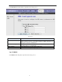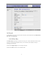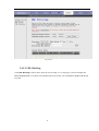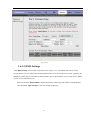
1
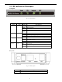
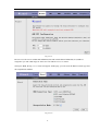
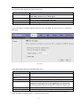
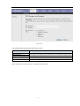
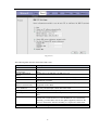
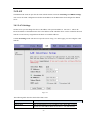
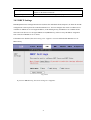
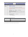
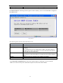
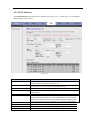
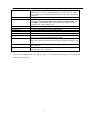
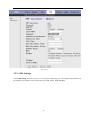
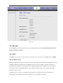
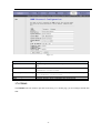
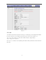
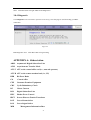
1 Port ADSL2+Router
User Manual
i
Contents
1. Introduction .................................................................................................................................................................. 1
1.1 Package List ........................................................................................................................................................ 1
1.2 Safety Cautions ................................................................................................................................................... 1
1.3 LED and Interface Description............................................................................................................................. 2
1.4 System Requirements .......................................................................................................................................... 3
1.5 Feature ................................................................................................................................................................ 3
1.6 FCC Compliance ................................................................................................................................................. 4
1.7 Supporting Protocols ........................................................................................................................................... 4
2. Hardware Installation .................................................................................................................................................... 5
3. Introducing Web Configuration ..................................................................................................................................... 7
3.1 How to access Router .......................................................................................................................................... 7
3.2 Status .................................................................................................................................................................. 8
3.2.1 System ...................................................................................................................................................... 8
3.2.2 LAN ......................................................................................................................................................... 9
3.2.3 WAN...................................................................................................................................................... 10
3.2.4 Statistic................................................................................................................................................... 10
3.2.4.1 Traffic Statistic..................................................................................................................................... 10
3.2.4.2 DSL Statistic........................................................................................................................................ 11
3.2.5 ARP Table .............................................................................................................................................. 12
3.3 Wizard .............................................................................................................................................................. 12
3.3.1 Wizard.................................................................................................................................................... 12
3.4 LAN.................................................................................................................................................................. 20
3.4.1 LAN Settings .......................................................................................................................................... 20
3.4.2 DHCP Settings........................................................................................................................................ 21
3.5 WAN ................................................................................................................................................................ 25
3.5.1 WAN Interface........................................................................................................................................ 26
3.5.2 ATM Settings ......................................................................................................................................... 28
3.5.3 ADSL Settings........................................................................................................................................ 29
3.6 Advance ............................................................................................................................................................ 30
3.6.1 DNS ....................................................................................................................................................... 30
3.6.1.1 DNS Server.......................................................................................................................................... 30
3.6.1.2 DDNS.................................................................................................................................................. 31
3.6.2 Firewall .................................................................................................................................................. 32
ii
3.6.2.1 IP\Port Filter ........................................................................................................................................ 32
3.6.2.2 MAC Filter .......................................................................................................................................... 33
3.6.2.3 URL Blocking...................................................................................................................................... 34
3.6.3 Virtual Server ......................................................................................................................................... 35
3.6.3.1 Services ............................................................................................................................................... 35
3.6.3.2 DMZ Settings....................................................................................................................................... 36
3.6.4 Routing................................................................................................................................................... 37
3.6.4.1 RIP ...................................................................................................................................................... 37
3.6.4.2 Static Route.......................................................................................................................................... 38
3.6.5 IP QoS .................................................................................................................................................... 39
3.6.6 Other ...................................................................................................................................................... 39
3.6.6.1 IGMP Proxy......................................................................................................................................... 40
3.6.6.2 UPNP................................................................................................................................................... 40
3.6.6.3 Bridge.................................................................................................................................................. 41
3.6.6.4 IP PassThrough .................................................................................................................................... 42
3.7 Admin ............................................................................................................................................................... 42
3.7.1 Remote Access........................................................................................................................................ 42
3.7.2 Commit/Reboot....................................................................................................................................... 43
3.7.3 Password................................................................................................................................................. 43
3.7.4 Backup/Restore....................................................................................................................................... 44
3.7.5 Upgrade Fireware.................................................................................................................................... 45
3.7.6 Time Zone .............................................................................................................................................. 45
3.7.7 SNMP..................................................................................................................................................... 46
3.7.8 TR069..................................................................................................................................................... 47
3.7.9 ACL ....................................................................................................................................................... 48
3.8 Diagnostic ......................................................................................................................................................... 49
3.8.1 Ping ........................................................................................................................................................ 49
3.8.2 ATM Loopback....................................................................................................................................... 50
3.8.3 ADSL ..................................................................................................................................................... 50
3.8.4 Diagnostic............................................................................................................................................... 51
APPENDIX B: Abbreviation ................................................................................................................................... 51
iii
1. Introduction
The ADSL access device supports multiple line modes. It provides one 10/100Base-T Ethernet interface at
the user end. Utilizing the high-speed ADSL connection, the device provide users with broadband
connectivity to the Internet or the Intranet for high-end users as net bars, office users, etc. can provide a
downlink speed up to 24 Mbit/s and uplink speed up to 1 Mbit/s.
1.1 Package List
l One single port router
l One external splitter
l One power adapter
l Two pieces of telephone lines(RJ-11,more than 1m)
l One piece of Ethernet cable(RJ-45, more than 1.5m)
l One copy of User’s Manual
l A centificate of quality
l One copy of driver and utility software CD(optional)
1.2 Safety Cautions
Follow these announcements below to pretect the device from risks and damage caused by fire or electric
power.
4 Use volume labels to mark the type of power.
4 Use the power adapter packed within the device package.
4 Pay attention to the power load of the outlet or prolonged lines. An overburden power outlet or
damaged lines and plugs may cause electric shock or fire accident. Check the power cords regularly. If
you find any damage, replace it at once.
4 Proper space left for heat radiation is necessary to avoid any damage caused by overheating to the
device. The long and thin holes on the Access Point are designed for heat radiation to make sure the
device works normally. Don’t cover these heat radiant holes.
4 Do not put this device close to a place where a heat source exits or high temperature occurs. Avoid the
device from direct sunshine.
4 Do not put this device close to a place where is over damp or watery. Do not spill any fluid on this
device.
4 Do not connect this device to any PC or electronic product, unless our customer engineer or your
broadband provider instructs you to do this, because any wrong connection may cause any power or fire
risk.
4 Do not place this device on an unstable surface or support.
1
1.3 LED and Interface Description
Front panel
Fig 1.3-1 Front panel
LED
POWER
Color
Green/Red
Status
Descriptions
OFF
No power
GREEN
Device init OK
Device init
Fireware upgrade
RED
RED
BLINK
Link
Green
ON
Initial self-test failed
Device is detecting itself
Initial self-test of the unit is OK and ready
OFF
Internet connection failed
BLINK
Internet data transiting
ON
Internet connection OK
OFF
No LAN link
BLINK
LAN data transiting
ON
LAN link established and active
OFF
BLINK
Data
Ethernet
Green
Green
Rear panel
Fig 1.3-2 Rear panel
Items
DSL
Usage
Line RJ-11 port
2
Items
Reset
Ethernet
PWR
Usage
Resets to factory defaults. To restore factory defaults, keep
the device powered on and push a paper clip in to the hole.
Press down the button over 5 seconds and then release.
Ethernet RJ-45 port
Power On/Off.
Power connector. DC 10 Voltage/1000mA,female pole is
positive.
1.4 System Requirements
Make sure first that you have prepared these following items to guarantee the ROUTER can work normally.
4 Services subscriptions
4 An 10BaseT/100BaseT Ethernet card installed on your PC
4 HUB or Switch. (Attached to several PCs through one of Ethernet interfaces on the device)
4 Operation system: Windows 98SE, Windows 2000, Windows ME, or Windows XP
4 Internet Explorer V5.0 or higher, or Netscape V4.0 or higher, or firefox 1.5 or higher.
1.5 Feature
4 Supports various line modes
4 Supports external PPPoE dial-up access
4 Supports internal PPPoE/PPPoA dial-up access
4 Supports leased line mode
4 Supports ZIPB (Zero Installation PPP Bridge Mode)
4 Supports 1483B/1483R/MER access
4 Supports multiple PVCs(eight at most) and these PVCs can be isolated from each other
4 Support a single PVC with multiple sessions
4 Support multiple PVCs with multiple sessions
4 Supports the binding of the ports and the PVCs
4 Supports the 802.1Q and 802.1P protocol
4 Supports DHCP server
4 Supports NAT/NAPT
4 Supports static route
4 Supports firmware upgrade:WEB/tftp/ftp
4 Supports reset to factory default:reset, WEB
4 Supports DNS relay
4 Supports Virtual server
4 Supports DMZ functions
4 Supports two-grade passwords and usernames
4 Supports WEB interface
4 Supports telnet CLI
4 Supports System status display
3
4 Supports PPP session PAP/CHAP
4 Supports IP filter function
4 Supports remote access control
4 Supports line connection status test
4 Supports remote management(Telnet; HTTP)
4 Supports configuration file backup and restoration function
4 Ethernet supported such as Crossover Detection & Auto-Correction and polarity correction
4 Supports UPnP
1.6 FCC Compliance
This equipment has been tested and found to comply with the limits for Class digital devices pursuant to
part 15 of the FCC Rules. These limits are designed to provide reasonable protection against harmful
interference when the equipment is operated in a commercial environment.
This equipment generates, uses, and can radiate radio frequency energy and, if not installed and used in
accordance with the instruction manual, may cause harmful interference to radio communication.
Operation of this equipment in residential area is likely to cause harmful interference in which case the user
will be required to correct the interference at this own expense.
The user should not modify or change this equipment without written approval from company name.
Modification could void authority to use this equipment.
For the safety reason, people should not work in a situation which RF Exposure limits be exceeded. To
prevent the situation happening, people who work with the antenna should be aware of the following rules:
1. Install the antenna in a location where a distance of 20cm from the antenna may be maintained.
2. While installing the antenna in the location, please do not turn on the power of wireless card.
3. While the device is working, please do not contact the antenna.
1.7 Supporting Protocols
ITU G.992.1 (G.DMT) Annex A
4 ITU G.992.2 (G.LITE)
4 ANSI T1.413 Issue 2
4 ITU G.992.3 (ADSL2)
4 ITU G.992.5 (ADSL2+)
4
2. Hardware Installation
1、Refer to the figure below: Connect the DSL port of the device and the ROUTER port of the splitter with
a telephone cable; connect the phone to the Phone port of the splitter through a cable; connect the incoming
line to the Line port of the splitter.
The splitter has three ports:
LINE: Connects to a wall phone jack (RJ-11 jack)
ROUTER: Connects to the DSL jack of the device
PHONE: Connects to a telephone set
2、Connect the LAN port of the device to the network card of the PC via an Ethernet line (MDI/MDIX).
Note: Use twisted-pair cables to connect with the HUB/Switch.
3、Plug the power adapter to the wall outlet and then connect the other end of it to the PWR port of the
device.
Connection 1: Fig. 2-1 displays the application diagram for the connection of the Router, PC, splitter and
telephone set。
Fig 2-1 Connection Diagram(Without connecting telephone sets before the splitter)
Connection 2:As illustrated in the following figure, the splitter is installed close to the device.
5
Fig 2-2 Connection Diagram(Connecting a telephone set before the splitter)
l
It is recommended to follow the Connection 1 in an actual connection!
l
Note: When Connection 2 is used, the filter must be installed close to the telephone lines. (See Fig.
2-2. Do not use the splitter instead of the filter).
Installing a telephone directly before the splitter may lead to a failure of connection between the device and
the device of LAN side, or cannot access into the Internet, or slow the connection speed if you really need to
add a telephone set before the splitter, you have to add a MicroFilter before connecting to a telephone set.
Do not connect several telephones before the splitter. Moreover, do not connect several telephones with
MicroFilters.
6
3. Introducing Web Configuration
3.1 How to access Router
The following introductions are prepared for the first time users, it is a detail “How-To” user
guide.
1、 Open IE browser,then enter http://192.168.1.1 in address bar.
2、 You are required to enter user name and password. See the Fig 3.2-1.
l
The super user name and password is admin/admin
l
The common user name and password is user/user
Fig 3.1-1
3、 If you enter as super user, the below screen will be displayed when you enter successfully.
7
Fig 3.1-2
After you enter router as super user, you can check, config and modify all the options. You can use the
system diagnostic function also.
If you enter as common user, you can check the status of ROUTER, but can’t change the most of options.
3.2 Status
Click Status in the menu to open the sub-menu which contains 5 items: System, LAN, WAN, Statistic and
ARP Table.
3.2.1 System
Click System in the sub-menu to open the screen of Fig 3.2.1. In this page, you can view the current status
and some basic settings of this router, for example, Software Version, DSL mode, Upstream Speed,
Downstream Speed, Uptime and so on.
8
Fig 3.2.1
3.2.2 LAN
Click LAN in the sub-menu to open the screen of Fig 3.2.2. In this page, you can view the LAN IP, DHCP
Server status, MAC Address and DHCP Client Table. If you want to config the LAN network, refer to
chapter 3.4.1 “LAN Settings”.
Fig 3.2.2
9
3.2.3 WAN
Click WAN in the sub-menu to open the screen of Fig 3.2.3. In this page, you can view basic status of WAN,
Default Gateway, DNS Server, ect. . If you want to config the WAN network, refer to chapter 3.5.1 “WAN
Interface”.
Fig 3.2.3
3.2.4 Statistic
Click Statistic in the sub-menu to open the menu in the left bar, whick contains two items:Traffic Statistic
and DSL Statistic.
3.2.4.1 Traffic Statistic
Click Traffic Statistic in the left bar to open the screen of Fig 3.2.4.1. In this page, you can view the
statistics of each network port.
10
Fig 3.2.4.1
3.2.4.2 DSL Statistic
Click DSL Statistic in the left bar to open the screen of Fig 3.2.4.2. In this page, you can view the
ADSL line statistics, downstream rate, upstream rate, ect. .
Fig 3.2.4.2
11
3.2.5 ARP Table
Click ARP Table in the sub-menu to open the screen of Fig 3.2.5. In this page, you can view the talbe
which shows a list of learned MAC addresses.
Fig 3.2.5
3.3 Wizard
Click Wizard in the menu to open the sub-menu which contains one item: Wizard.
3.3.1 Wizard
Wizard enables speedy and accurate configuration of your Internet connection and other important
parameters. The following sections describe these various configuration parameters. Whether you configure
these parameters or use the default ones, click 'Next' to enable your Internet connection.
When subscribing to a broadband service, you should be aware of the method by which you are connected
to the Internet. Your physical WAN device can be either Ethernet, DSL, or both. Technical information
regarding the properties of your Internet connection should be provided by your Internet Service Provider
(ISP). For example, your ISP should inform you whether you are connected to the Internet using a static or
dynamic IP address, or what protocols, such as PPPOA or PPPoE, you will be using to communicate over
the Internet.
Click Wizard in the sub-menu to open the screen of Fig 3.3.1-1. In this page, you can config the VPI/VCI
number.
12
Fig 3.3.1-1
Be sure to use the correct Virtual Path Identifier(VPI) and Virtual Channel Identifier(VCI) numbers
assigned to you. The valid range for VPI is 0 to 255 and for VCI is 1 to 65535.
Then press Next, the Fig 3.3.1-2 screen will appear. In this page, you can select the WAN Connect Type and
the encapsulation method.
Fig 3.3.1-2
13
The following table describes the fields in this screen.
Label
Description
WAN Connection Type
Select the WAN Connection Type here, you can select PPPoA, PPPoE,
1483 MER, 1483 Routed or 1483 Bridged.
Select the method of encapsulation used by your ISP from the drop-down
list box. Choises are LLC/SNAP or VC-Mux.
Click < Back to return to the previous screen
Click Next > to go to the next screen
Encapsulation Mode
< Back
Next >
If you select PPPoA or PPPoE in WAN Connection Type, click Next, the screen of Fig 3.3.1-3 appears as
shown next.
Fig 3.3.1-3
The following table describes the fields of this screen.
Label
Description
Obtain an IP address
automatically
Use the following IP
address
WAN IP Address
Enable NAT
The dynamic IP is not fixed; your ISP assigns you the different one each
time.
A static IP is a fixed IP that your ISP gives you.
< Back
Next >
Input the IP address of the WAN interface provided by your ISP
Select it to enable the NAT functions of the MODEM. If you are not to
enable NAT and intend the user of the MODEM to access the Internet
normally, you must add a route on the uplink equipment; otherwise the
access to the Internet will fail. Normally, it is required to enable NAT.
Click < Back to return to the previous screen
Click Next > to go to the next screen
Then click Next, the screen of Fig3.3.1-4 appears as shown next.
14
Fig 3.3.1-4
The following table describes the fields of this screen.
Label
Description
PPP Username
PPP Password
PPP Connection Type
< Back
Next >
The username and password apply to PPPoE and PPPoA encapsulation
only. Make sure that you have entered the correct username and password.
Choices are Continuous, Connect on Demand and Manual.
Click < Back to return to the previous screen
Click Next > to go to the next screen
Then click Next, the screen of Fig3.3.1-5 appears as shown next.
15
Fig 3.3.1-5
The following table describes the fields of this screen.
Label
Description
LAN IP
Enter the IP address of your ROUTER in dotted decimal notation, for
example, 192.168.1.1(factory default)
Type the subnet mask of LAN IP.
Select this check box to enable the secondary LAN IP
Enter the secondary IP address of your ROUTER in dotted decimal
notation, for example, 192.168.100.1(factory default)
Type the subnet mask of the secondary LAN IP
Select this check box to enable the DHCP Server
This field specifies the first of the contiguous addresses in the IP address
pool.
This field specifies the last of the contiguous addresses in the IP address
pool.
Click < Back to return to the previous screen
Click Next > to go to the next screen
LAN Netmask
Enable Secondary IP
Secondary LAN IP
Secondary LAN Netmask
Enable DHCP Server
Start IP
End IP
< Back
Next >
If you finish the settings of this page, click Next, the screen appears as shown next.
16
Fig 3.3.1-7
If you select 1483 MER in Fig 3.3.1-2, the screen appears as shown next.
Fig 3.3.1-8
17
The following table describes the fields of this screen.
Label
Description
Obtain an IP address
automatically
The MODEM will obtain a (WAN) IP address automatically and at this
time it will enable DHCP Client functions. The WAN IP address is
obtained from the uplink equipment like BAS and the uplink equipment is
required to enable the DHCP Server functions.
If you want to input the WAN ip address by yourself. Check this entry and
then input related data in the field.
Input the IP address of the WAN interface provided by your ISP
Input the subnet mask concerned to the IP address of the WAN interface
provided by your ISP.
You can input the IP address of the default gateway by yourself, click this
entry and then input related data in the fields.
To obtain the IP address of the DNS server assigned by the uplink
equipment such as BAS.
If you want to input the IP address of the DNS server by yourself, click
this entry and then input related data in the fields.
Input the IP address of the primary DNS server here.
Input the IP address of the secondary DNS server provided by your ISP
here.
Select it to enable the NAT functions of the MODEM. If you are not to
enable NAT and intend the user of the MODEM to access the Internet
normally, you must add a route on the uplink equipment; otherwise the
access to the Internet will fail. Normally, it is required to enable NAT.
Click < Back to return to the previous screen
Click Next > to go to the next screen
Use the following IP
address
WAN IP Address
WAN Subnet Mask
Default Gateway
Obtain DNS server
addresses automatically
Use the following DNS
server addresses
Primary DNS server
Secondary DNS server
Enable NAT
< Back
Next >
If you finish the settings of this page, click Next, the screen of Fig 3.3.1-6 appears. The settings of this
screen, see above paragraphs.
If you select 1483 Routed in Fig 3.3.1-2, the screen of Fig 3.3.1-9 appears as shown next.
18
Fig 3.3.1-9
The following table describes the fields of this screen.
Label
None
Obtain an IP address
automatically
Use the following IP
address
WAN IP Address
WAN Subnet Mask
Obtain DNS server
addresses automatically
Use the following DNS
server addresses
Primary DNS server
Secondary DNS server
Enable NAT
< Back
Next >
Description
The dynamic IP is not fixed; your ISP assigns you the different one each
time.
A static IP is a fixed IP that your ISP gives you.
Input the IP address of the WAN interface provided by your ISP
Input the subnet mask concerned to the IP address of the WAN interface
provided by your ISP.
To obtain the IP address of the DNS server assigned by the uplink
equipment such as BAS.
If you want to input the IP address of the DNS server by yourself, click
this entry and then input related data in the fields.
Input the IP address of the primary DNS server here.
Input the IP address of the secondary DNS server provided by your ISP
here.
Select it to enable the NAT functions of the MODEM. If you are not to
enable NAT and intend the user of the MODEM to access the Internet
normally, you must add a route on the uplink equipment; otherwise the
access to the Internet will fail. Normally, it is required to enable NAT.
Click < Back to return to the previous screen
Click Next > to go to the next screen
19
3.4 LAN
Click LAN in the menu to open the sub-menu which contains 2 items: LAN Settings and DHCP Settings.
You can use the LAN configuration to define an IP address for the DSL Router and configure the DHCP
server.
3.4.1 LAN Settings
On this screen you can change the device's IP address. The preset IP address is 192.168.1.1. This is the
Private IP address of the DSL Router. This is the address under which the device can be reached in the local
network. It can be freely assigned from the block of available addresses.
Click LAN Settings in the sub-menu to open the screen of Fig 3.4.1. In this page you can config the LAN
network.
Fig 3.4.1
The following table describes the fields of this screen.
Label
Description
IP Address
Subnet Mask
Input the IP of Local area network interface here.
We recommend that you use an address from a block that is reserved for
private use. This address block is 192.168.1.1- 192.168.255.254
20
Secondary IP
Apply Changes
Select this checkbox to enable the secondary LAN IP. The two LAN IP
must be in the different network.
Click this button to save the settings of this page.
3.4.2 DHCP Settings
DHCP(Dynamic Host Configuration Protocol) allows the individual client(computers) to obain the TCP/IP
configuration at start-up from the centralize DHCP server. You can configure this router as a DHCP server
or disable it. DHCP server can assign IP address, an IP default gateway and DNS server to DHCP clients.
This router can also act as a surrogate DHCP server(DHCP Proxy) where it relays IP address assignment
from a actual real DHCP server to clients.
If the DHCP was disabled, the screen of Fig 3.4.2-1 appears. You can enable/disable DHCP Server or
DHCP Proxy.
Fig 3.4.2-1
If you set to DHCP Proxy, the screen of Fig 3.4.2-2 appears.
21
Fig 3.4.2-2
The following table describes the fields of this screen.
Label
Description
DHCP Proxy
If set to DHCP Proxy, your ROUTER acts a surrogate DHCP Server and
relays the DHCP requests and reponses between the remote server and the
client.
Enter the IP address of the actual, remote DHCP server in this field.
Click this button to save the changes of this page.
DHCP Server Address
Apply Changes
If you set to DHCP Server, the screen of Fig3.4.2-3 appears as shown next.
22
Fig 3.4.2-3
The following table describes the fields in this screen.
Label
Description
DHCP Server
If set to DHCP Server, your ROUTER can assign IP addresses, an IP
default gateway and DNS Servers to Windows95, Windows NT and other
systems that support the DHCP client.
This field specifies the first and the last of contiguous IP address of the IP
address pool.
Click this button, the screen of Fig 3.5.2-4 appears, which shows the
assigned IP address of the clients.
The Lease time determines the period for which the PCs retain the IP
addresses assigned to them without changing them.
Input the domain name here if you know. If you leave this blank, the
domain name obtained by DHCP from the ISP is used. While you must
enter host name(System Name) on each individual computer, the domain
name can be assigned from this router via DHCP server.
Enter the IP default gateway of the IP address pool.
Click this button, the screen of Fig3.5.2-5 appears. This function allows
you assign IP addresses on the LAN to specific individual computers
based on their MAC address.
IP Pool Range
Show Client
Max Lease Time
Domain Name
Gateway Address
MAC-Base Assignment
23
Apply Changes
Click this button to save the changes of this page.
Click Show Client, the following window appears. In this window, you can view the IP address assigned to
each DHCP client.
Fig 3.4.2-4
The following table describes the fields in this screen.
Label
Description
IP Address
MAC Address
This field displays the IP address relative to the MAC address.
This field displays the MAC(Media Access Control) address of the
computer.
Every Ethernet device has a unique MAC address. The MAC address is
assigned at the factory and consists of six pairs of hexadecimal character,
for example, 00-A0-C5-00-02-12.
Here shows the lease time. The Lease time determines the period for
which the PCs retain the IP addresses assigned to them without changing
them.
Click this button to refresh the Active DHCP Client Table.
Click this button to close this window.
Time Expired(s)
Refresh
Close
Click MAC-Base Assignment button, the below window appears. In this page, you can assign IP
addresses on the LAN to specific individual computers based on their MAC address.
24
Fig 3.4.2-5
The following table describes the fields of this screen.
Label
Description
Host MAC Address
Assigned IP Address
Assign IP
Type the MAC address of a computer on your LAN
This field specifics the IP of the IP address pool.
Click this button after entered Host MAC Address and Assigned IP
Address, a row will be added in MAC-Base Assignment Table.
Select a row in MAC-Base Assignment Table, the MAC address and IP
address will appears Host MAC Address and Assigned IP Address.
After modified the MAC Address and IP Address, click this button to save
the changes.
Select a row in MAC-Base Assignment Table, then click this button, this
row will be deleted.
Click this button to close this window.
This table shows the assigned IP address based on the MAC address.
Modify Assigned IP
Delete Assigned IP
Close
MAC-Base Assignment
Table
3.5 WAN
Click WAN Interface in the menu to open the sub-menu which contains 3 items: WAN Interface、ATM
Settings and ADSL Settings.
25
3.5.1 WAN Interface
Click WAN Interface in the sub-menu to open the screen of Fig 3.5.1-1. In this page, you can configure
WAN Interface of your router.
Fig 3.5.1-1
Label
Description
VPI
(Virtual Path Identifier) The virtual path between two points in an ATM
network, and its valid value is from 0 to 255
The virtual channel between two points in an ATM network, ranging from
32 to 65535 (1 to 31 are reserved for known protocols)
Choices are LLC and VC-Mux.
There are five choices: 1483 Bridged, 1483 MER, PPPoE, PPPoA and
1483 Routed.
If select Disable, this PVC will be unusable.
Select it to enable the NAPT functions of the MODEM. If you are not to
enable NAPT and intend the user of the MODEM to access the Internet
normally, you must add a route on the uplink equipment; otherwise the
access to the Internet will fail. Normally, it is required to enable NAPT.
VCI
Encapsulation
Channel Mode
Admin Status
Enable NAPT
PPP Settings
Login Name
Password
Connection Type
The correct user name that your ISP has provided to you.
The correct password that your ISP has provided to you
The choices are Continuous, Connect on Demand and Manual.
26
Idle Time(min)
WAN IP Settings
Type
Local IP Address
Remote IP Address
Subnet Mask
Unnumbered
Default Route
Add
Modify
Delete Selected
If select Connect on Demand, you need to input the idle timeout time.
Within the preset minutes, if the MODEM doesn’t detect the flow of the
user continuously, the MODEM will automatically disconnect the PPPOE
connection.
The choices are Fixed IP and Use DHCP. If set Fixed IP, you should
enter the Local IP Address, Remote IP Address and Subnet Mask. If set
Use DHCP, your MODEM will be a DHCP client, the WAN IP will be
assigned by the remote DHCP server.
This is the IP of WAN interface which is provided by your ISP.
This is the gateway IP which is provided by your ISP.
This is the Subnet Mask of the Local IP Address.
Select this checkbox to enable IP Unnumbered function.
After configuring the parameters of this page, click this button then a new
PVC will be added into Current ATM VC Table.
Select a PVC in the Current ATM VC Table, then modify the parameters
of this PVC. When you finish, click this button to apply the change of this
PVC.
Select a PVC in the Current ATM VC Table, then click this button to
delete this PVC.
Click this button, the following screens will appear. In these pages, you
can modify the PVCs’ parameters.
If the PVC uses PPPoE mode, click
, the Fig 3.5.1-2 will appear. In this page, you can configure this
PPPoE PVC’s parameters.
27
Fig 3.5.1-2
3.5.2 ATM Settings
Click ATM Setting, the screen of Fig 3.5.1-3 will appear. In this page, you can configure the parameters of
the ATM for your ADSL router, include QoS type, PCR, CDVT, SCR and MBS.
28
Fig 3.5.1-3
3.5.3 ADSL Settings
Click ADSL Interface in the sub-menu to open the screen of Fig 3.5.2. In this page, you can select the DSL
modulation. Mostly, the user just need to remain this factory default setting. Our modem support these
modulations: G.Dmt, G.lite, T1.413, ADSL2, ADSL2+, AnnexL and AnnexM. The router will negotiate
the modulation mode with the DSLAM.
29
Fig 3.5.2
3.6 Advance
Click Advance in the menu to open the sub-menu which contains 6 items: DNS, Firewall, Virtual Server,
Routing, IP QOS, and Others.
3.6.1 DNS
Click DNS in the sub-menu to open the menu in the left bar, whick contains two items:DNS Server and DDNS.
3.6.1.1 DNS Server
Short for Domain Name System (or Service or Server), an Internet service that translates domain names into
IP addresses. Because domain names are alphabetic, they're easier to remember. The Internet however, is
really based on IP addresses. Every time you use a domain name, therefore, a DNS service must translate
the name into the corresponding IP address. For example, the domain name www.example.com might
translate to 198.105.232.4.
The DNS system is, in fact, its own network. If one DNS server doesn't know how to translate a particular
domain name, it asks another one, and so on, until the correct IP address is returned.
30
Click DNS Server in the left bar to open the screen of Fig 3.6.1.1.
Fig 3.6.1.1
Label
Description
Attain DNS Automatically
When this checkbox is selected, this router will accept the first received
DNS assignment from one of the PPPoA, PPPoE or MER enabled PVC(s)
during the connection establishment.
When this checkbox is selected, please enter the primary and optional
secondary DNS server IP addresses.
Click this button to save the settings of this page.
Click this button to begin configuring this screen afresh.
Set DNS Manually
Apply Changes
Reset Selected
3.6.1.2 DDNS
Click DDNS in the left pane to open the screen of Fig 3.6.1.2.
31
Fig 3.6.1.2
3.6.2 Firewall
Click Firewall in the sub-menu to open the menu in the left bar, whick contains three items:IP\Port Fileter,
MAC Filter and URL Blocking.
3.6.2.1 IP\Port Filter
Click IP\Port Filter in the left bar to open the screen of Fig 3.6.2.1. Entries in this table are used to restrict
certain types of data packets through the Gateway. Use of such filters can be helpful in securing or
restricting your local network.
Click the button Apply Changes to save the settings of this page.
Click the button Add to add a new rule of the IP\Port Filter.
32
Fig 3.6.2.1
3.6.2.2 MAC Filter
Click MAC Filter in the left bar to open the screen of Fig 3.6.2.2. Entries in this table are used to restrict
certain types of data packets from your local network to Internet through the Gateway. Use of such filters
can be helpful in securing or restricting your local network.
Click the button Apply Changes to save the settings of this page.
Click the button Add to add a new rule of the MAC Filter.
33
Fig 3.6.2.2
3.6.2.3 URL Blocking
Click URL Blocking in the left bar to open the screen of Fig 3.6.2.3. This page is used to configure the
Blocked FQDN(Such as tw.yahoo.com) and filtered keyword. Here you can add/delete FQDN and filtered
keyword.
34
Fig 3.6.2.3
3.6.3 Virtual Server
Click Virtual Server in the sub-menu to open the menu in the left bar,whick contains two items:Services
and DMZ Settings.
3.6.3.1 Services
Click Services in the left pane to open the screen of Fig 3.6.3.1. This page is used to enable the servers in
the local network.
Click the button Add to add a virtual server.
35
Fig 3.6.3.1
3.6.3.2 DMZ Settings
Click DMZ Settings in the left bar to open the screen of Fig 3.6.3.2. A Demilitarized Zone is used to
provide Internet services without sacrificing unauthorized access to its local private network. Typically, the
DMZ host contains devices accessible to Internet traffic, such as Web (HTTP ) servers, FTP servers, SMTP
(e-mail) servers and DNS servers.
Select the checkbox Enable DMZ to enable this function. Then input a IP Address of the DMZ host.
Click the button Apply Changes to save the settings of this page.
36
Fig 3.6.3.2
3.6.4 Routing
Click Routing in the sub-menu to open the menu in the left bar, whick contains two items:RIP and Static
Route.
3.6.4.1 RIP
Click RIP in the left bar to open the screen of Fig 3.6.4.1. Enable the RIP if you are using this device as a
RIP-enabled router to communicate with others using the Routing Information Protocol. This page is used
to select the interfaces on your deviceis that use RIP, and the version of the protocol used.
37
Fig 3.6.4.1
3.6.4.2 Static Route
Click Static Route in the left bar to open the screen of Fig 3.6.4.2-1. This page is used to configure the
routing information. Here you can add/delete IP routes.
Fig 3.6.4.2-1
Click the button Show Routes, the below window will appear. The table shows a list of destination
routes commonly accessed by your network.
Fig 3.6.4.2-2
38
3.6.5 IP QoS
Click IP QoS in the sub-menu to open the screen of Fig 3.6.5. Entries in this table are used to assign the
precedence for each incoming packet based on physical LAN port, TCP/UDP port number, and
source/destination IP address/subnet masks.
Click the button Apply Changes to save the settings of this page.
Fig 3.6.5
3.6.6 Other
Click Others in the sub-menu to open the menu in the left bar,whick contains four items:IGMP Proxy,
UPNP,
Bridge and IP PassThrough.
39
3.6.6.1 IGMP Proxy
Click IGMP Proxy in the left bar to open the screen of Fig 3.6.6.1. IGMP proxy enables the system to issue
IGMP host messages on behalf of hosts that the system discovered through standard IGMP interfaces. The
system acts as a proxy for its hosts after you enable it.
Click Apply Changes to save the settings of this page.
Fig 3.6.6.1
3.6.6.2 UPNP
Click UPNP in the left bar to open the screen of Fig 3.6.6.2. This page is used to configure UPnP. The
system acts as a daemon after you enable it.
Click Apply Changes to save the settings of this page.
40
Fig 3.6.6.2
3.6.6.3 Bridge
Click Bridge in the left bar to open the screen of Fig 3.6.6.3-1. This page is used to configure the bridge
parameters. Here you can change the settings or view some information on the bridge and its attached ports.
Fig 3.6.6.3-1
Click Show MACs button in Fig 3.6.6.3-1, the below window will appear. This table shows a list of
learned MAC addresses for this bridge.
Fig 3.6.6.3-2
41
3.6.6.4 IP PassThrough
Click IP PassThrough in the left bar to open the screen of Fig 3.6.6.4. The IP PassThrough has the other
name ZIPB or IP Extension. In this page, you can enable and configure IP PassThrough function.
Fig 3.6.6.4
3.7 Admin
Click Admin in the menu to open the sub-menu which contains 9 items: Remote Access, Commit/Reboot,
Password, Backup/Restore, Upgrade Fireware, Time Zone, SNMP ,TR069 and ACL.
3.7.1 Remote Access
Click Remote Access in the sub-menu to open the screen of Fig 3.7.1. In this page, you can enable or
disable the services which will be used by remote host. For example, if TELNET service is enabled and port
is 23, the remote host can access this router by telnet through port 23.
42
Fig 3.7.1
3.7.2 Commit/Reboot
Click Commit/Reboot in the sub-menu to open the screen of Fig 3.7.2. In this page, you can set the router
reboot to default settings or set the router save the current settings then reboot.
Fig 3.7.2
Label
Description
Restore to Factory
Default Setting
Save Current Setting
System Reboot
Select this checkbox to reset router to default settings.
Select this checkbox to save the current settings and reboot router.
Click this button to reboot the router according to the above option.
3.7.3 Password
Click Password in the sub-menu to open the screen of Fig 3.7.3. In this page, you can change the password
of the user, include admin and user. The super user name and password are admin/admin as default, and the
The common user name and password are user/user.
43
Fig 3.7.3
Label
Description
User Name
Select the user name in the drop-down list box. The choices are admin
and user.
After selected the user name, input the old password of the user here.
Input the new password what you want to set of the user.
Input the new password again.
Click this button to save the settings of this page.
Click this button to begin configuring the password afresh.
Old Password
New Password
Confirmed Password
Apply Changes
Reset
3.7.4 Backup/Restore
Click Backup/Restore in the sub-menu to open the screen of Fig 3.7.4. In this page, you can backup the
current settings to a file and restore the settings from the file which was saved previously.
IMPORTANT! Do not turn off your router or press the Reset button while these procedures are in
progress.
Fig 3.7.4
44
Label
Description
Save Settings to File
Click the Save button, then select the path and save the configuration file
of your router.
Click the Browse button to select the configuration file.
Selected the configuration file of router, click Upload button to begin
restore the router configuration.
Load Settings from File
Upload
3.7.5 Upgrade Fireware
Click Upgrade Fireware in the sub-menu to open the screen of Fig 3.7.5. In this page, you can upgrade the
fireware of this router.
IMPORTANT! Do not turn off your router or press the Reset button while this procedure is in progress.
Fig 3.7.5
Label
Description
Select File
Upload
Click the Browse button to select the Fireware file.
Selected the Fireware file, click Upload button to begin upgrading the
Fireware.
Click this button to begin selecting the Fireware file afresh.
Reset
3.7.6 Time Zone
Click Time Zone in the sub-menu to open the screen of Fig 3.7.6. In this page, you can set the system time
manually or get the system time from the time server.
45
Fig 3.7.6
Label
Description
Refresh
Time Mode
Click this button to refresh the system shown in the page.
If select Time Server, the router will get the system time from the time
server. If select Manual, you should configure the system time manually.
If select this checkbox, you can choose the correct SNTP Server which
you want.
Choose the SNTP Server here.
Select the Time Zone of in which area you are.
Click this button to save the settings of this page.
Enable SNTP Client
Update
SNTP Server
Time Zone
Apply Changes
3.7.7 SNMP
Click SNMP in the sub-menu to open the screen of Fig 3.7.7. In this page, you can set the SNMP
parameters.
46
Fig 3.7.7
Label
Description
Trap IP Address
Input the Trap Host’s IP here. The trap information will be sent to this
host.
The network administrators must use this password to read the
information of this router.
The network administrators must use this password to configure
the information of this router.
Click this button to save the settings of this page.
Click this button to begin configuring this screen afresh.
Community name(read-only)
Community name(write-only)
Apply Changes
Reset
3.7.8 TR069
Click TR069 in the sub-menu to open the screen of Fig 3.7.8. In this page, you can configure the TR-069
CPE.
47
Fig 3.7.8
3.7.9 ACL
Click ACL in the sub-menu to open the screen of Fig 3.7.9. In this page, you can configure the IP Address
for Access Control List. If ACL enabled, only the effective IP in ACL can access ADSL Router.
Step 1: If you want to enable ACL, please choose "Enable" then press "Apply Changes";
Step 2: Config Access Control List;
Note: If you check "Enable" in ACL Capability, please make sure that your host IP is in ACL List before it
takes effect
48
Fig 3.7.9
3.8 Diagnostic
Click Diagnostic in the menu to open the sub-menu which contains 4 items: Ping, ATM Loopback, ADSL
and Diagnostic.
3.8.1 Ping
Click Ping in the sub-menu to open the screen of Fig 3.8.1.
Fig 3.8.1
Label
Description
Host Address
Go!
Enter the IP Address here.
Click this button to begin to Ping the Host Address.
49
3.8.2 ATM Loopback
Click ATM Loopback in the sub-menu to open the screen of Fig 3.8.2. In this page, you can use VCC
loopback function to check the connectivity of the VCC.
Fig 3.8.2
Go!:Click this button to begin testing.
3.8.3 ADSL
Click ADSL in the sub-menu to open the screen of Fig 3.8.3. This page is used for ADSL Tone Diagnostics.
Fig 3.8.3
50
Start:Click this button to begin ADSL Tone Diagnostics.
3.8.4 Diagnostic
Click Diagnostic in the sub-menu to open the screen of Fig 3.8.4. This page is used for testing your DSL
connection.
Fig 3.8.4
Run Diagnostic Test:Click this button to begin testing.
APPENDIX A: Abbreviation
ADSL Asymmetric Digital Subscriber Line
ATM
Asynchronous Transfer Mode
ATU C ATU at the central office end (i.e., network operator)
ATU R ATU at the remote terminal end (i.e., CP)
BER
Bit Error Ratio
CO
Central office
CPE
Customer Premises Equipment
CRC
Cyclic Redundancy Check
DC
Direct Current
DSL
Digital Subscriber Line
HEC
Header Error Control
IDFT
Inverse Discrete Fourier Transform
LOF
Loss-of-frame defect
LOS
Loss-of-signal defect
MIB
Management Information Base
51
Modem (MOdulator, DEModulator)
NMS
Network Management System
OAM
Operations, Administration and Maintenance
POTS Plain old telephone service; one of the services using the voiceband; sometimes used
as a descriptor for all voiceband services
PSTN
PVC
Public Switched Telephone Network
Persist Virtual Circuit
QAM
Quadrature Amplitude Modulation
SNR
Signal to Noise Ratio
TP
Twisted Pair
VPN
Virtual Private Network
52