1
COMPIX® 221
Thermal Imaging System
Installation and Operating Instructions
Version 1.3
1/8/2008
NOTICE
This manual is intended solely to provide instructions for operation of the Compix 221 Thermal Imaging
System and its accompanying Thermal Evaluation Software. Compix reserves the right to change the
information contained in this manual without notice. No warranty, expressed or implied, is made
regarding the accuracy of the information in this manual at any time following its release or for any
purpose other than as a guide to operation of Compix Systems.
Copyright 2007 by Compix Incorporated, Tualatin, Oregon. All rights reserved.
Compix is a registered trademark of Compix Incorporated. IBM is a registered trademark of International
Business Machines Corp. Microsoft, Windows XP are trademarks or registered trademarks of Microsoft
Corporation. All other brand and product names are trademarks or registered trademarks of their
respective companies.
Table of Contents
1. INTRODUCTION.................................................................................................................................................. 3
2. SYSTEM DESCRIPTION AND OPERATING REQUIREMENTS ................................................................ 4
3. INSTALLATION AND SET UP .......................................................................................................................... 5
SOFTWARE INSTALLATION......................................................................................................................................... 5
TES Installation .................................................................................................................................................... 5
USB driver installation ......................................................................................................................................... 5
HARDWARE INSTALLATION ....................................................................................................................................... 5
Connecting the Camera ........................................................................................................................................ 5
PREPARING TO TAKE IMAGES ..................................................................................................................................... 6
IMAGE TOUCHUP ....................................................................................................................................................... 6
TES SOFTWARE OVERVIEW ...................................................................................................................................... 7
5. OPERATING SUGGESTIONS............................................................................................................................ 8
FOCUSING .................................................................................................................................................................. 8
FRAMING OR DETERMINING WHAT IS BEING VIEWED ............................................................................................... 8
PRINTING AND EXPORTING IMAGES............................................................................................................................ 9
6. MAINTENANCE................................................................................................................................................. 11
CALIBRATION .......................................................................................................................................................... 11
CLEANING ............................................................................................................................................................... 11
STORAGE AND TRANSPORTING................................................................................................................................. 11
REPACKAGING FOR SHIPMENT ................................................................................................................................. 11
7. USER SUPPORT ................................................................................................................................................. 12
8. COMPIX 221 LIMITED WARRANTY ........................................................................................................... 13
SHIPPING.................................................................................................................................................................. 13
APPENDIX A.
ACCESSORIES ........................................................................................................................ 14
TRIPOD .................................................................................................................................................................... 14
TABLE TOP STAND ................................................................................................................................................... 15
MEDICAL TRIPOD ..................................................................................................................................................... 15
HEAVY DUTY TABLE TOP STAND .............................................................................................................................. 16
APPENDIX B.
EFFICIENCY, EMISSIVITY, LENS FACTOR, AND NOISE............................................... 18
EMISSIVITIES OF COMMON ELECTRONIC MATERIALS................................................................................................ 19
1. INTRODUCTION
The Compix® 221 (hereafter referred to as 221) will work with any Windows XP based computer. The
221A requires a USB 2.0 port. It is designed for non-contact mapping and measuring of surface
temperatures. The heart of the system is a sophisticated camera that is sensitive to infrared (IR)
radiation. This camera is a reliable, cost-effective tool that provides fast, comprehensive evaluations of
thermal performance.
Since elevated temperatures are often cited as a cause of failure in electronic products, thermal
phenomena are of particular interest to design and reliability engineers.
An example application of the 221 is the study of temperature distribution and heat flow on electronic
circuit boards. In an energized electronic circuit, power is dissipated as heat that produces radiant
infrared (IR) energy. The 221 captures this radiation and produces a two-dimensional map, or thermal
image, of the object's surface temperatures.
All configurations of the 221 thermal imagers come with Thermal Evaluation Software, typically
“
WinTES2”(
her
eaf
t
erreferred to as TES), for camera control, image storage, and display. TES provides
the graphical user interface (GUI) as well as the interface that permits the computer to communicate with
the Compix IR Camera. TES lets the operator adjust the display, compare images, change colormaps,
compensate for different emissivities, read temperatures at specific locations, compute area statistics,
and show thermal profiles. An important feature of TES is the use of the industry standard TIFF image
file format for storing thermal images. This makes it easy to use the images with other software
programs. A second format for image storage is the Compix format (cpx). This format stores the full 32bit range of temperature data. It is larger than the TIFF file format (192k vs. 95k) and is readable only
with Compix software such as TES or Reporter.
The rest of this manual describes the 221 series thermal imagers and their operation in more detail.
NOTE
Before attempting to operate the system you should read sections 2. SYSTEM DESCRIPTION AND
OPERATING REQUIREMENTS, 3. INSTALLATION AND SET UP, and 4. MAKING THERMAL
IMAGES.
2. SYSTEM DESCRIPTION and OPERATING REQUIREMENTS
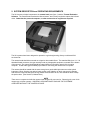
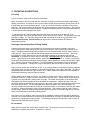
The 221 has two principal components: the camera head (see figure 1) and the Thermal Evaluation
Software. The camera head contains the infrared sensor, and circuitry required to capture the infrared
video. Other than the personal computer, no other accessories or supplies are required.
Figure 1
The 221 systems have been designed to operate in a typical engineering, factory or sheltered field
environments.
Thecamer
aheadshoul
dbemount
edonat
r
i
podorot
herst
abl
ef
i
x
t
ur
e.Thest
andar
df
i
t
t
i
ngi
sa1/
4“
- 20
threaded female connector, the type normally found on photographic equipment, mounted on the bottom
of the camera. The camera head should be located within ten feet (three meters) of the imaging
computer. A USB cable (type A/B M/M) is provided for connecting the camera to the computer.
The camera should be treated with the same care given a good visible light camera or other optical
instrument. Minor vibration can reduce image quality; major vibration or shock may result in damage.
And while the longer wavelength IR energy makes it less sensitive to dirt, care should be taken to keep
the optics clean. (See Section 8, Maintenance.)
NOTE
There are no components inside the camera head designed for user service. Removing the cover of the
camera may void the warranty. UNDER NO CIRCUMSTANCES SHOULD THE SYSTEM BE
OPERATED WITHOUT THE COVERS IN PLACE.
3. INSTALLATION AND SET UP
Unpack the system. Inspect the system for physical damage. If you find shipping damage, stop, inform
the carrier and call Compix Customer Service. If possible, store the shipping carton and packing
materials for future use.
There are two distinct steps in the installation procedure: software installation; camera connection
and set-up. You should perform all of these steps before proceeding to the verification phase.
NOTE
You may install TES on additional computers to allow others to view images. TES will run without a
camera thus letting you load, display and manipulate previously stored images.
Software Installation
TES Installation
The TES software is distributed on a CD-ROM. The software has been designed to work with personal
computers running Windows XP. For installation and operation instructions on TES software, refer to the
‘
i
nst
al
l
i
nst
r
uct
i
ons’
l
ocat
edi
nt
her
ootdi
r
ect
or
yoft
heTESdi
st
r
i
but
i
onmedi
a.
USB driver installation
Upon connecting power and the USB to a camera for the first time, the computer will request that drivers
be installed. Follow the instructions presented by the computer to complete this process. For current
r
el
ev
antdet
ai
l
s,r
ef
ert
o‘
i
nst
al
l
i
nst
r
uct
i
ons’
l
ocated in the root directory of the TES distribution media.
Hardware Installation
NOTE
Software must be installed before installing hardware unless otherwise stated in the software installation
not
es.Pl
easecheck‘
i
nst
al
l
i
nst
r
uct
i
ons’
l
ocat
edi
nt
heroot directory of the software installation media.
Connecting the Camera
The camera can either sit on a level surface or be mounted to a tripod or stand. Follow instructions in
Appendix A for appropriate mounting options below:
tripod
table top stand
heavy duty table top stand
CAUTION
The DC power input circuitry of the 221 is rated to accommodate up to 6 VDC. A power
input voltage in excess of this value may permanently damage the electronics in the
camera.
Connect the 5V desktop supply to a suitable source of 110-250VAC 50-60 Hz power and the low voltage
output cable coming from the supply to the DC power jack on the rear of the camera. Connect t
he“
B”
pl
ug(
t
henar
r
oweroft
het
woends)oft
heUSBcabl
et
ot
her
earoft
he220camer
a.Connectt
he“
A”pl
ug
oft
heUSBcabl
et
oanav
ai
l
abl
e“
A”r
ecept
acl
eony
ourPC.I
ft
her
ei
sapr
ot
ect
i
v
ecapcov
er
i
ngt
hel
ens
of the camera, make sure to remove i
tbef
or
ei
magi
ng.Ref
ert
o‘
USBdr
i
v
eri
nst
al
l
at
i
on’
sub-section of
‘
Sof
t
war
eI
nst
al
l
at
i
on’
sect
i
onf
orUSBdr
i
v
eri
nst
al
l
at
i
oni
nst
r
uct
i
ons.
4. ACQUIRING THERMAL IMAGES
Once you have completed the set-up steps of section 3, the system is ready for operation.
Definitions: The feet and mounting nut are mounted on the bottom of the camera. The side opposite the
bottom is the top. The lens and focus mechanism are mounted on the front or face of the camera. The
opposite side, with the cable connectors, is the back.
Preparing to take images
With its face toward the subject, position the camera head so it is approximately centered over the area to
be scanned. The top edge will correspond with the top of the display. The face of the camera head
should be parallel to the surface of the subject.
The area scanned by the camera depends on the distance from the camera to the subject. As with a
“
box
”camer
a,t
hegr
eat
ert
hedi
st
ancet
hel
ar
gert
hef
i
el
dofv
i
ew.Sett
hecamer
aheadatadi
st
ance
appropriate for the size of the subject.
Start TES by clicking on the WinTES2 icon in Start –Programs –WinTES2 folder.
Refer to the relevant instructions in the Step-by-step folder for important first-time user information.
(
Doubl
ecl
i
ckt
he“
Conf
i
gur
eWi
nTES2.
ht
m”i
con,orsel
ectt
heWi
nTES2.
ht
ml
i
nkneart
hebegi
nni
ngoft
he
overall Step-by-step document opened by clicking index.htm in the Step-by-step folder.)
Sel
ectt
he“
Compi
x221”ast
hecamer
amodul
ef
r
om t
heOpt
i
ons-Plugins menu. WinTES2 will
automatically initialize and recognize the camera when you close the selection window.
If the camera power is on when you start WinTES2 or open the Compix 221 camera module, you will see
an initialize message concerning the need to reset the camera power. This is normal. If the message
“
r
esetpowert
ocamer
a”per
si
st
sf
ormor
et
han15sec.
,cy
cl
et
hecamer
apower
.
While the system is scanning you may improve the focus by making small adjustments of the focusing
knob until edges appear sharp. (See the chapter on OPERATING SUGGESTIONS for suggestions on
focusing and framing.)
When you select a display plugin module, which is used to extract temperature data, you will be
presented with a window for entering an unlock code. Use the unlock code printed on the installation CD
envelope as illustrated in the Step-by-step examples.
Call or E-mail Compix with the Hardware ID code displayed in this dialogue box to obtain a
permanent unlock code.
Camera owners may install the software and receive multiple permanent unlock codes for multiple
computers at no charge.
Image Touchup
Atper
i
odi
ci
nt
er
v
al
s,t
hecamer
awi
l
l
per
f
or
m anaut
omat
i
c“
t
ouchup”
.I
tdoest
hi
st
omai
nt
ai
nt
hebest
image quality in the presence of changing ambient temperatures inside the camera. When these occur,
you will hear a faint clicking sound from the camera and there will be a brief momentary interruption in the
real-time camera display window during which the image will become a uniform gray.
If the scene being imaged changes drastically and the operator feels the image quality may be less than
expected, it may be helpful to force a touchup. This can be accomplished by clicking the options button of
the camera window and re-selecting the temperature range.
TES Software Overview
Thermal Evaluation Software (TES) gives the user the ability to capture, open, save, and manipulate
thermal images. Spec
i
f
i
c
al
l
y
,Wi
nTES2c
ons
i
s
t
sofac
ol
l
ec
t
i
onof“
s
t
andar
dmodul
es
”whi
c
hmaybe
selected and combined accor
di
ngt
ot
heus
er
’
sneeds
.Sophi
st
i
cat
eduser
smaypr
oduce“
cust
om
modul
es”t
omeetuni
queneeds.
Refer to the help messages in WinTES2 for specific help on each function or module.
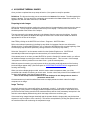
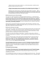
The fundamental concept of the modules is that each module may receive input from another module, and
may pass information to a successor module. This relation is shown by the left-to-right arrangement of the
selected modules in the status bar at the bottom of the main WinTES2 window illustrated below.
In this illustration, Module-A will send its data to Module-B. Whenever Module-B receives data from
Module-A, it will do whatever it is configured to do and then pass its data to Module-C. The icons
associated with each module are solely to aid in identifying them and neither imply nor serve any functional
purpose.
General Rules for Modules and their arrangement.
A particular module from the list of standard modules may appear zero or more times in the active
analysis configuration.
Data and control is moved from left to right in the order depicted in the status bar.
Modules may be configured to appear in any order, however some ordering patterns may be of no
useful value.
A module requiring user action will stop the flow of data and will remain the active module until the
user response requirement is met. Predecessor modules may continue to generate data and add
data sets to the input que of a module waiting for user action.
There is no mechanism for sending the output of one module to more than a single successor
module.
There is no mechanism for a module to receive data from more than one predecessor module.
There is no mechanism for sending the output of the last module back to the first module.
Modules will finish processing their current data before beginning the processing of the next set of
dat
a.I
ft
he“
Di
s
c
ar
dDat
a”opt
i
oni
ss
el
ec
t
ed,t
hemodul
ewi
l
l
begi
npr
oc
es
s
i
ngt
hemos
tr
ec
ent
(
newes
t
)dat
as
etandwi
l
l
di
s
c
ar
dal
l
ol
derdat
as
et
s
.I
f“
Di
s
c
ar
dDat
a”opt
i
oni
sNOTs
el
ec
t
ed,t
he
module will begin processing the oldest data set, and will keep newer data sets in its input que.
Receipt of data by a module acts as a trigger to activate the process implemented by that module
ev
eni
ft
hatmodul
edoes
n’
tac
t
ual
l
yus
eanyoft
hedat
ai
tr
ec
ei
v
es
.
Modules do not necessarily alter the data they receive, and many of them pass their input data
directly to their successor after performing their own process.
5. OPERATING SUGGESTIONS
Focusing
The 221 cameras utilize a manual focusing mechanism.
Many users find this process easier with the Grayscale colormap, since black and white images tend to
appear more natural. A technique, which gives excellent results, involves indirectly shining a 40 to 60 W
incandescent light on the unpowered target. To the 221 this is the functional equivalent of an infrared
flashbulb. The lamp illuminates the target and the camera displays the reflected IR energy. The resulting
image will look much like a visible light picture. Edges will be sharply defined, components will stand out
in sharp relief and fine focusing will be easier.
To use this technique, place the lamp about two feet above, and at an angle of about 45° to an
unpowered target. Don't shine the light directly into the aperture of the camera. Use Grayscale colormap
and take an image. You may have to experiment with the position of the lamp to get the best result.
When finished focusing, turn off the lamp as high levels of reflected infrared will distort the
temperature readings.
Framing or Determining What is Being Viewed
Framing involves two things: first, the aiming of the camera so the target is centered in the image;
second, being able to relate specific points in the thermal image to the corresponding locations on the
target. The same factors that make it more difficult to focus a thermal image can also make it harder to
frame properly. Many users find their first thermal images are ambiguous and confusing. But image
interpretation is quickly learned if the user has a working knowledge of the object being scanned.
Remember, it is important to have a well-focused image. Operating hint: Look for obvious reference
points. Typical hot spots are power resistors, power transistors, and power IC's. Cold or low emissivity
components would normally include mounting brackets, metal capacitors or crystal cans and bare copper
runs. Surface mount devices, hybrids, etc. are often framed by the contrasting colors of surrounding
heat sinks or substrates. Packaged IC's may be identified by the rows of legs or leads on the sides.
Edges of circuit boards are usually easy to find. In an energized board, conduction through the substrate
and ground plane normally creates some visible differential heating to the edge of the board. Providing a
good background can make the edges easier to see. A dark, matte finish material such as cardboard or
black paper behind the board can improve contrast.
Simple markers can be used as pointers. Any small non-conductive (for safety reasons) object at room
temperature will work. Plastic tools, non-metallic rulers are also useful. Put the marker on the target as
a pointer or an edge indicator, and then take an image. The marker should show up as a distinct dark
area against the warmer background of the board and its components. Objects you take out of your
pocket will already be warm and may not show up in the image. Some users have reported good success
with active (hot) markers. The wire will appear as a distinct hot pattern in the thermal image. The
focusing technique described above of using an incandescent lamp or other infrared source is also useful
for framing. Make a reflected IR image using that technique. Then, with the lamp off, make a normal
thermal image. Watch the display as the thermal image overlays the reflected IR image and you will see
which points correspond.Temperature Measurement
The Compix 221 is a sensitive instrument that has the capability to detect small temperature differences.
However, non-contact temperature measurements are affected by a number of variables that can change
the accuracy of temperature measurements. The following techniques will help improve the accuracy of
measurements made with the 221 system.
Be Consistent
Often all that is needed are good relative measurements. The engineer wants to know how one
temperature compares with another. Consistency is the key.
- Maintain the same environmental conditions, e.g., ambient temperatures, ventilation and the
presence of other heat sources in the room.
- Maintain the same physical set-up for the system. Put the boards in the same orientation -- flat
or upright, the same distance from the camera and the same relative position on the display.
-Maintain the same electrical set-up: same power inputs, same program to exercise it. While a
circuit board may take several minutes to reach thermal stability, it is not necessary to wait for the
board to stabilize, but comparative readings between boards will be more accurate if both circuits
are at approximately the same point in their warm-up cycles.
Minimize external sources of infrared energy.
The Compix 221 measures temperature by detecting emitted infrared energy, i.e. the infrared energy
generated by the target. Objects also reflect infrared energy from their surroundings.The 221 system (or
any other infrared system) can not tell the difference between reflected and emitted energy. Therefore,
reflected energy is a potential source of error. Some reflected infrared (IR) energy is unavoidable and the
221 will automatically compensate for typical levels of external IR energy, which are uniformly distributed
over the target. Nevertheless, it will be helpful to minimize significant sources of external IR, particularly
those that may not be uniformly distributed.
Other sources to avoid are direct sunlight coming through a window and shining on the target, or heat
from nearby electronic devices. A general rule of thumb is that if you can feel heat from a source near the
target, then it will affect the accuracy of the image.
Minimize the reflectivity of the target.
Another aspect of the problem described above is that some objects naturally reflect more infrared energy
than others do. Unfortunately, due to the laws of physics, good reflectors are poor emitters of infrared
(emissivity<<1.00). As a result, these objects produce a high ratio of reflected (undesirable) to radiate
(desirable) infrared, thus yielding less accurate temperature readings.
The solution is to reduce the reflectivity of these objects. Fortunately, surfaces that are reflective to
infrared are usually reflective to visible light. So look for bright, shiny or metallic surfaces, as they will be
the problem.
There are several easy ways to reduce reflectivity while minimally effecting the component's thermal
performance. A strip of electrical or masking tape on the top surface is one. Anything with a matte
surface is a good choice. Or a quick, light buffing with fine emery paper -- just enough to break the
surface sheen -- will also help. Most conformal coatings and solder masks provide a low reflectivity
surface for thermal images.Adjust the Emissivity setting
The default Emissivity setting of the 221 system is 1.00. This is appropriate for the highly emissive (low
reflectivity) materials that are most common on circuit boards. For components with lower emissivity,
temperature accuracy will be improved if the 221 system's emissivity setting is adjusted to match the
component's emissivity. Emissivity tables are available for many of the materials commonly used on
printed circuit boards.
Printing and exporting images
TES produces TIFF (Tag Image File Format) images that adhere strictly to the TIFF standard Revision
5.0 for Class-P (Palette Color) Images. Some software applications, which claim to be TIFF compatible
use a limited subset of the TIFF specification and may not import Compix TIFF files, so universal
compatibility is not assured.
The most reliable way to export a color image is to use the Copy command from the menu. This puts the
image into the clipboard from where it can be pasted into the appropriate document. Alternatively, Print
Screen may be used to copy a full Windows screen to the Clipboard or Alt Print Screen will copy only
the active window to the clipboard. These objects can usually be pasted into a Word, WordPerfect or
other word-processing document.
Additionally, the TIFF thermal image files may be opened in any of a number of applications programs.
Finally, images may be captured and saved using any of a number of commercially available screen
capture programs.
From these word processing or screen capture programs it is a simple matter to print to a file or printer.
6. MAINTENANCE
Calibration
It is recommended that instrument performance be verified once a year. The instrument should be
compared against a calibrated blackbody source. It is recommended the instrument be returned to the
factory for repair and recalibration.
Cleaning
Small amounts of dust or lint on the lens surface will have little or no effect on the performance or
calibration. It is possible to degrade the lens surface by improper or excessive cleaning techniques. Use
the following cleaning techniques carefully and not too frequently.
To remove loose dust or debris, use a gentle stream of dry air. Aerosol-type cans of clean dry air
available at camera and electronic stores are suitable for this purpose. For more persistent loose dust or
debris you may use a camelhair brush or soft cotton swab ("Q-tip"). Do not use lens tissues: Lens
tissues intended for eye glasses contain chemical additives and lens tissues available in camera
stores are often not soft enough.
Avoid touching the lens surface with your fingers. If you do need to clean off
fingerprints or other more resistant material, use clean alcohol or acetone to dampen a
soft cotton swab, gently dab, and swipe the spot or fingerprint. If you look at the lens
surface under magnification you will probably notice a few tiny defects in the coating
that have no measurable effect on the performance of the lens; But if you mistake such a
defect for debris and try to remove it you can make the defect larger.
Storage and transporting
The container in which the Compix 221 was originally shipped in should be used for storage or
transporting. If this is not possible, make sure adequate protection is provided to avoid damage while in
storage or during shipping. This can be accomplished by providing at least a two inch barrier of foam on
top, bottom, and all sides of the camera.
Repackaging for shipment
Ref
ert
o‘
Storage and transporting’
sect
i
onoft
heMai
nt
enancechapt
erf
ori
nst
r
uct
i
onsonr
eady
i
ngt
he
221 for shipment.
7. USER SUPPORT
User support is available by phone, mail, e-mail or in person at Compix' offices in Lake Oswego, Oregon.
Support will normally be available from 8:00 A.M. to 5:30 P.M. Pacific Coast Time, Monday through
Friday, excluding national holidays.
User support is generally free of charge on issues relating to interpretation of this manual, the proper
operation of the system, routine maintenance and warranty service. Consultation is generally not
available on image interpretation problems, fault diagnosis, system modifications or application specific
issues, particularly those outside the field of electronic test.
Compix reserves the right to determine, at its sole discretion, the extent of user support made available to
any user. A user may be asked to furnish proof of ownership of a Compix 221 system before receiving
support.
For support, contact Compix at www.compix.com/email1.htm, by phone at (503) 639-8496 or 1-800-6956257,
by FAX at (503) 639-1934,
or by mail at:
Compix Incorporated
Attn.: User Support/PC2000
P.O. Box 885
Tualatin, OR 97062-0885
When contacting Compix, identify yourself as a user of the Compix 221 system and ask for User
Support. It may be helpful for you to have the serial number of your 221 system and the version number
of TES you are using at the time of contact.
Visit http://www.compix.com/ for technical articles, price lists, product photos, and other information on
current products.If you want to visit us in person, please call us at the number above for directions and to
make sure the person best equipped to help you will be available when you arrive.
Our office location/ shipping address is:
Compix Incorporated
15824 SW Upper Boones Ferry Rd
Lake Oswego, OR 97035-4066
8. Compix 221 LIMITED WARRANTY
Compix warrants to the original buyer that this product shall be free of defects in materials and
workmanship and will meet its published specifications for a period of one year following the date of
shipment (the Warranty Period). Warranty service will be provided for this product if it is returned to
Compix Incorporated, shipment prepaid, during the warranty period. Compix will, at its option, either
repair or replace the product at no cost to the buyer, or refund the original purchase price of the product.
Limitations
This warranty shall not apply to defects resulting from accident, misuse, improper maintenance or
unauthorized modifications.
The remedies described above -- repair, replacement or refund -- are the buyer's sole and exclusive
remedies. Modifications or extensions of this warranty shall be effective only when made in writing,
signed by an officer of Compix Incorporated.
THIS WARRANTY IS EXPRESSLY IN LIEU OF ALL OTHER WARRANTIES, EXPRESS OR IMPLIED,
INCLUDING IMPLIED WARRANTIES OF MERCHANTABILITY AND FITNESS FOR A PARTICULAR
PURPOSE. COMPIX SHALL NOT BE LIABLE FOR ANY DIRECT, INDIRECT, SPECIAL, INCIDENTAL
OR CONSEQUENTIAL DAMAGES.
This warranty gives the buyer specific legal rights. The buyer may also have other rights
which vary from state to state.
Shipping
During the Warranty Period, Compix will reimburse the buyer for the buyer's reasonable shipping costs for
products returned to Compix from locations in the United States and Canada. Compix will also pay the
shipping charges to return the product to the buyer.
Before returning a product for service, contact Compix Customer Service for return authorization.
Compix Incorporated
15824 SW Upper Boones Ferry
Lake Oswego, Oregon 97035-4066
Voice (503) 639-8496
FAX: (503) 639-1934
E-mail: www.compix.com/email1.htm
APPENDIX A.
Accessories
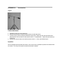
Tripod
Camera attachment
1. Spread the three legs of the tripod fully.
2. Move the tripod boom to allow for easy access to the ball and socket.
3. Loosen the joint (counter-clockwise) below the tripod neck. Rotate the neck with ball and socket
away from the boom to allow for easy access to the ¼ - 20 thread stem. Tighten the joint below the
tripod neck.
4. Connect the camera head to the ball and socket via the ¼ - 20 nut and threaded stem.
Operation
Use the thumbscrews at the ball and socket, neck, boom mount, leg holder to position the camera head
as needed. The body of the tripod can also be extended if needed.
Table top stand
Assembly
1. Attach the post to base using two bolts provided.
2. Attach the clamp assembly to the post.
Camera attachment
1. Attach the camera via the ¼ - 20 nut to the ¼ - 20 thumbscrew of the table top stand.
Operation
While holding the camera head with one hand, loosen the clamp assembly lock with the other, then rotate
the clamp assembly positioning handle to move the camera up or down. Tighten the clamp assembly
lock when camera is at desired location.
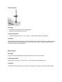
Medical tripod
Assembly
If tripod is not already assembled, attach head assembly to the base of the tripod.
Camera attachment
Attach the camera via the ¼ - 20 nut to the ¼ - 20 thumbscrew of the table top stand.
Operation
Thumbscrews at pivot points can be loosened, then tightened, to position the camera head as needed.
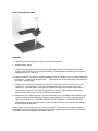
Heavy duty table top stand
Assembly
1. Attach the post to the base plate using the long-shaft socket driver.
2. Install the safety clamp
3. Install the camera support arm and pinion assembly onto the vertical shaft. Make sure the arm
support is oriented to the top of the pinion assembly. Gradually lower the assembly until the pinion
engages the rack. Do not force.
The optional positioner, if ordered, is shipped separately to prevent damage to the micrometer adjustment
mechanisms. To install it, follow steps 4-8.4.
Remove the four #6-32 socket-head cap screws from
their holes in the base plate.
5. Position the X-Y positioner over these four holes. The positioner may be mounted in any of four
orientations. The most common is to have one adjustment in front and the other to the right.
However, on a crowded bench, better protection against damage and accidental change may be
worth the inconvenience of mounting one adjustment to the back and the other to either side as
dictated by the environment or by the preference of the operator.
6. Install all four cap screws finger tight. It may be necessary to move the stage of the positioner to get
satisfactory access. Avoid manually moving the stage against the force of the return springs, and,
especially, DO NOT LET THE STAGE RETURN OUT OF CONTROL TO ITS REST POSITION.
(Repeatedly letting the stage slam against its stops under force of the return springs could damage
the micrometer mechanisms.)
Finally, tighten all four screws uniformly. Do not over tighten. Tighten them just enough to keep them
from vibrating loose or allowing the positioner to wiggle when operating the micrometers. Use a torque
screwdriver, if possible, and tighten the screws to 40 in-oz.
Camera attachment
1. Position the safety ring four inches (100mm) or more above the base. Tighten it securely in this
position. Later you will adjust the height of this ring so that the lens cannot possibly touch or crash into
the object being imaged.
2. Adjust the camera height by rotating the knurled knobs of the support arm and pinion assembly.3.
Re-position the safety ring so that the camera cannot come down too close to the object being
imaged. Tighten the safety ring. Always keep the safety ring positioned and tightened to insure that
the lens cannot fall onto, or come in contact with the object being imaged.
Operation
Set up the object to be imaged on a stable surface. (If the grid of #6-32 threaded holes of the optional XY positioner are used, be careful that the screws never engage beyond 0.2 inches (0.5mm) and protrude
through the stage. Nylon screws are recommended. Alternatively, a sample can often be installed
satisfactorily using masking tape or equivalent.)
Adjust the safety ring so that, with the lens cover in place, the camera cannot come down any further than
to have the lens cover almost touching the sample.
To raise or lower the camera, adjust the tension as needed, tight and slowly rotate the height adjustment
knob. The tension will automatically increase as you lower the camera, or decrease as you raise it. To
maintain constant tension, turn both knobs together.
Connect the camera cable, apply power, and proceed to operate in the normal manner (see chapter 3).
CAUTION: Never touch the lens or allow any object to touch or strike the lens.
Maintenance
Occasionally inspect all parts of the heavy duty stand, and X-Y positioner for damage and for
accumulation of dust and debris. Clean and lubricate (using a light oil) all moving parts as needed.
If it is necessary to ship the heavy duty stand, it is recommended that the X-Y positioner be removed and
packed separately. Make sure the support arm and safety clamp are tight, and use plenty of packing
material.
APPENDIX B.
Efficiency, Emissivity, Lens Factor, and Noise
Both emissivity and lens factor work alike to express the efficiency with which radiation from that object
reaches the sensor of the camera. Use what you already know about emissivity effects to understand
the effect of the Lens Factor.
The overall value for efficiency may be determined by multiplying the emissivity and lens factor. In the
following examples, the first three lines represent mathematically equivalent situations:
Emissivity
.49
1.00
.70
1.00
Lens Factor
1.00
.49
.70
1.00
Efficiency
.49
.49
.49
1.00
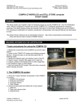
Background noise is exaggerated by non-unity lens factor or emissivity settings. To fully understand this
it may be helpful to view the top two lines of the Apparent Temperature table below. The first entry of
the second row simply indicates that for a 100% emissivity object, 30 oC would be reported; the second
entry indicates that a real surface of 0.9 (90%) emissivity would appear the same as a blackbody of only
29.1o C.
Another way of looking at the information contained in this table is to realize that if the emissivity were set
to 90%, then a black body of only 29.1o C would be converted to read out as 30o C. Similarly, the third
entry from the end in the first row indicates that a blackbody of only 22.9 o C would be converted to read
30o C if the emissivity setting were 20%.
Apparent Temperature of a 30oC Surface for various Emissivity %.
Emissivity
100
90
80
70
60
50
40
30
20
10
0
Apparent Surface Temperature
30
29.1
28.3
27.4
26.5
25.6
24.7
23.8
22.9
21.9
21.0
The background noise reported with a 100% efficiency setting (100 emissivity and 100 lens factor) will
typically span two to three degrees. Suppose a particular instrument reports background noise of 21o C
to 22.9o C. Suppose these values were converted with a lens factor of 20%. By definition, 21 o C is
converted to the same value, 21o C. But 22.9o C, as shown in the table fragment above, would be
reported as 30.0o C, resulting in a 9-degree span for the temperature-equivalent background noise.
Emissivities of common electronic materials
Material
Aluminum, polished
Aluminum, anodized
Gold, polished
Glass, smooth
Water (liquid state)
Black body
Plastic IC package
Ceramic IC Package
Silicon wafer
Simpson emissivity dots
Black electrical tape
Masking tape
Flat black paint
Emissivity (approximate)
.1-.25
.50-.60
.01-.04
.85-.95
.95-.97
1
.88-.95
.80-.85
IR Transparent
.95
.93-.95
.82-.85
.93-.95