1
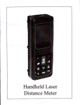
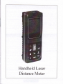
Handheld Laser
Distance Meter
User Manual
Symbols used
English
Congralulalions on the purchase of your
products.
Carefully read the Saf ety Instructions and the User
The symbols used in the Safety Instructions have the
following meanings:
AuRtrttc,
Indicates a potentially hazardous situstion
or an unintended use which, if not avoided,
will result in death or serious injury.
users
understand these directions and adhere to them.
A clurou,
Indicaes a potentially hazardous situation
or an unintended use which,if not avoided,
may result in minor injury and/or in appreciable material,financial and environmen-
tal damage.
lmportant paragraphs which must be
€
,
adhered to in practice as they enabled the
product to be used in a technically correct
and efficient manner.
Use of the instrument
Permitted use
Measuring distances
Computing functions,e.g.areas and volumes
Indirect measurement
Addition and subtraction operations of measurement
Prohibited use
. Using the instrument without instruction.
. UsinB outside the stated limits.
. Deactivation of safety systems and removal
of explanatory aad hazard labcts. Opening of the equipmeot by usi.ng tools
(screw drivers, etc.), as lar as not
specifically
permitted for certain cases.
. Carrying out modification or conversion of
the product.
. Use after misappropriation .
. Use of accessories from other
manufacturers
without the express approval of our
company.
. Deliberate or irresponsible behaviour on
scaffolding, when using ladders, when
measuring near machines which are
running, or near parts of machines or
installations which are unprotected.
. Aiming directiy into the sun
. Deliberate dazzling of third parties; also in
the dark
. Inadequate safeguards at the surveying site
(e.g.when measuring on roads, construction
sites, etc.)
Limits of use
See
section ttTechnical Data ".
The poduct is designed for use in areas perm
nently habitable by humans, do not use the product in
explosion hazardous areas or in
aggressive environments.
Areas of responsibi lity
As the original producer responsibility:
Responsible for providing security products
inciude manual and origin of the parts.
E
I
Responsibilities of the manufacturer of non-Original
accessories:
The manuf acturers of non- Original accessories
for the products are responsible for developing,
implementing and communicating safety concepts for
their products. They are also responsible for the
eff ectiviness of these safety concepts in combination
with the products equipment.
Responsibilities of the person in charge of the
instrument:
A weRrvrNc
The person responsible for the instrument
must ensure that the equipment is used in
person is also accountable for the deployment
of personnel and for their accordance with the
instructions. This training and for the safety
of the equipment when in use.The person in
charge of the instrument has the following duties:
. To understand the safety instructions on
the product and the instructions in the
User Manual.
. To be familiar with local safety regulations
relating to accident prevention.
. To inform Leica Geosystems immediately if
the equipment becomes unsafe.
Hazards in use
a cAutIoN'
Watch out for erroneous distance measurements if the instrument is defective or if it has been
dropped or has been misused or modified.
Precautions:
Carry out periodic test measurements. Parti-
H
't
I
cularly after the instrument has been subject
to abnormal use, and before, during and aiter
important measurements.
Make sure the optics is kept clean and that there
is no mechanical damage to the bumpers.
A
cAuttol:
In using the instrument for distance measure_
ments or for positioning moving objects (e.g.
cranes, building equipment, platforms, etc.)
unforeseen events may cause erroneous mea_
surements.
Precautions:
Only use this product as a measuring sensor,
not as a control device. your system must be
configured and operated in such a way, that in
case of an erroneous measurement, malfunction of the
device or power failure due to installed safety measures
(e.g. safety limit switch), it is assured that no damage
will occur.
A wARwrNc:
Flat batteries must not be disposed of with
household waste. Care for the environment
Always prevent access to the product by unauthorized.
Dersonnel.
and take them to the collection points
\ffij
lXl provided in accordance with national
or local provided in accordance with
lA
' u v \ national or local regulations.The
product must not be disposed of wit household
waste.Dispose of the product appropriately in
accordance with the national regulations in force in
your country.
Electromagnetic Compatibility ( EMC)
I
I
The term "electromagnetic compatibility" is taken to
mean the capability of the product to function
I
smoothly in an environment where electromagnetic
radiation and electrostatic discharges are present, and
without causing electromagnetic interference to other
equipment.
AwARwItto:
The products conforms to the most stringent
requirements of the relevant standards and
regulations. Yet, the possibility of it causing
interference in other devices cannot be totally
excluded.
acrutroN:
Never attempt to repair the product yourself .
In case of damage, contact the local dealership.
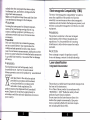
Laser classification
lntegrated distancemeter
d
)
The produces a visible laser beam which emerges from
the front of the instrument.
It is a CIass 2 laser product in accordance with:
. IEC60825- I : 2OO7 "Radiation saf ety of laser
products"Laser Class 2 products:
Do not stare into the laser beam or direct it to
wards other people unnecessarily. Eye protection is normally alforded by aversion responses including the blink reflex.
a
AwenNII.tc,
c Insert batteries, observing correct
Looking directly into the beam with optical aids
binoculars, telescopes) can be hazardous.
3 Close
Replace the batteries when the symbol
flashes permanently in the display.
Precautlons:
Do not look directly into the beam with optical aids.
AcAurtorv,
Looking into the laser beam may be hazardous to the
eyes.
Precautions:
Do not look into the laser beam. Make sure the laser is
aimed above or below eye level. (particularly with fixed
polarity.
the battery compartment again.
6 only
I
use alkaline or rechargeable
batteries.
6
R.rnou. the batteries before any long
period of non-use to avoid the danger of
corrosion.
installations, in machines, etc.)
Labelling
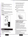
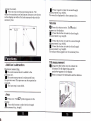
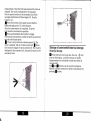
Ghanging the reference point
(mu ltifunctional endpiece)
The instrument can be adapted for the following
measuring situations:
. For measurements from an edge, fold out the
positioning bracket until it first locks in place.
. For measurements from a corner, open the
positioning bracket until it locks in place, then push
the positioning bracket lightly to the right to fold it out
lnserting/replacing batteries
1 Remove battery compartment lid and attach
handstrap.
fu1ly.
A built-in sensor automatically detects the orientation
of the positioning bracket and adjusts t1ne zero point of
the instrument accordingly.
. For measurements from an edge, fold out the
positioning bracket until it first locks in place.
. For measurements from a corner, open the
lmsitioning bracket until it locks in p1ace, then push
positioning bracket
Ite oositioning
hrqcket lightty
liohfl,, to
+^ the
+r.i right
+^ foli
i^ta it
:. out
-;^ri to
^
. A built-in sensor automatically detects the
rtation of the positioning bracket and adjusts the
point of the instrument accordingly.
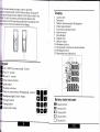
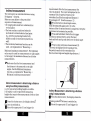
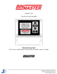
Display
2
Laser active
Reference
3
Indirect measurement (Pythagoras)
4
Delay measurement
Area volume measurement
Stored record
Data display
1
5
6
7
8 Display unit
9 Battery status
10 Hardware failure
11 The dynamic continuous
12 Marking Iunction
measurement
t3 Operation error indication
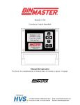
ad
/ DIST (On/measuring) - button
Plus (+) - button
Minus (-) - button
Area/ volum e- button
Angle button
ON
Referenc e-button
Indirect measurement (pythagoras) - button
Background light/ Units-button
Storage-button
-flflfl
frflt;n
Battery state indicator
Timing button
.TiiI) g211s1ylOOoh
Clearn/ off-button
XE eatteryTs%
.Ti-) Battery50%
T-a Battery21oh
I
Batteryo%
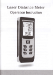
Standard supply part
Laser Distance Meter
can be shown on the display.
i nating display (,tfl]
ffi brtto., (press short), the illuminating display
1 portable belt
ll I um
1 operating instructions
1 protective bag
1 warranty card
be turned on or off.
2 battery
can
The Correctaon of tilt sensor
@ to enter into the "Tilt sensor"
mode. Conti.ruouslfp.ess this button Qf five times
Press this button
Measurements
.@ brltto-n-(p.essed long) - press once again to change
the unit of distance measurement.
The following units are available: m (meter), ft (f eet), in
(inch), 11 + / in (f eet - inch 1/ 16).
Beep
J button
a;
(press long). you can choose the beep on or
off as required.
Laser Continuous (-x)
! eress and hold downihe liey when switching on the
d&ice until the character t .pp".r" permanently in the
display with beep sounds. Every further press oi tne
!
key releases a distancerneasurement.
@ p.es" the kE
and hold to switch the device and laser-continuous
operation off.
Measuring with tripod
The reference must be appropriately adjusted in order
to be able to take correct measurements with a tripod.
You can switch the referenc. by |@ button. The setting
again when the bottom of display shows 0.0; Then press
l,;l':J"Lo""H:'.U;;.'if.i'""3,'ff;Hff
';l;i?'*#
thebu.ttol !
and it shows O.2;wait several
^once
seconds till it shows 0.0
for finishing the correction.
Press
Press this button
@ to. exiting.
Switching on and off
Switches on the instrument and laser. The
disnlay shows the battery symbol until the
I next button is pressed.
. @ Pressing_this button for longer switches the
instrument off .The instrument switches off
automatically after three minutes of inactivity.
Clear button
@ fne last action is cancelled. While making
area or volume measurements, each single
measurement can be deleted and remeasured
in series.
Refenece setting
The default reference setting is from the rear of the
'
H'tsT*1';ff""#:i"':: J*::t l,Y#l;.
w
i
extended along as the reference edge. The
L
@ Press button to activate horizontal measurement in
the instrument. The following symbol
be
@ P.... this button, will measure
the reference edge
fixed to the forefront. The display will show youEl-.
l@ P.."" this button, the rear reference is set
again.
t
I
Level
Timer (self-triggerin g)
@ Press this button to set a S-second time delay. or@
You can choose the level gauge on or off as
required by press this butto; (A)
i'l?:
3"
?i
::1i;:,n?r:i
$:*
Press and hold down this button until the desired time
delay is reached (max. 30 seconds).Once the key is
released the remaining seconds until measurement
(e.g.29,28,27...1 are displayed in a countdown. The
last 5 seconds are counted down with a beep. After the
last beep the measurement is taken and the value is
asain,.
trigger the distance measuremeiT. The result
is displayed immediately.
displayed.
(F=fn. timer
tilt sensor measures tilts between
+ 45"
G=nuring the measurement of tilt, the
instrument should be held without
transverse tilt, as far as possible, ( +
10" ).
Horizontal measurement
can be used for all
measurements.
Tilt measurement
fffn.
displayX .lf the button is active, the
horizontal distance is displayed in the summary line for
each distance measurement (up to max. + / -45" and up
tqnax. a transverse 1i11 e1 +/-tO' ).
! Press the button to collect the measurement data,
and the data will be on the display. And the height
distance, horizontal distance, hypotenuse distance and
angle will be showed on auxiliary display in turn.
appears in the
disptay will show youF-.
I
i
?,
Minimum/maximum measurement
This function allows the user to measure the
minimum or maximum distance from a fixed
measuring point. It can also be used as to
determine spacings.It is commonly used to measure
room diagonals (maximum values) or horizontal
distances (minimum values).
and hold down this button until you hear a
- ! ry9ss
beep. 'l'hen slowly sweep the laser back and forth and
up and down over the desired target point(e.g. into the
corner of a room).
P.es" to stop continuous measurement. The
values for maximum and minimum distances are shown
in the display as well as the last measured value in the
!
!
m-ea
eress it again to take the second length
surem ent
(e.
g. wi dth).
The result is displayed in the summary line.
summary line.
mtn
l-
Volume
Ql P.."" this button twice. Thel@symbol
appears in the display.
! Press this button to take the first length
mtasurement (e. g. length).
I Press this button to take the second length
measurement (e.g. width).
I Press this bJtton to take the third length
measurement (e. g. height).
The volume then appears in the summary line.
m
Tilt measurement
Addition / subtraction
6
Distance measurins.
! rar. next measurement ,s added to the
orevious
one.
'J ffr. next
measurement is subtracted from
the previous one.This process can be repeated as
reouired.
!
tf,.last step is cancelled.
Area
El P..""
otce. ThJ/Esymbol appears in the
display.
!
m-eas
Press this button to take the
(e. g. I en gth).
urement
first length
Long press this button once to activate the
sensor.The tilt degree data and tilt
sl,rnbollorlappears irr the display.
tilt
_
! e.."" to measure the inclination
and the distance
Indirect measurement
The instrument can calculate distances using
Pythagoras' theorem.
Make sure you adhere to the prescribed
sequence of measurement:
.
I target points must be in a horizontal or
vertical plane.
. The best results are achieved when the
instrument is rotated about a fixed point
(e.g. with the positioning bracket fully
folded out and the instrument placed on a
wall).
. The minimum/maximum function can be
used - see explanation in "Measuring ->
Minimum/maximum measurement". The minimum
value must be used for measurements at r ight angles
to the target; the maximum distance for all other
measurements.
A1
measurement.After the first measurement the
value is adopted. The result is displayed in the
summary line,the partial results in the
secondary line.(Such as:angle and distance.)
If bevelangle>45' ,Need to measure (2)
@ Press this butron,closed angle sensor,
Shall be measured again point ( 1) in the
distance.After the measurement is completed, Keep the
i4trument
as horizontal as possible.
! eress and hold down this button to trigger
continuous
measurement, sweep the laser
back and forth and up and down over the ideal target
f"J;.""
to stop continuous measurement (2).
The result is displayed in the summary line,
the partial results in the secondary line.
(Such as:bevel edge and angled edge distance.)
(FMake sure that the first measurement and
the distance to be measured are at right
angles. Use the Minimum/maximum
function, as explained in "Measuring ->
Minimum/ maximum measurement".
indirect measurement - determining a distance
using 2 auxilliary measurements
e.g. for measuring building heights or widths.
It is helplul to use a tripod when measuring
heights that require the measurement of two or three
measurements.
lndirect Measurement - determining a distance
using 3 measurements
@ Press this button twice; the display shows the
@ Press this button once, the display =ho*"41.
The laser is switched on.
following symbol(.The laser is switched on.
! ,lrrn ar rne upper pornr ( r, and trrgger the
! eim at the upper point (1) and trigger
the
measurement. After the first measurement the value is
adopted. The result is displayed in the summary
line,the partial results in the secondary line.(Such
as:angle and distance.)If bevel angle>45" ,Need to
measure (2)
@ Press this button,closed angle sensor,Shall be
measured again point ( 1) in the distance.
After the measurement is completed, Keep the
iqgtrument as horizontal as possible.
! e.."" and hold down thiibutton to trigger
continuous measurement, sweep the laser up and down
over the ideal tareet ooint.
! P.""" to stop"continuous measurement (21- The
vElue is adopted. Aim at the lower point and ! Pr""=
this button to trigger the measurement (3). ThEresult is
displayed in the summary line, the partial results in the
secondary lines.
Storage of constants/historical storage
Historical storage
@ Pr."" this button for long time, the icon (S) will
show on the display , and the previous 10 results
(measurements or calculated results) are shown in
reverse order.
The!andjbuttons can be used for navigation.
Make it available constant for further calculations by
pressing @ button.
IiI!I
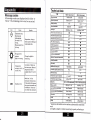
Technical data
ITEM
Message codes
1
00m instrument
g range
message codes are displayed with either or
"Error". The following errors can be corrected:
A11
rg accuracy
+
.aser type
Remedy
rrsEnce measuremsntwith
Calculation error,
Rrceiving t}Ie
reflected light
too weak or too
strong,
Measurment time
Reoperation, chmge a
better surface refl@ting or
using teget plate.
tiI
1mm
Class 2[4 ll
620-690nm< 1mW
620-690nms 1mW
o
sensot
*
! 45'
t
45"
lonzonhl measurement accuracy
r 0.3'
i
0.3'
o
a
a
o
a
a
a
Errecr measuremenl
,ythagoEs proposilion
fl
(a)
['emperature
oo high ( +40t ) or
oolow(OC)
lhmge the light for
neasuring..
lisplay illumination
ihow b@p
lool dom or Wm up
:he instrument, Extemal
i4ultifu
lemperature will be
rvailable Irom OC to +4o
nctional end piece
rctection against splashes and dr
{istori€l storage
2800
Hardwae error
.aser switch-off automati€llV
Automati€lly
Automati€lly
tP 54
IP 54
t0
0C to +4OC
-20t
LR6(AA)2x15V
Afrer 30 seconds
switch{ff automati@lly
18 x49
LR6 (AA) 2
1.5v
Aner 3 minutes
:27 mm
without battery
r
After 30 se@nds
118 x49 x27 mm
1509
(
to +7(rc
5000 to 8000 measurement
Afrer 3 minutes
1
Veight
*
a
a
-20C to +7m
)imensions
rueight
O
5000 to 8000 measurement
,atrery setection
nstrument
a
0C to +4OC
ompeEture range for Storage
,atery life
a
a
a
a
o
10
re Enge for Operation
Switch on / off the
instrument sevqal times.
If the symbol still appears,
then your instMent may
be defecdve. Please call
your dealer Ior assistance.
a
ronzon@t measurementrange
1US-mlnus method
lhe goal of the
rmbient
ight is too strong
'
lmm
\rea, Volume measuring
loo long
0.05 to 80 M
Typi@lt2mm'"
Class 2t4 ll
.aser classm@tion
Cause
80m instrumenl
Typicalr2mmt.
Jrsplay accuEcy
lcon
.
0.05 to 100 M
1
)
(
509
without battery
)
maximum deviation occurs under unfavourable conditions
such
as bright sunlight or when measuring to poorly reflecting or
very rough surfaces. Measuring accuracy between 1O m and 3O m
may deteriorate to approx. + 0.025 mm/m, for distances above 30 m
to + 0.1 mm/m.
Measuring conditions
Measuring range
The range of l00m instrument is limited to 100m.The
range of 80m instrument is limited to 80m.
At night or dusk and if the target is in shadow
the measuring range without target plate is
increased. Use a target plate to increase the
measurement range during daylight or if the
target has poor reflection properties.
Target surfaces
Measuring errors can occur when measuring
toward colourless liquids (e.g. water) or dust
free glass, Styrofoam or similar semiperme-able
surfaces. Aiming at high gloss surfaces may deflect the
laser beam and lead to measurement errors.Against
non-reflective and dark surfaces the measuring time
may increase.
Care
Do not immerse the instrument in water. Wipe
ofl dirt with a damp, soft cloth. Do not use
aggressive cleaning agents or solutions. Handle the
insttument as you would a telescope or camera.
Warranty
The instrument comes with a one-year warranty.
This warranty effective premise is: according to the
company's operating instructions for correct operation,
processing,cleaning and maintenance of the tool, and
aq
the tool is maintained good technical condition.This
means that in the tool can be used in the company's
original components and spare
parts.This warranty is provided in the tool during the
whole life expectancy of the defective parts of the
repaired or replaced free of charge.If the component due
to normal wear and in need of repair or replacement, is
not in the warranty van.
illustrations, descriptions and technical
specifications may be subject to change without prior
notice.
A11
Serial
nmber:_
_
Product t)?e:
Nme
Iiser
prchGe:
Product nme:
Date of
distance meter
of pmhaser:
Address:
_
Distribution nme:
Zip code:
Dealer seal:
.The whole of laser distmce meter.
Battery, targot board, hmd strap, soft package, packaging md other auxiliary
equipmmts are not in the free mintenm@ rage.
rtffiffiffiffi
Not registered of puchasing date on the warrmty caid, the free
maintenance setrice of this machine will be from the date of mufacture.