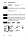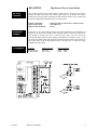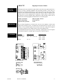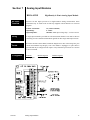
1
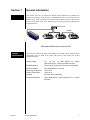
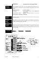
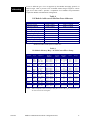
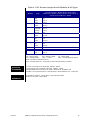
Instruction Manual
CI-ControlWave
Wave RI/O
Issue: 08/2001
TM
Ethernet Distributed (Remote) I/O MODULES
Discrete I/O Modules:
BB-8DI2-8DO2-H, BB-16DI2-H & BB-8CNT
Discrete Output Modules:
BB-16DO2-H
Discrete / Analog Modules: BB-8DI2-8AI2-H & BB-4RTD-4DI2-U
Analog Input Modules:
BB-16AI2-H & BB-8INS-U
Analog I/O Modules:
BB-8AI2-4AO2-H
ControlWave
ControlWave
Ethernet I/O
Bristol Babcock
NOTICE
Copyright Notice
The information in this document is subject to change without notice. Every effort has been
made to supply complete and accurate information. However, Bristol Babcock assumes no
responsibility for any errors that may appear in this document.
Request for Additional Instructions
Additional copies of instruction manuals may be ordered from the address below per
attention of the Sales Order Processing Department. List the instruction book numbers or
give complete model number, serial or software version number. Furnish a return address
that includes the name of the person who will receive the material. Billing for extra copies
will be according to current pricing schedules.
ControlWaveTM is a trademark of Bristol Babcock. Other trademarks or copy-righted
products mentioned in this document are for information only, and belong to their respective
companies, or trademark holders.
Copyright (c) 2001 Bristol Babcock, 1100 Buckingham St., Watertown, CT 06795. No part of
this manual may be reproduced in any form without the express written permission of
Bristol Babcock.
IMPORTANT! READ INSTRUCTIONS BEFORE STARTING!
Be sure that these instructions are carefully read and understood before any
operation is attempted. Improper use of this device in some applications may result
in damage or injury. The user is urged to keep this book filed in a convenient
location for future reference.
These instructions may not cover all details or variations in equipment or cover
every possible situation to be met in connection with installation, operation or
maintenance. Should problems arise that are not covered sufficiently in the text, the
purchaser is advised to contact Bristol Babcock for further information.
EQUIPMENT APPLICATION WARNING
The customer should note that a failure of this instrument or system, for
whatever reason, may leave an operating process without protection. Depending
upon the application, this could result in possible damage to property or injury to
persons. It is suggested that the purchaser review the need for additional backup
equipment or provide alternate means of protection such as alarm devices, output
limiting, fail-safe valves, relief valves, emergency shutoffs, emergency switches, etc.
If additional information is required, the purchaser is advised to contact Bristol
Babcock.
RETURNED EQUIPMENT WARNING
When returning any equipment to Bristol Babcock for repairs or evaluation,
please note the following: The party sending such materials is responsible to ensure
that the materials returned to Bristol Babcock are clean to safe levels, as such levels
are defined and/or determined by applicable federal, state and/or local law
regulations or codes. Such party agrees to indemnify Bristol Babcock and save
Bristol Babcock harmless from any liability or damage which Bristol Babcock may
incur or suffer due to such party's failure to so act.
ELECTRICAL GROUNDING
Metal enclosures and exposed metal parts of electrical instruments must be
grounded in accordance with OSHA rules and regulations pertaining to "Design
Safety Standards for Electrical Systems," 29 CFR, Part 1910, Subpart S, dated: April
16, 1981 (OSHA rulings are in agreement with the National Electrical Code).
The grounding requirement is also applicable to mechanical or pneumatic
instruments that include electrically-operated devices such as lights, switches, relays,
alarms, or chart drives.
EQUIPMENT DAMAGE FROM ELECTROSTATIC DISCHARGE VOLTAGE
This product contains sensitive electronic components that can be damaged by
exposure to an electrostatic discharge (ESD) voltage. Depending on the magnitude
and duration of the ESD, this can result in erratic operation or complete failure of the
equipment.
Bristol Babcock 1100 Buckingham Street, Watertown, CT 06795
Telephone (860) 945-2200
WARRANTY
A.
Bristol warrants that goods described herein and manufactured by Bristol are free
from defects in material and workmanship for one year from the date of shipment
unless otherwise agreed to by Bristol in writing.
B.
Bristol warrants that goods repaired by it pursuant to the warranty are free from
defects in material and workmanship for a period to the end of the original warranty
or ninety (90) days from the date of delivery of repaired goods, whichever is longer.
C.
Warranties on goods sold by, but not manufactured by Bristol are expressly limited
to the terms of the warranties given by the manufacturer of such goods.
D.
All warranties are terminated in the event that the goods or systems or any part
thereof are (i) misused, abused or otherwise damaged, (ii) repaired, altered or
modified without Bristol's consent, (iii) not installed, maintained and operated in
strict compliance with instructions furnished by Bristol, or (iv) worn, injured or
damaged from abnormal or abusive use in service time.
E.
THESE WARRANTIES ARE EXPRESSLY IN LIEU OF ALL OTHER WARRANTIES EXPRESS OR IMPLIED (INCLUDING WITHOUT LIMITATION WARRANTIES AS TO MERCHANTABILITY AND FITNESS FOR A PARTICULAR
PURPOSE), AND NO WARRANTIES, EXPRESS OR IMPLIED, NOR ANY REPRESENTATIONS, PROMISES, OR STATEMENTS HAVE BEEN MADE BY BRISTOL UNLESS ENDORSED HEREIN IN WRITING. FURTHER, THERE ARE NO
WARRANTIES WHICH EXTEND BEYOND THE DESCRIPTION OF THE FACE
HEREOF.
F.
No agent of Bristol is authorized to assume any liability for it or to make any written
or oral warranties beyond those set forth herein.
REMEDIES
A.
Buyer's sole remedy for breach of any warranty is limited exclusively to repair or
replacement without cost to Buyer of any goods or parts found by Seller to be
defective if Buyer notifies Bristol in writing of the alleged defect within ten (10) days
of discovery of the alleged defect and within the warranty period stated above, and if
the Buyer returns such goods to Bristol's Watertown office, unless Bristol's Watertown office designates a different location, transportation prepaid, within thirty (30)
days of the sending of such notification and which upon examination by Bristol
proves to be defective in material and workmanship. Bristol is not responsible for
any costs of removal, dismantling or reinstallation of allegedly defective or defective
goods. If a Buyer does not wish to ship the product back to Bristol, the Buyer can arrange to have a Bristol service person come to the site. The Service person's
transportation time and expenses will be for the account of the Buyer. However,
labor for warranty work during normal working hours is not chargeable.
B.
Under no circumstances will Bristol be liable for incidental or consequential damages
resulting from breach of any agreement relating to items included in this quotation
from use of the information herein or from the purchase or use by Buyer, its
employees or other parties of goods sold under said agreement.
How to return material for Repair or Exchange
Before a product can be returned to Bristol Babcock for repair, upgrade, exchange, or to
verify proper operation, form (GBU 13.01) must be completed in order to obtain a RA
(Return Authorization) number and thus ensure an optimal lead time. Completing the form
is very important since the information permits the Bristol Babcock Repair Dept. to
effectively and efficiently process the repair order.
You can easily obtain a RA number by:
A. FAX
Completing the form (GBU 13.01) and faxing it to (860) 945-3875. A BBI Repair
Dept. representative will return call (or other requested method) with a RA number.
B. E-MAIL
Accessing the form (GBU 13.01) via the Bristol Babcock Web site
(www.bristolbabcock.com) and sending it via E-Mail to [email protected].
A BBI Repair Dept. representative will return E-Mail (or other requested method)
with a RA number.
C. Mail
Mail the form (GBU 13.01) to
Bristol Babcock Inc.
Repair Dept.
1100 Buckingham Street
Watertown, CT 06795
A BBI Repair Dept. representative will return call (or other requested method) with
a RA number.
D. Phone
Calling the BBI Repair Department at (860) 945-2442. A BBI Repair Department
representative will record a RA number on the form and complete Part I, then send
the form to the Customer via fax (or other requested method) for Customer
completion of Parts II & III.
A copy of the completed Repair Authorization Form with issued RA number should be included with the product being returned. This will allow us to quickly track, repair, and
return your product to you.
Bristol Babcock Inc. Repair Authorization Form
(Providing this information will permit BBI to effectively and efficiently process your return. Completion is required to
receive optimal lead time. Lack of information may result in increased lead times.)
Date___________________
RA #___________________SH_
Standard Repair Practice is as follows: Variations to this is
practice may be requested in the “Special Requests” section.
• Evaluate / Test / Verify Discrepancy
• Repair / Replace / etc. in accordance with this form
• Return to Customer
Part I
Line No.____________
Please be aware of the Non warranty standard charge:
• There is a $100 minimum evaluation charge, which is
applied to the repair if applicable (√ in “returned” B,C,
or D of part III below)
Please complete the following information for single unit or multiple unit returns
Address No.
(office use only) Address No.
(office use only)
Bill to :
Ship to:
Purchase Order:
Contact Name:____________________________________
Phone:
Fax:
Part II
E-Mail:
Please complete Parts II & III for each unit returned
Model No./Part No.
Description
Range/Calibration
S/N
Reason for return :
1.
Failure
Upgrade
Verify Operation
Other
Describe the conditions of the failure (Frequency/Intermittent, Physical Damage, Environmental Conditions,
Communication, CPU watchdog, etc.)
(Attach a separate sheet if necessary)
2.
Comm. interface used:
3.
What is the Firmware revision? _____________________
Standalone
RS-485
Ethernet
Other:______________
Modem (PLM (2W or 4W) or SNW)
What is the Software &version?
Part III If checking “replaced” for any question below, check an alternate option if replacement is not available
A. If product is within the warranty time period but is excluded due
to BBI’s warranty clause, would you like the product:
repaired
returned
replaced
scrapped?
B. If product were found to exceed the warranty period,
would you like the product:
repaired
returned
replaced
scrapped?
C. If product is deemed not repairable would you like your product:
returned
replaced
scrapped?
D. If BBI is unable to verify the discrepancy, would you like the product:
returned
replaced
*see below?
* Continue investigating by contacting the customer to learn more about the problem experienced? The person to contact that
has the most knowledge of the problem is:
_______________________________ phone
If we are unable to contact this person the backup person is: _________________________ phone
Special Requests:
Ship prepaid to: Bristol Babcock Inc., Repair Dept., 1100 Buckingham Street, Watertown, CT 06795
Phone: 860-945-2442
Fax: 860-945-3875
Form GBU 13.01
Rev. A
Bristol Babcock
Training
GET THE MOST FROM YOUR BRISTOL
BABCOCK INSTRUMENT OR SYSTEM
● Avoid Delays and problems in getting your system on-line
● Minimize installation, start-up and maintenance costs.
● Make the most effective use of our hardware and software.
● Know your system.
As you know, a well-trained staff is essential to your operation. Bristol Babcock offers a full
schedule of classes conducted by full-time, professional instructors. Classes are offered
throughout the year at four locations: Houston, Birmingham, Orlando and our Watertown,
CT headquarters. By participating in our training, your personnel can learn how to install,
calibrate, configure, program and maintain any and all Bristol Babcock products and realize
the full potential of your system.
For information or to enroll in any class, contact our training department in Watertown at
(860) 945-2269. For Houston classes, you can also contact our Houston office, at (713) 6856200.
BLANK PAGE
A Few Words About Bristol Babcock
For over 100 years, Bristol7 has been providing innovative solutions for the measurement
and control industry. Our product lines range from simple analog chart recorders, to
sophisticated digital remote process controllers and flow computers, all the way to turnkey
SCADA systems. Over the years, we have become a leading supplier to the electronic gas
measurement, water purification, and wastewater treatment industries.
On off-shore oil platforms, on natural gas pipelines, and maybe even at your local water
company, there are Bristol Babcock instruments, controllers, and systems running year-in
and year-out to provide accurate and timely data to our customers.
Getting Additional Information
In addition to the information contained in this manual, you may receive additional assistance in using this product from the following sources:
Contacting Bristol Babcock Directly
Bristol Babcock's world headquarters are located at 1100 Buckingham Street, Watertown,
Connecticut 06795, U.S.A.
Our main phone numbers are:
(860) 945-2200
(860) 945-2213 (FAX)
Regular office hours are Monday through Friday, 8:00AM to 4:30PM Eastern Time,
excluding holidays and scheduled factory shutdowns. During other hours, callers may leave
messages using Bristol's voice mail system.
Telephone Support - Technical Questions
During regular business hours, Bristol Babcock's Application Support Group can provide
telephone support for your technical questions.
For technical questions about TeleFlowÔ products call (860) 945-8604.
For technical questions about ControlWave call (860) 945-2244 or (860) 945-2286.
For technical questions regarding Bristol’s OpenEnterprise product, call (860) 945-2501 or
e-mail: [email protected]
For technical questions regarding ACCOL products, Open BSI Utilities, as well as
Bristol's Enterprise Server7/Enterprise Workstation7 products, call (860) 945-2286.
For technical questions about Network 3000 hardware, call (860) 945-2502.
You can e-mail the Application Support Group at: [email protected]
The Application Support Group also maintains a service area within our main web site.
Technical information, as well as software updates are available in this area. To access our
web site, go to: bristolbabcock.com/services/techsupport/
For assistance in interfacing Bristol Babcock hardware to radios, contact Communication
Technologies in Orlando, FL at (407) 629-9463 or (407) 629-9464.
Telephone Support - Non-Technical Questions, Product Orders, etc.
Questions of a non-technical nature (product orders, literature requests, price and delivery
information, etc.) should be directed to the nearest sales office (listed below) or to your
Bristol-authorized sales representative.
Major U.S. Sales Offices
Major International Sales Offices:
Watertown, CT (860) 945-2262
Birmingham, AL (205) 980-2010
Ontario, CA (909) 923-8488
Farmington, NM (505) 327-3271
Houston, TX (713) 685-6200
Richardson, TX (972) 238-8935
Bristol Babcock Ltd (UK): (441) 562-820-001
Bristol of Canada: (416) 675-3820
Bristol Babcock Asia Pacific 61 8-9455-9955
BBI, S.A. de C.V. (Mexico) (525) 254-2131
Please call the main Bristol Babcock number (860-945-2200) if you are unsure which office
covers your particular area.
Visit our Site on the World Wide Web
For general information about Bristol Babcock and its products, please visit our site on the
World Wide Web at: www.bristolbabcock.com
Instruction Manual
ControlWave
Ethernet Distributed
(Remote) I/O Modules
ControlWave
Ethernet I/O
Contents at a Glance:
Section 1
General Information
Ethernet I/O modules
2
Section 2
Ethernet and RS485 Wiring
Remote I/O, Ethernet I/O Expansion
3
Section 3
Configuration Tools
BB-232-SETUP and Windows Tools
4
Section 4
Discrete I/O Modules
BB-8DI2-8DO2-H, BB-16DI2-H, BB-8CNT
7
Section 5
Discrete Output Module
BB-16DO2-H
10
Section 6
Discrete / Analog Modules
BB-8DI2-8AI2-H, BB-4RTD-4DI2-U
11
Section 7
Analog Input Modules
BB-16AI2-H, BB-8INS-U
13
Section 8
Analog I/O Module
BB-8AI2-4AO2-H
15
Section 9
Modbus Communications
Scheme Configuration Notes
16
Supplements & Appendices
Special Instructions for Class I, Division 2 Hazardous Locations ......................... Appendix A
Class I, Division 2,
Groups A, B, C, and D
Hazardous Locations
CI-ControlWaveRI/O
Table Of Contents
1
Section 1
General Information
Overview
This manual will help you install and maintain Ethernet Remote I/O Modules and
gateways. In summary, wiring for power, communications and I/O is connected to each
module’s base. Then, setup choices are entered using the Remote I/O Tool Kit software
and the system will be ready to run. Shown below are some typical system configurations
using Ethernet I/O:
Ethernet Hub
RS 485
ControlWave
Ethernet I/O
ControlWave
Ethernet I/O
ControlWave
Ethernet I/O
Distributed Ethernet and serial I/O
General
Specifications
These general specifications apply to all Ethernet I/O modules. More detailed product
specifications may be found in the online help system of the Remote I/O Toolkit
configuration utility.
Supply Voltage
Section 1
RS485 Expansion
10 - 30 Vdc, 1.2 Watt typical per module
(48 mA @ 24 Vdc - varies by module and load).
Connect up to 32 Remote I/O modules using RS485
Ethernet Isolation
Operating Temperature
Storage Temperature
Humidity
1200 Volts RMS (for 1 minute)
-30 to 70 °C
-40 to 85 °C
5 to 95% (non-condensing)
Protocols Supported
Open Modbus/TCP, Serial Modbus RTU & ASCII
Universal
General Information
2
Section 2
Ethernet and RS485 Wiring
DC Power
Overview
Ethernet I/O modules can be powered from the same DC source that is used to power
your I/O devices. No separate power supply is required. Typically, 10 to 30 VDC power
is applied to terminals 24 and 25 on the base of each module. Refer to the upcoming
wiring diagram for each module for power connections.
RS485 Wiring
Guidelines
The RS485 party-line consists of two wires and an isolated ground wire. It is
recommended that the ground wire be connected to all stations to provide a common
return. The RS485 port on all Ethernet I/O modules is isolated from its internal circuitry,
local power source, and I/O wiring to improve communications reliability. It is
recommended that only 32 Remote I/O modules be connected on any RS485 party-line,
and that the termination jumper be installed on the last module on each end of the RS485
network. Limiting the cabling to two network arms (segments) radiating from the master
controller will yield the best signal results.
Screw Torque
Section 2
19 20 21 22 23
G + - T1 T2
19 20 21 22 23
G + - T1 T2
19 20 21 22 23
G + - T1 T2
First Node
Middle Node
End Node
All the screw terminals on the base should be tightened to a maximum of 3.48 in-lbs.
Ethernet and RS485 Wiring
3
Section 3
Configuration Tools
BB-232-SETUP Remote I/O Setup Module
Operation
This setup tool is recommended to initially configure each Ethernet Remote I/O module.
To use the setup module, simply unplug any Ethernet I/O module from its base and insert
the setup module into the base.
Note: Ethernet I/O “smart bases” allow hot swap of live modules -- an exclusive feature
that makes it permissible to configure Ethernet I/O modules in live systems.
The Ethernet I/O module configuration you created using the Remote I/O Tool Kit
program will be written into permanent memory in the module’s base. When the Ethernet
I/O module is reinserted into its base, the module will find and upload the configuration
information, instantly configure itself and begin scanning I/O.
Once an Ethernet I/O module has been configured with an appropriate station address and
IP address (Ethernet I/O only), modified configuration data can be downloaded through
the Ethernet port or RS485 port into the module base.
More information on the Remote I/O Setup Module can be found in the online help
system of the Remote I/O Toolkit.
RS232 Wiring
Connect the setup module to your Windows PC using a standard BB ST-CABLE-PF
RS232 cable. Only the transmit (TD), receive (RD) and common return (GND) signals
are actively used. The RS232 port on this configuration tool is electrically isolated to
protect your computer in the event of field wiring errors. The setup module runs on the
DC power connected to terminals 17 and 18 of the module base it is plugged into. No
other connections are required. (I/O wiring can be left undisturbed.)
RS232 Mode
Selection
This module always communicates to the host PC at 9600 baud, with no parity and eight
data bits. Be sure to select “Use Setup Module’s Settings” as the communication device
selection in the Remote I/O Tool Kit program.
Section 3
Configuration Tools
4
Remote I/O
Tool Kit
Ethernet I/O modules are configured using the Remote I/O Tool Kit software.
Configuration parameters are written over Ethernet, RS485 or RS232 (setup module only)
into permanent memory in the module’s base. Refer to the Remote I/O Tool Kit help for
details.
Here are the basic steps for configuring an Ethernet I/O module.
1.
Connect DC power to the module.
2.
Connect an Ethernet cable to the module. Use a straight-through cable if you are
connecting to an Ethernet hub or switch. Use a cross-wired cable if you are connecting
directly to a PC. Make sure the LNK LED on the module is on solid (not blinking).
3.
Run the Remote I/O Tool Kit. You can use the Plug & Play Wizard to define the
parameters for the module. Be sure to do the following:
•
Choose an IP address that is appropriate for your network. See the help file for
details.
•
Enter in the serial number that is printed on a label on the module.
•
Choose a station (slave) number for the module. This number must be unique
from other modules and the device to which you are interfacing.
•
Select the appropriate RS232 or RS485 com parameters (protocol, baud rate, etc.)
to match the device to which you are interfacing.
4. Once you’ve completed the wizard, save your project file. Go to the Device
menu and choose the appropriate communication device. Then go to the
Operations menu and select Load. This should set the IP address in the
module and then load down your other parameters.
If this load fails for some reason, here are some items to check:
•
Make sure the LNK LED is on solid. If it is off or blinking then a typical cause is
a bad cable, an incorrect cable, or you are plugged into the wrong port on your
hub/switch.
•
Try to “ping” the module. Ping is a utility that comes with your PC. Start an
MSDOS prompt and type “ping” followed by the IP address of the gateway and
then hit <CR>. For example, “ping 10.1.0.1” (do not type the quotes). If you get
an “unknown command” error then you will need to install the TCP/IP Ethernet
protocol on your computer. If you get “destination unreachable” then make sure
the gateway’s IP address is valid with respect to the IP address and subnet mask
of your computer. If you get “request timeout” then check all the items above.
Note: Information on Ethernet networking can be found in the online help
system for the Remote I/O Toolkit.
5.
Section 3
Once you establish that you can communicate with the module from the Remote I/O
Tool Kit you then should attempt to communicate with your device using your
ControlWave master.
Configuration Tools
5
Ethernet I/O
LEDs
Every Ethernet I/O module has a number of LEDs. These LEDs can be useful for system
diagnostics. These LEDs can be observed in the following states:
I/O Module
Status LED
On, with a quick “OFF” BLINK (1.9 seconds ON, .1 seconds OFF) - The module is
configured and fully operational, but has not received a valid request from the host for a
time longer than the specified time out period. A communication time out has occurred.
Full ON - The module is configured, fully operational, and has received communication
from the host device before the timeout period expired. This is the desired LED
indication during system operation.
HALF BLINK (1 second ON, 1 second OFF) - The module is not adequately configured
and requires a download from the Remote I/O Tool Kit program.
Full OFF - There is no power to the module, or the status LED is being turned off
intentionally by the Remote I/O Tool Kit during the module loading operation.
Off, with a quick “ON” BLINK (1.9 seconds OFF, .1 seconds ON ) - The module failed
self-test at initialization. It will not attempt communication and should be replaced.
Status LED
Wink Feature
The “Status” LED of an I/O module can be intentionally winked (10 blinks/ second) by
the Remote I/O Tool Kit program to visually identify the module when other modules are
present.
ACT / LNK
LEDs
The activity (ACT) LED on an Ethernet I/O module will flicker anytime there is traffic on
the Ethernet network, regardless of whom the network messages are intended for. The
link (LNK) LED will be ON whenever a valid link to another Ethernet device is detected.
The best troubleshooting tools for Ethernet I/O modules are the Status, ACT, and LNK
LEDs on each module. Each Ethernet I/O Status LED indicates the health of the module
and also the status of communication from the host device. You can use the Wink feature
to provide continuous transmission to an Ethernet I/O. Note that an Ethernet I/O module
does not send a reply in response to a Wink command.
Section 3
Configuration Tools
6
Section 4
Discrete I/O Modules
BB-8DI2-8DO2-H
BB-16DI2-H
BB-8DI28DO2
Overview
8 Discrete Inputs and 8 Discrete Outputs
16 Discrete Inputs
This module provides one terminal for each input or output channel. All inputs may be
wired as sourcing or sinking. Outputs are wired in a sourcing (power switching)
configuration only. An input count feature uses analog input registers to accumulate the
positive transitions of each input. More information may be found in the on-line help in the
Remote I/O Tool Kit program.
Number of Channels
Input Voltage Range
Input Current @ 24Vdc
Output Voltage Range
Maximum Count Rate
8 discrete inputs, 8 discrete outputs (BB-8DI2-8DO2 only)
12/24 VDC/VAC
6.7 mA
10 – 30 VDC
100 Hz (6000 / minute) each input, plus selectable 2KHz
(120,000 / minute) mode for input 1 only
Wiring and
Jumpers
One wire from each sourcing field input should be bussed together and connected to
terminal 17 (DC +). One wire from each sourcing field output and/or or sinking field input
should be bussed together and connected to terminal 18 (DC GND). Refer to the wiring
diagram below. Set jumper W1 to match the wiring configuration of the inputs.
TPO Feature
Time proportioned outputs pulse ON and OFF with a duty cycle proportional to an analog
value stored in an analog output register. TPO outputs are a low cost way to get smooth
proportional control of heaters and other process variables. Typically, TPO analog output
registers are assigned to the output of PID or other control logic in a ACCOL Workbench
or ControlWave Designer program. Use the Remote I/O Tool Kit to set pulse cycling as
fast as 10 mS or as slow (many minutes) as your system dynamics require. Each output
may be configured as a TPO or ordinary discrete output.
I/O Registers
Function
Discrete Inputs
Discrete Outputs
TPO Values
Counter Inputs
Section 4
Discrete I/O Modules
Module Registers
X0 – X7
Y0 – Y7
AY0 – AY7
AX0 – AX7
Modbus Registers
10001 – 10008
00001 – 00008
40001 – 40008
30001 – 30008
7
BB-16DI2-H
BB-16DI2
Overview
High Density Discrete Input Module
This module provides sixteen input channels. Inputs may be wired as all sourcing or
sinking. An input count feature uses analog input registers to accumulate the positive
transitions of each input. More information on this and other features may be found in the
on-line help supplied with the Remote I/O Tool Kit program.
Number of Channels
Input Voltage Range
Input Current @ 24 VDC
16 discrete inputs (connected to a common source)
12/24 VDC/VAC
6.7 mA
Wiring and
Jumpers
Positive DC or AC voltage must be applied to an input to indicate an ON condition. All
channels are referenced to a common return or supply, which is connected to the negative
side (ground) or positive side (DC+) of the DC power source. One wire from each
sourcing field input should be bussed together and connected to terminal 17 (DC +). One
wire from each sinking field input should be bussed together and connected to terminal 18
(DC GND). Refer to the wiring diagram below. Set jumper W1 to match the wiring
configuration of the inputs.
I/O Registers
Function
Discrete Inputs
Counter Inputs
Section 4
Discrete I/O Modules
Module Registers
X0 – X15
AX0 – AX15
Modbus Registers
10001 – 10016
30001 – 30016
8
BB-8CNT
BB-8CNT
Overview
High Speed Counter Module
This high-speed counter module has eight isolated circuits that accept pulse inputs from a
variety of sources, including quadrature and incremental encoders. Count values are
reported in 16 bit analog input registers or 32 bit long registers. The states of the counter
inputs are also reported as discrete inputs. Pulse rates up to 50 kHz are supported. The
counters may be reset by toggling discrete output bits. Counter modes are selected using
the Remote I/O Tool Kit program. More information on this and other features may be
found in the on-line help supplied with the Remote I/O Tool Kit program.
Number of Channels
Input Voltage Range
Input Current @ 24 VDC
Input Wiring
8 discrete inputs, isolated
12/24 VDC/VAC
6.7 mA
Screw terminal assignments are shown below. For best noise immunity, connect input
signals using twisted wire pairs. To maintain the best differential noise rejection, do not
connect (-) screw terminals together at the I/O base. Positive DC voltage must be applied
to an input to indicate an ON condition. Refer to the wiring diagram below.
Any odd-numbered input can be gated by connecting a gating signal to the next highest
even-numbered input. For example, Input 2 can gate the counter for Input 1.
I/O Registers
Section 4
Function
Discrete Inputs
Counter Inputs
Module Registers
X0 – X7
AX0 – AX7 or LI0 – LI7
Resets
Y0 – Y7
Discrete I/O Modules
Modbus Registers
10001 – 10008
30001 – 30008
35001 – 35008
00001 – 00008
9
Section 5
Discrete Output Modules
BB-16DO2-H
BB-16DO2
Overview
High Density Discrete Output Module
Sixteen discrete output channels each provide up to 1 Amp DC to motor contactors,
valves, and other loads. Inductive surge protection is provided. Each of the sixteen
outputs may optionally be configured as Time Proportioned Outputs that pulse ON at a
duty cycle proportional to an analog output register value. Typically these TPO outputs
are controlled by a PID loop or other process algorithm in a control program. More
information may be found in the on-line help supplied with the Remote I/O Tool Kit
program.
Number of Channels
Output Voltage Range
Max. Load per Output
Max. Load per Module
Max. Inrush Current
16 discrete outputs connected to a common DC
source
10 - 30 VDC
1 Amp
8 Amps
5 Amps (for 100 mS)
Wiring
A single terminal is provided for each output channel. All outputs are powered from the
DC power terminal. All channels are referenced to a common return which is connected
to the negative side (ground) of the DC power source.
TPO Feature
Time proportioned outputs pulse ON and OFF with a duty cycle proportional to an analog
value stored in an analog output register. TPO outputs are a low cost way to get smooth
proportional control of heaters and other process variables. Typically, TPO analog output
registers are assigned to the output of PID or other control logic in a ACCOL Workbench
or ControlWave Designer program. Use the Remote I/O Tool Kit to set pulse cycling as
fast as 10 mS or as slow (many minutes) as your system dynamics require. Each output
may be configured as a TPO or ordinary discrete output.
I/O Registers
Function
Discrete Outputs
TPO Values
Section 5
Module Registers
Y0 – Y15
AY0 – AY15
Discrete Output Module
Modbus Registers
00001 – 00016
40001 – 40016
10
Section 6
Discrete / Analog Modules
BB-8DI2-8AI2-H
BB-8DI2-8AI2
Overview
8 Discrete Inputs and 8 4-20 mA Inputs
Eight 4-20 mA inputs provide 14 bit analog measurements. Discrete inputs may be wired
as all sourcing or sinking. An input count feature uses analog input registers to
accumulate the positive transitions of each input. More information on this and other
features may be found in the on-line help supplied with the Remote I/O Tool Kit program.
Number of Channels
Input Range
Analog Input Impedance
DI Voltage Range
Input Current @ 24 Vdc
8 analog inputs (14 bit resolution), 8 discrete inputs
4 - 20 mA (analog), 12/24 Vdc/Vac (discrete)
100 ohms Note: input voltage drop = 2 volts at 20 mA
12/24 Vdc/Vac
6.7 mA
Wiring and
Jumpers
Positive DC or AC voltage must be applied to an input to indicate an ON condition. All
channels are referenced to a common return or supply, which is connected to the negative
side (ground) or positive side (DC+) of the DC power source. One wire from each
sourcing field input should be bussed together and connected to terminal 17 (DC +). One
wire from each sinking field input should be bussed together and connected to terminal 18
(DC GND). Refer to the wiring diagram below. Set jumper W1 to match the wiring
configuration of the discrete inputs. A single input terminal is provided for each analog
input channel. Care must be taken to externally provide a suitable instrumentation ground
for these single ended input circuits.
Current
Shunts
Precision 100 ohm current shunts, beneath the hinged access door in the wiring base, pass
current and maintain loop integrity even if the module is unplugged. A spare shunt is
provided and may be simply inserted in place of any shunt that open circuits as a result of
a current overload.
I/O Registers
Function
Analog Inputs
Discrete Inputs
Counter Inputs
Section 6
Module Registers
AX0 – AX7
X0 – X7
AX8 – AX15
Discrete / Analog Modules
Modbus Registers
30001 – 30008
10001 – 10008
30009 – 30016
11
BB-4RTD-4DI2-U
BB-4RTD4DI2
Overview
4 RTD Inputs and 4 Discrete Inputs
Four RTD inputs provide 16 bit high-resolution analog measurements. Discrete inputs
may be wired as all sourcing or sinking. An input count feature uses analog input registers
to accumulate the positive transitions of each input. More information on this and other
features may be found in the on-line help supplied with the Remote I/O Tool Kit program.
Number of Channels
RTD Input Type / Range
Discrete Input Range
Input Current @ 24 VDC
4 RTD inputs (16 bit resolution), 4 discrete inputs
100 ohm platinum, -200 to 850 °C
12/24 VDC/VAC
6.7 mA
Wiring and
Jumpers
See the wiring diagram below for RTD inputs. Discrete inputs need positive DC or AC
voltage applied to an input to indicate an ON condition. All channels are referenced to a
common return or supply, which is connected to the negative side (ground) or positive
side (DC+) of the DC power source. One wire from each sourcing field input should be
bussed together and connected to terminal 17 (DC +). One wire from each sinking field
input should be bussed together and connected to terminal 18 (DC GND). Refer to the
wiring diagram below. Set jumper W1 to match the wiring configuration of the discrete
inputs
I/O Registers
Function
RTD Inputs
Discrete Inputs
Counter Inputs
Section 6
Module Registers
AX0 – AX3
X0 – X3
AX4 – AX7
Discrete / Analog Modules
Modbus Registers
30001 – 30004
10001 – 10004
30005 – 30008
12
Section 7
Analog Input Modules
BB-16AI2-H
BB-16AI2
Overview
High Density 4-20 mA Analog Input Module
Sixteen 4-20 mA inputs provide 14 bit high-resolution analog measurements. More
information may be found in the on-line help supplied with the Remote I/O Tool Kit
program.
Number of Channels
Input Range
Input Impedance
16 (14 bit resolution)
4 - 20 mA
100 ohms Note: input voltage drop = 2 volts at 20 mA
Wiring
A single input terminal is provided for each measurement channel. Care must be taken to
externally provide a suitable instrumentation ground for these single ended input circuits.
Current
Shunts
Precision 100 ohm current shunts, beneath the hinged access door in the wiring base, pass
current and maintain loop integrity even if the module is unplugged. A spare shunt is
provided and may be simply inserted in place of any shunt that open circuits as a result of
a current overload.
I/O Registers
Function
Analog Inputs
Section 7
Module Registers
AX0 – AX15
Analog Input Modules
Modbus Registers
30001 – 30016
13
BB-8INS-U
BB-8INS
Overview
Instrumentation Analog Input Module
Eight configurable inputs provide 16 bit high-resolution analog measurements. More
information may be found in the on-line help supplied with the Remote I/O Tool Kit
program.
Number of Channels
Input Range
8 (16 bit resolution)
0/4 - 20 mA, 62 mV to 10V, JKERTBCNS
thermocouples
Input Impedance (current)
100 ohms Note: input voltage drop = 2 volts at 20
mA
Input Impedance (other ranges) 200K Ohms
BB-8INS
Wiring
Two input terminals are provided for each measurement channel. Channel to channel
isolation is provided.
4-20 mA
Input
Jumpers
This module has a 4-20 mA input enable jumper for each channel. Set each jumper to
match the desired input as shown in the diagram below. The jumper setting must match
the range selection in the Remote I/O Tool Kit.
Current
Shunts
Precision 100 ohm current shunts, beneath the hinged access door in the wiring base, pass
current and maintain loop integrity even if the module is unplugged. A spare shunt is
provided and may be simply inserted in place of any shunt that open circuits as a result of
a current overload.
I/O Registers
Function
Analog Inputs
Section 7
Module Registers
AX0 – AX7
Analog Input Modules
Modbus Registers
30001 – 30008
14
Section 8
Analog I/O Module
BB-8AI2-4AO2-H
BB-8AI2-4AO2
Overview
Combined Analog Input and Output Module
This module combines eight 4-20 mA analog inputs and four 4-20 mA outputs. More
information may be found in the on-line help supplied with the Remote I/O Tool Kit
program.
Number of Analog Inputs
Input Range
Input Impedance
Number of Analog Outputs
Output Range
8 (14 bit resolution)
4 - 20 mA
100 ohms Note: input voltage drop = 2 volts at 20 mA
4 (16 bit resolution)
4 - 20 mA
Wiring
A single input terminal is provided for each input and output channel. Care must be taken
to externally provide a suitable instrumentation ground for these input and output circuits.
I/O Registers
Function
Analog Inputs
Analog Outputs
Section 8
Analog I/O Modules
Module Registers
AX0 – AX7
AY0 – AY3
Modbus Registers
30001 – 30008
40001 – 40004
15
Section 9
Modbus
Command
Support
Modbus Communications Scheme
Configuration Notes
Ethernet and RS-485 I/O Modules support the Modbus commands listed in Table 1 below
(see Modbus Function Codes) as described in AEG Modicon document Modicon Modbus
Protocol Reference Guide Number PI-MBUS-300 Rev. E (or higher). The modules
support only the command(s) that apply to their I/O type(s).
Extensions to commands 03 and 16 provide support for long integers and floating point
numbers. Two formats are supported: Daniel Extensions and Modicon Protocol.
Table 1
Registers versus Function Table (ACCOL & ControlWave Non I.P.)
ControlWave
Function
Codes
1
2
3
4
7
5
6
8
9
ACCOL
Function
Codes
1.0
2.0
3.0
4.0
5.0
6.0
7.0
8.0
9.0
Modbus
Function
Codes
01
02
03
04
07
05
06
15
16
Modbus
Registers
0XXXX
1XXXX
4XXXX
3XXXX
XXXXX
0XXXX
4XXXX
0XXXX
4XXXX
Description
Read Multiple Coil Outputs
Read Multiple Coil Inputs
Read Multiple Analog Outputs
Read Multiple Analog Inputs
Read Exception Coil1
Write Single Coil Output
Write Single Analog Output*
Write Multiple Coil Outputs
Write Multiple Analog Outputs**
* = For 16-bit Registers ONLY. ** = For 16-bit & 32-bit Registers.
1 = Not Supported
Note: For ControlWave use Custom Function Block if not using I.P.
Note: For ControlWaves implementing I.P. use the ControlWave I/O Configurator.
Note: Discrete Outputs are referred to as Coil Outputs under the Description column.
Daniel
Extension
Support
Modbus
Slave
Operation
Modbus
Master
Operation
Section 9
Ethernet and RS-485 I/O Modules can be configured to use Daniel Extensions or a pair of
registers when responding to Modbus commands from a Modbus master device. Daniel
Extension support is provided by some Modbus devices as a means of transferring 32-bit
registers. These extensions are detailed in the Daniel Industries document, Modbus
Communications 2500 Host-Slave Com-munications Number 3-9000-545 Rev. C (or
higher).
Ethernet and RS-485 I/O Modules can be configured to use Daniel Extensions or a pair of
registers when responding to Modbus commands from a Modbus master device. Ethernet
High Speed Counter Modules do not support Daniel Extensions. The 32-bit registers in
the High Speed Counter Module are read as a pair of 16-bit registers only.
Modules acting as Modbus master stations. When Daniel Extension support is disabled,
Modbus data is transferred as a pair of analog registers. See the topic Transfer Longs and
Floats as a Pair of Analog Registers in the Modicon Modbus Protocol Reference Guide
for more information.
Modbus Communications Scheme Configuration Notes
16
Modbus
Addressing
Access to different types of I/O is supported by the Modbus messaging protocol via
address ranges. Table 2 provides a list of Modbus address ranges assigned to various
types od I/O data. Table 3 provides a compilation of I/O Module setup information
required for Modbus communications configuration.
Table 2
I/O Module Addresses & Modbus Data Addresses
Data Type
Discrete Input
Discrete Output
Analog Input
Analog Output
Short Integer Input
Long integer Input
Floating Point Input
Short Integer Output
Long Integer Output
Floating Point Output
Examples:
Module Address
0000 to 9999
0000 to 9999
0000 to 2999
0000 to 2999
0000 to 1999
0000 to 1999
0000 to 2999
0000 to 1999
0000 to 1999
0000 to 2999
Module Data Address
10001 to 20000
00001 to 10000
30001 to 33000
40001 to 43000
33001 to 35000
35001 to 37000
37001 to 40000
43001 to 45000
45001 to 47000
57001 to 50000
Modbus data address 10001 equates to module DI 0.
Modbus data address 30006 equates to module AI 5.
Table 3
I/O Module Memory Map - ACCOL/ControlWave Setup
I/O
Module
I/O
Type
Module
Registers
8DI/8DO
DI
DO
TPO2
CNT
DI
CNT
DI
CNT1
X0 - X7
Y0 - Y7
AY0 - AY7
AX0 - AX7
X0 - X15
AX0 - AX15
X0 - X7
AX0 - AX7 or
L10 - L17
Y0 - Y7
Y0 - Y15
AY0 - AY15
AX0 - AX7
X0 - X7
AX8 - AX15
AX0 - AX3
X0 - X3
AX4 - AX7
AX0 - AX15
AX0 - AX7
AX0 - AX7
AY0 - AY3
16DI
8CNT
16DO
8DI/8AI
4RTD/4
DI
16AI
8INS
8AI/4AO
Note 1:
Note 2:
Section 9
Reset
DO
TPO2
AI
DI
CNT
RTD
DI
CNT
AI
AI
AI
AO
Modbus
Register
Address
10001 - 10008
00001 - 00008
40001 - 40008
30001 - 30008
10001 - 10016
30001 - 30008
10001 - 10008
30001 - 30008
35001 - 35008
00001 - 00008
00001 - 00016
40001 – 40016
30001 – 30008
10001 – 10008
30009 – 30016
30001 – 30004
10001 – 10004
30005 – 30008
30001 – 30016
30001 – 30008
30001 – 30008
40001 – 40004
CtrlWave
Function
Codes
2
1, 5, 8
3, 6, 9
4
2
4
2
4
3
1, 5, 8
1, 5, 8
3, 6, 9
4
2
4
4
2
4
4
4
4
3, 6, 9
ACCOL
Function
Codes
2.0
1.0, 6.0, 8.0
3.0, 7.0, 9.0
4.0
2.0
4.0
2.0
4.0
3.0
1.0, 6.0, 8.0
1.0, 6.0, 8.0
3.0, 7.0, 9.0
4.0
2.0
4.0
4.0
2.0
4.0
4.0
4.0
4.0
3.0, 7.0, 9.0
Count
Address
Range
1 to 8
1 to 8
1 to 8
1 to 8
1 to 16
1 to 16
1 to 8
1 to 8
1 to 8
1 to 8
1 to 16
1 to 16
1 to 8
1 to 8
1 to 8
1 to 4
1 to 4
1 to 4
1 to 16
1 to 8
1 to 8
1 to 4
1 to 8
1 to 8
1 to 8
1 to 8
1 to 16
1 to 16
1 to 8
1 to 8
1 to 8
1 to 8
1 to 16
1 to 16
1 to 8
1 to 8
9 to 16
1 to 4
1 to 4
5 to 8
1 to 16
1 to 8
1 to 8
1 to 4
Count values are reported in 16-bit AI Registers or 32-bit long registers.
When configured as TPO, each output will pulse ON at a duty cycle proportional to an
AO value stored in an AO Register.
Modbus Communications Scheme Configuration Notes
17
Table 4 - PLC Formats Assigned to I/O Modules & I/O Types
I/O
Module
8DI/8DO
16DI
8CNT
16DO
8DI/8AI
4RTD/4DI
16AI
8INS
8AI/4AO
I/O
Type
DI
DO
TPO
CNT
DI
CNT
DI
CNT AX
CNT L
Resets
DO
TPO
AI
DI
CNT
RTD
DI
CNT
AI
AI
AI
AO
PLC Formats
(See PLC Formats – Modbus Master in the Gould
Modbus/Open Modbus Interface Section of the ACCOL II
Custom Protocols Manual – D4066)
8VL
8VL
8VU16
8VU16
16VL
16VU16
8VL
8VU16
8VU32
8VL
16VL
16VU16
8VU16
8VL
16VU16
4VU16
4VL
16VU16
16VU16
8VU16
8VU16
8VU16
DI = Discrete Input
DO = Discrete Output
AI = Analog Input
AO = Analog Output
CNT = Counter
TPO = Time Proportional Output
RTD = Resistive Temperature Device
INS = Instrumentation AI - 16-bit high-resolution measurements per channel
Reference
Documents
Software
Assistance
Section 9
ACCOL II Customs Protocols Manual - BBI doc. D4066
Getting Started with ControlWave Designer - BBI doc. D5085
Modicon Modbus Protocol Reference Guide - Modicon doc. PI-MBUS-300
Modbus Comm. 2500 Host-Slave Communications - Daniel Industries doc. 3-9000-545
ControlWave Designer - On-line Help - Custom Function Block
Remote I/O Toolkit - On-line Help
Modbus Communications Scheme Configuration Notes
18
ControlWave Ethernet Distributed (Remote) I/O Modules
Special Instructions for Class I, Division 2 Hazardous Locations
1. The BBI ControlWave Ethernet Distributed (Remote) I/O Modules are listed by
Underwriters Laboratories (UL) as nonincendive and is suitable for use in Class I,
Division 2, Groups A, B, C and D hazardous locations or non-hazardous locations only.
Read this document carefully before installing a nonincendive ControlWave Ethernet
Distributed (Remote) I/O Module. In the event of a conflict between the ControlWave
Ethernet Distributed (Remote) I/O Modules User Manual (CI-ControlWaveRI/O) and
this document, always follow the instructions in this document.
2. Wiring must be performed in accordance with Class I, Division 2 wiring methods as
defined in Article 501-4 (b) of the National Electrical Code, NFPA 70 for installations
within the United States, or as specified in Section 18-152 of the Canadian Electrical
Code for installation in Canada.
3. WARNING: EXPLOSION HAZARD - Substitution of components may impair
suitability for use in Class I, Division 2 environments.
4. WARNING: EXPLOSION HAZARD - When situated in a hazardous location,
turn off power before servicing/replacing the unit and before installing or
removing I/O wiring.
5. WARNING: EXPLOSION HAZARD - Do Not disconnect equipment unless the
power has been switched off or the area is known to be nonhazardous.
07/19/2000
Appendix A of CI-ControlWaveRI/O
Page 1 of 1
BLANK PAGE
READER RESPONSE FORM
Please help us make our documentation more useful to you! If you have a complaint, a
suggestion, or a correction regarding this manual, please tell us by mailing this page with your
comments. We are dedicated to providing you correct, complete, and useful documentation.
DOCUMENT NUMBER:
CI-ControlWaveRI/O
TITLE: ControlWave Ethernet Distributed remote I/O Modules - Customer Instruction
Manual
ISSUE DATE:
AUG., 2001
COMMENT/COMPLAINT:
______________________________________________________________________________
______________________________________________________________________________
______________________________________________________________________________
______________________________________________________________________________
______________________________________________________________________________
______________________________________________________________________________
______________________________________________________________________________
______________________________________________________________________________
______________________________________________________________________________
______________________________________________________________________________
______________________________________________________________________________
______________________________________________________________________________
______________________________________________________________________________
______________________________________________________________________________
______________________________________________________________________________
______________________________________________________________________________
______________________________________________________________________________
Mail this page to:
Bristol Babcock Inc.
1100 Buckingham Street
Watertown, CT 06795
Attn: Technical Publications Group, Dept. 315
Customer Instruction Manual
CI-ControlWaveRI/O
(Issue: 4/2001)
Ethernet Distributed Remote I/O
Modules
Bristol Babcock Inc.
an FKI company
1100 Buckingham Street
Watertown, CT 06795
Telephone: (860) 945-2200