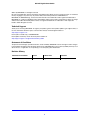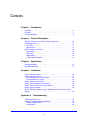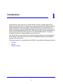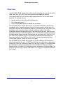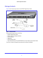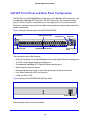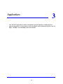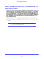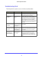
1
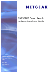
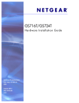
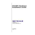
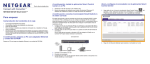
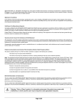
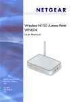
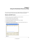
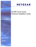
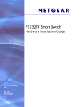
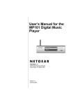
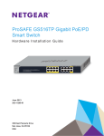
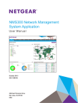
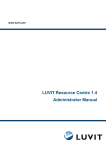
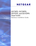
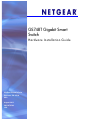
GS748T Gigabit Smart
Switch
H a rdwa re In stallation G u id e
350 East Plumeria Drive
San Jose, CA 95134
USA
August 2012
202-10725-02
v2.0
GS748T Gigabit Smart Switch
©2012 by NETGEAR, Inc. All rights reserved
No part of this publication may be reproduced, transmitted, transcribed, stored in a retrieval system, or translated
into any language in any form or by any means without the written permission of NETGEAR, Inc.
NETGEAR, the NETGEAR logo, and Connect with Innovation are trademarks and/or registered trademarks of
NETGEAR, Inc. and/or its subsidiaries in the United States and/or other countries. Information is subject to change
without notice. Other brand and product names are registered trademarks or trademarks of their respective
holders. ©2012 All rights reserved.
Technical Support
Thank you for choosing NETGEAR. To register your product, get the latest product updates, get support online, or
for more information about the topics covered in this manual, visit the Support website at
http://support.netgear.com
Phone (US & Canada only): 1-888-NETGEAR
Phone (Other Countries): Check the list of phone numbers at
http://support.netgear.com/app/answers/detail/a_id/984
Statement of Conditions
To improve internal design, operational function, and/or reliability, NETGEAR reserves the right to make changes
to the products described in this document without notice. NETGEAR does not assume any liability that may occur
due to the use, or application of, the product(s) or circuit layout(s) described herein.
Revision History
Publication Part Number
Version
Publish Date
Comments
202-10725-02
v2.0
August 2012
Second publication
2
Contents
Chapter 1 Introduction
Overview . . . . . . . . . . . . . . . . . . . . . . . . . . . . . . . . . . . . . . . . . . . . . . . . . . . 6
Features . . . . . . . . . . . . . . . . . . . . . . . . . . . . . . . . . . . . . . . . . . . . . . . . . . . . 7
Package Contents . . . . . . . . . . . . . . . . . . . . . . . . . . . . . . . . . . . . . . . . . . . . 8
Chapter 2 Physical Description
GS748T Front-Panel and Back-Panel Configuration . . . . . . . . . . . . . . . . . 10
LED Designations. . . . . . . . . . . . . . . . . . . . . . . . . . . . . . . . . . . . . . . . . . . . 11
Port LEDs . . . . . . . . . . . . . . . . . . . . . . . . . . . . . . . . . . . . . . . . . . . . . . . . 11
System LED . . . . . . . . . . . . . . . . . . . . . . . . . . . . . . . . . . . . . . . . . . . . . . 11
Device Hardware Interfaces . . . . . . . . . . . . . . . . . . . . . . . . . . . . . . . . . . . . 12
RJ-45 Ports. . . . . . . . . . . . . . . . . . . . . . . . . . . . . . . . . . . . . . . . . . . . . . . 12
SFP Ports . . . . . . . . . . . . . . . . . . . . . . . . . . . . . . . . . . . . . . . . . . . . . . . . 12
Reset Button. . . . . . . . . . . . . . . . . . . . . . . . . . . . . . . . . . . . . . . . . . . . . . 13
Factory Defaults Button . . . . . . . . . . . . . . . . . . . . . . . . . . . . . . . . . . . . . 13
Chapter 3 Applications
Desktop Switching . . . . . . . . . . . . . . . . . . . . . . . . . . . . . . . . . . . . . . . . . . . 16
Backbone Switching . . . . . . . . . . . . . . . . . . . . . . . . . . . . . . . . . . . . . . . . . . 17
Chapter 4 Installation
Step 1: Prepare the Site . . . . . . . . . . . . . . . . . . . . . . . . . . . . . . . . . . . . . . . 20
Step 2: Install the Switch . . . . . . . . . . . . . . . . . . . . . . . . . . . . . . . . . . . . . . 21
Install the Switch on a Flat Surface . . . . . . . . . . . . . . . . . . . . . . . . . . . . 21
Install the Switch in a Rack. . . . . . . . . . . . . . . . . . . . . . . . . . . . . . . . . . . 21
Step 3: Check the Installation. . . . . . . . . . . . . . . . . . . . . . . . . . . . . . . . . . . 22
Step 4: Connect Devices to the Switch . . . . . . . . . . . . . . . . . . . . . . . . . . . 23
Step 5: Install an SFP Transceiver Module . . . . . . . . . . . . . . . . . . . . . . . . 24
Step 6: Apply AC Power . . . . . . . . . . . . . . . . . . . . . . . . . . . . . . . . . . . . . . . 25
Step 7: Manage the Switch using a Web Browser or the Smart Control
Center. . . . . . . . . . . . . . . . . . . . . . . . . . . . . . . . . . . . . . . . . . . . . . . . . . . . . 26
Appendix A Troubleshooting
Troubleshooting Chart . . . . . . . . . . . . . . . . . . . . . . . . . . . . . . . . . . . . . . . . 28
Additional Troubleshooting Suggestions . . . . . . . . . . . . . . . . . . . . . . . . . . 29
Network Adapter Cards . . . . . . . . . . . . . . . . . . . . . . . . . . . . . . . . . . . . . 29
Configuration . . . . . . . . . . . . . . . . . . . . . . . . . . . . . . . . . . . . . . . . . . . . . 29
3
GS748T Gigabit Smart Switch
Switch Integrity . . . . . . . . . . . . . . . . . . . . . . . . . . . . . . . . . . . . . . . . . . . . 29
Auto-Negotiation. . . . . . . . . . . . . . . . . . . . . . . . . . . . . . . . . . . . . . . . . . . 29
Appendix B Technical Specifications
Appendix C Notification of Compliance
Index
4
1.
Introduction
1
Congratulations on the purchase of your NETGEAR® ProSafeTM GS748T Gigabit Smart
Switch! Your GS748T switch is a state-of-the-art, high-performance, IEEE-compliant network
solution designed for users who require a large number of ports and want the power of
Gigabit connectivity to eliminate bottlenecks, boost performance, and increase productivity.
There are 48 twisted-paired ports with 4 SFP GBIC slots (two SFP slots are combo ports) on
the front panel of the switch which support non-stop 10/100/1000 networks. To simplify
installation, the switch is shipped ready for use out of the box.
The GS748T Smart Switch Hardware Installation Guide describes how to install and power
on the GS748T. The information in this manual is intended for readers with intermediate
computer and Internet skills.
This chapter serves as an introduction to the GS748T and provides the following information:
•
Overview
•
Features
•
Package Contents
5
GS748T Gigabit Smart Switch
Overview
The NETGEAR GS748T Gigabit Smart Switch provides 48 twisted-pair ports with four built-in
Small Form Factor (SFP) GBIC slots that support nonstop 1000M fiber networks.
Using these Gigabit slots, you can create high-speed connections to a server or network
backbone. For example, you can:
•
Connect switches to each other with high-speed links
•
Link to high-speed servers
•
Provide 10/100/1000M copper and 1000M fiber connectivity
The NETGEAR GS748T Gigabit Smart Switch also provides the benefit of administrative
management with a complete package of features for the observation, configuration, and
control of the network. With a Web-based Graphical User Interface (GUI), the switch’s many
capabilities can be viewed and used in a simple and intuitive manner. The switch’s
management features include configuration for port and switch information, VLAN for traffic
control, port trunking for increased bandwidth, Class of Service (CoS) for traffic prioritization,
IPv6 Management support to enable IPv6 operation over the network port, IPv6 QoS, IPv6
ACL, static routing, and EEE support. These features provide better understanding and
control of the network. Initial discovery of the switch on the network requires the Smart
Control Center program, a utility that runs on a computer.
The NETGEAR GS748T Gigabit Smart Switch can be free standing or rack mounted in a
wiring closet or equipment room. It is IEEE-compliant and offers low latency for high-speed
networking. All ports can automatically negotiate to the highest speed. This capability makes
the switch ideal for environments that have a mix of Ethernet, Fast Ethernet, or Gigabit
Ethernet devices. In addition, all RJ-45 ports operate in half-duplex or full-duplex mode. The
maximum segment length is 328 feet (100 meters) over Category 5 Unshielded Twisted-Pair
(UTP) cable.
6
GS748T Gigabit Smart Switch
Features
The following list identifies the key features of the GS748T:
•
Forty-eight 10/100/1000 Mbps auto-sensing Gigabit-Ethernet switching ports.
•
Two SFP combo ports.
•
Two dedicated 1000M SFP fiber ports.
•
Full NETGEAR Smart Switch functionality.
•
Full compatibility with IEEE standards:
•
IEEE 802.3i (10BASE-T)
•
IEEE 802.3u (100BASE-TX)
•
IEEE 802.3ab (1000BASE-T)
•
IEEE 802.3z (1000BASE-x)
•
IEEE 802.3az (Energy Efficient Ethernet)
•
IEEE 802.3x (Full-duplex flow control)
•
Autosensing and auto-negotiating capabilities for all ports.
•
Auto Uplink™ on all ports to make the right connection.
•
Automatic address learning function to build the packet-forwarding information table. The
table contains up to 8K Media Access Control (MAC) addresses.
•
Store-and-Forward transmission to remove bad packets from the network.
•
Full-duplex IEEE 802.3x pause frame flow control.
•
Active flow control to minimize packet loss and frame drops.
•
Half-duplex backpressure control.
•
Per port LEDs and power LED.
•
Internal power supply.
•
Standard NETGEAR 7xx series chassis.
•
NETGEAR Green product series power-saving features:
•
Automatic power consumption adjustment based on the RJ-45 cable length.
•
Per port automatic power down when the port link is down.
•
Energy Efficient Ethernet (EEE), defined by IEEE 802.3az, supports operation in a
Low Power Mode.
7
GS748T Gigabit Smart Switch
Package Contents
Figure 1 shows the package contents of the GS748T Gigabit Smart Switch.
GS748T
1
2
3
4
5
6
7
8
9
10
11
12
13
14
15
16
17
18
19
20
21
22
23
24
25
26
27
28
29
30
Reset
Power
31
32
33
34
35
36
37
38
39
40
41
42
43
44
45T
46T
47T
48T
Combo
Ports
47F
49
48F
50
LED Link/Act Mode Green=Link at 1000M Yellow=Link at 100/10M Blink=ACT
SFP LED
GREEN=
1000Mbps
Blink=ACT
Factory
Default
Figure 1. Package Contents
Verify that the package contains the following:
•
GS748T Gigabit Smart Switch
•
Rubber footpads for tabletop installation
•
Rackmounting kits
•
Power cord
•
Quick Installation guide
•
Smart Switch Resource CD with NETGEAR Smart Control Center and Installation Guide
If any item is missing or damaged, contact the place of purchase immediately.
8
2.
Physical Description
2
This chapter describes the GS748T Gigabit Smart Switch hardware features. Topics include:
•
GS748T Front-Panel and Back-Panel Configuration
•
LED Designations
•
Device Hardware Interfaces
9
GS748T Gigabit Smart Switch
GS748T Front-Panel and Back-Panel Configuration
The GS748T has 48 10/100/1000 Mbps copper ports, two 1000 Mbps SFP combo ports, and
two dedicated 1000 Mbps SFP fiber ports. The SFP combo ports are shared with copper
ports 47 and 48. If the SFP combo ports are in use, copper ports 47 and 48 are inactive.
Each port is capable of sensing the line speed and negotiating the duplex mode with the link
partner automatically.
Figure 2 illustrates the front panel of the NETGEAR GS748T.
1000M
SFP Ports
1000M SFP
Combo Ports
Link/Speed/ACT LEDs
Reset Button
GS748T
1
2
3
4
5
6
7
8
9
10
11
12
13
14
15
16
17
18
19
20
21
22
23
24
25
26
27
28
29
30
31
32
33
34
35
36
37
38
39
40
41
42
43
44
Reset
Power
45T
46T
47T
48T
Combo
Ports
47F
49
48F
50
LED Link/Act Mode Green=Link at 1000M Yellow=Link at 100/10M Blink=ACT
Power/Status LED
10/100/1000 Ethernet Ports
SFP LED
GREEN=
1000Mbps
Blink=ACT
Factory
Default
Factory Defaults
Button
Figure 2. Front Panel
The front panel contains the following:
•
48 RJ-45 connectors for 10/100/1000 Mbps autosensing Gigabit Ethernet switching ports
•
Two SFP combo Gigabit Ethernet switching ports
•
Two dedicated 1000 Mbps SFP Gigabit Ethernet switching ports
•
Reset button to restart the device
•
Recessed default reset button to restore the device back to the factory defaults
•
Link, Speed, and Activity LEDs for each port
•
Power and Status LED
Figure 3 illustrates the NETGEAR GS748T back panel.
Power Connector
Figure 3. Back Panel
The back panel contains a power connector.
10
GS748T Gigabit Smart Switch
LED Designations
Port LEDs
The following table describes the RJ-45, combo, and dedicated SFP port LED designations.
There are two LEDs for each RJ-45 port. Each SFP port has its own indication LED.
LED
Designation
Link/Speed/ACT LED mode for
copper ports 1 to 48:
•
•
•
Link/ACT LED for SFP ports
47 to 50:
•
•
•
Off— No link established.
Solid Green — A valid 1000 Mbps link is established.
Blinking Green — The port is transmitting or receiving packets at
1000 Mbps.
• Solid Yellow — A valid 10/100 Mbps link is established.
• Blinking Yellow — The port is transmitting or receiving packets
at 10/100 Mbps.
If the media for ports 47 and 48 changes to SFP, the port LED for copper
ports 47 and 48 changes to off.
Off — No SFP module link is established
Solid Green — A valid 1000 Mbps SFP module link is established.
Blinking Green — The port is transmitting or receiving packets
at 1000 Mbps.
If the media for ports 47 and 48 changes to copper, the port LED for the
SFP combo ports changes to off.
System LED
The following table describes the system LED designations.
LED
Designation
Power
•
•
Green — Device is powered on, run-time code is up and running
Off — Power is not supplied to the device
11
GS748T Gigabit Smart Switch
Device Hardware Interfaces
RJ-45 Ports
RJ-45 ports are autosensing ports. When inserting a cable into an RJ-45 port, the switch
automatically ascertains the maximum speed (10, 100, or 1000 Mbps) and duplex mode
(half-duplex or full-duplex) of the attached device. All ports support only unshielded or
shielded twisted-pair (UTP or STP) cable terminated with an 8-pin RJ-45 plug.
To simplify the procedure for attaching devices, all RJ-45 ports support Auto Uplink. This
technology allows attaching devices to the RJ-45 ports with either straight-through or
crossover cables. When inserting a cable into the switch’s RJ-45 port, the switch
automatically:
•
Senses whether the cable is a straight-through or crossover cable.
•
Determines whether the link to the attached device requires a “normal” connection (such
as when connecting the port to a computer) or an “uplink” connection (such as when
connecting the port to a router, switch, or hub).
•
Configures the RJ-45 port to enable communications with the attached device, without
requiring user intervention. In this way, the Auto Uplink technology compensates for
setting uplink connections, while eliminating concern about whether to use crossover or
straight-through cables when attaching devices.
SFP Ports
To enable you to have fiber connections on your network, there are four SFP ports that
accommodate standard SFP transceiver modules, which are sold separately. Two SFP ports
are combo ports and share connections with the last two RJ-45 ports. The SFP combo ports
and the shared RJ-45 ports are ports 47 and 48.
Only one type of connection of a combo port can be active at any time. For example, if SFP
port 48 is in use, copper port 48 is not active.
Note: If both connectors of a combo port are connected to other devices,
only the fiber port is active.
SFP ports 49 and 50 are dedicated SFP ports and are not combined with any RJ-45 ports.
12
GS748T Gigabit Smart Switch
Reset Button
The Smart Switch has a Reset button on the front panel to allow you to manually reboot the
switch. This action is equivalent to powering the unit off and back on. The last saved
configuration is loaded into the switch as it resets. To operate the Reset button, insert a
device such as a paper clip into the opening to press the recessed button. The front-panel
LEDs should extinguish and light again as the switch performs its Power On Self Test
(POST).
Factory Defaults Button
The Smart Switch has a Factory Defaults button on the front panel so that you can remove
the current configuration and return the device to its factory settings. When you enable the
Factory Defaults button, all settings including the password, VLAN settings, and port
configurations are removed. To operate the Factory Defaults button, insert a device such as
a paper clip into the opening to press the recessed button for over two seconds.
13
GS748T Gigabit Smart Switch
14
3.
Applications
3
Your GS748T Gigabit Smart Switch is designed to provide flexibility in configuring your
network connections. It can be used as your only network traffic-distribution device or with 10
Mbps, 100 Mbps, and 1000 Mbps hubs and switches.
15
GS748T Gigabit Smart Switch
Desktop Switching
The GS748T can be used as a desktop switch to build a small network that enables users to
have 1000 Mbps access to a file server. With full-duplex enabled, the switch port connected
to the server or computer can provide 2000 Mbps throughput.
GS748T
1
2
3
4
5
6
7
8
9
10
11
12
13
14
15
16
17
18
19
20
21
22
23
24
25
26
27
28
29
30
31
32
33
34
35
36
Reset
Power
`
LED Link/Act Mode Green=Link at 1000M Yellow=Link at 100/10M Blink=ACT
`
`
Figure 4. Desktop Switching
16
37
38
39
40
41
42
43
44
45T
46T
47T
48T
Combo
Ports
47F
49
48F
50
SFP LED
GREEN=
100/
1000Mbps
Blink=ACT
Factory
Default
`
GS748T Gigabit Smart Switch
Backbone Switching
You can use the GS748T Gigabit Smart Switch as a backbone switch in a small network that
gives users high-speed access to servers and other network devices.
GS748T
GS748T
2
1
3
4
5
6
7
8
9
10
11
12
13
14
15
16
17
18
19
20
21
22
23
24
25
26
27
Reset
Power
28
29
30
31
32
33
34
35
36
37
38
39
40
41
42
43
44
45T
46T
47T
48T
Combo
Ports
47F
49
48F
50
LED Link/Act Mode Green=Link at 1000M Yellow=Link at 100/10M Blink=ACT
SFP LED
GREEN=
1000Mbps
Blink=ACT
Factory
Default
Model FS728TP
Model GS108T
`
`
`
Figure 5. Backbone Switching
17
`
`
GS748T Gigabit Smart Switch
18
4.
Installation
4
This chapter describes the installation procedures for your GS748T Gigabit Smart Switch.
Switch installation involves the following steps:
Step 1: Prepare the Site
Step 2: Install the Switch
Step 3: Check the Installation
Step 4: Connect Devices to the Switch
Step 5: Install an SFP Transceiver Module
Step 6: Apply AC Power
Step 7: Manage the Switch using a Web Browser or the Smart Control Center
19
GS748T Gigabit Smart Switch
Step 1: Prepare the Site
Before you install the switch, ensure the operating environment meets the site requirements
in the following table.
Characteristics Requirements
Mounting
•
•
Access
Locate the switch in a position that allows access to the front-panel RJ-45 ports, view the
front-panel LEDs, and access the power connector.
Power source
Provide a power connection cord. Power specifications for the switch are shown in
Appendix A. Ensure the AC outlet is not controlled by a wall switch, which can
accidentally turn off power to the outlet and the switch.
Environmental
•
•
•
•
Desktop installations - Provide a flat table or shelf surface.
Rackmount installations - Use a 19-inch (48.3-centimeter) EIA standard equipment
rack that is grounded and physically secure. The rackmount kit supplied with the
switch is also required.
Temperature - Install the switch in a dry area, with ambient temperature between 0
and 50ºC (32ºF and 122ºF). Keep the switch away from heat sources such as direct
sunlight, warm air exhausts, hot-air vents, and heaters.
Operating humidity - The installation location should have a maximum relative
humidity of 90%, non-condensing.
Ventilation - Do not restrict airflow by covering or obstructing air inlets on the sides
of the switch. Keep at least 2 inches (5.08 centimeters) free on all sides for cooling.
Be sure there is adequate airflow in the room or wiring closet where the switch is
installed.
Operating conditions - Keep the switch at least 6 ft. (1.83 meters) away from
nearest source of electromagnetic noise, such as a photocopy machine.
20
GS748T Gigabit Smart Switch
Step 2: Install the Switch
The GS748T can be used on a flat surface or mounted in a standard network equipment
rack.
Install the Switch on a Flat Surface
The switch ships with four self-adhesive rubber footpads. Stick one rubber footpad on each of
the four concave spaces on the bottom of the switch. The rubber footpads cushion the switch
against shock and vibrations. They also provide ventilation space between stacked switches.
Install the Switch in a Rack
To install the switch in a rack, you need the 19-inch rackmount kit supplied with switch.
1. Attach the supplied mounting brackets to the side of the switch.
2. Insert the screws provided in the rackmount kit through each bracket and into the bracket
mounting holes in the switch.
3. Tighten the screws with a #1 Phillips screwdriver to secure each bracket.
4. Align the mounting holes in the brackets with the holes in the rack, and insert two pan-head
screws with nylon washers through each bracket and into the rack.
5. Tighten the screws with a #2 Phillips screwdriver to secure mounting brackets to the rack.
Figure 6. Rack Mount
21
GS748T Gigabit Smart Switch
Step 3: Check the Installation
Before applying power to the switch, perform the following steps:
•
Inspect the equipment thoroughly.
•
Verify that all cables are installed correctly.
•
Check cable routing to make sure cables are not damaged or creating a safety hazard.
•
Ensure all equipment is mounted properly and securely.
22
GS748T Gigabit Smart Switch
Step 4: Connect Devices to the Switch
The following procedure describes how to connect computers to the switch’s RJ-45 ports.
The GS748T contains Auto Uplink technology, which allows the attaching of devices using
either straight-through or crossover cables.
GS748T
1
2
3
4
5
6
7
8
9
10
11
12
13
14
15
16
17
18
19
20
21
22
23
24
25
26
27
28
29
30
31
32
33
34
35
36
37
38
39
40
41
42
43
Reset
Power
LED Link/Act Mode Green=Link at 1000M Yellow=Link at 100/10M Blink=ACT
`
44
45T
46T
47T
48T
Combo
Ports
47F
49
48F
50
SFP LED
GREEN=
100/
1000Mbps
Blink=ACT
Factory
Default
`
Figure 7. Connect Devices to the Switch
Connect each computer to an RJ-45 network port on the Switch front panel (Figure 7). Use
Category 5 (Cat5) Unshielded Twisted-Pair (UTP) cable terminated with an RJ-45 connector
to make these connections.
Note: Ethernet specifications limit the cable length between the switch and
the attached device to 100m (328 ft.).
23
GS748T Gigabit Smart Switch
Step 5: Install an SFP Transceiver Module
The following procedure describes how to install an optional SFP transceiver module into one
of the SFP ports of the switch.
Note: Contact your NETGEAR sales office to buy these modules. If you do
not want to install an SFP module, skip this procedure.
To install an SFP transceiver, insert the transceiver into the SFP port. Press firmly on the
flange of the module to seat it securely into the connector. You can install up to three
additional Gigabit Ethernet modules using this procedure.
GS748T
1
2
3
4
5
6
7
8
9
10
11
12
13
14
15
16
17
18
19
20
21
22
23
24
25
26
27
28
29
30
31
32
33
34
Reset
Power
LED Link/Act Mode Green=Link at 1000M Yellow=Link at 100/10M Blink=ACT
Figure 8. Install an SFP Transceiver Module
24
35
36
37
38
39
40
41
42
43
44
45T
46T
47T
48T
Combo
Ports
47F
49
48F
50
5
0
SFP LED
GREEN=
1000Mbps
Blink=ACT
Factory
Default
GS748T Gigabit Smart Switch
Step 6: Apply AC Power
The GS748T Gigabit Smart Switch does not have an ON/OFF switch. Power must be
controlled by the power cord connection.
Before connecting the power cord, select an AC outlet that is not controlled by a wall switch,
which can turn off power to the switch. After selecting an appropriate outlet, use the following
procedure to apply AC power:
1. Connect the end of the power connection cable to the power receptacle on the back of
the switch.
2. Connect the AC power connection cable into a power source such as a wall socket or
power strip.
When applying power, the green Power LED on the switch’s front panel illuminates.
If the Power LED does not go on, check that the power cable is plugged in correctly and that
the power source is good. If this does not resolve the problem, refer to Appendix A.
25
GS748T Gigabit Smart Switch
Step 7: Manage the Switch using a Web Browser or the
Smart Control Center
The GS748T contains software for viewing, changing, and monitoring the way it works. This
management software is not required for the switch to work. The ports can be used without
using the management software. However, the management software enables the setup of
VLAN and trunking features, IPv6 management support to enable IPv6 operation over the
network port, IPv6 QoS (ACL), static routing, EEE support, and also improves the efficiency
of the switch, which results in the improvement of its overall performance as well as the
performance of the network.
After powering up the switch for the first time, the Smart Switch can be configured using a
Web browser or a program called Smart Control Center. For more information about
managing the switch, see the GS748T Software Administration Manual on the Smart Switch
Resource CD.
Note: The switch is configured with a default IP address of 192.168.0.239
and a subnet mask of 255.255.255.0.
26
A.
Troubleshooting
A
This chapter provides information about troubleshooting the NETGEAR Smart Switch.
Topics include the following:
•
Troubleshooting Chart
•
Additional Troubleshooting Suggestions
27
GS748T Gigabit Smart Switch
Troubleshooting Chart
The following table lists symptoms, causes, and solutions of possible problems.
Symptom
Cause
Solution
Power LED is off.
No power is received.
Check the power cord connections and the
connected device. Ensure all cables used are correct
and comply with Ethernet specifications.
Link LED is off or
intermittent.
Port connection is not
working.
Check the crimp on the connectors and make sure
that the plug is properly inserted and locked into the
port at both the switch and the connecting device.
Ensure all cables used are correct and comply with
Ethernet specifications. Check for a defective
computer adapter card, cable, or port by testing them
in an alternate environment where all products are
functioning.
File transfer is slow or
Half-duplex or full-duplex Make sure the attached device is set to
performance degradation setting on the switch and auto-negotiate.
is a problem.
the connected device are
not the same.
A segment or device is
not recognized as part of
the network.
One or more devices are
not properly connected,
or cabling does not meet
Ethernet guidelines.
Verify that the cabling is correct. Ensure all
connectors are securely positioned in the required
ports. Equipment may have been accidentally
disconnected.
ACT LED is flashing
continuously on all
connected ports and the
network is disabled.
A network loop
(redundant path) has
been created.
Break the loop by ensuring that there is only one
path from any networked device to any other
networked device. After you connect to the switch
management interface, you can configure the
Spanning Tree Protocol (STP) to prevent network
loops.
28
GS748T Gigabit Smart Switch
Additional Troubleshooting Suggestions
If the suggestions in Troubleshooting Chart do not resolve the problem, refer to the
troubleshooting suggestions in this section.
Network Adapter Cards
Ensure the network adapter cards installed in the computers are in working condition and the
software driver has been installed.
Configuration
If problems occur after altering the network configuration, restore the original connections
and determine the problem by implementing the new changes, one step at a time. Ensure
that cable distances, repeater limits, and other physical aspects of the installation do not
exceed the Ethernet limitations.
Switch Integrity
If required, verify the integrity of the switch by resetting the switch. To reset the switch,
remove the AC power from the switch and then reapply AC power. If the problem continues,
contact NETGEAR technical support. In North America, call 1-888-NETGEAR. If you are
outside of North America, please refer to the support information card included with your
product.
Auto-Negotiation
The RJ-45 ports negotiate the correct duplex mode, speed, and flow control if the device at
the other end of the link supports auto negotiation. If the device does not support auto
negotiation, the switch determines only the speed correctly, and the duplex mode defaults to
half-duplex.
29
GS748T Gigabit Smart Switch
30
B.
Technical Specifications
Network Protocol and Standards Compatibility
IEEE 802.3 10BASE-T
IEEE 802.3u 100BASE-TX
IEEE 802.3ab 1000BASE-T
IEEE 802.3z 1000BASE-X
IEEE 802.3az (Energy Efficient Ethernet)
IEEE 802.3x full-duplex flow control
Management
Windows 2000 + XP, Vista; Windows 7, Microsoft Explorer 7.0 or above
IEEE 802.1Q VLAN
IEEE 802.3ad Link Aggregation
IEEE 802.1D Spanning Tree Protocol
IEEE 802.1w Rapid Spanning Tree Protocol
IEEE 802.1s MSTP
IEEE 802.1X Port Security
IEEE 802.1AB LLDP
SNMP v1, v2c, and v3
HTTP and HTTPS
Port Mirroring (RX, TX, and Both)
IGMP Snooping v1/v2/v3
IEEE 802.1p Class of Service (CoS)
SNTP (Simple Network Time Protocol) 3 servers. Disabled by default.
Jumbo Frame Support (9K)
31
B
GS748T Gigabit Smart Switch
Static LAGs
Broadcast Storm Recovery
RMON 1,2,3,9
Static L2 Multicast Filtering
Voice VLAN
Protected Ports
DHCP Filtering
Cable Test
Syslog (RFC 3164)
Persistent log supported
Port Locking
Denial of Service Protection (control plane)
Denial of Service Protection (data plane)
TACACS+
RADIUS
EAPol Forwarding
BPDU Flooding
Auto VoIP
Auto Video
Auto DoS
ACL Wizard
Management Security
Smart Control Center Discovery
Static Routing
Boot code update
Password management
IPv6 management
Text-based config
Inventory Support (Customized)
Restore Defaults Push Button
Restore Defaults via Web
32
GS748T Gigabit Smart Switch
Standard L2 MIBs support
User ID configuration
Authentication login lists
IPv4 and IPv6 DiffServ
MAC, IPv4 and IPv6 ACL
Dual Image Support
Interface
48 RJ-45 connectors for 10BASE-T, 100BASE-TX, and 1000BASE-T (Auto Uplink™ on all
ports)
Two SFP combo ports for SFP modules
Two dedicated SFP ports for SFP modules
LEDs
Per RJ-45 port: Speed/Link/Activity
Per SFP port: Speed/Link/Activity
Per device: Power
Performance Specifications
Forwarding modes: Store-and-forward
Bandwidth: 100 Gbps
Address database size: 8K media access control (MAC) addresses per system
Mean Time Between Failure (MTBF): greater than 160,000 hours at 25°C
Power Supply
100 VAC–240 VAC/50 Hz–60 Hz, 2.0A Max, universal input
Physical Specifications
Dimensions (H x W x D): 1.7 x 17.3 x10.1/43 x 440 x 257 (in/mm)
Weight: 3.8 kg (8.4 lbs)
Environmental Specifications
Operating temperature: 0°C to 50°C (32°F to 122°F)
Operating humidity: 10% to 90% maximum relative humidity, noncondensing
33
GS748T Gigabit Smart Switch
Storage temperature: –20°C to 70°C (–4°F to 158°F)
Storage humidity: 5% to 95% maximum relative humidity, noncondensing
Electromagnetic Emissions
CE Class A, including EN 55022 (CISPR 22), EN 55024, and EN 50082-1
FCC Part 15 Class A
VCCI Class A
C-Tick
KC
Safety
UL/cUL
CE EN 60950-1
34
C.
Notification of Compliance
NETG EA R Wire d Products
C
Regulatory Compliance Information
This section includes user requirements for operating this product in accordance with National
laws for usage of radio spectrum and operation of radio devices. Failure of the end-user to
comply with the applicable requirements may result in unlawful operation and adverse action
against the end-user by the applicable National regulatory authority.
This product's firmware limits operation to only the channels allowed in a particular Region or
Country. Therefore, all options described in this user's guide may not be available in your version
of the product.
FCC Requirements for Operation in the United States
FCC Information to User
This product does not contain any user serviceable components and is to be used with
approved antennas only. Any product changes or modifications will invalidate all applicable
regulatory certifications and approvals
This device complies with Part 15 of the FCC Rules. Operation is subject to the following two
conditions: (1) This device may not cause harmful interference, and (2) this device must
accept any interference received, including interference that may cause undesired operation.
FCC Guidelines for Human Exposure
This equipment complies with FCC radiation exposure limits set forth for an uncontrolled
environment. This equipment should be installed and operated with minimum distance of 20
cm between the radiator and your body.
This transmitter must not be co-located or operating in conjunction with any other antenna or
transmitter.
FCC Declaration Of Conformity
We, NETGEAR, Inc., 350 East Plumeria Drive, San Jose, CA 95134, declare under our sole
responsibility that the GS748T Gigabit Smart Switch complies with Part 15 of FCC Rules.
Operation is subject to the following two conditions:
•
This device may not cause harmful interference, and
35
GS748T Gigabit Smart Switch
•
This device must accept any interference received, including interference that may cause
undesired operation.
FCC Radio Frequency Interference Warnings & Instructions
This equipment has been tested and found to comply with the limits for a Class B digital
device, pursuant to Part 15 of the FCC Rules. These limits are designed to provide
reasonable protection against harmful interference in a residential installation. This
equipment uses and can radiate radio frequency energy and, if not installed and used in
accordance with the instructions, may cause harmful interference to radio communications.
However, there is no guarantee that interference will not occur in a particular installation.
If this equipment does cause harmful interference to radio or television reception, which can
be determined by turning the equipment off and on, the user is encouraged to try to correct
the interference by one or more of the following methods:
•
Reorient or relocate the receiving antenna.
•
Increase the separation between the equipment and the receiver.
•
Connect the equipment into an electrical outlet on a circuit different from that which the
radio receiver is connected.
•
Consult the dealer or an experienced radio/TV technician for help.
Modifications made to the product, unless expressly approved by NETGEAR, Inc., could void
the user's right to operate the equipment.
Canadian Department of Communications Radio Interference Regulations
This digital apparatus, GS748T Gigabit Smart Switch, does not exceed the Class B limits for
radio-noise emissions from digital apparatus as set out in the Radio Interference Regulations of
the Canadian Department of Communications.
This Class [B] digital apparatus complies with Canadian ICES-003.
Cet appareil numérique de la classe [B] est conforme à la norme NMB-003 du Canada
European Union
The GS748T Gigabit Smart Switch complies with essential requirements of EU EMC Directive
2004/108/EC and Low Voltage Directive 2006/95/EC as supported by applying the following test
methods and standards:
•
EN55022: 2006 / A1: 2007
•
EN55024: 1998 / A1: 2001 / A2: 2003
•
EN60950-1: 2005 2nd Edition
•
EN 61000-3-2:2006
•
EN 61000-3-3:1995 w/A1: 2001+A2: 2005
36
Index
Numerics
I
1U 7
8-pin 12
IEEE 802.3x 7
IEEE Standards 7
IEEE-compliant 6
Installation Guide 8
Installing the Switch 21
A
Applying AC Power 25
Auto Uplink 12
Auto-negotiating 7
Autosensing 12
L
LED Designations 11
Low Latency 6
B
Backpressure 7
M
C
MAC 7
Media Access Control 7
Category 5 Unshielded Twisted-Pair 6
Checking the Installation 22
Class of Service 6
compliance 35
Connecting Devices to the Switch 23, 24
Crossover 12
O
Operating Conditions 20
Operating Environment 20
Operating humidity 20
Overview 6
D
P
Default Reset Button 10
Device Hardware Interfaces 12
Duplex Mode 12
Package Contents 8
Pause Frame Flow Control 7
Port LEDs 11
Preparing the Site 20
F
R
Factory Default Button 13
Factory Defaults 10
Flat Surface 21
Full-duplex 6
Rackmount kit 8
Reset Button 10
RJ-45 Ports 12
RJ-45 ports 6
Rubber footpads 8, 21
G
Gigabit Ports 6
S
Smart Switch Resource CD 8
Straight-through 12
37
GS748T Gigabit Smart Switch
System LEDs 11
T
technical support 2
Temperature 20
trademarks 2
Traffic Control 6
Troubleshooting Chart 28
U
User Intervention 12
User’s Manual 8
UTP 23
V
Ventilation 20
VLAN 6, 26
W
Web-based Graphical User Interface 6
38