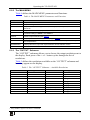
1
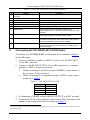
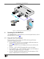
Kramer Electronics, Ltd. USER MANUAL Models: VP-420, PC/HD Scaler VP-421, PC/HD Scaler Contents Contents 1 2 2.1 3 4 4.1 4.2 5 6 6.1 6.2 Introduction Getting Started Quick Start Overview Your PC/HD Scaler Your VP-420 PC/HD Scaler Your VP-421 PC/HD Scaler Connecting the VP-420/VP-421 PC/HD Scaler Operating the VP-420/VP-421 Using the Front Panel Buttons Using the OSD Using the Front Panel Buttons The MAIN MENU The “OUTPUT” Submenu The “OSD” Submenu 8 9 9 10 7 Technical Specifications 10 6.2.1 6.2.2 6.2.3 6.2.4 1 1 2 3 4 4 5 6 7 7 8 Figures Figure 1: VP-420 PC/HD Scaler – Front and Rear View Figure 2: VP-421 PC/HD Scaler – Front and Rear View Figure 3: Connecting the VP-420 PC/HD Scaler 4 5 7 Tables Table 1: VP-420 PC/HD Scaler Front Panel Features Table 2: VP-421 PC/HD Scaler Front Panel Features Table 3: 15-pin HD PINOUT for HD Table 4: The MAIN MENU Parameters and Functions Table 5: The “OUTPUT” Submenu – Available Resolutions Table 6: The “OSD” Submenu – Available Adjustments Table 7: Technical Specifications of the VP-420/VP-421 PC/HD Scaler 5 6 6 9 9 10 10 i Introduction 1 Introduction Welcome to Kramer Electronics! Since 1981, Kramer Electronics has been providing a world of unique, creative, and affordable solutions to the vast range of problems that confront the video, audio, presentation, and broadcasting professional on a daily basis. In recent years, we have redesigned and upgraded most of our line, making the best even better! Our 1,000-plus different models now appear in 11 groups 1 that are clearly defined by function. Thank you for purchasing your Kramer VP-420 or VP-421 PC/HD Scaler. These products are ideal for: • Projection systems in conference rooms, boardrooms, hotels and churches • Home theater up-scaling The package includes the following items: • VP-420 or VP-421 PC/HD Scaler • Power adapter (5V DC input) • This user manual 2 2 Getting Started We recommend that you: • Unpack the equipment carefully and save the original box and packaging materials for possible future shipment • Review the contents of this user manual • Use Kramer high-performance high-resolution cables 3 1 GROUP 1: Distribution Amplifiers; GROUP 2: Switchers and Matrix Switchers; GROUP 3: Control Systems; GROUP 4: Format/Standards Converters; GROUP 5: Range Extenders and Repeaters; GROUP 6: Specialty AV Products; GROUP 7: Scan Converters and Scalers; GROUP 8: Cables and Connectors; GROUP 9: Room Connectivity; GROUP 10: Accessories and Rack Adapters; GROUP 11: Sierra Products 2 Download up-to-date Kramer user manuals from the Internet at http://www.kramerelectronics.com 3 The complete list of Kramer cables is on our Web site at http://www.kramerelectronics.com 1 Getting Started 2.1 Quick Start This quick start chart summarizes the basic setup and operation steps. 2 KRAMER: SIMPLE CREATIVE TECHNOLOGY Overview 3 Overview The Kramer VP-420/VP-421 PC/HD Scaler is a high-performance digital scaler for computer graphics and HDTV signals. It up- or down-scales computer graphics and HDTV signals to resolutions up to WUXGA and 1080p. The following output resolutions are supported: PC: VGA, SVGA, XGA, 1280x800, SXGA, UXGA, WXGA, SXGA+, WXGA+, WSXGA, WUXGA, COMPONENT: 480p, 576p, 720p @50/60Hz, 1080i @50/60Hz, 1080p @50/60Hz. The VP-420/VP-421 PC/HD Scaler also features: • An On-Screen Display (OSD) for easy setup and adjustment, accessible via the front-panel buttons • A built-in ProcAmp for convenient signal adjustment • A non-volatile memory that retains the last settings used • Quick auto-adjust • Freeze button • RGBHV or component video input and/or output The machine is fed from an external 5V DC source, making it suitable for field operation. Operate your VP-420/VP-421 directly via the front panel push buttons and the on-screen display (OSD). To achieve the best performance: • Use only good quality connection cables 1 to avoid interference, deterioration in signal quality due to poor matching, and elevated noise levels (often associated with low quality cables) • Avoid interference from neighboring electrical appliances that may adversely influence signal quality and position your Kramer VP-420/VP-421 away from moisture, excessive sunlight and dust 1 Available from Kramer Electronics on our Web site at http://www.kramerelectronics.com 3 Your PC/HD Scaler 4 Your PC/HD Scaler For a description of the: • VP-420 PC/HD Scaler, see section 4.1 • VP-421 PC/HD Scaler, see section 4.2 4.1 Your VP-420 PC/HD Scaler Figure 1 and Table 1 define the VP-420 PC/HD Scaler: Figure 1: VP-420 PC/HD Scaler – Front and Rear View 4 KRAMER: SIMPLE CREATIVE TECHNOLOGY Your PC/HD Scaler Table 1: VP-420 PC/HD Scaler Front Panel Features 2 3 4 5 6 Feature PC/HD OUTPUT 15-pin HD connector PC/HD INPUT 15-pin HD connector 5V DC ON LED COMPONENT OUT LED MENU button 7 ENTER button 8 – /AUTO ADJUST button 9 +/FREEZE button 1 # 4.2 Function Connects to computer graphics or HDTV acceptor Connects to computer graphics or HDTV source +5V DC connector for powering the unit Lights when the unit is powered on Lights when component video is output Press to enter/escape the on-screen display (OSD) menu. Press together with the – button to reset to 720p In OSD, press to choose the highlighted menu item. Press together with the + button to reset to XGA In OSD, press to move backward through the list or to decrement the parameter value. When not in OSD, press to automatically adjust the picture to fit the display In OSD, press to move forward through the list or to increment the parameter value. When not in OSD, press to freeze the display Your VP-421 PC/HD Scaler Figure 2 and Table 2 define the VP-421 PC/HD Scaler: Figure 2: VP-421 PC/HD Scaler – Front and Rear View 5 Connecting the VP-420/VP-421 PC/HD Scaler Table 2: VP-421 PC/HD Scaler Front Panel Features 2 3 4 5 6 7 Feature PC/HD OUTPUT 15-pin HD connector DVI OUTPUT DVI connector PC/HD INPUT 15-pin HD connector 5V DC ON LED COMPONENT OUT LED MENU button 8 ENTER button 9 – /AUTO ADJUST button 10 +/FREEZE button 1 # 5 Function Connects to computer graphics or HDTV acceptor Connects to DVI acceptor Connects to computer graphics or HDTV source +5V DC connector for powering the unit Lights when the unit is powered on Lights when component video is output Press to view the on-screen display (OSD) menu. Press together with the – button to reset the display to 720p resolution In OSD, press to choose the highlighted menu item. Press together with the + button to reset to XGA In OSD, press to move backward through the list or to decrement the parameter value. When not in OSD, press to automatically adjust the picture to fit the display In OSD, press to move forward through the list or to increment the parameter value. When not in OSD, press to freeze the display Connecting the VP-420/VP-421 PC/HD Scaler To connect your VP-420/VP-421, as illustrated in the example in Figure 3 do the following: 1. Connect a computer graphics or HDTV source to the PC/HD INPUT 15-pin HD connector. 2. Connect to the PC/HD OUTPUT 15-pin HD connector to a computer graphics or HDTV acceptor as follows: When connecting to an XGA acceptor (RGBHV), then connect to the acceptor’s XGA connector When connecting to a component acceptor (YPbPr), then connect as shown in Table 3 Table 3: 15-pin HD PINOUT for HD PIN # 1 2 3 6, 7, 8 Signal Pr Y Pb Ground 3. If connecting a VP-421, connect the DVI OUTPUT to a DVI acceptor 1. 4. Connect the 5V DC power adapter to the power socket and connect the adapter to the mains electricity (not shown in Figure 3). 1 The VP-421 outputs on both the 15-pin HD connector and the DVI connector. You can connect to either output or to both of them simultaneously 6 KRAMER: SIMPLE CREATIVE TECHNOLOGY Operating the VP-420/VP-421 Figure 3: Connecting the VP-420 PC/HD Scaler 6 Operating the VP-420/VP-421 The VP-420/VP-421 is operated directly via the front panel buttons, and via the OSD menu (see section 6.2). 6.1 Using the Front Panel Buttons During normal operation (without the OSD), the front panel buttons perform the following functions: • Pressing MENU opens the on-screen display (OSD) main menu (see section 6.2), the next press closes the OSD • Pressing +/FREEZE freezes the display, the next press unfreezes the display • Pressing – /AUTO ADJUST automatically centers the display • Pressing MENU and –/AUTO ADJUST together resets the display to 720p and the COMPONENT OUT LED lights • Pressing +/FREEZE and ENTER together resets the display to XGA and the COMPONENT OUT LED turns off 7 Operating the VP-420/VP-421 6.2 Using the OSD You can use the OSD to set a wide variety of parameters. When the MENU button is pressed, the main menu opens allowing access to all the device settings (see Table 4). When setting FINETUNE, COLOR, SIZE, OUTPUT (see Table 5), and OSD (see Table 6) a submenu opens with the applicable parameters. 6.2.1 Using the Front Panel Buttons While the OSD is open, the front panel buttons perform the following functions: • Pressing + and – move forward and backward through the menu items and increment or decrement the parameter values • Pressing ENTER selects and activates a menu item or accepts the parameter value set • Pressing MENU closes the OSD menu 1 As an example of setting parameters, to increase the contrast on the display: 1. From normal operation, press MENU. The OSD main menu appears on the screen. 2. Press the + or – button to highlight CONTRAST. CONTRAST changes to green when highlighted. 3. Press ENTER. The contrast value parameter changes to red. 4. Press the + button to increase the value (increase the contrast) or the – button to decrease the value (decrease the contrast). The value ranges from 0 to 100. 5. Press ENTER to set the value. The contrast value parameter changes back to white. 6. To return to normal operation, highlight EXIT and press ENTER, press MENU, or wait until the menu times out. 1 The menu times out by default after 10 seconds. To change the OSD display time, adjust the OSD/TIMER parameter 8 KRAMER: SIMPLE CREATIVE TECHNOLOGY Operating the VP-420/VP-421 6.2.2 The MAIN MENU Table 4 defines the MAIN MENU parameters and functions. Table 4: The MAIN MENU Parameters and Functions Parameter CONTRAST Function Adjusts the contrast BRIGHTNESS Adjusts the brightness FINETUNE Adjusts the other ProcAmp parameters, for example, hue, sharpness, noise reduction, and so on COLOR Adjusts the color of the display – RED, GREEN, BLUE SIZE Select the size of the display: LETTER BOX, PANSCAN, FULL, OVERSCAN, and two underscan settings: UNDER 1 and UNDER 2 OUTPUT Sets the output resolution (see Table 5) OSD FACTORY RESET Adjusts parameters of the on-screen display (see Table 6) Resets the device to its factory default parameters and automatically senses the input and output devices INFORMATION Displays the source, input and output resolutions and the software version EXIT Select to exit the OSD 6.2.3 The “OUTPUT” Submenu The “OUTPUT” submenu allows you to choose the output resolution sent to the display. Each press of the + or – button cycles through the list of resolutions. Table 5 defines the resolutions available on the “OUTPUT” submenu and how they appear on the display. Table 5: The “OUTPUT” Submenu – Available Resolutions VGA SVGA Parameter Appears As 640x480 800x600 Parameter WUXGA 480P Appears As 1920x1200 480p XGA 1024x768 576P 576p 1280x800 1280x800 720P50 720p @50Hz SXGA 1280x1024 720P60 720p @60Hz UXGA 1600x1200 1080P50 1080p @50Hz WXGA 1366x768 1080P60 1080p @60Hz SXGA+ 1400x1050 1080p (RGBHV) 1 1920x1080 WXGA+ 1440x900 1080I50 1080i @50Hz WSXGA 1680x1050 1080I60 1080i @60Hz 1 1080p (RGBHV) appears in the Menu as 1080PRGB 9 Technical Specifications 6.2.4 The “OSD” Submenu The “OSD” submenu allows you to adjust the location of the OSD, the length of time it is displayed, and the darkness of its background (see Table 6). Table 6: The “OSD” Submenu – Available Adjustments Parameter H-POSITION V-POSITION Function Adjusts the horizontal position of the OSD on the screen Adjusts the vertical position of the OSD on the screen Range 0–100 0–100 Default 50 50 TIMER Adjusts the length of time in seconds the OSD appears on the screen 0–100 10 BACKGROUND Adjusts the shade of the OSD background from black to transparent 0–8 4 EXIT Select to exit to the Main Menu 7 Technical Specifications 1 Table 7: Technical Specifications of the VP-420/VP-421 PC/HD Scaler INPUTS: OUTPUT: OUTPUT RESOLUTIONS 2: OUTPUT REFRESH RATE: PROCESSING DELAY: CONTROLS: POWER SOURCE: DIMENSIONS: WEIGHT: ACCESSORIES: OPTIONS: 1 PC/HD on a 15-pin HD connector, RGBHV/YPbPr 1 PC/HD on a 15-pin HD connector, RGBHV/YPbPr 1 DVI on a DVI connector (VP-421 only) PC: VGA, SVGA, XGA, 1280x800, SXGA, UXGA, WXGA, SXGA+, WXGA+, WSXGA, WUXGA, COMPONENT: 480p, 576p, 720p @50/60Hz, 1080i @50/60Hz, 1080p @50/60Hz 60Hz for computer graphics resolutions, 50/60Hz for HDTV resolutions 3 frames Front panel buttons, ON and COMPONENT OUTPUT LEDs VP-420: 5V DC, 800mA; VP-421: 5V DC, 1A 19cm x 13.5cm x 2.5cm (7.5” x 5.3” x 0.98”) W, D, H 0.66kg (1.45lbs) approx. Power supply 19" rack adapter 1 Specifications are subject to change without notice 2 All resolutions are outputted @ 60Hz, except where noted 10 KRAMER: SIMPLE CREATIVE TECHNOLOGY LIMITED WARRANTY Kramer Electronics (hereafter Kramer) warrants this product free from defects in material and workmanship under the following terms. HOW LONG IS THE WARRANTY Labor and parts are warranted for three years from the date of the first customer purchase. WHO IS PROTECTED? Only the first purchase customer may enforce this warranty. WHAT IS COVERED AND WHAT IS NOT COVERED Except as below, this warranty covers all defects in material or workmanship in this product. The following are not covered by the warranty: 1. Any product which is not distributed by Kramer, or which is not purchased from an authorized Kramer dealer. If you are uncertain as to whether a dealer is authorized, please contact Kramer at one of the agents listed in the Web site www.kramerelectronics.com. 2. Any product, on which the serial number has been defaced, modified or removed, or on which the WARRANTY VOID IF TAMPERED sticker has been torn, reattached, removed or otherwise interfered with. 3. Damage, deterioration or malfunction resulting from: i) Accident, misuse, abuse, neglect, fire, water, lightning or other acts of nature ii) Product modification, or failure to follow instructions supplied with the product iii) Repair or attempted repair by anyone not authorized by Kramer iv) Any shipment of the product (claims must be presented to the carrier) v) Removal or installation of the product vi) Any other cause, which does not relate to a product defect vii) Cartons, equipment enclosures, cables or accessories used in conjunction with the product WHAT WE WILL PAY FOR AND WHAT WE WILL NOT PAY FOR We will pay labor and material expenses for covered items. We will not pay for the following: 1. Removal or installations charges. 2. Costs of initial technical adjustments (set-up), including adjustment of user controls or programming. These costs are the responsibility of the Kramer dealer from whom the product was purchased. 3. Shipping charges. HOW YOU CAN GET WARRANTY SERVICE 1. To obtain service on you product, you must take or ship it prepaid to any authorized Kramer service center. 2. Whenever warranty service is required, the original dated invoice (or a copy) must be presented as proof of warranty coverage, and should be included in any shipment of the product. Please also include in any mailing a contact name, company, address, and a description of the problem(s). 3. For the name of the nearest Kramer authorized service center, consult your authorized dealer. LIMITATION OF IMPLIED WARRANTIES All implied warranties, including warranties of merchantability and fitness for a particular purpose, are limited in duration to the length of this warranty. EXCLUSION OF DAMAGES The liability of Kramer for any effective products is limited to the repair or replacement of the product at our option. Kramer shall not be liable for: 1. Damage to other property caused by defects in this product, damages based upon inconvenience, loss of use of the product, loss of time, commercial loss; or: 2. Any other damages, whether incidental, consequential or otherwise. Some countries may not allow limitations on how long an implied warranty lasts and/or do not allow the exclusion or limitation of incidental or consequential damages, so the above limitations and exclusions may not apply to you. This warranty gives you specific legal rights, and you may also have other rights, which vary from place to place. NOTE: All products returned to Kramer for service must have prior approval. This may be obtained from your dealer. This equipment has been tested to determine compliance with the requirements of: EN-50081: EN-50082: CFR-47: "Electromagnetic compatibility (EMC); generic emission standard. Part 1: Residential, commercial and light industry" "Electromagnetic compatibility (EMC) generic immunity standard. Part 1: Residential, commercial and light industry environment". FCC* Rules and Regulations: Part 15: “Radio frequency devices Subpart B Unintentional radiators” CAUTION! Servicing the machines can only be done by an authorized Kramer technician. Any user who makes changes or modifications to the unit without the expressed approval of the manufacturer will void user authority to operate the equipment. Use the supplied DC power supply to feed power to the machine. Please use recommended interconnection cables to connect the machine to other components. * FCC and CE approved using STP cable (for twisted pair products) 11 For the latest information on our products and a list of Kramer distributors, visit our Web site: www.kramerelectronics.com, where updates to this user manual may be found. We welcome your questions, comments and feedback. Safety Warning: Disconnect the unit from the power supply before opening/servicing. Caution Kramer Electronics, Ltd. Web site: www.kramerelectronics.com E-mail: [email protected] P/N: 2900-000506 REV 4