1
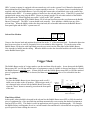
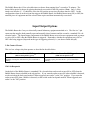
J-KEM® Scientific, Inc.
KEM Scientific, Inc.
6970 Olive Blvd.
St. Louis, MO 63130
(314) 863-5536
Fax (314) 863-6070
E-Mail: [email protected]
Instruments for Science from Scientists
Bubble Buster
User Instructions
The Bubble Buster is designed to turn any piece of electrical equipment such as a HPLC, pump, valve,
or digital I/O lines OFF (or ON) when air is detected in a piece of transparent tubing. Among other uses, the
Bubble Buster can be used to turn off HPLC systems when they run out of solvent or turn on a pump to refill a
solvent reservoir for column chromatography. For computer controlled solvent monitoring systems the Bubble
Buster can be modified to indicate in which of 4 solvent lines air was detected.
For the Bubble Buster to work, you need to do 4 things:
1.
Connect the monitor head to the Bubble Buster
2.
Connect the monitor head to the desired tubing.
3.
Set the trigger mode for either "one-shot" or "timed reset mode".
4.
Electrically connect the piece of equipment you want to control to the Bubble Buster.
Sec.
Min.
N.O.
N.C.
COM
Sensor
Head
7
15
30
1
2
8
16
32
Two styles of monitor heads are available, the HPLC Head
which monitors up to 4 HPLC solvent lines simultaneously and
the Single Line Monitor Head that monitors a single solvent line
of varying diameters. Each head connects to the 6-pin connector
on back of the Bubble Buster.
HPLC Head
Level Head
Connect the Monitor Head
OFF
ON
Head Style Switches
HPLC Monitor Head
Switch Position
Switch Switch
1
2
ON
OFF
The HPLC Monitor Head fits standard 1/8" transparent teflon tubing used on most HPLC systems. Detection
is less efficient with translucent tubing which should be replaced with clear teflon tubing. Tubing for Waters
HPLC systems which is slightly larger than 1/8" fits in the monitor head, but must be flattened a little first.
Remove the nylon cover and foam pad from the grooved end of the monitor head. Place the solvent line
leading from the reservoir bottle into any of the 4 grooved openings on the monitor head. Up to 4 separate
lines can be inserted while any unused positions can remain open. Replace the foam pad and nylon cover and
place the head in a position where it's out of the way and won't be hit causing the detector to false trigger.
Set the timed reset switches (switches 5 - 12) to the off position (see below). There are 2 ways to
establish the electrical connections between the HPLC and the Bubble Buster (see the section that follows).
The best way is to connect the Bubble Busters 3-pin I/O outlet and the HPLC’s external stop terminals. If the
HPLC system (or pump) is equipped with an external stop, refer to the systems User’s Manual to determine if
these terminals need a contact closure or a contact opening to activate. If a contact closure is needed plug the
supplied cable into the Bubble Busters 3-pin I/O plug then connect the red and black wires to the remote stop
terminals on the HPLC. If a contact opening is needed, use the red and white wires. If the HPLC system isn’t
equipped with remote stop, plug the HPLC system (or pumps) into the 120 volt outlet on back of the Bubble
Buster and set the "When triggered, turn outlet:" switch to the "OFF" position.
To verify correct operation of the Bubble Buster, fill all solvent lines then press the reset button on the Bubble
Buster’s front panel. The HPLC system should work normally. Now introduce a bubble into any of the
solvent lines. When the bubble reaches the detection head, the red trouble indicator on the Bubble Buster’s
front panel lights and the HPLC system turns off.
Solvent Line Monitor
Switch Position
Switch Switch
1
2
ON
OFF
Unscrew the detector head and position the solvent line in the ‘V’ of the detection head. Position the detection
head in an area where it won't be frequently hit so as to minimize false triggering. To test the action of the
Bubble Buster, fill the tube with liquid then press the reset switch on the front panel of the Bubble Buster.
Now introduce a bubble into the tubing. When the bubble reaches the detection head the red trouble indicator
on the Bubble Buster lights.
Trigger Mode
Sec.
Min.
N.O.
N.C.
COM
Sensor
Head
7
15
30
1
2
8
16
32
One-Shot Mode.
To place the Bubble Buster in one-shot trigger mode set all 8
timed reset switches to the off position. In this trigger mode, if
air is detected in the solvent line the Bubble Buster resets only
when the "Reset" button is manually pressed on the front panel
of the unit.
HPLC Head
Level Head
The Bubble Buster works in 2 trigger modes, one-shot and time delayed modes. In one-shot mode the Bubble
Buster turns OFF (or ON) the attached piece of equipment as soon as a bubble is detected and keeps it off until
the Bubble Buster is manually reset. In time delayed mode the Bubble Buster turns OFF (or ON) the attached
piece of equipment when a bubble is detected, but then reset automatically after a User selectable time has
passed.
OFF
ON
Timed reset switches
Time Delayed Mode
In this mode, when a bubble is detected in the solvent line the Bubble Buster turns OFF (or ON) the attached
piece of equipment for a User specified time and then automatically resets causing the attached equipment to
turn back ON (or OFF). This mode is useful in applications such as gravity chromatography. For example,
the Bubble Buster could monitor for air in a solvent transfer line and when air is detected turn on a pump for a
specific period of time refilling the reservoir.
The Bubble Buster has 8 User selectable times to choose from ranging from 7 seconds to 32 minutes. The
desired delay period is chosen by placing that timed reset switch to the ON position. (Note: Only 1 of the
timed reset switches (5 - 12) should be set to the ON position at any time, the others must be OFF). In this
configuration when air in the solvent line triggers the Bubble Buster, the Bubble Buster turns ON (or OFF) the
attached piece of equipment until the selected time expires and then automatically resets itself.
Input/Output Options
The Bubble Buster has 2 ways to electrically control laboratory equipment attached to it. The first is a 3 pin
connector that supplies both normally open and normally closed contacts and the second is a standard 120 volt
electrical outlet. The Input/Output components of the Bubble Buster are used to turn equipment such as pumps
or valves ON or OFF when the Bubble Buster is triggered. Remember, whether the equipment stays ON or
OFF after being triggered, depends on the type of triggering selected (i.e., one-shot or timed delayed).
3-Pin Contact Closure.
This is a low voltage relay that operates as described in the table below.
When the Controller is NOT Triggered
(LED on front panel is green)
A connection is made between the COM (common) and N.C.
(Normally Closed) pins while the N.O. pin is connected to
nothing.
When the Controller IS Triggered
(LED on front panel is red)
A connection is made between the COM (common) and N.O.
(Normally Open) pins while the N.C. pin is connected to
nothing.
120 Volt Receptacle
On the back of the Bubble Buster is a standard 120 volt outlet that can be made to turn ON or OFF when the
Bubble Buster detects a bubble in the solvent line. If you want the outlet to turn ON when a bubble is detected,
set the switch on the back panel marked "When triggered, turn outlet:" to the "On" position. If you want the
outlet to turn OFF when a bubble is detected, set the switch on the back panel marked "When triggered, turn
outlet:" to the "Off" position.