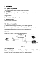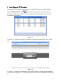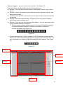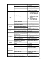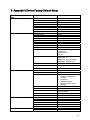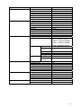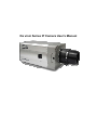
1
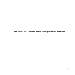
Da vinci Series IP Camera User’s Manual Welcome Thank you for purchasing our IP camera! This user’s manual is designed to be a reference tool for your system. Please read the following safeguards and warnings carefully before you use or install the IP camera. Important Safeguards and Warnings 1.Electrical safety All installation and operation here should conform to local electrical safety codes. We assume no liability or responsibility for all the fires or electrical shock caused by improper handling or installation. 2.Transportation security Heavy stress, violent vibration or water splash are not allowed during transportation, storage and installation. 3.Installation Please make sure the proper ventilation. Do not apply power to the IP camera before completing installation. 4.Qualified engineers needed We are not liable for any problems caused by unauthorized modifications or attempted repair. 5.Environment The IP camera should be installed in a cool, dry place away from direct sunlight, inflammable, explosive substances and etc. The working temperature ranges from 0℃ to +50℃. The IP camera shall be away from the strong electromagnetism radiant, please keep it away from wireless power, TV transmitter and etc. Do not use the IP camera to shoot the shining objects such as the lamplight or sun. The unstable light may result in flashing video. 6. Accessories Be sure to use all the accessories recommended by manufacturer. Before installation, please open the package and check all the components are included: Contact your local retailer ASAP if something is missing in your package. Table of Contents 1 2 Overview ......................................................................................................................................5 1.1 General Introduction ....................................................................................................5 1.2 Features.........................................................................................................................5 Interface .......................................................................................................................................7 2.1 Lens ................................................................................................................................7 2.1.1 2.1.2 2.1.3 2.1.4 2.2 General Lens..........................................................................................................7 Auto Aperture Lens ...............................................................................................7 Lens Installation.....................................................................................................8 Dismantle Lens ......................................................................................................8 Rear Panel.....................................................................................................................9 2.2.1 I/O Socket Operation Introduction ....................................................................13 2.2.2 Alarm Connection and Setup Introduction ......................................................13 3 Installation .................................................................................................................................15 3.1 System Requirement .................................................................................................15 3.2 Hardware Installation .................................................................................................15 3.2.1 LAN........................................................................................................................15 3.2.2 Public Network .....................................................................................................15 4 Auto Search IP Function .........................................................................................................17 5 Network Safety Level Setup ...................................................................................................19 6 Client Operation........................................................................................................................22 6.1 Network Connection...................................................................................................22 6.2 Login and Logout........................................................................................................22 7 Appendix 1 Specification.........................................................................................................26 8 Appendix 2 Function List.........................................................................................................28 9 10 Appendix 3 Device Factory Default Setup ...........................................................................31 Appendix 4 FAQ ................................................................................................................34 1 Overview 1.1 General Introduction This series IP camera combines the traditional camera and network video technology together. It integrates video capture, video process, network transmission and storage. You can just connect it to the network to use without other assistant device. It has one mega resolution and supports PoE, wireless application, audio talk. It also has built-in electronic PTZ, FTP network storage and playback, data watermark and etc. You can connect it to the internet and then configure a client-end program to use. Or you can connect it to the LAN. It is suitable in various environments such as office, bank and road monitor. 1.2 Features User Management Backup Function z z z z z z z z z Alarm Function z z z z z z Network Monitor z z z Network Management z z z z Different user rights for each group, one user belongs to one group. You can freely set monitor right when there is no user login Support central server backup function in accordance with your configuration and setup in alarm or schedule setting Support local record function and backup recorded video in client end. Support SD card hot swap and memory backup function, support short time backup when encounter network connection failure. Storage recorded file and image in the SD card. Support file records transmission and image via FTP. Real-time respond to external alarm input( within 200MS) as user predefined activation setup and exert corresponding message in screen and audio prompt(allow user to pre-record audio file) Provide central management server management option so that system can initiatively send alarm notice remotely. Alarm input can connect with various peripheral equipments. Provide prompt or alarm option when encounter video loss. Reserve 9M for you to record and backup audio and video file Support SMS (short messaging service) function when alarm occurs. When camera masking occurs, system can prompt or alarm as you set. System can alarm or prompt when network disconnection or IP conflict occurs. IPC one-channel audio/video data transmit to network terminal and then decode. Delay within 250 ms (network bandwidth support needed). Max supports 10 connections. Adopt the following audio and video transmission protocol: HTTP 、 TCP、UDP、RTP/RTCP. Send some alarm data or message via SMTP. Support web access, used in WAN. Realize IPC configuration and management via Ethernet. Support web and client -end. Peripheral Equipment Assistant Function z z z z z z z z Support peripheral equipment management, each peripheral equipment control protocol and interface can be set freely. Support serial port(RS485) transparent data transmission Support auto day/nigh mode switch. Support system resource information and running status real-time display. Support log function. Support electronic PTZ, electronic zoom, and direction move. Support auto aperture setup. Support backlight compensation. Realize image zone auto split to add black zone brightness. 2 Interface 2.1 Lens Besides the lens included in package, you can use other CS installation lens. Note: This series IP camera supports CS port only. You need to use a 5mm C/CS lens conversion ring if you want to use a C type lens. 2.1.1 General Lens The lens shall be CS installation type and less than 0.5kg. The rear panel shall be less than 4mm. See Figure 2-1. Figure 2-1 2.1.2 Auto Aperture Lens You can use DC (direct current) auto aperture lens. You need a LENS connection socket if you want to connect to an auto aperture lens. See Figure 2-2. Figure 2-2 Please refer to the following sheet for auto aperture PIN definition. n o p Cap Lens cable Rib(You can cut rib if cable is too thick.) q r s t u Socket(not included in the package) PIN 4:Driver-(ground) PIN 2:Control+ PIN1:Control- PIN 3:Driver+ 2.1.3 Lens Installation Please follow the steps listed below. See Figure 2-3. z Line up the lens to the installation position and turn it clockwise until it is fixed firmly. z Insert lens cable plug into auto lens shutter connector. (Go to step 3 directly if you are installing manual lens.) z You can use slot screwdriver to turn screw to adjust focus if you can not adjust properly when it is ∞ (infinity). Auto aperture lens connector Figure 2-3 2.1.4 Dismantle Lens Please follow the steps listed below to dismantle the lens. See Figure 2-4. z Unplug the lens cable from the auto aperture lens connector. z Turn the lens counter clockwise to remove it from the camera. Auto aperture lens connector Figure 2-4 2.2 Rear Panel Please refer to the following sheet and Figure 2-5 for IP camera interface information. Interface Name VIDEO OUT Video output port Connector Function BNC Output analog video signal. Can connect to TV monitor to view video. Wireless antenna port Connect to wireless antenna to receive WIFI wireless signal. DC 12V Power port. Input 12V DC STATUS Status indication light It is to indicate camera working status: z The red light becomes on when connect the camera to the power. The green light flashes and then becomes on, which means application is running normally. Now you can log in via network. z The indication light becomes off when you reboot the system via software. z The green light flashes when system is recording. z The red light flashes when system is upgrading. z The red light flashed when system is in safety mode. WLAN Wireless network The wireless network indication light indication light is to display wireless network working status. The network indication light becomes green when you connect the IP camera to the wireless network. A RS485 port I/O port RS485_A port, control external PTZ B RS485_B port, control external PTZ 1 1-2ch alarm Alarm input port 1. To receive the signal from the external alarm device. 2 Alarm input port 2. To receive the signal from the external alarm device. NO 1ch alarm output Alarm output port. To output alarm signal to C the alarm device. NO: Normal open alarm output end. C: Alarm output public end, RX Transparent debug RS232_RX,RS232 serial port receive end. TX RS232_TX,RS232 COM send out end. G GND Ground end RESET RESET button Restore factory default setup. LEVEL Auto aperture Adjust aperture level. adjustment button AUDIO OUT Audio output 3.5mm Output audio signal to JACK port. the device such as sound box. AUDIO IN Audio input 3.5mm Input audio signal. JACK port. Receive signals from devices such as pickup. LAN Ethernet port Connect to standard Ethernet cable. SD SD card port Connect to SD card. Please note: z When install SD card, please make sure the SD card is idle(it is not in writing status) and then insert it to the socket. z Please makes sure SD card is idle (it is not in writing or reading status) before you remove it from the lens, otherwise it may result in data loss or card damage. z Before you hot swap card, please stop recording first. Figure 2-5 2.2.1 I/O Socket Operation Introduction First use small slotted screwdriver press the button in the cable slot, and then insert the cable into the slot. Finally release the screwdriver. See Figure 2-6. Figure 2-6 2.2.2 Alarm Connection and Setup Introduction 2.2.2.1 Alarm Setup You can go to alarm setup menu in the web to configure alarm input and output setup,and the control of IP camera I/O port when there is external alarm. Please refer to web operation user’s manual. 2.2.2.2 Alarm Connection You can connect the peripheral device to the IP camera I/O alarm output port. Please refer to Figure 2-7 for alarm input cable layout. Figure 2-7 Please refer to Figure 2-8 for alarm output layout. Figure 2-8 3 Installation 3.1 System Requirement This series IP camera has the following system requirement. z Processor Pentium 4, 1.5 GHz or higher(Pentium 4, 2.4 GHz or higher recommended ) z RAM 256 MB or higher z OS Microsoft Windows 2000, Windows XP z Network Browser Internet Explorer 6.0 or higher 3.2 Hardware Installation IP camera shall be installed in the internet. There are two conditions. Please us crossover cable if you connect IP camera to the PC. Please use straight-through cable if you connect the IP camera to the network. For special use, please contact your local network service provider. 3.2.1 LAN Please refer to Figure 3-1 for network cable connection. Figure 3-1 3.2.2 Public Network Please install the IP camera in a LAN. Then use a PC (In the same LAN) to set PPPoE, DDNS, or public IP (Please get corresponding information from your local internet service provider). And then you can refer to Figure 3-2 for cable connection. Figure 3-2 Note: z If you want to connect IP camera to the ADSL MODEM, you need to refer to the PPPoE setup section. z If there is more than one IP camera need to be connected, you need to set different IP addresses for each camera respectively. 4 Auto Search IP Function Auto search IP tool allows you to search or modify IP camera current IP address. Open AutoSearchDevc.exe ( ), click device list item you can an interface is shown as in Figure 4-1. Here you can view device IP address, port, sub-net mask and gateway information. Figure 4-1 In Figure 4-1, double click one IP address you can see a web interface. See Figure 4-2. Figure 4-2 In Figure 4-1, select one IP and then click “modify” button, you can see an interface is shown as in Figure 4-3. You can input device user name and address and then log in. 17 Figure 4-3 After you logged in, you can see an interface is shown as in Figure 4-4. Here you can modify device IP address, sub-net mask and gateway information. Figure 4-4 18 5 Network Safety Level Setup You need to modify your IE security setup if you can not install controls properly. Open your IE browser, Tools->Internet Options->Security, select Local Intranet. See Figure 5-1. Figure 5-1 Click custom level, the interface is shown as below. See Figure 5-2. Please set as below. z Set “initialize and script ActiveX controls not marked as safe” as enable or prompt. z Set “download unsigned ActiveX controls” as enable or prompt. Click OK to save modification, system pops up warning dialogue box asking you to confirm modification, please click Yes button. 19 Figure 5-2 Then system goes back to Figure 5-1, click “sites” button, system pops up the following dialogue box. See Figure 5-3. Figure 5-3 Click advanced button, system pops up the following dialogue box. See Figure 5-4. Click add button to add a website to the zone. 20 Figure 5-4 21 6 Client Operation IP camera factory default setup: z IP address: 192.168.1.108. z User name: admin z Password: admin 6.1 Network Connection Please follow the steps listed below for network connection. z Connect IP camera to PC via switcher. Now you have established a LAN. z PC IP address shall be in the same network section. For example: IP address:192.168.1.XXX Subnet mask:255.255.255.0 Gateway:192.168.1.1. z IP camera and PC network setup is right. z Use order ping ***.***.***.***(* IP camera address) to check connection is OK or not. Usually the return TTL value should be less than 255. Please check network connection if system prompt requestion time out. You can use auto search IP tool (chapter 3) to search IP camera IP. 6.2 Login and Logout Open IE and input IP camera address in the address bar. For example, if your camera IP is 192.168.1.108, then please input http:// 192.168.1.108 in IE address bar. See Figure 6-1. Input your IP address here Figure 6-1 System pops up warning information to ask you whether install controls or not. Please click OK button. 22 If you can’t download the ActiveX file, please modify your settings as follows. See Figure 6-2. Figure 6-2 After installation, the interface is shown as below. See Figure 6-3. Please input your user name and password. Default factory name is admin and password is admin. Note: For security reasons, please modify your password after you first login. Figure 6-3 23 After you logged in, you can see the main window. See Figure 6-6. This main window can be divided into the following sections. z Section 1: there are five function buttons: configuration, search, alarm, about , log out . z Section 2: there is a channel number and three function buttons: refresh, start dialog and local play. z Section3: there are PTZ, color button and you can also select picture path and record path. z Section 4:real-time monitor window. Please note current preview window is circled by a green rectangle zone. z Section 5: Here you can view window switch button. You can also select video priority between fluency or real-time. System monitor window switch supports full screen/1-window/4-window/6window/8-window/9-window/13-window/16-window/20-window/25window/36-window. See Figure 6-4. Figure 6-4 Preview window switch. System support 1/4/8/9/16-window real-time preview. Please you need to have the proper rights to implement preview operation. You can not preview if you have no right to preview the either channel. See Figure 7-5. Figure 6-5 Section1 Section 3 Section 2 Section 4 Section 5 24 Figure 6-6 Please refer to the web operation manual for detailed information. Note: Slight difference may be found in user interface. All the designs and software here are subject to change without prior written notice. Please visit our website for more information. 25 7 Appendix 1 Specification Specification Index Standard Supported Encode capacity Video Encode bit stream Encode Speed Power Consumption Power Temperature PAL : 25f/s NTSC: 30f/s One D1 + one CIF or One 6-frame 6 UXGA+one QCIF UXGA(1600×1200) WSXGA(1600×1024) SXGA(1280×1024) WXGA(1280×800) XVGA(1024×768) SVGA(800×600) SVCD(480×480) QVGA(320×240) VGA(640×480) CIF(352×288) BCIF(720×288) HD1(352×576) D1 (704×576) Real-time mode: NTSC 1f/s-30f/s for each channel (Adjustable). PAL 1f/s-25f/s for each channel (Adjustable) Max support 10 users to view realtime video via network. Network 12V DC PoE PoE(48V DC) Working temperature 0-50℃ Working Environment Humidity Delaying time is within 100ms. Usually 3W. It is less than 4w. DC 12V Chassis risen temperature (when system is running ) Note <20℃ When system is running, the chassis temperature deducts environment temperature. Less than 90% 26 Weight 27 8 Appendix 2 Function List Specification Lens Control Zoom Adjustment Manual Focus Adjustment Manual Auto /manual DC adjustment Aperture Adjustment CCD Video Process White balance adjustment Auto Backlight compensation control Auto Contrast ness adjustment Bright ness adjustment Electronic shutter control Auto/Manual Auto/Manual Auto Auto/Manual Color/B&W(Day/Night) switch UXGA/WSXGA/SXGA/WXGA /XVGA/SVGA/SVCD/QVGA /VGA/CIF/BCIF/HD1/D1 NTP Time revise DNS Network domain name parse. Audio Talk Audio Listening WEB Access PPPoE DHCP DDNS Network Max support UXGA resolution. SMTP FTP Motion Detection Dual-stream Audio Here color/B&W(Day/Night) switch means electronic switch ,just remove the color and leave the black/white, it is not filter switch. Standard H.264 encode/decode format Take 16*16 pix as a macro unit. Support 1620 detection zones. Sensitivity value ranges from 0 to 100. 1ch D1(20FPS) + 1ch CIF(20FPS) or 1ch 6-frame UXGA+1ch QCIF Delaying value within 200ms 1-ch MIC input. Hisilicon standard H.264 decode library Dial function Auto get IP address Dynamic Domain Name Server Email function File transmission protocol H.264 Video compression Video Note Support IP address auto search function Record Wireless Network Interface 802.11b/g Schedule Record Support max 6 periods. Manual Record After enabling manual record, no matter system is in schedule or alarm status 28 Alarm Record Motion Detection Record Time Title Display OSD Channel Title Display Privacy Mask Local MicroSD storage Storage Based on SDK network storage Based on FTP network storage Alarm Event Management Max support 8 zones. Support high-speed card/low-speed card. Storage directory can be modified. Local HDD support FAT32 protocol. Network alarm/local alarm output 1-ch output Local alarm/network alarm input 2-ch input Activate alarm via motion detection or external input Please enable pre-record function when activating the alarm Upload video file or JPEG file via email、FTP、HTTP Send out alarm notice via email, HTTP and external port. Support video short time buffer storage before or after alarm RS485 PTZ control Control RS232 Network remote upgrade On-line Upgrade Serial port upgrade Serial port control platform Device Management Network client-end Parameter Configuration or not, system just begins recording. System automatically enables recording function when alarm occurred. When input video changes, system automatically enables record operation. z There are 256 layers. O is the bottom layer and 255 is the highest layer. z Transparent value ranges from 0 to 255. O means completely transparent and 255 is opaque. z OSD character type zone is within 40000 pixels. Please refer to the above information. Device information, video information, serial port setup, record setup, motion detection Upload initiatively Support anti-dither when alarm occurs frequently. Pre-record is 2Mbytes Buffer storage video of 5s. Support semi-duplex communication way. For debug Upgrade program via web or client-end. Upgrade from network via serial port command. View PC running status or IPC parameter via serial port. Log in the client-end software in the PC to monitor IPC. IPC provides interface to modify system setup. 29 setup, alarm setup, OSD information. Search log, status, user management, email setup, data modification, program upgrade, reboot and etc. Log Important event log record Digital watermark Power supply RESET PoE DC12V power supply Support hardware/software/Watchdog reset IPC provides interface to check system running information. Record the following information: System operation, setup operation, alarm event, record management, user management, clear log. Prevent from unauthorized data modification. Comply with IEEE802.3af standard. For –P series only. Watch dog max support 35 seconds. Alarm input port Port ESD protection Analog audio/ video output/input port Network Interface 12V adapter Alarm input(two) Alarm output(one) Interface Network interface(RJ45 10M/100M self-adaptive Ethernet port) Wireless network port(One antenna ) For –W series only SD card port(one) Support high-speed card/low-speed card. Running status indication light Network receive and send indication light (one green light) Others Network connection indication light (one yellow light) Wireless network connection indication light ( one green light ) One red/green indication light. Network interface seat has For –W series only. RESET button(one ) Button Auto aperture port One port, DC type. 30 9 Appendix 3 Device Factory Default Setup Function Configuration Type General Setup Encode Setup Item Name Default setup Date format Date separator Time format Language When HDD is full Record duration Device No. Video type Channel Encode mode Audio/Video enable Resolution Frame rate Bit stream control Quality Bit stream value I frame interval control Video color Privacy mask Time title Y-M-D ‘_’ 24H Simplified Chinese Overwrite 60M 8 PAL Channel01 H.264 Enable audio and video SVGA 25 VBR Good 2048 50 Brightness:50 Contrast:50 Sautratioon:50 Hue:50 Enable Watermark: all Watermark type: character Watermark: Digital CCTV Never Enable. OSD transparent :128 Channel title Enable. OSD transparent :128 Channel Pre-record Storage setup Ch01 4 seconds. Enable redundant z Record: schedule/motion detection/alarm local storage z Snapshot: schedule/motion detection/alarm, local storage 0:00:00 23:59:59 Enable schedule/motion detection/alarm Enable motion detection/alarm Current date COM01 General 8 1 115200 None Port 01 Disable Watermark Record Setup Start time End time Record COM Setup Network Setup Snapshot Week Option Function Data bit Stop bit Baud rate Parity Ethernet DHCP 31 Alarm Setup Video Detection IP address Subnet mask Gateway Device name TCP port HTTP port UDP port Network user connection amount Network transmission QoS Remote host Enable IP address Port Email setup Multiple DDNs NAS setup NTP setup Disable Multiple broadcast group Disable 255.255.255.0 36666 Enable Disable Disable Disable Alarm server Disable Event type Alarm input Type Setup Anti-dither General output Alarm latch Record channel Record latch Local Input 01, disable Normal open Period: Start time 0:00:00 End time:23:59:59 Period 1:enable Week: Current week 0 second Disable 10 seconds 1, enable 10 seconds Send Disable Tour No. PTZ activation Disable Event type: never Address: 0 Disable Motion detection Ch1, Disable 3 Period: Start time 0:00:00 End time:23:59:59 Period 1:enable Week: Current week 5 seconds Disable 10 seconds Disable 10 seconds Disable Disable Event type: Never Address: 0 Disable Snapshoot Event type Channel Sensitivity Time period setup Anti-dither General output Alarm latch Record channel Record latch Send Tour channel PTZ activation 192.168.1.108 255.255.0.0 192.168.0.1 Device factory default name 37777 80 37776 10 32 PTZ Setup Default and Backup Advanced Snapshot Channel Protocol Address Baud rate Data bit Stop bit Parity All General Encode Record COM Network Alarm Video detection Display output Channel No. Record control User account Disable Ch01 EPTZ 1 115200 8 1 None Disable Disable Disable Disable Disable Disable Disable Disable Disable Disable Auto. Ch1 admin--- password: admin 888888--- password: 888888 666666--- password: 666666 Snapshot Auto maintain Camera Property Auto registration DNS Setup Channel Snapshot mode Frame rate Resolution Quality Auto reboot Auto delete old files Channel Exposure mode Day/night mode Backlight compensation Auto aperture Image Flip Enable SN IP Port Device ID DNS Alternative DNS default--- password: tluafed Ch01 Scheduled 1f/s SVGA 60% Never Never 1 Auto Color Middle Disable Disable Disable Disable 1 0.0.0.0 7000 Dahua 202.101.172.35 202.101.172.35 33 10 Appendix 4 FAQ Question Device can not boot normally SD card hot swap SD card write and erase amount Can not use disk to storage Network upgrade failed Electronic PTZ Fix Press RESET button for at least 20 seconds to restore factory default setup. Please stop recording before you remove SD card. SD card write and erase max amount is 100,000. Do not save scheduled record files to the SD card, otherwise it may reach the max amount and result in card damage. Please format SD card when disk status information is hibernation or capacity is 0. The status indication light is red when network upgrade failed, you can use port 3800 to upgrade. Please select PTZ protocol as EPTZ first if you want to use electronic PTZ. Please make sure the device resolution is less than SVGA. 34