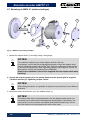
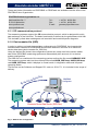
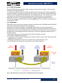
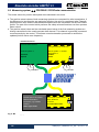
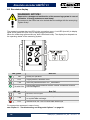
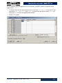
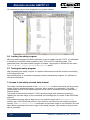
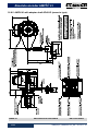
1
English
Operating and assembly instructions
Absolute encoder with
PROFIBUS-DP interface and PROFIsafe protocol
AMP 41 in construction types B5 (flange) and B35 (flange and foot)
AMPH 41 (hollow shaft design)
Functional safety according to EN 61508: SIL CL3 and EN ISO 13849: PL e
Read the operating and assembly instructions prior to
assembly, starting installation and handling!
Keep for future reference!
Translation of the original operating and assembly instructions
AMP(H)41_MANUAL-en_R6
ID 68749
Release date: 2014-11-14
Absolute encoder AMP(H) 41
Manufacturer / Publisher
Johannes Hübner
Phone:
Fabrik elektrischer Maschinen GmbH
Fax:
+49 641 73645
Siemensstr. 7
Internet:
www.huebner-giessen.com
35394 Giessen / Germany
E-mail:
[email protected]
Document information
Release date/Rev. date:
Document / Rev. No.:
File name:
Author:
Order no.:
2
+49 641 7969 0
2014-11-14
AMP(H)41_MANUAL-en_R6
AMP(H)41_MANUAL-en_R6.pdf
F. Sitt, J. Klingelhöfer, Me. Engels
ID 68749
AMP(H)41_MANUAL-en_R6 - 2014-11-14
Absolute encoder AMP(H) 41
Trademarks
PROFIBUS™, PROFINET™ and PROFIsafe™, as well as the relevant logos, are registered
trademarks of PROFIBUS Nutzerorganisation e.V. (PNO), SIMATIC is a registered trademark
of SIEMENS AG and Loctite® is a registered trademark of Henkel AG & Co. KG, Düsseldorf.
Brand names and product names are trademarks or registered trademarks of their respective
owner. Protected trademarks bearing a ™ or ® symbol are not always depicted as such in the
manual. However, the statutory rights of the respective owners remain unaffected.
Copyright
It is strictly forbidden to reproduce this publication or parts of this publication in any form or by
any means without the prior written permission of Johannes Hübner Fabrik elektrischer
Maschinen GmbH. Content information, text, drawings, graphics, and other representations are
protected by copyright and are subject to commercial property rights. Duplications of any kind
that are not combined with use of the machine are prohibited without manufacturer's written
consent. Actions to the contrary make damage compensation mandatory.
Copyright© Johannes Hübner Fabrik elektrischer Maschinen GmbH
Change reservation
The manual has been drawn up with the utmost care and attention. Nevertheless, we cannot
exclude the possibility of errors in form and content.
All rights, subject to errors and changes due to technical improvements reserved.
Font styles
Italic or bold font styles are used for the title of a document or are used for highlighting.
Courier-New font displays text, which is visible on the screen and software/software menu
selections.
AMP(H)41_MANUAL-en_R6 - 2014-11-14
3
Absolute encoder AMP(H) 41
Contents
Revision index .............................................................................................................................. 8
1 General Information.................................................................................................................. 9
1.1 Applicability ................................................................................................................................ 9
1.2 General functional description .................................................................................................... 9
1.2.1 Main Features ............................................................................................................. 10
1.2.2 Principle of the safety function..................................................................................... 10
1.3 Applied directives and standards .............................................................................................. 11
1.4 Overview of the complete system ............................................................................................. 13
2 Basic safety instructions ....................................................................................................... 14
2.1 Explanation of symbols and notes ............................................................................................ 14
2.2 General risks when using the product ....................................................................................... 15
2.3 Intended use ............................................................................................................................ 15
2.4 Non-intended use..................................................................................................................... 15
2.5 Safety functions of the fail-safe processing unit ........................................................................ 16
2.5.1 Mandatory safety checks / measures .......................................................................... 16
2.6 Warranty and liability ................................................................................................................ 17
2.7 Organizational measures ......................................................................................................... 17
2.8 Personnel selection and qualification; basic obligations ............................................................ 17
2.9 Safety information .................................................................................................................... 18
3 Transport, packaging and storage ....................................................................................... 19
3.1 Safety instructions for transport ................................................................................................ 19
3.2 Incomings goods inspection ..................................................................................................... 19
3.3 Packaging / disposal ................................................................................................................ 19
3.4 Storage of packages (devices) ................................................................................................. 19
4 Assembly ................................................................................................................................. 20
4.1 Safety instructions and requirements ........................................................................................ 20
4.2 Technical notes ........................................................................................................................ 21
4.3 Required tools.......................................................................................................................... 21
4.4 Mounting preparations ............................................................................................................. 21
4.5 Mounting of AMP 41, construction type B5 (flange) .................................................................. 22
4.6 Mounting of AMP 41, construction type B35 (flange and foot) ................................................... 23
4.7 Mounting of AMPH 41, (hollow shaft type) ................................................................................ 24
4.8 Dismantling of AMPH 41 .......................................................................................................... 25
5 Installation / Preparation for Commissioning ..................................................................... 26
5.1 Basic rules ............................................................................................................................... 26
5.2 PROFIBUS transfer technology, cable specification ................................................................. 27
5.3 Connection .............................................................................................................................. 28
5.3.1 Supply voltage ............................................................................................................ 28
5.3.2 PROFIBUS ................................................................................................................. 29
5.3.3 Incremental interface .................................................................................................. 29
5.3.4 Optional external SSI safety channel ........................................................................... 29
5.4 Bus termination ........................................................................................................................ 29
5.5 Bus addressing ........................................................................................................................ 30
5.6 Incremental interface................................................................................................................ 30
5.6.1 Signal characteristics of incremental interface ............................................................. 31
4
AMP(H)41_MANUAL-en_R6 - 2014-11-14
Absolute encoder AMP(H) 41
6 PROFIBUS / PROFIsafe – Commissioning .......................................................................... 31
6.1 PROFIBUS ............................................................................................................................... 31
6.1.1 DP communication protocol ......................................................................................... 32
6.1.2 Device master file (GSD) ............................................................................................. 32
6.1.3 PNO ID number ........................................................................................................... 33
6.2 PROFIsafe ............................................................................................................................... 33
6.3 Measuring system ßà PROFIBUS / PROFIsafe communication ............................................. 34
6.4 Start-up on PROFIBUS............................................................................................................. 35
6.5 Bus status display .................................................................................................................... 36
6.6 Configuration ............................................................................................................................ 37
6.6.1 Safety-oriented data, JHG-PROFIsafe module ............................................................ 37
6.6.2 Register structure of safety-oriented data .................................................................... 38
6.6.2.1 Input data ................................................................................................................. 38
6.6.2.1.1 Cam register .......................................................................................................... 38
6.6.2.1.2 Status .................................................................................................................... 38
6.6.2.1.3 Speed ................................................................................................................... 38
6.6.2.1.4 Multi-Turn / Single-Turn ......................................................................................... 39
6.6.2.1.5 Safe-Status ........................................................................................................... 39
6.6.2.2 Output data .............................................................................................................. 41
6.6.2.2.1 Control1 ................................................................................................................ 41
6.6.2.2.2 Control2 ................................................................................................................ 41
6.6.2.2.3 Preset Multi-Turn / Preset Single-Turn ................................................................... 41
6.6.2.2.4 Safe-Control .......................................................................................................... 42
6.6.3 Process data, JHG-PROFIBUS module ....................................................................... 43
6.6.4 Register structure of the process data ......................................................................... 43
6.6.4.1 Input data ................................................................................................................. 43
6.6.4.1.1 Cam register .......................................................................................................... 43
6.6.4.1.2 Speed ................................................................................................................... 43
6.6.4.1.3 Multi-Turn / Single-Turn ......................................................................................... 44
6.7 Parameterization ...................................................................................................................... 44
6.7.1 F-Parameters (F_Par) ................................................................................................. 45
6.7.1.1 F_Check_SeqNr ....................................................................................................... 45
6.7.1.2 F_SIL ....................................................................................................................... 45
6.7.1.3 F_CRC_Length ........................................................................................................ 45
6.7.1.4 F_Block_ID .............................................................................................................. 46
6.7.1.5 F_Par_Version ......................................................................................................... 46
6.7.1.6 F_Source_Add / F_Dest_Add ................................................................................... 46
6.7.1.7 F_WD_Time ............................................................................................................. 46
6.7.1.8 F_iPar_CRC ............................................................................................................. 46
6.7.1.9 F_Par_CRC.............................................................................................................. 47
6.7.2 iParameters (F_iPar) ................................................................................................... 47
6.7.2.1 Integration time Safe ................................................................................................ 48
6.7.2.2 Integration time Unsafe............................................................................................. 48
6.7.2.3 Window increments .................................................................................................. 48
6.7.2.4 Idleness tolerance Preset ......................................................................................... 48
6.7.2.5 Direction ................................................................................................................... 48
7 Parameter Definition/CRC Calculation ................................................................................. 49
7.1 iParameters .............................................................................................................................. 49
7.1.1 CRC calculation across the iParameters ...................................................................... 49
7.2 F-Parameters ........................................................................................................................... 51
7.2.1 Non-settable F-Parameters ......................................................................................... 51
7.2.2 Settable F-Parameters ................................................................................................ 51
AMP(H)41_MANUAL-en_R6 - 2014-11-14
5
Absolute encoder AMP(H) 41
8 Safety Creation – Configuration Example ........................................................................... 52
8.1 Prerequisites ............................................................................................................................ 53
8.2 Hardware configuration ............................................................................................................ 54
8.2.1 Defining the properties of the hardware configuration .................................................. 59
8.3 Parameterization ...................................................................................................................... 64
8.3.1 Setting the iParameters............................................................................................... 64
8.3.2 Setting the F-Parameters ............................................................................................ 65
8.4 Creating the missing (F-)blocks ................................................................................................ 66
8.4.1 Program structure ....................................................................................................... 66
8.4.2 F-Runtime Group ........................................................................................................ 66
8.4.3 Generating the Object Blocks (OBs)............................................................................ 67
8.4.4 Generating the functions (F-FCs) ................................................................................ 68
8.4.5 Programming the F-Blocks .......................................................................................... 69
8.5 Generating the safety program ................................................................................................. 71
8.6 Loading the safety program ...................................................................................................... 72
8.7 Testing the safety program ....................................................................................................... 72
9 Access to the safety-oriented data channel ....................................................................... 72
9.1 Output of passivated data (substitute values) in case of error ................................................... 73
9.2 F-Periphery-DB ........................................................................................................................ 73
9.2.1 Measuring system F-Periphery-DB “DB1638” – Overview of variables ......................... 74
9.2.1.1 PASS_ON................................................................................................................ 74
9.2.1.2 ACK_NEC................................................................................................................ 74
9.2.1.3 ACK_REI ................................................................................................................. 75
9.2.1.4 IPAR_EN ................................................................................................................. 75
9.2.1.5 PASS_OUT/QBAD/QBAD_I_xx/QBAD_O_xx ........................................................... 75
9.2.1.6 ACK_REQ ............................................................................................................... 75
9.2.1.7 IPAR_OK ................................................................................................................. 76
9.2.1.8 DIAG ....................................................................................................................... 76
9.3 Access to variables of the F-Perhiphery-DB ............................................................................. 76
9.4 Passivation and Operator acknowledgment of the measuring system ....................................... 77
9.4.1 After start-up of the F-System ..................................................................................... 77
9.4.2 After communication errors ......................................................................................... 77
10 Preset Adjustment Function ............................................................................................... 78
10.1 Procedure .............................................................................................................................. 79
11 Troubleshooting and Diagnosis Options .......................................................................... 80
11.1 Optical displays ...................................................................................................................... 80
11.1.1 LED, green ............................................................................................................... 80
11.1.2 LED, red ................................................................................................................... 81
11.2 Use of the PROFIBUS diagnosis ............................................................................................ 82
11.2.1 Standard diagnosis ................................................................................................... 82
11.2.1.1 Station status 1 ...................................................................................................... 83
11.2.1.2 Station status 2 ...................................................................................................... 83
11.2.1.3 Station status 3 ...................................................................................................... 83
11.2.1.4 Master address ...................................................................................................... 83
11.2.1.5 Manufacturer’s identifier ......................................................................................... 84
11.2.1.6 Length (in bytes) of the extended diagnosis ............................................................ 84
11.2.2 Extended diagnosis ................................................................................................... 84
6
AMP(H)41_MANUAL-en_R6 - 2014-11-14
Absolute encoder AMP(H) 41
12 Replacing the Measuring System ....................................................................................... 85
13 Checklist.................................................................................................................................86
14 Technical Data ....................................................................................................................... 87
14.1 Safety ..................................................................................................................................... 87
14.2 Electrical characteristics ......................................................................................................... 87
14.2.1 General ..................................................................................................................... 87
14.2.2 Device-specific .......................................................................................................... 88
14.3 Environmental conditions ........................................................................................................ 89
14.4 Mechanical characteristics ...................................................................................................... 89
14.4.1 AMP 41 ..................................................................................................................... 89
14.4.2 AMPH 41................................................................................................................... 90
15 Maintenance ...........................................................................................................................91
16 Appendix ................................................................................................................................92
16.1 References ............................................................................................................................. 92
16.2 Abbreviations and terms used................................................................................................. 92
16.3 TÜV certificate ........................................................................................................................ 94
16.4 PROFIBUS-DP certificate ....................................................................................................... 95
16.5 PROFIsafe certificate.............................................................................................................. 96
16.6 EC Declaration of Conformity.................................................................................................. 97
16.7 Accessories ............................................................................................................................ 99
16.8 Dimension drawings ............................................................................................................. 100
16.8.1 AMP 41, construction type B5 (flange) ..................................................................... 100
16.8.2 AMP 41 construction type B35 (flange and foot) ...................................................... 101
16.8.3 AMPH 41 (hollow shaft design) ................................................................................ 102
16.8.4 AMPH 41 with adapter shaft ADA HFA (external centering) ..................................... 103
16.8.5 AMPH 41 with adapter shaft ADA HG (screw-in type) .............................................. 104
16.9 Type plate ............................................................................................................................ 105
16.10 Type code .......................................................................................................................... 106
AMP(H)41_MANUAL-en_R6 - 2014-11-14
7
Absolute encoder AMP(H) 41
Revision index
Revision
8
Date
Releaser
1
First release
Change
2014-02-19
J. Klingelh.
2
Photo added
2014-03-03
Me. Engels
5
Alignment of revision no. with German version
Certificates added
Dimension drawing HM 13 M 104957 à
HM 13 M 104957 a
Mounting instructions added
Accessories added
2014-09-24
J. Klingelh.
6
Chapter 15 Maintenance added
2014-11-14
J. Klingelh.
AMP(H)41_MANUAL-en_R6 - 2014-11-14
Absolute encoder AMP(H) 41
1 General Information
These operating and assembly instructions contain the following topics:
● General functional description
● Basic safety instructions with declaration of the intended use
● Characteristics
● Assembly
● Installation/Commissioning
● Parameterization
● Error causes and remedies
The operating and assembly instructions are supplementary to other documentation, such as
product data sheets, dimension drawings, etc.
The scope of delivery includes the absolute encoder AMP(H) 41, the operating and assembly
instructions and the Software and Support CD.
The operating and assembly instructions may be requested separately.
1.1 Applicability
These operating and assembly instructions apply exclusively for the following measuring
system series with PROFIBUS-DP interface and PROFIsafe profile:
● AMP 41
● AMPH 41
The products are labelled with affixed nameplates and are components of a system.
The following documentation therefore also applies:
● operator’s operating instructions specific to the system,
● and these operating and assembly instructions
1.2 General functional description
The AMP(H) 41 rotary measuring system is a safe and absolute Multi-Turn position measuring
system with PROFIBUS interface and PROFIsafe protocol.
The measuring system has primarily been designed for use in systems that require safe
position detection.
The safety measuring system consists of a redundant, two-channel system, in which optical
and magnetic scanning units are arranged on a drive shaft, designed as a hollow shaft or
solid shaft.
AMP(H)41_MANUAL-en_R6 - 2014-11-14
9
Absolute encoder AMP(H) 41
1.2.1 Main Features
PROFIBUS interface with PROFIsafe protocol, for transfer of a safe position and speed
Quick process data channel via PROFIBUS, not safety-oriented
Additional incremental interface, not safety-oriented
Two-channel scanning system, for generation of safe measured data through internal
channel comparison
– Channel 1, master system:
optical Single-Turn scanning via code disk with transmitted light and magnetic Multi-Turn
scanning
– Channel 2, inspection system:
magnetic Single and Multi-Turn scanning
● A common drive shaft
●
●
●
●
Due to its technology the optical system possesses greater accuracy; therefore it is used as
master system. The data of the master system are unevaluated in the non-safety-oriented
process data channel with normal PROFIBUS protocol, but are made available with a short
cycle time.
The magnetic scanning system serves for the internal safety check. The "safe data" obtained
through two-channel data comparison are packed into the PROFIsafe protocol and also
transmitted to the control via the PROFIBUS.
The incremental interface is derived from the master system and is not evaluated in relation to
safety.
1.2.2 Principle of the safety function
System safety results when:
– Each of the two scanning channels is largely fail-safe thanks to individual diagnostic
measures.
– The measuring system internally compares the positions detected by both channels in two
channels, also determines the speed in two channels and transfers the safe data to the
PROFIBUS in the PROFIsafe protocol, see Fig. 1: System diagram “Black Channel” on
page 13.
– In the event of a failed channel comparison or other errors detected through internal
diagnostic mechanisms, the measuring system switches the PROFIsafe channel into error
state.
– The measuring system initialization and execution of the preset adjustment function are
appropriately verified.
– The control additionally checks whether the obtained position data lie in the position window
expected by the control. Unexpected position data are e.g. position jumps, tracking error
deviations and incorrect direction of travel.
– When errors are detected the control introduces appropriate safety measures defined by the
system manufacturer.
– The system manufacturer ensures, through correct mounting of the measuring system, that
the measuring system is always driven by the axis for measurement and is not overloaded.
– The system manufacturer performs a verified test during commissioning and in the event of
any parameter modification.
10
AMP(H)41_MANUAL-en_R6 - 2014-11-14
Absolute encoder AMP(H) 41
1.3 Applied directives and standards
The measuring systems in series AMP(H) 41 have been developed, designed and tested
taking account of the applicable European and international standards, directives and
requirements.
Directives
2004/108/EC
EMC Directive
2006/42/EC
Machinery Directive
EN 61000-6-2:2005/AC:2005; EMC; Immunity to disturbance, industrial environments:
EN 61000-4-2:2009
Electrostatic discharge, ESD
EN 61000-4-3:2006 + A1:2008
+ A2:2010
Radio-frequency electromagnetic fields
EN 61000-4-4:2012
Fast transient electrical disturbances, burst
EN 61000-4-5:2006
Surge
EN 61000-4-6:2009
Immunity to conducted disturbances,
induced by radio-frequency fields
EN 61000-4-8:2010
Power frequency magnetic fields
EN 61326-3-2:2008
Immunity to disturbance requirements for safety-related systems
and for devices
EN 62061:2005/AC:2010,
Appendix E
Electromagnetic phenomena and increased levels of immunity to
disturbance for SRECS, which are intended for use in industrial
environments in accordance with IEC61000-6-2
EN 61000-6-3:2007/A1:2011/AC:2012; EMC; Transient emissions, residential environments:
EN 55011:2009 + A1:2010
Disturbance field strength, 30 MHz - 1 GHz
Interference voltage, < 30 MHz
AMP(H)41_MANUAL-en_R6 - 2014-11-14
11
Absolute encoder AMP(H) 41
Safety
EN 61508-1-7:2010
Functional safety
EN 61800-5-2:2007
Adjustable speed electrical power drive systems; Safety
requirements - Functional
EN 60204-1:2006
Safety of machinery - Electrical equipment of machines - Part 1:
General requirements
EN 62061:2005/AC:2010,
Appendix F
Safety of machinery - Functional safety of safety-related E/E/PE
control systems
EN ISO 13849-1:2008/AC:2009
Safety of machinery - Safety-related parts of control systems
Types of construction
EN 60034-7:1993 + A1:2001
Rotating electrical machines - Part 7: Classification of types of
construction, mounting arrangements and terminal box position
(IM code)
Environmental influences
EN 60068-1:1994
Environmental testing. General and guidance
EN 60068-2-1:2007
Cold
EN 60068-2-2:2007
Dry heat
EN 60068-2-6:2008
Vibration (sinusoidal)
EN 60068-2-14:2009
Change of temperature
EN 60068-2-27:2009
Single shock
EN 60068-2-47:2005
Environmental testing - Part 2-47: Tests - Mounting of specimens
for vibration, impact and similar dynamic tests
EN 60068-2-64:2008
Broadband random
EN 60529:1991 + A1:2000
Specification for degrees of protection provided by enclosures
(IP code)
Certification of bus systems
GS - ET- 26
12
Final draft by Electrotechnical Expert Committee for the
inspection and certification of: "Bus systems for the transmission
of safety-relevant messages"
AMP(H)41_MANUAL-en_R6 - 2014-11-14
Absolute encoder AMP(H) 41
1.4 Overview of the complete system
Fig. 1: System diagram
A Master system, Single-Turn
● Optical detection of number of steps/revolution
● Max. 8192 steps/revolution with 13 bit accuracy
● Incremental signals for position feedback, 4096 steps/revolution
B Master system, Multi-Turn
● Magnetic detection of the number of revolutions
● Max. 32768 revolutions
C Inspection system, Single-Turn
● Magnetic detection of number of steps/revolution
● Max. 8192 steps/revolution with 8 bit accuracy
D Inspection system, Multi-Turn
● Magnetic detection of the number of revolutions
● Max. 32768 revolutions
E Channel comparison, speed generation and bus handling
● Position comparison of the master in the parameterized position window of the test channel
● Generation of speed depending on the parameterized integration time
● Generation of PROFIBUS-DP and PROFIsafe telegrams
AMP(H)41_MANUAL-en_R6 - 2014-11-14
13
Absolute encoder AMP(H) 41
2 Basic safety instructions
2.1 Explanation of symbols and notes
Warnings are indicated by symbols in these operating and assembly instructions. The warnings
are introduced by signal words that express the scope of the hazard.
The warnings must be strictly heeded; you must act prudently to prevent accidents, personal
injury, and property damage.
DANGER!
Means that death or serious injury will occur if the required precautions are not
met.
WARNING!
Means that death or serious injury can occur if the required precautions are not
met.
CAUTION!
Means that minor injuries can occur if the required precautions are not met.
NOTICE!
Indicates a possibly dangerous situation that can result in material damage if it
is not avoided.
NOTES!
Indicates important information or features and application tips for the product
used.
NOTES!
Means that appropriate ESD-protective measures are to be considered
according to EN 61340-5-1 supplementary sheet 1.
NOTES!
Do not use a hammer or similar tool when installing the device due to the risk of
damage occurring to the bearings or coupling!
14
AMP(H)41_MANUAL-en_R6 - 2014-11-14
Absolute encoder AMP(H) 41
2.2 General risks when using the product
The product, hereinafter referred to as the measuring system, is manufactured according to
state-of-the-art technology and accepted safety rules. Nevertheless, non-intended use can
pose a danger to life and limb of the user or third parties, or lead to impairment of the
measuring system or other property!
Only use the measuring system in perfect technical condition, and only for its intended use,
paying attention to safety and dangers, and in compliance with the operating and assembly
instructions! Faults which could threaten safety should be eliminated without delay!
2.3 Intended use
The safety measuring system can be used for the detection of angular movement and
processing of measured data for a downstream safety host (F-Host) in systems in which the
goal of "Protection of travel" must be safely achieved. The complete processing chain of the
safety function must then satisfy the requirements of the applied safety standard.
The safety measuring system must only be used in safety applications in conjunction with a
control certified according to the applied safety standard.
The system manufacturer must check that the characteristics of the measuring system satisfy
his application-specific safety requirements. The responsibility or decision regarding the use of
the measuring system lies with the system manufacturer.
Intended use also includes:
● observing all instructions in this operating and assembly instructions,
● observing the nameplate and any prohibition or instruction symbols on the measuring
system,
● observing the operating instructions from the machine/system manufacturer,
● operating the measuring system within the limit values specified in the technical data,
● ensuring that the fail-safe processing unit (F-Host) fulfils all required safety functions,
● observing and using the checklist in the Appendix,
● safe mounting (form-closed) of the measuring system to the driving axis.
2.4 Non-intended use
WARNING! NOTICE!
Danger of death, physical injury and damage to property in case of nonintended use of the measuring system!
The following areas of use are especially forbidden:
– in environments where there is an explosive atmosphere
– for medical purposes
– fastening transport or lifting tackle to the device,
for example a crane hook to lift a motor
– fastening packaging components to the device,
for example ratchet straps, tarpaulins etc.
– using the device as a step,
for example by people to climb onto a motor
AMP(H)41_MANUAL-en_R6 - 2014-11-14
15
Absolute encoder AMP(H) 41
2.5 Safety functions of the fail-safe processing unit
The F-Host, to which the measuring system is connected, must perform the following safety
checks.
NOTES!
To enable the correct measures to be taken in the case of an error, the
following applies:
If no safe position can be output due to an error detected by the measuring
system, the PROFIsafe data channel is automatically put into fail-safe status. In
this status so-called "passivated data" are output via PROFIsafe.
See chapter 9.1 "Output of passivated data (substitute values) in case of
error" on page 73.
Passivated data outputs are:
– PROFIsafe data channel: all are set to 0
– PROFIsafe status:
error bit 21 Device_Fault is set
– PROFIsafe-CRC:
valid
Upon receipt of passivated data, the F-Host must put the system into a
safe state. It is only possible to leave this error state by eliminating the
error and then switching the supply voltage off and on again!
The process data channel addressable via PROFIBUS is not necessarily
affected by this. If the internal diagnosis in the master channel does not detect
an error, the process data are still output. However, these data are not safe for
the purposes of a safety standard.
2.5.1 Mandatory safety checks / measures
Measures for commissioning, changes
F-Host error reaction
Application-dependent parameterization and definition of the
necessary iParameters, see chapter 7.1 “iParameter”
on page 49.
–
In the event of parameter changes, check that the measure is
executed as desired.
STOP
Check by F-Host
F-Host error reaction
Cyclical consistency check of the current safety-oriented data
from the JHG-PROFIsafe module in relation to the previous
data.
STOP
Travel curve calculation and monitoring by means of cyclical
data from the JHG-PROFIsafe module.
STOP
Monitoring of cyclical data from the
JHG-PROFIsafe module, and the process data from the
JHG-PROFIsafe module.
Receipt of passivated
data à STOP
Timeout: Monitoring of the measuring system - response time.
For checking e.g. cable breakage, power failure etc.
STOP
16
AMP(H)41_MANUAL-en_R6 - 2014-11-14
Absolute encoder AMP(H) 41
2.6 Warranty and liability
In principle the "General Terms and Conditions" of Johannes Hübner - Fabrik elektrischer
Maschinen GmbH apply. These are available to the operator with the Order Confirmation or
when the contract is concluded at the latest. Warranty and liability claims in the case of
personal injury or damage to property are excluded if they result from one or more of the
following causes:
● Non-intended use of the measuring system
● Improper assembly, installation, start-up and programming of the measuring system
● Work carried out incorrectly on the measuring system
● Operation of the measuring system with technical defects
● Mechanical or electrical modifications to the measuring systems undertaken autonomously
● Repairs carried out autonomously
● Third party interference and Acts of God
● Non-observance of these operating and assembly instructions
● Opening of the measuring system
● Deployment of non-qualified personnel
2.7 Organizational measures
● The operating and assembly instructions must always be kept ready-to-hand at the place of
use of the measuring system.
● In addition to the operating and assembly instructions, generally valid legal and other binding
regulations on accident prevention and environmental protection must be observed and
communicated.
● The respective applicable national, local and system-specific provisions and requirements
must be observed and communicated.
● The operator is obliged to inform personnel on special operating features and requirements.
● Prior to commencing work, personnel working with the measuring system must have read
and understood the chapter 2 "Basic safety instructions" on page 14.
● The nameplate and any prohibition or instruction symbols applied on the measuring system
must always be maintained in a legible state.
● Do not undertake any mechanical or electrical modifications to the measuring system, except
for those expressly described in this operating and assembly instructions.
● Repairs may only be undertaken by the manufacturer or a center or person authorized by the
manufacturer.
2.8 Personnel selection and qualification; basic obligations
● All work on the measuring system must only be carried out by qualified personnel.
Qualified personnel includes persons, who, through their training, experience and instruction,
as well as their knowledge of the relevant standards, provisions, accident prevention
regulations and operating conditions, have been authorized by the persons responsible for
the system to carry out the required work and are able to recognize and avoid potential
hazards. They are capable of identifying and avoiding potential hazards.
● The definition of “qualified personnel” also includes an understanding of the standards VDE
0105-100 and IEC 364 (source: e.g. Beuth Verlag GmbH, VDE-Verlag GmbH).
● The responsibility for assembly, installation, commissioning and operation must be clearly
defined. The obligation exists to provide supervision for trainee personnel.
AMP(H)41_MANUAL-en_R6 - 2014-11-14
17
Absolute encoder AMP(H) 41
2.9 Safety information
WARNING! NOTICE! NOTES!
Destruction, damage and malfunction of the measuring system!
– Only carry out wiring work or opening and closing of electrical connections
with the system de-energized.
– Do not undertake any welding work if the measuring system is already wired
or switched on.
– Falling below or exceeding the permissible operating temperature limit values
must be prevented through an appropriate heating/cooling measure at the
place of installation.
– The measuring system must be installed so that no direct moisture can affect
the measuring system.
– Suitable aeration/ventilation and heating/cooling measures must be provided
at the place of installation to prevent the temperature falling below the dew
point (condensation).
– If an overvoltage of >36 V DC is inadvertently applied the measuring system
must be inspected in the factory of Johannes Hübner - Fabrik elektrischer
Maschinen GmbH, with specification of the reasons or circumstances.
– Potential hazards resulting from interactions with other systems and equipment which are or will be installed in the vicinity must be checked. The user is
responsible for taking appropriate measures.
– The power supply must be protected with a fuse suitable for the supply lead
cross-section.
– Cables used must be suitable for the temperature range.
– A defective measuring system must not be operated.
– Make sure that the installation environment is protected from aggressive
media (acids etc.).
– Avoid shocks (e.g. hammer blows) to the shaft during installation.
– Opening the measuring system is forbidden.
– Make sure that the access to the address switches and LEDs is locked after
the settings with the screw plug. Tighten firmly!
– The type plate specifies the technical characteristics of the measuring system.
If the type plate is no longer legible or if the type plate is completely missing,
the measuring system must not be operated.
– In case of storage as well as in the operation of the measuring system unused
connecting plugs have to be provided either with a mating connector or with a
protective cap. The IP protection class is to be selected according to the requirements.
NOTES!
The measuring system contains components and assemblies susceptible
to electrical discharge, which can be destroyed if incorrectly handled.
– Touching the measuring system connection contacts with the fingers must be
avoided or the relevant ESD protective measures must be applied.
NOTES!
Disposal
– If disposal has to be undertaken after the lifespan of the device, the respective applicable country-specific regulations are to be observed.
18
AMP(H)41_MANUAL-en_R6 - 2014-11-14
Absolute encoder AMP(H) 41
3 Transport, packaging and storage
NOTES!
Shipping information
– Do not drop the device or subject it to heavy impacts!
The device contains an optical system.
– Use only the original packaging.
Inappropriate packaging material may cause damage to the unit in transit.
– Storage temperature: -30 °C...+60 °C
– Store in a dry place.
3.1 Safety instructions for transport
NOTICE!
Material damage caused by improper transport!
Observe the symbols and information on the packaging:
– Do not throw – risk of breakage
– Keep dry
– Do not expose to heat above 40°C or direct sunlight.
3.2 Incomings goods inspection
Check delivery immediately upon receipt for completeness and possible transport damage.
Inform the forwarder directly on receipt of the goods about existing transport damages (prepare
pictures for evidence).
3.3 Packaging / disposal
The packaging is not taken back and must be disposed of in accordance with the respective
statutory regulations and local guidelines.
3.4 Storage of packages (devices)
Keep dry
Keep packages dry and free from dust; protect from moisture
Protect against heat
Protect packages from heat above 40° C and direct sunlight
If you intend to store the device for a longer period of time (> 6 months) we recommend you
use protective packaging (with desiccant).
NOTES!
Turn the shaft of the device every 6 month to prevent the bearing grease
solidifying!
AMP(H)41_MANUAL-en_R6 - 2014-11-14
19
Absolute encoder AMP(H) 41
4 Assembly
4.1 Safety instructions and requirements
WARNING!
At assembly, dismantling and other work to the device the basic safety
instructions to chapter 2 must be observed.
The assembly and dismantling of the measuring system must only be carried
out by qualified personnel!
DANGER! NOTICE!
Danger of death, serious physical injury and/or damage to property due to
deactivation of safety functions, caused by an unstable shaft drive!
● The system manufacturer must implement suitable design measures, so that
the drive of the measuring system is ensured at all times through the shaft
and mounting of the measuring system (fault exclusion). The specifications of
DIN EN 61800-5-2:2008 "Adjustable speed electrical power drive systems,
Safety requirements - Functional, Table D.16 – Motion and position sensors"
must be observed.
● In general, the requirements and acceptance conditions for the complete
system must be taken into account for mounting.
● The measuring system must be inspected on a regular basis (see below).
Inspections must be recorded in a log book.
As the installation situation is application-dependent, the following notes
are not exhaustive.
● All fastening screws must be secured against unintentional loosening.
All screwed connections must be inspected once a year.
● In case of applications with low operating temperatures, increased values for
the start-up torque result. This fact is to be considered when the assembling
and wave drive is performed.
● After approx. 16 000 - 20 000 hours of operation or higher levels of
continuous load:
Check deep groove ball bearings for noise, running smoothly. Bearings must
be replaced by the manufacturer only.
AMP 41 (solid shaft type):
● A suitable coupling with positive connection must be used for the application.
● Inspect the coupling for damage and ensure it is free of play once a year.
● The coupling manufacturer's information and installation requirements must
be observed.
In particular, you must ensure that:
– the coupling is suitable for the specified speed and the potential parallel,
angular and axial offset,
– installation is on a grease-free shaft,
– the coupling and the measuring system are not radially and axially loaded,
– the clamping screws are tightened with the torque defined by the coupling
manufacturer and are secured against unintentional loosening, so that the
coupling cannot slip on the drive shaft or on the measuring system shaft.
20
AMP(H)41_MANUAL-en_R6 - 2014-11-14
Absolute encoder AMP(H) 41
DANGER! NOTICE!
Danger of death, serious physical injury and/or damage to property due to
deactivation of safety functions, caused by an unstable shaft drive!
AMPH 41 (hollow shaft type):
● The measuring system must be installed on a grease-free shaft by means of
form-closure, using a parallel key / groove combination.
● Axial slipping of the measuring system on the drive shaft must be prevented
through fixing by means of the axial tensioning disc.
● The torque bracket must be inspected once a year:
check link heads can move freely. You must be able to move the link rod
manually. If it proves difficult to move, lightly oil the link rod heads or apply
lubricant spray.
4.2 Technical notes
NOTES!
Do not use a hammer or similar tool when installing the device due to the risk of
damage occurring to the bearings or coupling!
Ambient temperature
The max. permissible ambient temperature depends on the speed and degree of protection of
the device and the place of installation.
Degree of protection
The device complies with the specified degree of protection (see chapter 14.3 “Environmental
conditions” on page 89) only with screwed-on mating connectors or blind plugs!
Deep groove ball bearings
Absolute encoders AMP(H) 41 are fitted with maintenance-free, greased "for-life" deep groove
bearings. Bearings must be changed by the manufacturer only.
Opening the encoder renders the guarantee null and void.
Screw retention
All fastening screws must be secured against unintentional loosening. We recommend using
Loctite® 243 thread locker (medium strength).
4.3 Required tools
● Spanners: 10 mm, 13 mm, 14 mm, 24 mm, Allen key: 5 mm
● Flat-blade screwdriver, assembly grease, Loctite® 243 (medium strength thread locker)
4.4 Mounting preparations
● Ensure all accessories are available.
NOTES!
Fastening screws and earth cable are not included in the scope of delivery.
● Preparing the place of attachment: Clean the (motor) shaft, centering, bolting surfaces and
fastening threads; check for damage. Repair any damage!
AMP(H)41_MANUAL-en_R6 - 2014-11-14
21
Absolute encoder AMP(H) 41
4.5 Mounting of AMP 41, construction type B5 (flange)
1
1a
2
3
6
4
3a
5
8
7
Fig. 2: AMP 41, construction type B5 (mounting example)
DANGER! NOTICE!
Danger of death, serious physical injury and/or damage to property due to
deactivation of safety functions, caused by an unstable mounting!
It is the responsibility of the user to ensure the screwed connections used to
secure the encoder are properly dimensioned and that the mounting process is
carried out in accordance with best practices.
Ensure the centering is implemented to tolerance Ø85 H7 (0 / +0.035).
1. Fit coupling (2) onto (motor) shaft (1).
2. Secure the coupling hub on the (motor) shaft (1) using the clamping screw.
3. Lightly grease the (motor) centering (1a).
4. Fasten the intermediate flange (3) to the motor using the fastening screws (4).
5. Lightly grease the intermediate flange centering (3a).
6. Fit the encoder (7) into both the centering (3a) and coupling hub (2) at the same time.
7. Secure the encoder (7) to the intermediate flange (3) using at least 4 M6 screws (8) of
the property class 8.8 and washers to ISO 7090 - 6 - 200 HV distributed evenly around
the circumference!
8. Secure the coupling hub (2) on the encoder shaft using the clamping screw.
9. Screw in the sealing plug (5) to seal the access bore to the coupling.
22
AMP(H)41_MANUAL-en_R6 - 2014-11-14
Absolute encoder AMP(H) 41
4.6 Mounting of AMP 41, construction type B35 (flange and foot)
1
2
B5
3
4
5
B3
Fig. 3: AMP 41, construction type B35 (mounting example)
DANGER! NOTICE!
Danger of death, serious physical injury and/or damage to property due to
deactivation of safety functions, caused by an unstable mounting!
It is the responsibility of the user to ensure the screwed connections used to
secure the encoder are properly dimensioned and that the mounting process is
carried out in accordance with best practices.
Ensure the housing foot is mounted on a plane, dry, meaning free from oil,
mounting surface.
If shock loads > 30 g arise in the application, we recommend using screws of
the property class 10.9 as well as friction-enhancing shims in the parting line,
see Chapter 16.7 ”Accessories“.
1. Fit coupling (2) onto (motor) shaft (1).
2. Secure the coupling hub on the (motor) shaft (1) using the clamping screw.
3. Align the encoder shaft (3) to the (motor) shaft (1) and insert into the coupling hub (2).
Angle misalignment and parallel displacement between the (motor) shaft and the encoder
shaft are mounting errors and should be kept as small as possible.
Mounting errors cause radial forces to act on the encoder shaft, reduce the service life of
the bearings and the coupling and degrade the quality of the signals (harmonic content).
4. Secure the encoder foot (B3) to the bracket (5) using 4 hexagon head screws M6 (4)
and the 4 supplied washers Ø18/6.4 x 1.6!
5. Secure the coupling hub on the encoder shaft using the clamping screw.
AMP(H)41_MANUAL-en_R6 - 2014-11-14
23
Absolute encoder AMP(H) 41
4.7 Mounting of AMPH 41, (hollow shaft type)
1
3
2
7
5
9
6
4
10
8
Fig. 4: AMPH 41 (mounting example)
1. Mount the adapter shaft (1) and align using a dial gauge.
NOTES!
The maximum radial run-out of the adapter shaft is 0.05 mm.
If necessary, use the ball thrust adjustment screws to align the adapter shaft.
Secure ball thrust screws with Loctite ® 243. Remove unused ball thrust screws
or secure with Loctite® 243. Max. tightening torque for M12 approx. 25 Nm, for
M16 approx. 35 Nm. Use parallel keys to DIN 6885.
Observe the installation instructions supplied with the adapter shaft when
installing!
2. Secure the torque bracket (2) to the hollow shaft encoder (4) using the 4 supplied
Tensilock screws (3)! Tightening torque: 16 Nm
NOTES!
When fitting the device, it is possible to align the torque bracket in four different
directions.
3. Mount the hollow shaft device (4) to the adapter shaft (1).
NOTES!
The hollow shaft device must slide easily onto the adapter shaft. Never use
excessive force; otherwise the bearings may be damaged. If necessary, use
emery cloth or a file to rework the adapter shaft and the feather key. Do not
allow the device to hit hard against the collar of the shaft.
24
AMP(H)41_MANUAL-en_R6 - 2014-11-14
Absolute encoder AMP(H) 41
4. Secure the hollow-shaft device with the aid of the supplied axial tensioning disc (5)
and the hexagon socket head cap screw (6) (property class: 8.8)!
Tightening torque: 5.4 Nm.
NOTES!
The axial tensioning disc is supplied with several hexagon head socket cap
screws of different lengths. To select the suitable hexagon head socket cap
screw, see the dimensioning drawing HM 13 M 104960 on page 102.
The hexagon head socket cap screws are coated with a microencapsulated
adhesive as locking agent.
5. Fit the cover (7) and secure with 4 screws (8) to seal the hollow-shaft encoder.
6. Fastening the torque bracket:
Fastening without base plate:
Secure the link rod head of the link rod (9) to a fixed point (for example on the motor housing).
Fastening with base plate:
Secure the base plate (10) to a fixed point with two hexagon head screws (for example on the
motor housing or the foundations).
NOTES!
Once fitted the link rod must rotate easily around the link rod heads! Failure to
observe this point may result in damage to the bearings!
The perfect angle from the torque bracket (2) to the link rod (9) should be 90°.
The link heads are maintenance free. However, ensure they remain free from
soiling and paint!
4.8 Dismantling of AMPH 41
WARNING!
At assembly, dismantling and other work to the device the basic safety
instructions to chapter 2 must be observed.
The assembly and dismantling of the measuring system must only be
carried out by qualified personnel!
NOTES!
To dismantle the hollow-shaft encoder, use the draw-off-tool D-53663-Ia (available
as an accessory) if you are unable to remove the device manually from the
adapter shaft, after having removed the axial tensioning disc!
Draw-off-tool D-53663-Ia
Using the draw-off-tool, which is screwed into the withdrawal thread M25x0.75 of
the hollow shaft, allows you to remove the hollow-shaft encoder from the adapter
shaft without risking damage to the bearings.
AMP(H)41_MANUAL-en_R6 - 2014-11-14
25
Absolute encoder AMP(H) 41
5 Installation / Preparation for Commissioning
5.1 Basic rules
WARNING!
Deactivation of the safety function through conducted interference
sources!
– All nodes of the safety-relevant communication must be certified according to
IEC 61010 or must have a corresponding EC conformity declaration.
– All PROFIsafe devices used on the bus must have a PROFIBUS and a
PROFIsafe - certificate.
– All safety devices must also have a certificate from a "Notified Body" (e.g.
TÜV, BIA, HSE, INRS, UL, etc.).
– The 24V power supplies used must not cut out in the event of a fault in the
energy supply (safe under single fault conditions) and must fulfil SELV/PELV.
– No stubs lines.
– The shielding effect of cables must also be guaranteed after installation (bending radii/tensile strength!) and after connector changes. In cases of doubt, use
more flexible cables with a higher current carrying capacity.
– Only use M12 connectors for connecting the measuring system, which guarantee good contact between the cable shield and connector housing. The cable shield must be connected to the connector housing over a large area.
– A 5-wire cable with a PE-conductor isolated from the N-conductor (so-called
TN network) must be used for the drive/motor cabling. This will largely prevent
equipotential bonding currents and the development of interference.
– A shielded and stranded data cable must be used to ensure high electromagnetic interference stability of the system. The shielding should be connected
with low resistance to protective ground using large shield clips at both ends.
The shielding should be grounded in the switch cabinet only if the machine
ground is heavily contaminated with interference towards the switch cabinet
ground.
– Equipotential bonding measures must be provided for the complete processing chain of the system.
– Power and signal cables must be laid separately. During installation, observe
the applicable national safety and installation regulations for data and power
cables.
– Observe the manufacturer's instructions for the installation of converters and
for shielding power cables between frequency converter and motor.
– Ensure adequate dimensioning of the energy supply.
Upon completion of installation, a visual inspection with report should be carried out. Wherever
possible, the quality of the network should be verified using a suitable bus analysis tool:
no duplicate bus addresses, no reflections, no telegram repetitions etc.
26
AMP(H)41_MANUAL-en_R6 - 2014-11-14
Absolute encoder AMP(H) 41
NOTES!
To ensure safe and fault-free operation, the
– PROFIBUS Planning Guideline, PNO Order no.: 8.012,
– PROFIBUS Assembly Guideline, PNO Order no.: 8.022,
– PROFIBUS Commissioning Guideline, PNO Order no.: 8.032,
– PROFIsafe „Environmental Requirements“, PNO Order no.: 2.232,
– and the referenced Standards and PNO Documents contained in it must be
observed!
In particular the EMC directive in its valid version must be observed!
5.2 PROFIBUS transfer technology, cable specification
All devices are connected in a bus structure (line). Up to 32 clients (master or slaves) can be
connected together in a segment.
The bus is terminated with an active bus termination at the beginning and end of each
segment. For stable operation, it must be ensured that both bus terminations are always
supplied with voltage. The bus termination must be provided externally via the connection plug.
Repeaters (signal amplifiers) have to be used with more than 32 clients or to expand the
network scope in order to connect the various bus segments.
All cables used must conform with PROFIBUS specifications for the following copper data
cable parameters:
Parameter
Cable type A
Wave impedance in W
135...165 at a frequency of 3...20 MHz
Operating capacitance (pF/m)
30
Loop resistance (W/km)
£ 110
Wire diameter (mm)
> 0.64
Wire cross section (mm²)
> 0.34
Shielding
Generally for shielding with braided shield
The transmission speed for PROFIBUS is selectable in the range between 9.6 Kbit/s and
12 Mbit/s and is automatically detected by the measuring system. It is selected for all devices
on the bus at the time of commissioning the system.
The range is dependent on the transmission speed for cable type A:
Baud rate (kbits/s)
9.6
19.2
93.75
187.5
500
1500
12000
Range / segment (m)
1200
1200
1200
1000
400
200
100
AMP(H)41_MANUAL-en_R6 - 2014-11-14
27
Absolute encoder AMP(H) 41
5.3 Connection
NOTICE!
Destruction, damage and malfunction of the measuring system in case of
infiltration of damp!
- In case of storage as well as in the operation of the measuring system unused
connecting plugs have to be provided either with a mating connector or with a
protective cap. The IP protection class is to be selected according to the
requirements.
- Protective cap with O-ring: In case of re-close of the protective cap the existence
and the correct seat of the O-ring have to be checked.
- Corresponding protective caps see chapter 16.7 “Accessories“ on page 99.
Fig. 5: Connector assignment
5.3.1 Supply voltage
NOTICE!
Danger of unnoticed damage to the internal electronics, due to
unacceptable overvoltages!
If an overvoltage of >36 V DC is inadvertently applied, the measuring system
must be checked in the factory. The measuring system is permanently switched
off for safety reasons, if the overvoltage is applied for more than 200 ms.
– The measuring system must be shut down immediately.
– When sending the measuring system to the factory, the reasons and circumstances relating to the overvoltage must be specified.
– The power supple used must meet the requirements of
SELV/PELV (IEC 60364-4-41:2005).
X1
Signal
Description
1
+ 24 V DC (13…27 V DC)
Supply voltage
2
N.C.
-
3
0V
GND
4
N.C.
-
Pin, M12x1, 4 pole
Cable specification: min. 0.5 mm2, shielded
28
AMP(H)41_MANUAL-en_R6 - 2014-11-14
Absolute encoder AMP(H) 41
5.3.2 PROFIBUS
X2
Signal
Description
1
N.C.
-
2
PROFIBUS, Data A
PROFIBUS_IN, green
3
N.C.
-
4
PROFIBUS, Data B
PROFIBUS_IN, red
5
N.C.
Thread
X3
Pin, M12x1, 5 pole
Shielding
Signal
Description
1
+5V
for termination
2
PROFIBUS, Data A
PROFIBUS_OUT, green
3
GND
for termination
4
PROFIBUS, Data B
PROFIBUS_OUT, red
5
N.C.
Thread
Socket, M12x1, 5 pole
Shielding
5.3.3 Incremental interface
X4
Signal
Description
1
Channel B +
5 V, differential
2
Channel B –
5 V, differential
3
Channel A +
5 V, differential
4
Channel A –
5 V, differential
5
0 V, GND
Data reference potential
Socket, M12x1, 5 pole
Cable specification: min. 0.25 mm2, shielded
To guarantee the signal quality and minimization of possible environmental influences it is
recommended urgently to use a shielded twisted pair cable.
5.3.4 Optional external SSI safety channel
X5
Signal
Description
Socket, M12x1, 8 pole
Not available at this time!
5.4 Bus termination
If the measuring system is the last station in the PROFIBUS
segment, the bus must be terminated via flange socket X3 in
accordance with the PROFIBUS standard.
The bus termination can also be obtained from Johannes
Hübner Giessen:
Order no.: ID 68746 (M12 connector, B-coded, 220 Ω)
AMP(H)41_MANUAL-en_R6 - 2014-11-14
29
Absolute encoder AMP(H) 41
5.5 Bus addressing
WARNING! NOTICE!
Destruction, damage and malfunction of the measuring system in case of
infiltration of foreign substances and damp!
The access to the address switches has to be locked after the settings with the
screw plug. Tighten firmly!
Valid PROFIBUS-addresses: 1 – 99
100: Setting the 1st position
101: Setting the 10th position
The device will not start up with an invalid
station address.
The set PROFIBUS address automatically
gives the PROFIsafe destination, see
“F_Source_Add / F_Dest_Add” on page 46.
5.6 Incremental interface
In addition to the PROFIBUS-DP interface for output of the absolute position, the measuring
system also has an incremental interface.
WARNING!
This additional interface is not evaluated in relation to safety and must not
be used for safety-oriented purposes!
– The measuring system checks the outputs of this interface for the feed-in of
external voltages. In the event of voltages > 5.7 V, the measuring system is
switched off for safety reasons. In this state the measuring system behaves
as if it were not connected.
– The interface is generally used as position feedback for motor control applications.
NOTICE!
Danger of damage to subsequent electronics due to overvoltages caused
by a missing ground reference point!
If the ground reference point is completely missing, e.g. 0 V of the power supply
not connected, voltages equal to the supply voltage can occur at the outputs of
this interface.
– It must be guaranteed that a ground reference point is present at all times,
– or corresponding protective measures by the system operator must be provided for subsequent electronics.
30
AMP(H)41_MANUAL-en_R6 - 2014-11-14
Absolute encoder AMP(H) 41
5.6.1 Signal characteristics of incremental interface
When passing through a revolution, a corresponding number of pulses are output. To evaluate
the counting direction, a 2nd signal sequence with a 90° phase offset is output for the control.
The incremental resolution of the measuring system is 4096 pulses/revolution.
No zero pulse is present.
Fig. 6: Counter evaluation
6 PROFIBUS / PROFIsafe – Commissioning
6.1 PROFIBUS
PROFIBUS is a continuous, open, digital communication system with a broad range of
applications, particularly in manufacturing and process automation. PROFIBUS is suitable for
fast, time-sensitive and complex communication tasks.
PROFIBUS communication is based on the international standards ICE 61158 and IEC 61784.
The application and engineering aspects are defined in the PROFIBUS User Organization
guidelines. These serve to fulfil the user requirements for a manufacturer-independent and
open system where the communication between devices from different manufacturers is
guaranteed without modifications of the devices.
Important information in this regard can be found in the PROFIBUS Guidelines:
● PROFIBUS guideline: PROFIsafe – Environmental Requirements
Order no.: 2.232
● PROFIBUS Assembly Guideline,
Order no.: 8.022
● PROFIBUS Commissioning Guideline,
Order no: 8.032
AMP(H)41_MANUAL-en_R6 - 2014-11-14
31
Absolute encoder AMP(H) 41
These and further information on PROFIBUS or PROFIsafe are available from the office of the
PROFIBUS User Organization:
PROFIBUS Nutzerorganisation e.V.
Haid-und-Neu-Str. 7
D-76131 Karlsruhe
www.profibus.com
www.profisafe.net
Tel.:
Fax:
E-mail:
+ 49 721 96 58 590
+ 49 721 96 58 589
[email protected]
6.1.1 DP communication protocol
The measuring systems support the DP communication protocol, which is designed for quick
data exchange in the field level. The basic functionality is defined by the performance level V0.
This includes cyclical data exchange as well as station and module specific diagnosis.
6.1.2 Device master file (GSD)
In order to achieve a simple plug-and-play configuration for PROFIBUS, the characteristic
communication features for PROFIBUS devices were defined in the form of an electronic
device data sheet (device master file, GSD file).
Using the defined file format, the configuration system can easily read in the device master
data of the PROFIBUS measuring system and automatically take account of it in the bus
system configuration.
The GSD file is a constituent of the measuring system and has the file name HUEB0E3F.GSE.
The measuring system also has three bitmap files called HUEB_BDE.bmp, HUEB_BDI.bmp
und HUEB_BSF.bmp, which it displays in normal mode, in diagnostic mode and in special
operating states.
The files are on the Software and Support CD, order no. ID 21771. It is included in the scope of
delivery.
S
m
y s te
f ig
Con
u ra t
io n
PROFIBUS
Configurator
PLC
Electronic Device Data Sheets (GSD Files)
PROFIBUS
Fig. 7: GSD for the configuration
32
AMP(H)41_MANUAL-en_R6 - 2014-11-14
Absolute encoder AMP(H) 41
6.1.3 PNO ID number
Every PROFIBUS slave and every Class 1 master must have an ID number. This is already
entered in the supplied GSD file.
It is required so that a master can identify the type of the connected device without significant
protocol overhead. The master compares the ID numbers of the devices connected with the ID
numbers of the configuration data specified in the configuration tool. The transfer of user data
only starts once the correct device types have been connected with the correct station
addresses on the bus. This achieves a high level of security against configuration errors.
The measuring system has the PNO ID number 0x0E3F (hex). This number is reserved and is
stored with the PNO.
6.2 PROFIsafe
PROFIsafe is the profile for the transfer of safety-oriented data via PROFIBUS and PROFINET
and is internationally standardized in IEC 61784-3-3.
PROFIsafe is a functional extension of PROFIBUS-DP and was the first communication
standard in accordance with safety standard IEC 61508, which permits standard and fail-safe
communication on one and the same bus line. PROFIsafe devices therefore do not require any
modifications to the existing hardware components, and can be integrated problem-free into
existing systems.
These characteristics are implemented with the "Black-Channel" principle:
● No effect on standard bus protocols
● Independent of the respective transmission channel, whether copper cable, fiber-optic cable,
backplane bus or wireless
● Neither the transmission rates nor the respective error detection play a role
● For PROFIsafe the transmission channels are only "Black Channels"
Fig. 8: „Black-Channel“ principle [source: PROFIsafe system description]
AMP(H)41_MANUAL-en_R6 - 2014-11-14
33
Absolute encoder AMP(H) 41
6.3 Measuring system ßà PROFIBUS / PROFIsafe communication
The actual values for position and speed are transmitted in two slots:
● The position actual values of both measuring systems are compared for safe transmission. If
the difference is less than the set monitoring window, the value is considered safe. The safe
position actual value and the calculated safe speed value are transmitted via the PROFIsafe
profile. The part of the control which performs the safety-oriented functions can then process
these values.
● The position actual value and the calculated speed value of the first measuring system are
directly transmitted in the unsafe process data channel. This channel is generally processed
more frequently by the control. This allows normal automation processes to access the
updated position value more frequently.
Profibus Protocol
Process Data Channel
Saving Channel (F-Channel)
Data of system 1:
Position
Speed
Data of System 1, verified
with System 2
Position
Speed
0,5ms
5ms
Normal part of the control
Secured part of the control
Normal Automation
Functions, e.g. Position
Control...
Short Cycle Time
Safety Relevant
Functions
Secured Data Traffic
Control
Fig. 9: Measuring system – PROFIsafe communication
34
AMP(H)41_MANUAL-en_R6 - 2014-11-14
Absolute encoder AMP(H) 41
6.4 Start-up on PROFIBUS
Before the measuring system can be included in the user data traffic (Data_Exchange), the
master must first initialize the measuring system during start-up. The resulting data traffic
between the master and the measuring system (slave) is divided into the parameterization,
configuration and data transfer phases.
It is checked whether the planned nominal configuration agrees with the actual device
configuration. The device type, the format and length information as well as the number of
inputs and outputs must agree in this check. The user is thus reliably protected against data
format errors.
If the check was successful, there is a switch to the DDLM_Data_Exchange mode. In this
mode the measuring system transfers e.g. its actual position
Fig. 10: DP slave initialization
AMP(H)41_MANUAL-en_R6 - 2014-11-14
35
Absolute encoder AMP(H) 41
6.5 Bus status display
WARNING! NOTICE!
Destruction, damage and malfunction of the measuring system in case of
infiltration of foreign substances and damp!
The access to the LEDs has to be locked after the settings with the screw plug.
Tighten firmly!
The measuring system has two LEDs in the connection cover. A red LED (bus fail) to display
faults and a green LED (bus run) to display status information.
When the measuring system starts up, both LEDs flash briefly. The display then depends on
the operating status of the measuring system.
LED, green
Bus Run
ON
Ready for operation
OFF
Supply absent, hardware error
1 Hz
Incorrect parameterization of F_Parameters
3x with 5 Hz
PROFIsafe communication running, master requesting Operator
Acknowledgment
LED, red
Bus Fail
ON
No error, bus in cycle
1 Hz
Measuring system not addressed by the master,
no cyclical data exchange
OFF
Internal error, Bit 1 set in PROFIsafe status byte
For appropriate measures in case of error,
see chapter 11 “Troubleshooting and Diagnosis Options” on page 80.
36
AMP(H)41_MANUAL-en_R6 - 2014-11-14
Absolute encoder AMP(H) 41
6.6 Configuration
Configuration means that the length and type of process data must be specified and how it is to
be treated.
The measuring system uses a defined number of input and output words on the PROFIBUS,
depending on the configuration. This structure information is already entered for both the
safety-oriented and the non-safety-oriented data in the GSD file, and is described below.
The following definition applies:
Data flow for input data: F-Device à F-Host
Data flow for output data: F-Host à F-Device
6.6.1 Safety-oriented data, JHG-PROFIsafe module
The module uses five input words for the user data and four input bytes for the PROFIsafe
parameter block.
Byte
Bit
Input data
X+0
28-215
Cam data
Unsigned16
X+1
20-27
8 15
X+2
2 -2
Status
Unsigned16
X+3
20-27
8 15
X+4
2 -2
Speed
Integer16
X+5
20-27
X+6
28-215
Actual value, Multi-Turn, 15 bit
Integer16
X+7
20-27
X+8
28-215
Actual value, Single-Turn, 13 bit
Integer16
X+9
20-27
0 7
X+10
2 -2
Safe status
Unsigned8
X+11
216-223
X+12
28-215
CRC2
3 bytes
X+13
20-27
The module uses four output words for the user data and four output bytes for the PROFIsafe
parameter block.
The Safe-Control Register can only be accessed indirectly via the safety program from an
F-Runtime Group.
Byte
X+0
X+1
X+2
X+3
X+4
X+5
X+6
X+7
X+8
X+9
X+10
X+11
Bit
28-215
20-27
28-215
20-27
28-215
20-27
28-215
20-27
20-27
216-223
28-215
20-27
Output data
Control1
Unsigned16
Control2
Unsigned16
Preset, Multi-Turn
Integer16
Preset, Single-Turn
Integer16
Safe Control
Unsigned8
CRC2
AMP(H)41_MANUAL-en_R6 - 2014-11-14
3 bytes
37
Absolute encoder AMP(H) 41
6.6.2 Register structure of safety-oriented data
6.6.2.1 Input data
6.6.2.1.1 Cam register
Unsigned16
Byte
X+0
X+1
Bit
15 – 8
7–0
Data
215 – 28
27 – 20
Bit
20
21…215
Description
Speed overflow
The bit is set if the speed value is outside the range of -32768…+32767
Reserved
6.6.2.1.2 Status
Unsigned16
Byte
X+2
X+3
Bit
15 – 8
7–0
Data
215 – 28
27 – 20
Bit
Description
20
Preset_Status
The bit is set if the F-Host triggers a preset request via the variable IPAR_EN of
the F-Periphery-DB or the bit Preset_Request in the Control1 register.
When the preset has been executed, the bit is automatically reset.
21…214
215
Reserved
Error
The bit is set if a present request could not be executed due the excessive
speed. The current speed must be in the range of the speed set under Preset
Standstill Tolerance. The bit is reset after the host has cleared the
variable IPAR_EN, also see from page 78.
6.6.2.1.3 Speed
Integer16
Byte
X+4
X+5
Bit
15 – 8
7–0
Data
215 – 28
27 – 20
The speed is output as a two's complement value with preceding sign.
Setting the direction of rotation = forward
– Looking at the flange connection, turn the shaft clockwise:
à positive speed output
Setting the direction of rotation = backward
– Looking at the flange connection, turn the shaft clockwise:
à negative speed output
38
AMP(H)41_MANUAL-en_R6 - 2014-11-14
Absolute encoder AMP(H) 41
If the measured speed exceeds the display range of
–32768…+32767, this results in an overflow, which is reported in the cam register via bit 20. At
the time of the overflow the speed stops at the respective +/- maximum value, until the speed is
once again in the display range. In this case the message in the cam register is also cleared.
The speed is specified in increments per Integration time Safe.
6.6.2.1.4 Multi-Turn / Single-Turn
Multi-Turn, Integer16
Byte
X+6
X+7
Bit
15 – 8
7–0
Data
215 – 28
27 – 20
Single-Turn, Integer16
Byte
X+8
X+9
Bit
15 – 8
7–0
Data
215 – 28
27 – 20
As only 16-bit registers have previously been possible on the control side, the position value
must be calculated first. The number of revolutions is noted in the Multi-Turn register, and
the current Single-Turn position is noted in steps in the Single-Turn register. Together with
the measuring system resolution, max. number of steps per revolution according to type plate,
the actual position can then be calculated
Position in steps = (steps per revolution * number of revolutions) + Single-Turn position
Steps per revolution: 8192
≙13 Bit
Number of revolution: 0…32767 ≙ 15 Bit
The output position does not have a preceding sign.
6.6.2.1.5 Safe-Status
Unsigned8
Byte
X+10
Bit
7–0
Data
27 – 20
Bit
Description
20
iPar_OK: New iParameter values have been assigned to the F-Device.
The bit is set when a preset request has been successfully completed via the FHost (iPar_EN bit), see chapter 10 “Preset Adjustment Function“ on page
78.
AMP(H)41_MANUAL-en_R6 - 2014-11-14
39
Absolute encoder AMP(H) 41
Bit
Description
Device_Fault: Error in F-Device or F-Module
21
The bit is set if the value set for the Window increments under the iParameters
has been exceeded and/or the internally calculated PROFIsafe telegram is
defective. The measuring system is then put into fail-safe status and outputs its
passivated data. It is only possible to leave this status by eliminating the error and
turning the supply voltage OFF/ON.
CE_CRC: Checksum error in communication
22
The bit is set if the F-Device detects an F-Communication error, such as e.g. an
incorrect consecutive number (detected via a CRC2 error in V2 mode) or if the
data integrity has been violated (CRC error). The F-Host must then count all
defective messages within a defined time period T and assume a configured safe
status in the event of exceeding the maximum permissible defective messages.
This error can also be triggered by incorrect CRC values in the iParameters
(F_iPar_CRC) or F-Parameters (F_Par_CRC) in the parameterization sequence.
The measuring system reports a parameter error via the PROFIBUS standard
diagnosis and does not start up.
WD_timeout: Watchdog-Timeout during communication
3
2
The bit is set if the set watchdog time F_WD_Time in the F-Paramters is
exceeded. A valid current safety telegram must arrive from the F-Host within this
time, otherwise the measuring system will be set to fail-safe status and output its
passivated data. It is only possible to leave this status be eliminating the error and
turning the supply voltage OFF/ON. Also see chapter 6.7.1.7 “F_WD_Time“ on
page 46.
FV_activated: Fail-safe values activated
24
The bit is set when the measuring system is in fail-safe status and output its
passivated data.
Toggle_d: Toggle bit
25
26
7
2
The toggle bit is device-based and causes the incrementation of the virtual
consecutive number in the F-Host. The toggle bit is used to synchronize the
counters in the measuring system/F-Host for generation of the virtual consecutive
number.
cons_nr_R: Virtual consecutive number has been reset
The counter is reset if the F-Host detects an F-Communicator error (CE_CRC).
Reserved
NOTES!
Safe status can only be indirectly accessed from a F-Runtime Group via the
safety program with the aid of variables of the F-Periphery-DB, see chapter 9
“Access to the safety-oriented data channel“ on page 72.
40
AMP(H)41_MANUAL-en_R6 - 2014-11-14
Absolute encoder AMP(H) 41
6.6.2.2 Output data
6.6.2.2.1 Control1
Unsigned16
Byte
X+0
X+1
Bit
15 – 8
7–0
Data
215 – 28
27 – 20
Bit
Description
20
Preset_Request
The bit serves to control the preset adjustment function. When this function is
executed, the measuring system is set to the position value stored in the
Preset Multi-Turn/Preset Single-Turn registers. A precise sequence
must be observed in order to execute the function, see chapter 10 “Preset
Adjustment Function” on page 78.
21…215
Reserved
6.6.2.2.2 Control2
Reserved.
6.6.2.2.3 Preset Multi-Turn / Preset Single-Turn
Preset Multi-Turn, Integer16
Byte
X+4
X+5
Bit
15 – 8
7–0
Data
215 – 28
27 – 20
Preset Single-Turn, Integer 16
Byte
X+6
X+7
Bit
15 – 8
7–0
Data
215 – 28
27 – 20
As only 16-bit registers have previously been possible on the control side, the preset value to
be written must be calculated first. The desired preset value must be in the range of 0 to
268 435 455 (28 bit). Together with the measuring system resolution, max. number of steps per
revolution according to type plate (8192), the corresponding values for Preset MultiTurn/Preset Single-Turn can then be calculated:
Number of revolutions = desired preset value / steps per revolution
The integer part from this division gives the number of revolutions and must be entered in the
Preset Multi-Turn register.
Single-Turn-Position = desired preset value – (steps per revolution * no. of revolutions)
The result of this calculation is entered in the Preset Single-Turn register.
The preset value is set as new position when the preset adjustment function is executed, see
chapter 10 “Preset Adjustment Function“ on page 78.
AMP(H)41_MANUAL-en_R6 - 2014-11-14
41
Absolute encoder AMP(H) 41
6.6.2.2.4 Safe-Control
Unsigned8
Byte
X+8
Bit
7–0
Data
27 – 20
Bit
20
21
22
23
24
25
26-27
Description
iPar_EN: iParameter assignment unlocked
The bit must be set indirectly via a variable of the F-Host in order to be able to
execute the preset adjustment function, see chapter 10 “Preset Adjustment
Function” on page 78.
OA_Req: Operator acknowledgment required
The bit is set by the F-Host driver after detection and elimination of an error in
the safety-oriented communication. The bit is also set if the measuring
system/F-Host could not be synchronously integrated into the bus operation at
start-up of the F-System.
An operator acknowledgment is displayed via the green LED (3x with 5 Hz) in
relation to the measuring system. In this case an operator acknowledgment of
the function blocks contained in the safety program must be performed. In this
way the counters contained in the F-Host and F-Device for the virtual
consecutive numbers are synchronized. The measuring system is then reset
from safe status, output of passivated data, to normal status, output of cyclical
data.
R_cons_nr: Resetting of the counter for the virtual consecutive no.
The bit is set when the F-Host detects an F-Communicator error, either via the
status byte or itself.
Reserved
activate_FV: Activate fail-safe values
The bit is set inside the device via the firmware if the measuring system can no
longer output fail-safe data due to a device error, errors in the safety-oriented
communication or at start-up of the F-system. The measuring system outputs
its passivated data instead.
Toggle_h: Toggle bit
The toggle bit is host-based and causes the incrementation of the virtual
consecutive numbers in the F-Device The toggle bit is used to synchronize the
counters in the measuring system/F-Host for generation of the virtual
consecutive number.
Reserved
NOTES!
The Safe-Control register can only be indirectly accessed from a F-Runtime
Group via the safety program with the aid of variables of the F-Periphery-DB,
see chapter 9 “Access to the safety-oriented data channel“ , on page 72.
42
AMP(H)41_MANUAL-en_R6 - 2014-11-14
Absolute encoder AMP(H) 41
6.6.3 Process data, JHG-PROFIBUS module
The module uses four input words for pure user data, which are not safety-oriented.
Byte
Bit
X+0
8
Input data
2 -2
X+1
20-27
X+2
28-215
X+3
20-27
X+4
28-215
X+5
20-27
X+6
28-215
X+7
20-27
15
Cam data
Unsigned16
Speed
Integer16
Actual value, Multi-Turn, 15 bit
Integer16
Actual value, Single-Turn, 13 bit
Integer16
6.6.4 Register structure of the process data
6.6.4.1 Input data
6.6.4.1.1 Cam register
Unsigned16
Byte
X+0
X+1
Bit
15 – 8
7–0
Data
215 – 28
27 – 20
Bit
20
21…215
Description
Speed overflow
The bit is set if the speed value is outside the range -32768…+32767.
Reserved
6.6.4.1.2 Speed
Integer16
Byte
X+2
Bit
15 – 8
Data
15
X+3
8
2 –2
7–0
27 – 20
The speed is output as a two's complement value with preceding sign.
Setting the direction of rotation = forward
Looking at the flange connection, turn the shaft clockwise:
à positive speed output
Setting the direction of rotation = backward
Looking at the flange connection, turn the shaft clockwise:
à negative speed output
AMP(H)41_MANUAL-en_R6 - 2014-11-14
43
Absolute encoder AMP(H) 41
If the measured speed exceeds the display range of –32768…+32767, this results in an
overflow, which is reported in the cam register via bit 20. At the time of the overflow the speed
stops at the respective +/- maximum value, until the speed is once again in the display range.
In this case the message in the cam register is also cleared.
The speed is specified in increments per Integration time Unsafe.
6.6.4.1.3 Multi-Turn / Single-Turn
Byte
Bit
Data
Multi-Turn, Integer16
X+4
X+5
15 – 8
7–0
215 – 28
27 – 20
Single-Turn, Integer16
X+6
X+7
15 – 8
7–0
215 – 28
27 – 20
As only 16-bit registers have previously been possible on the control side, the position value
must be calculated first. The number of revolutions is noted in the Multi-Turn register, and
the current Single-Turn position is noted in steps in the Single-Turn register. Together with
the measuring system resolution, max. number of steps per revolution according to type plate,
the actual position can then be calculated:
Position in steps = (steps per revolution * number of revolutions) + Single-Turn position
Steps per revolution:
Number of revolutions:
8192
≙ 13 Bit
0…32767 ≙ 15 Bit
The output position does not have a preceding sign.
6.7 Parameterization
Parameterization means providing a PROFIBUS-DP slave with certain information required for
operation prior to commencing the cyclic exchange of process data. The measuring system
requires e.g. data for the integration time, counting direction etc.
Normally the configuration program provides an input box for the PROFIBUS-DP master with
which the user can enter parameter data or select from a list. The structure of the input box is
stored in the device master file. The number and type of parameters entered by the user
depend on the configuration.
DANGER!
NOTICE!
Danger of death, serious physical injury and/or damage to property due to
malfunction, caused by incorrect parameterization!
The system manufacturer must ensure correct functioning by carrying out a
protected test run during commissioning and after each parameter change.
44
AMP(H)41_MANUAL-en_R6 - 2014-11-14
Absolute encoder AMP(H) 41
6.7.1 F-Parameters (F_Par)
The F-Parameters contain information for adapting the PROFIsafe layer to defined applications
and checking the parameterization using an independent separate method. The F-Parameters
supported by the measuring system are listed below.
Byte order = Big Endian
Byte
Parameter
Type
Description
Page
F_Check_SeqNr
Bit
Bit 0 = 0: no check
45
–
Bit
–
F_SIL
Bit range
45
F_CRC_Length
Bit range
Bit 1 = 0: not used
00: SIL1
01: SIL2
Bit 3-2
10: SIL3 [default]
11: no SIL
Bit 5-4
00: 3-Byte-CRC
F_Block_ID
Bit range
Bit 5-3
46
F_Par_Version
Bit range
X+2
F_Source_Add
Unsigned16
X+4
F_Dest_Add
Unsigned16
X+6
F_WD_Time
Unsigned16
X+8
F_iPar_CRC
Unsigned32
X+12
F_Par_CRC
Unsigned16
Bit 7-6
01: V2-Mode
Source address, Default = 1
Range: 1-65534
Destination address, Default = 503
Range: 1-65534
Watchdog time, Default = 125
Range: 125-10000
CRC of iParameters,
Default = 1132081116
Range: 0-4294967295
CRC of F-Parameters,
Default = 46906
Range: 0-65535
X+0
X+1
001: 1
45
46
46
46
46
46
47
6.7.1.1 F_Check_SeqNr
The parameter defines whether the sequence number will be included in the consistency check
(CRC2 calculation) of the F-User Data telegram. The parameter is set to "NoCheck" and
cannot be changed. This means that only fail-safe DP standard slaves are supported, which
behave accordingly.
6.7.1.2 F_SIL
F_SIL specifies the SIL which the user expects from the respective F-Device. This is compared
with the locally saved manufacturer's specification. The measuring system supports the safety
classes no SIL and SIL1 to SIL3, SIL3 = standard value.
6.7.1.3 F_CRC_Length
Depending on the length of the F input/output data (12 or 123 bytes) and the SIL level, a CRC
of 2, 3 or 4 bytes is required. In order to check the data, this parameter transmits the expected
length of the CRC2 signature in the safety protocol to the F-Component during start-up. The
measuring system supports the CRC length of 3 bytes. This value is predefined and cannot be
changed.
AMP(H)41_MANUAL-en_R6 - 2014-11-14
45
Absolute encoder AMP(H) 41
6.7.1.4 F_Block_ID
This parameter specifies whether a CRC should also be formed using the device-specific
safety parameters "F_iPar". As the measuring system supports device-specific safety parameters such as e.g. "Integration time Safe", this parameter is preconfigured with the value "1 =
generate F_iPar_CRC" and cannot be changed.
6.7.1.5 F_Par_Version
The parameter identifies the PROFIsafe version "V2-Mode" implemented in the measuring
system. This value is predefined and cannot be changed.
6.7.1.6 F_Source_Add / F_Dest_Add
The parameter F_Source_Add defines a unique source address within a PROFIsafe cluster.
The parameter F_Dest_Add defines a unique destination address within a PROFIsafe cluster.
The device-specific part of the F-Devices compares the value with the in-situ address switch or
an assigned F-Address, to check the authenticity of the connection.
The PROFIsafe destination address must correspond to the PROFIBUS address
+ 500, set by the address switches implemented in the measuring system, also see chapter
5.5 “Bus addressing” on page 30.
Standard value F_Source_Add = 1, Standard value F_Dest_Add = 503,
F_Source_Add ≠ F_Dest_Add.
6.7.1.7 F_WD_Time
This parameter defines the monitoring time [ms] in the measuring system. A valid current
safety telegram must arrive from the F-Host within this time, otherwise the measuring system
will be set to safe status.
The predefined value is 125 ms.
The watchdog time must generally be set at a level where telegram runtimes are tolerated by
the communication, but it must also allow quick execution of the error reaction function in case
of error.
6.7.1.8 F_iPar_CRC
This parameter represents the checksum value (CRC3), which is calculated from all
iParameters of the device-specific part of the measuring system and ensures safe transmission
of the iParameters. The calculation occurs in a program called "JHG_iParameter" provided by
Johannes Hübner Giessen. The checksum value calculated there must then be manually
entered in the F-Host engineering tool, also see chapter 7 “Parameter Definition/CRC
Calculation“ on page 49.
The measuring system also generates a checksum itself from the iParameters transferred by
the F-Host. This checksum is compared with the checksum transferred by the F-Host in the
measuring system. If both F_iPar_CRC are identical, the measuring system is put into data
exchange mode at start-up, otherwise it does not start up.
To calculate the F_iPar_CRC, the 32-bit CRC polynomial 0x04C11DB7 is used in both the
measuring system and in the JHG_iParameter program.
Standard value = 1132081116, valid for all iParameters with default setting.
46
AMP(H)41_MANUAL-en_R6 - 2014-11-14
Absolute encoder AMP(H) 41
“JHG_iParameter”
F-Host
Enter iParameters
Insert iParameters
à Calculate F_iPar_CRC
Insert F_iPar_CRC
Configuration
Parameter setting
Measuring system
Receive iParameters
à Calculate F_iPar_CRC
No
Fig. 11: Diagram of the F_iPar_CRC calculation
F_iPar_CRC
ok?
Error state, is
not starting at
the bus
Yes
Data_Exch.
6.7.1.9 F_Par_CRC
This parameter represents the checksum value (CRC1), which is calculated from all
F-Parameters of the measuring system and ensures safe transmission of the
F-Parameters. The calculation occurs externally in the F-Host engineering tool and must then
be entered here under this parameter, or is generated automatically.
The CRC1 checksum value is also the start value for the cyclical CRC2 calculation.
The 16-bit CRC polynomial 0x4EAB is used to calculate the F_Par_CRC.
Standard value = 46906, valid for all F-Parameters with default setting.
6.7.2 iParameters (F_iPar)
Application-dependent device characteristics are defined with the iParameters. A CRC
calculation is necessary for safe transmission of the iParameters,
see chapter 7.1 “iParameters“ on page 49.
The iParameters supported by the measuring system are listed below.
Byte order = Big Endian
Byte
Parameter
Type
X+0
Integration time Safe
Unsigned16
X+2
Integration time Unsafe Unsigned16
X+4
Window increments
X+6
Idleness tolerance
Preset
X+7
Direction
Unsigned16
Unsigned8
AMP(H)41_MANUAL-en_R6 - 2014-11-14
Bit
Description
Default = 2
Range: 1-10
Default = 20
Range: 1-100
Default = 1000
Range: 50-4000
Default = 1
Range: 1-5
0: Decreasing counting direction
1: Increasing counting direction
[default]
Page
48
48
48
48
48
47
Absolute encoder AMP(H) 41
6.7.2.1 Integration time Safe
This parameter is used to calculate the safe speed, which is output via the cyclical data of the
PROFIsafe module. High integration times enable high-resolution measurements at low
speeds. Low integration times show speed changes more quickly and are suitable for high
speeds and high dynamics. The time basis is predefined to 50 ms. 50…500 ms can thus be set
using the value range of 1…10. Standard value = 100 ms.
6.7.2.2 Integration time Unsafe
This parameter is used to calculate the unsafe speed, which is output via the process data of
the PROFIBUS module. High integration times enable high-resolution measurements at low
speeds. Low integration times show speed changes more quickly and are suitable for high
speeds and high dynamics. The time basis is predefined to 5 ms. 5…500 ms can thus be set
using the value range of 1…100. Standard value = 100 ms.
6.7.2.3 Window increments
This parameter defines the maximum permissible position deviation in increments of the
master / slave scanning units integrated into the measuring system. The permissible tolerance
window is basically dependent on the maximum speed occurring in the system and must first
be determined by the system operator. Higher speeds require a larger tolerance window. The
value range extends from 50…4000 increments. Standard value = 1000 increments.
6.7.2.4 Idleness tolerance Preset
This parameter defines the maximum permissible speed in increments per Integration
time Safe for performance of the preset function. The permissible speed is dependent on
the bus behavior and the system speed, and must be determined by the system operator first.
The value range extends from 1 increment per Integration time Safe to 5 increments
per Integration time Safe.
Standard value = 1 increment per standard value Integration time Safe.
6.7.2.5 Direction
This parameter defines the current counting direction of the position value looking at the flange
connection, turning the shaft clockwise.
Forward =
Backward =
Counting direction increasing
Counting direction decreasing
Standard value = Forward
48
AMP(H)41_MANUAL-en_R6 - 2014-11-14
Absolute encoder AMP(H) 41
7 Parameter Definition/CRC Calculation
It is best to define the known parameters before configuration in the F-Host, so that they can be
taken into account during configuration.
The procedure, in conjunction with the SIEMENS configuration software SIMATIC Manager
and the optional package S7 Distributed Safety, is described below.
The JHG_iParameter software required for the CRC calculation is a constituent of the
Software and Support CD, order no. ID 21771, see chapter 16.7 “Accessories“, on page 99.
7.1 iParameters
The iParameters are preconfigured with meaningful values in the default setting and should
only be changed if expressly required by the automation task. A CRC calculation is necessary
for safe transmission of the individually set iParameters. This must be performed when
changing the predefined iParameters via the JHG program "JHG_iParameter". The calculated
checksum corresponds to the F-Parameter F_iPar_CRC. This must be entered in the field with
the same name in the Properties – DP slave window when configuring the measuring
system with the hardware configurator, also see chapter 8.3.1 “Setting the iParameters“ on
page 64.
7.1.1 CRC calculation across the iParameters
The predefined standard values are used for the following example of a CRC calculation.
These can be loaded in the JHG_iParameter program using an XML template file. If different
values are required, the standard values can be overwritten by double-clicking on the relevant
entry. The modified parameters can be saved as a complete parameter set or opened again as
a template.
AMP(H)41_MANUAL-en_R6 - 2014-11-14
49
Absolute encoder AMP(H) 41
®
Install JHG_iParameter by means of the setup file “JHG_iParameter_setup.exe”.
®
Start JHG_iParameter by means of the start file "JHG_iParameter.exe", then open the
template file provided with the measuring system with the menu File à Open XML
template (as example here: AMP41_001.xml).
Modify the relevant parameters if necessary, then click on the Generate CRC switch for the
F_iPar_CRC calculation.
Each parameter change requires a new F_iPar_CRC calculation, which must then be taken
into account in the projection. If a safety program is already present, it must be re-generated.
For further information on the use of JHG_iParameter, refer to the help file with the menu
Info à Help.
50
AMP(H)41_MANUAL-en_R6 - 2014-11-14
Absolute encoder AMP(H) 41
7.2 F-Parameters
The F-Parameters are already preconfigured with meaningful values in the default setting and
should only be changed if expressly required by the automation task. A CRC which is
automatically calculated by the SIMATIC Manager is necessary for safe transmission of the
individually set F-Parameters. This checksum corresponds to the F-Parameter F_Par_CRC,
which is displayed as a hexadecimal value in the Properties – DP slave window under
the heading Current F parameter CRC (CRC1) when configuring the measuring system
with the hardware configurator: The value A9C3 entered in the example below is valid for the
default setting shown here, also see chapter 8.3.2 “Setting the F-Parameters“ on page 65.
7.2.1 Non-settable F-Parameters
The F-Parameters specified below are either managed by the measuring system or by the FHost, and therefore cannot be manually changed:
● F_Check_SeqNr: NoCheck
● F_CRC_Length: 3-Byte-CRC
● F_Block_ID: 1
● F_Par_Version: V2-mode
● F_Source_Add: 2002 (example value, is predefined by the F-Host)
7.2.2 Settable F-Parameters
It is assumed that the following parameters are configured with their standard values:
● F_SIL: SIL3
● F_Dest_Add: 503 (corresponds to the set PROFIBUS address +500)
● F_WD_Time: 125
● F_iPar_CRC: 1132081116 (calculation by means of JHG tool JHG_iParameter)
Each parameter change gives a new F_Par_CRC value, which is displayed as shown above. If
a safety program is already present, it must be re-generated.
AMP(H)41_MANUAL-en_R6 - 2014-11-14
51
Absolute encoder AMP(H) 41
8 Safety Creation – Configuration Example
This chapter describes the procedure for creating the safety program using the SIEMENS
SIMATIC Manager configuration software and the S7 Distributed Safety optional
package.
The safety program is created with the FBD/LAD Editor in STEP 7. The fail-safe FBs and
FCs are programmed in the F-FBD or F-LAD programming language, while the fail-safe DBs
are created in the F-DB programming language. The Distributed Safety F-Library supplied by SIEMENS provides the user with fail-safe application modules, which can be used in
the safety program.
When generating the safety program, safety checks are performed automatically and additional
fail-safe blocks are integrated for error detection and error reaction. This ensures that failures
and errors are detected and corresponding reactions are triggered, which keep the F-System in
safe status or put it into a safe status.
A standard user program can run in the F-CPU in addition to the safety program. The coexistence of standard and safety program in the F-CPU is possible, as the safety-oriented data
of the safety program are protected against undesirable influence by data of the standard user
program.
Data exchange between safety and standard user program in the F-CPU is possible by means
of flags and through access to the process image of the inputs and outputs.
Access protection
Access to the F-System S7 Distributed Safety is protected by two passwords, the
password for the F-CPU and the password for the safety program. A differentiation is made
between offline and online password for the safety program:
● The offline password is part of the safety program in the offline project on the programming
device.
● The online password is part of the safety program in the F-CPU.
52
AMP(H)41_MANUAL-en_R6 - 2014-11-14
Absolute encoder AMP(H) 41
8.1 Prerequisites
WARNING!
Danger of deactivation of the fail-safe function through incorrect
configuration of the safety program!
The safety program must be created in conjunction with the system
documentation provided by SIEMENS for the software and hardware.
Extensive documentation on "Configuring and Programming" a safe
control is provided by SIEMENS in its manual S7 Distributed Safety Configuring and Programming, document order number:
A5E00109537-04. This documentation is a constituent of the optional
package S7 Distributed Safety.
The following descriptions relate to the pure procedure and do not take
account of the instructions from the SIEMENS manual.
It is therefore essential to observe and comply with the information and
instructions provided in the SIEMENS manual, particularly the safety
instructions and warnings.
The configuration shown should be taken as an example. The user is
required to check and adapt the usability of the configuration for his own
application. This also includes the selection of suitable safety-oriented
hardware components and the necessary software prerequisites.
Software components used for the S7 Distributed Safety configuration example:
●
●
●
STEP 7 V5.5 + SP2
S7 Distributed Safety Programming V5.4 + SP5
S7 F ConfigurationPack V5.5 + SP9
Hardware components in the SIMATIC 300 series used for the S7 Distributed Safety
configuration example:
● Rail
● Power supply "PS307 2A" (307-1BA00-0AA0)
● F-CPU unit "CPU317F-2 PN/DP" (317-2FK13-0AB0)
● Digital output module "SM 326F DO 10xDC24V/2A" (326-2BF01-0AB0),
is not actively used in the following safety program and is intended for customer-specific
outputs, e.g. to show the variable states of the F-Periphery-Block:
PASS_OUT, QBAD, ACK_REQ, IPAR_OK etc.
● Digital input module "SM 326F DI 24xDC24V" (326-1BK01-0AB0),
is used for the operator acknowledgment.
AMP(H)41_MANUAL-en_R6 - 2014-11-14
53
Absolute encoder AMP(H) 41
8.2 Hardware configuration
® Start SIMATIC Manager and create a new project
® Using the right mouse button, insert the SIMATIC 300 Station as a new object in the
project window
54
AMP(H)41_MANUAL-en_R6 - 2014-11-14
Absolute encoder AMP(H) 41
® Insert a PROFIBUS as a new object in the same way. An Industrial Ethernet must
also be inserted at this point if necessary.
® Double-click on Hardware to start the hardware configurator HW Config
AMP(H)41_MANUAL-en_R6 - 2014-11-14
55
Absolute encoder AMP(H) 41
® If the hardware catalog is not shown on the right, it can be displayed with the View
à Catalog menu
® Drag a rail into the project window to take the hardware components
56
AMP(H)41_MANUAL-en_R6 - 2014-11-14
Absolute encoder AMP(H) 41
® Drag the power supply PS 307 2A in the catalog to position 1 of the rack with SIMATIC
300 àPS-300 à PS 307 2A
® Drag CPU 317F-2 PN/DP in the catalog to position 2 of the rack with
SIMATIC 300 à CPU-300 à CPU 317F-2 PN/DP à 6ES7 317-2FK13-0AB0 à
V2.3. Also specify the characteristics of the Ethernet interface here if necessary.
® Drag digital output module SM 326F DO 10xDC24V/2A in the catalog to position 4 of the
rack with
SIMATIC 300 à SM-300 à DO-300 à SM 326F DO 10xDC24V/2A
(6ES7 326-2BF01-0AB0)
® Drag digital input module SM 326F DI 24xDC24V in the catalog to position 5 of the rack
with
SIMATIC 300 à SM-300 à DI-300 à SM 326F DI 24xDC24V
(6ES7 326-1BK01-0AB0)
The hardware components to be included in the rack are now complete.
The GSD file HUEB0E3F.GSE belonging to the measuring system must be installed in the next
step. This is copied into the installation directory of the SIMATIC Manager: …\S7DATA\GSD.
The bitmap file HUEB_BDE.bmp belonging to the measuring system is copied into the following
folder: …\S7DATA\NSBMP. You should note that the directory structure can vary.
AMP(H)41_MANUAL-en_R6 - 2014-11-14
57
Absolute encoder AMP(H) 41
® Install GSD file HUEB0E3F.GSE in the stored directory with menu Options à Install
GSD File….
The measuring system now appears in the catalog as a new item:
PROFIBUS DP à Additional Field Devices à Encoder à HUEBNER à AMP(H)41
The individual configuration options are shown under this item:
JHG-PROFIsafe,
see page 37
JHG-PROFIbus,
see page 43
NOTES!
The item Universal module is erroneously provided automatically by some
systems, but must not be used!
58
AMP(H)41_MANUAL-en_R6 - 2014-11-14
Absolute encoder AMP(H) 41
8.2.1 Defining the properties of the hardware configuration
The object properties of the individual hardware components are defined by clicking with the
right mouse button on the relevant position in the rack or slot:
® For the CPU, Protection level 1 and a Password must be configured in the Protection register. The Mode field is not relevant for safety mode.
® For the CPU, in the sub-item MPI/DP, General à register, select PROFIBUS type in the
Interface field.
® In the Properties window of PROFIBUS interface MPI/DP, configure the transmission
rate 1.5 Mbps
AMP(H)41_MANUAL-en_R6 - 2014-11-14
59
Absolute encoder AMP(H) 41
® Connect the AMP(H)41 measuring system from the catalog to the DP master system, to
the bus line now available, using Drag&Drop
® With connection of the measuring system to the master system, in the Properties window
of PROFIBUS interface AMP(H)41, in the Parameters register, you can now configure the desired Address.
® With the switch Properties… à Register Network Settings select the desired transmission rate (1.5 Mbps) and enter DP for the Profile.
60
AMP(H)41_MANUAL-en_R6 - 2014-11-14
Absolute encoder AMP(H) 41
® For the digital output module, in the Parameters register configure Operating mode à
Safety mode compliant with SIL3/AK5,6 and confirm the following window with
Close
® For the digital input module, in the Parameters register in folder structure Parameters
à Module parameters à Supply group 1Vs/3Vs, put a tick in the items Sensor
supply via module and Short-circuit test
AMP(H)41_MANUAL-en_R6 - 2014-11-14
61
Absolute encoder AMP(H) 41
® The settings for channels 0,12 and 1,13 remain unchanged.
For channels 2,14 / 3,15 / 4,16 and 5,17, the tick must be removed under Activated
® In the sub-folder Supply group 2Vs/4Vs, for all channels
6,18 / 7,19 / 8,20 / 9,21 / 10,22 and 11,23 the tick must also be removed under
Activated
62
AMP(H)41_MANUAL-en_R6 - 2014-11-14
Absolute encoder AMP(H) 41
For the operator acknowledgment of the F-Periphery, a RESET symbol is required for the
digital input I 16.0.
® To do this, click with the right mouse button on the item FDI24xDC24V in the rack or slot
and select Edit Symbols…. In the Symbol column enter the symbol name Reset, the
data type BOOL will then be applied automatically.
® Press OK to update.
AMP(H)41_MANUAL-en_R6 - 2014-11-14
63
Absolute encoder AMP(H) 41
8.3 Parameterization
8.3.1 Setting the iParameters
® The iParameters can be set by selecting the Symbol for the measuring system à Double
click on the slot item JHG-PROFIbus à Select the Parameter Assignment register
If different parameter values are required, as shown above, a F_iPar_CRC calculation must
occur for this new parameter data set, see chapter 7 8.3.1 “Parameter Definition/CRC
Calculation“ on page 49. The calculated value must then be entered in the parameter data
set for the F-Parameters under F_iPar_CRC, see chapter 8.3.2 “Setting the F-Parameters“
on page 65.
64
AMP(H)41_MANUAL-en_R6 - 2014-11-14
Absolute encoder AMP(H) 41
8.3.2 Setting the F-Parameters
® The F-Parameters can be set by selecting the Symbol for the measuring system
à Double-click on the slot item JHG-PROFIsafe à Select the PROFIsafe register
The parameter value for the parameter F_iPar_CRC results from the set parameter data set
for the iParameters and the calculated CRC value see chapter 8.3.1 “Setting the
iParameters“ on page 64.
The hardware projection is now complete. To enable automatic generation of the safety program, the hardware configuration must now be compiled via the menu Station à Save and
Compile.
The HW Config can now be closed.
AMP(H)41_MANUAL-en_R6 - 2014-11-14
65
Absolute encoder AMP(H) 41
8.4 Creating the missing (F-)blocks
The blocks that have already been automatically created can be viewed in the project folder of
the SIMATIC Manager under:
AMP41 PROFIsafe à SIMATIC 300(1) à CPU 317F-2 PN/DP à S7 Program(1) à
Blocks
All fail-safe blocks are shown with a yellow background to distinguish them from blocks of the
standard user program.
8.4.1 Program structure
The safety program is accessed by calling up the F-CALL from the standard user program.
The F-CALL is called up directly e.g. in the cyclic interrupt OB OB 35.
Cyclic interrupt OBs have the advantage that they interrupt the cyclic program processing in
OB 1 of the standard user program at fixed time intervals, i.e. in a cyclic interrupt OB the safety
program is called up and processed at fixed time intervals.
After the safety program has been processed, the standard user program is further processed.
8.4.2 F-Runtime Group
To facilitate handling, the safety program consists of an "F-Runtime Group". The F-Runtime
Group is a logic construct consisting of a number of related F-Blocks, which is formed internally
by the F-System.
The F-Runtime Group comprises:
● one F-Call block F-CALL, "FC1"
● one F-Program block, to which the F-CALL is assigned, "FC2"
● further F-FBs
● several F-DBs
● F-Periphery-DBs
● F-System blocks F-SBs
● automatically generated F-Blocks
66
AMP(H)41_MANUAL-en_R6 - 2014-11-14
Absolute encoder AMP(H) 41
8.4.3 Generating the Object Blocks (OBs)
The necessary Organization Blocks OB35 and OB82 to OB86 are created below.
® The Organization Blocks are inserted with the right mouse button in the project window
Insert New Object à Organization Block
The programming language is STL for all Organization Blocks
...
AMP(H)41_MANUAL-en_R6 - 2014-11-14
67
Absolute encoder AMP(H) 41
8.4.4 Generating the functions (F-FCs)
The necessary functions FC1 and FC2 are created below.
® The functions are inserted with the right mouse button in the project window Insert New
Object à Function
The programming language for FC1 is F-CALL, for FC2 F-FBD
68
AMP(H)41_MANUAL-en_R6 - 2014-11-14
Absolute encoder AMP(H) 41
8.4.5 Programming the F-Blocks
The programming and modifications for blocks OB35, FC1 and FC2 are carried out below.
® The safety program is called up in OB35 by double-clicking on the object name OB35 in the
project window. The instruction CALL FC1 must be entered in the open LAD/STL/FBD
program window. Finally save the item and close the window again.
For the operator acknowledgment of the F-Periphery after the elimination of errors, the variable
ACK_REI of the F-Periphery-DB must be interconnected to the digital input I 16.0 RESET of
the digital input module. The function FC2 must be programmed accordingly for this purpose.
® An And Box is inserted from the tool bar, one input is deleted and the Reset symbol is
assigned to the second input.
AMP(H)41_MANUAL-en_R6 - 2014-11-14
69
Absolute encoder AMP(H) 41
® Two Assignments are inserted from the tool bar, the variable "F00008...".ACK_REI is
assigned to one assignment, and the variable "F00026...".ACK_REI to the other.
® Finally, the Assignment not yet interconnected is interconnected to the output of the And
Box by a Branch. Save the programming and close the window.
70
AMP(H)41_MANUAL-en_R6 - 2014-11-14
Absolute encoder AMP(H) 41
® The Runtime Group is defined with the function FC1. In the field Max. cycle time of
the F-runtime in ms: enter the value 400 and confirm with OK. Also confirm the next
window Edit F-Runtime Groups with OK.
The programming and modifications are now complete.
8.5 Generating the safety program
® To generate the safety program, in SIMATIC Manager, Options à Edit safety
program menu, open the Safety Program dialog. The safety program is compiled and
generated with the Compile switch.
If compilation is successful 0 warnings are displayed, and the windows can then be closed.
AMP(H)41_MANUAL-en_R6 - 2014-11-14
71
Absolute encoder AMP(H) 41
All necessary blocks are now displayed in the project window:
8.6 Loading the safety program
When the safety program has been generated, it can be loaded into the F-CPU. It is advisable
to transfer the complete safety program to the F-CPU in STOP operating status. This
guarantees that a consistent safety program is loaded. The program is loaded with the menu
Options à Edit safety program à Download switch.
8.7 Testing the safety program
After generating the safety program, a complete functional test must be carried out according
to the automation task.
After modifications to an already completely function-tested safety program, it is sufficient to
test the modifications.
9 Access to the safety-oriented data channel
The safety-oriented data channel in the JHG-PROFIsafe module is accessed via the process
image, as with a standard periphery. However, direct access is not permitted. The safetyoriented data channel of the measuring system may only be accessed from the generated FRuntime Group.
The actual communication between F-CPU (process image) and measuring system for
updating the process image occurs concealed in the background, by means of the PROFIsafe
protocol.
The measuring system uses a larger area in the process image in the JHG-PROFIsafe
module, due to the PROFIsafe protocol, than would be necessary for the measuring system
function. The F-Parameter-block contained in the process image is not included in the user
data. When accessing the process image in the safety program, only access to the pure user
data is permitted!
72
AMP(H)41_MANUAL-en_R6 - 2014-11-14
Absolute encoder AMP(H) 41
9.1 Output of passivated data (substitute values) in case of error
The safety function requires that for passivation in the safety-oriented channel in the
JHG-PROFIsafe module, the substitute values (0) are used in the following cases instead of
the cyclically output values. This status is indicated via the F-Periphery-DB with
PASS_OUT = 1, see below.
● at start-up of the F-System
● in the case of errors in the safety-oriented communication between F-CPU and measuring
system via the PROFIsafe protocol
● if the value set for the Window increments under the iParameters is exceeded and/or
the internally calculated PROFIsafe telegram is defective
● if the permissible operating temperature range, as defined under the corresponding article
number, is fallen below or exceeded
● if the measuring system is supplied with >36 V DC for longer than 200 ms
● if the measuring system is disconnected in RUN mode, the F-Host is reconfigured and the
measuring system is then reconnected
9.2 F-Periphery-DB
For each F-Periphery, measuring system and digital output module, an
F-Periphery-DB is automatically generated during compilation in HW Config. With
reference to the generated safety program, see chapter 8 “Safety Creation – Configuration
Example“ on page 52, this is block DB1638 for the measuring system and DB1639 for the
digital output module. The F-Periphery-DB contains variables which can be analyzed in the
safety program and can or must be written. An exception is the variable DIAG, which may only
be analyzed in the standard user program. Modification of the initial/current values of the
variables directly in the F-Periphery-DB is not possible, as the F-Periphery-DB is know-howprotected.
The variables of the measuring system F-Periphery-DB must be accessed in the following
cases:
● during operator acknowledgment of the measuring system after communication errors or
after the start-up phase
● during execution of the preset adjustment function
● when analyzing whether passivated or cyclical data are output
● if the cyclical data of the JHG-PROFIsafe module are to be passivated depending on
defined states of the safety program, e.g. group passivation
AMP(H)41_MANUAL-en_R6 - 2014-11-14
73
Absolute encoder AMP(H) 41
9.2.1 Measuring system F-Periphery-DB “DB1638” – Overview of variables
Variable
Data Type
Function
Access
PASS_ON
BOOL
1 = Passivation of the cyclical data of the
JHG-PROFIsafe module via the safety program
Read/Write
Default value: 0
ACK_NEC
BOOL
1 = Operator acknowledgment in the event of F-I/O
faults
Read/Write
Default value: 1
ACK_REI
BOOL
1 = Operator acknowledgment after communication
errors or after the start-up phase
Read/Write
Default value: 0
IPAR_EN
BOOL
Variable for execution of the preset adjustment
function
Read/Write
Default value: 0
PASS_OUT
BOOL
Passivation output
Read
QBAD
BOOL
1 = Substitute values are output
Read
ACK_REQ
BOOL
1 = Acknowledgement request for the operator
acknowledgment
Read
IPAR_OK
BOOL
1 = Execution of preset adjustment function
successfully completed
Read
DIAG
BYTE
Service information, only possible in the standard
program
Read
QBAD_I_xx
BOOL
1 = Substitute values are output in input channel
Read
QBAD_O_xx
BOOL
1 = Substitute values are output in output channel
Read
9.2.1.1 PASS_ON
With the variable PASS_ON = 1 a passivation of the safety-oriented data of the
JHG-PROFIsafe module can be activated, e.g. depending on defined states in the safety
program. The passivation is not performed directly in the measuring system, instead the status
of these variables is registered by the F-Host and the passivation is only activated by means of
the safety program data. Cyclical data are still output by the measuring system!
If a passivation is performed with PASS_ON = 1, the preset adjustment function is switched off.
9.2.1.2 ACK_NEC
The official application of this variable would be an operator acknowledgment for the measuring
system after F-I/O faults. However, for the measuring system no process is defined, for which
this procedure is permissible. For safety reasons these faults must be removed first and then
the supply voltage must be switched OFF/ON, also see chapter 11 “Troubleshooting and
Diagnosis Options“ on page 80.
74
AMP(H)41_MANUAL-en_R6 - 2014-11-14
Absolute encoder AMP(H) 41
9.2.1.3 ACK_REI
If a communication error is detected by the F-System for the measuring system, a passivation
of the measuring system is performed.
For the operator acknowledgment of the measuring system after the elimination of errors a
positive edge of variable ACK_REI of the F-Periphery-DB is required, which is linked to the
input of the digital input module à I 16.0, symbol name: "RESET".
An operator acknowledgment is required:
● after communication errors
● after the start-up phase
An acknowledgment is only possible if the variable ACK_REQ = 1.
An operator acknowledgment must be provided for each F-Periphery in the safety program via
the variable ACK_REI. This requirement has already been taken into account for the measuring
system and digital output module.
9.2.1.4 IPAR_EN
The variable IPAR_EN is used to execute the preset adjustment function. The process
sequence for execution of this function is described in chapter 10 “Preset Adjustment
Function“ on page 78.
A precise description of when the variables must be set/reset during a re-parameterization of
fail-safe DP standard slaves/IO standard devices can be found in the PROFIsafe Specification
from V1.20, or the documentation on the fail-safe DP Standard Slave/IO Standard Device.
NOTES!
No passivation of the measuring system is triggered by IPAR_EN = 1!
With reference to the preset execution, the warning notice contained in the
chapter 10 “Preset Adjustment Function“ on page 78 must be observed!
9.2.1.5 PASS_OUT/QBAD/QBAD_I_xx/QBAD_O_xx
The variables PASS_OUT = 1 and QBAD = 1 indicate that a passivation of the measuring system
is present.
The F-System sets PASS_OUT, QBAD, QBAD_I_xx and QBAD_O_xx = 1, while the measuring
system outputs substitute values (0) instead of cyclical values.
If a passivation is performed via the variable PASS_ON = 1, only QBAD, QBAD_I_xx and
QBAD_O_xx = 1 are set. However PASS_OUT does not change its value for a passivation via
PASS_ON = 1. PASS_OUT can therefore be used for the group passivation of further
F-Peripheries.
9.2.1.6 ACK_REQ
If a communication error is detected by the F-System for the measuring system, a passivation
of the measuring system is performed. ACK_REQ = 1 indicates that an operator
acknowledgment for the measuring system is required.
The F-System sets the variable ACK_REQ = 1 as soon as the error has been eliminated and an
operator acknowledgment is possible. After the acknowledgment the variable ACK_REQ is reset
to 0 by the F-System.
AMP(H)41_MANUAL-en_R6 - 2014-11-14
75
Absolute encoder AMP(H) 41
9.2.1.7 IPAR_OK
The variable IPAR_OK is used to indicate successful execution of the preset adjustment
function. The process sequence for execution of this function is described
in chapter 10 “Preset Adjustment Function“ on page 78.
A precise description of how the variable can be analyzed in the event of a re-parameterization
of fail-safe DP standard slaves/IO standard devices can be found in the PROFIsafe
Specification from V1.20, or the documentation on the fail-safe DP Standard Slave/IO Standard
Device.
9.2.1.8 DIAG
The DIAG variable provides non-fail-safe information of 1 byte on errors that have occurred, for
service purposes. Access to this variable in the safety program is not permitted!
The coding and use of this variable can be found in the SIEMENS manual
S7 Distributed Safety - Configuring and Programming, document order number:
A5E00109537-04.
9.3 Access to variables of the F-Perhiphery-DB
For each F-Periphery, measuring system and digital output module, an
F-Periphery-DB is generated automatically during compilation in HW Config and a
symbolic name is entered in the symbol table at the same time.
The symbolic name is formed from the fixed prefix "F", the initial address of the F-Periphery
and the name entered for the F-Periphery in HW Config in the Object Properties, max.
17 characters.
Variables of the F-Periphery-DB of an F-Periphery may only be accessed from an F-Runtime
Group and only from the F-Runtime Group from which the channels of this F-Periphery are
accessed, when access is available.
The variables of the F-Periphery-DB can be accessed by specifying the symbolic name of the
F-Periphery-DB and the name of the variable: "fully qualified DB access".
It must be ensured in SIMATIC Manager, that in the FBD/LAD Editor in the menu
Options à Customize in the General register the option “Report cross-accesses as error”
is not activated. Otherwise access to variables of the F-Periphery-DB will not be possible.
76
AMP(H)41_MANUAL-en_R6 - 2014-11-14
Absolute encoder AMP(H) 41
9.4 Passivation and Operator acknowledgment of the measuring system
9.4.1 After start-up of the F-System
After a start-up of the F-System, the communication between F-CPU and measuring system
via the PROFIsafe protocol must first be established. A passivation of the measuring system
occurs during this time.
During use of the substitute values (0), the variables QBAD, PASS_OUT, QBAD_I_xx and
QBAD_O_xx = 1. The operator acknowledgment of the measuring system, i.e. the output of
cyclical data at the fail-safe outputs, automatically occurs, from the viewpoint of the F-Host,
independently of the setting at the ACK_NEC variable, at the earliest from the 2nd cycle of the
F-Runtime Group after start-up of the F-System. Depending on the cycle time of the F-Runtime
Group and the PROFIBUS-DP, the operator acknowledgment can only occur after a few cycles
of the F-Runtime Group.If the establishment of communication between F-CPU and measuring
system takes longer than the monitoring time set in HW Config in the Object Properties
for the F-Periphery, no automatic operator acknowledgment occurs. In this case a positive
edge of variable ACK_REI of the F-Periphery-DB is required, which is linked to the input of the
digital input module à I 16.0, symbol name: "RESET".
9.4.2 After communication errors
If the F-System detects an error in the safety-oriented communication between the
F-CPU and measuring system via the PROFIsafe protocol, a passivation of the measuring
system occurs.
During use of the substitute values (0), the variables QBAD, PASS_OUT, QBAD_I_xx and
QBAD_O_xx = 1.
The operator acknowledgment of the measuring system, i.e. the output of cyclical data at the
fail-safe outputs, only occurs if:
● no further communication errors are present, and the F-System has set the variable
ACK_REQ = 1
●
an operator acknowledgment with positive edge of variable ACK_REI of the F-PeripheryDB has occurred, which is linked to the input of the digital input module à I 16.0, symbol
name: "RESET" .
AMP(H)41_MANUAL-en_R6 - 2014-11-14
77
Absolute encoder AMP(H) 41
10 Preset Adjustment Function
WARNING!
NOTICE!
Danger of death, serious physical injury and/or damage to property due to
uncontrolled start-up of the drive system during execution of the preset
adjustment function!
The relevant drive systems must be locked to prevent automatic start-up.
It is advisable to protect the preset triggering via the F-Host by means of
additional protective measures, such as e.g. key-operated switch, password etc.
The new position must be checked after execution of the preset function.
The preset adjustment function is used to set the currently output position value to any position
value within the measuring range. The displayed position can thus be set to a machine
reference position purely electronically.
The execution of the preset adjustment function is a critical process, as the resulting actual
value jump, e.g. when using a controller, could cause uncontrolled machine movements. The
preset adjustment function may therefore only be executed when the relevant system part is at
a safe standstill.
After completion of the preset process, you must check that the position output by the
measuring system matches the position transmitted to the measuring system.
The preset adjustment function is already locked in the measuring system and can only be
activated via the variable IPAR_EN in the F-Periphery-DB DB1638. Even if all preconditions are
fulfilled from the viewpoint of the F-Host, the preset adjustment function is only executed when
the shaft of the measuring system is stationary. However, a certain edge jitter, e.g. caused by
machine vibrations, is permitted within a certain tolerance window. This tolerance window can
be set with the iParameter Idleness tolerance Preset, see chapter 6.7.2.4 “Idleness
tolerance Preset“ on page 48.
78
AMP(H)41_MANUAL-en_R6 - 2014-11-14
Absolute encoder AMP(H) 41
10.1 Procedure
® Prerequisite: The measuring system is in cyclical data exchange.
® Write the Preset Multi-Turn and Preset Single-Turn registers in the output data
of the JHG-PROFIsafe module with the desired preset value.
® The F-Host must set the variable IPAR_EN in the F-Periphery-DB to 1. With the rising
edge, the measuring system is now switched ready to receive.
® With the rising edge of Bit 20 Preset_Request in the Control1 register, the preset value
is accepted. The receipt of the preset value is acknowledged in the Status register by setting Bit 20 Preset_Status.
® After receipt of the preset value, the measuring system checks that all prerequisites for
execution of the preset adjustment function are fulfilled. If so, the preset value is written as
the new position value. In case of error, the execution is rejected and an error message is
output via the Status register by setting Bit 215 Error.
® After successful execution of the preset adjustment function, the measuring system sets
the variable iPar_OK = 1 in the F-Periphery-DB and thus indicates to the F-Host that the
preset execution is complete.
® The F-Host must now reset the variable IPAR_EN in the F-Periphery-DB to 0. The variable
iPar_OK and Bit 20 Preset_Status in the Status register are thus also reset with the
falling edge. Bit 20 Preset_Request in the Control1 register must be reset manually
again.
® Finally, the F-Host must check that the new position corresponds to the new nominal position.
AMP(H)41_MANUAL-en_R6 - 2014-11-14
79
Absolute encoder AMP(H) 41
11 Troubleshooting and Diagnosis Options
11.1 Optical displays
For assignment and position of the status LEDs see chapter 6.5 “Bus status display“ on
page 36.
11.1.1 LED, green
Green LED
OFF
3x 5 Hz
repeating
1 Hz
ON
80
Cause
Remedy
Power supply absent
Check power supply, wiring
Hardware error, measuring
system defective
Replace measuring system
– Measuring system could not
synchronize with the F-Host in
the start-up phase and
requests an operator
acknowledgment.
– An error in the safety-oriented
communication or a
parameterization error was
detected, and has been
eliminated.
For the operation acknowledgment of
the measuring system a positive edge of
variable ACK_REI of the F-Periphery-DB
is required, see chapter 9.4
“Passivation and Operator
acknowledgment of the measuring
system” on page 77.
F-Parameterization defective,
e.g. incorrectly set PROFIsafe
destination address
F_Dest_Add
Check PROFIBUS address set with the
hardware switch. The address set here
gives the necessary PROFIsafe
destination address + 500, see chapter
5.5 “Bus addressing” on page 30.
Synchronize required safety class
F_SIL of system and measuring
system, see chapter 6.7.1.2 “F_SIL” on
page 45.
Measuring system ready for
operation, connection
established with PROFIBUS
master
–
AMP(H)41_MANUAL-en_R6 - 2014-11-14
Absolute encoder AMP(H) 41
11.1.2 LED, red
Red LED
Cause
Remedy
OFF
No error
–
1 Hz
– No connection to PROFIBUS
master
– PROFIBUS address
incorrectly set
– Incorrectly configured
F_iPar_CRC-value.
– The PROFIBUS address set with the
hardware switch must match the projected
PROFIBUS address
– The checksum calculated for the defined
iParameter set is incorrect, or was not
included in the projection, see chapter 7
”Parameter Definition/CRC Calculation“ on
page 49.
A safety-relevant error was
detected, the measuring
system was put into fail-safe
status and is outputting its
passivated data:
In order to restart the measuring system after a
passivation the error must generally be
eliminated first of all and then the supply voltage
switched OFF/ON.
Error in the safety-oriented
communication
ON
– Try to localize the error with the aid of DIAG
variable, see chapter 9.2.1.8 “DIAG” on
page 76.
– Check that the set value for the F_WD_Time
parameter is suitable for the automation task, see
chapter 6.7.1.7 „F_WD_Time”on page 46.
– Check whether the PROFIBUS connection
between F-CPU and measuring system is faulty.
The set value for the window
increments parameter was
exceeded.
Check that the set value for the Window
increments parameter is suitable for the
automatic task, see chapter 6.7.2.3 “Window
increments” on page 48.
The permissible operating
temperature range, as defined
under the corresponding article
number, was fallen below or
exceeded.
Suitable measures must be taken to ensure that the
permissible operating temperature range can be
observed at all times.
The measuring system was
supplied with >36 V DC for
longer than 200 ms.
The Measuring system must be shut down
immediately and checked in the factory. When
sending the measuring system to the factory, the
reasons and circumstances relating to the
overvoltage must be specified.
The measuring system was
disconnected in RUN mode, the
F-Host reconfigured and the
measuring system then
reconnected.
The configuration must only be transferred to the
measuring system in STOP status in the start-up
phase.
The internally calculated
PROFIsafe telegram is
defective.
Power supply OFF/ON. If the error persists after this
measure, the measuring system must be replaced.
The PROFIBUS address set
with the hardware switch was
set to “0“.
Valid PROFIBUS addresses: 1 – 99
AMP(H)41_MANUAL-en_R6 - 2014-11-14
81
Absolute encoder AMP(H) 41
11.2 Use of the PROFIBUS diagnosis
In a PROFIBUS system, the PROFIBUS masters provide the so-called host system, e.g. a
PLC-CPU, with process data. If there is no slave on the bus or it is no longer accessible, or the
slave reports a fault itself, the master must notify the host system of the fault in one form or
another. There are several possibilities here, whose evaluation is solely decided by the
application in the host system.
Generally a host system is not stopped by the failure of just one component on the bus, but
must react to the failure in an appropriate way in accordance with the safety regulations.
Normally the master firstly provides the host system with a summary diagnosis, which the host
system reads cyclically from the master, and through which the user is informed of the state of
the individual clients on the bus. If a client is reported defective in the summary diagnosis, the
host can request further data from the master (slave diagnosis), which then allows a detailed
evaluation of the reasons for the fault. The reports obtained in this way can be generated from
the master if the affected slave fails to respond to the master's requests, or they may come
directly from the slave if it reports a fault itself. The generation or reading of a diagnosis report
between the master and slave takes place automatically and does not need to be programmed
by the user.
In addition to the standard diagnosis information, the measuring system provides an extended
diagnosis report with module status information.
11.2.1 Standard diagnosis
The DP standard diagnosis is structured as follows. The perspective is always as viewed from
the master to the slave.
Byte no.
Standard
diagnosis
Extended
diagnosis
82
Byte 1
Meaning
Station status 1
Byte 2
Station status 2
Byte 3
Station status 3
Byte 4
Master address
Byte 5
Manufacturer’s identifier HI byte
Byte 6
Manufacturer’s identifier LO byte
Byte 7
Length (in bytes) of the extended
diagnosis including this byte
Byte 8
to
Byte 241 (max)
Further device-specific diagnosis
General part
Device-specific
extensions
AMP(H)41_MANUAL-en_R6 - 2014-11-14
Absolute encoder AMP(H) 41
11.2.1.1 Station status 1
Standard diagnosis byte 1
Bit 7
Master_Lock
Slave has been parameterized from another master (bit is
set by the master)
Bit 6
Parameter_Fault
The parameter telegram last sent has been rejected by the
slave
Bit 5
Invalid_Slave_Response
Is set by the master, if the slave does not respond.
Bit 4
Not_Supported
Slave does not support the requested functions.
Bit 3
Ext_Diag
Bit = 1 means an extended diagnosis report from the slave
is waiting.
Bit 2
Slave_Cfg_Chk_Fault
The configuration identifier(s) sent from the master has
(have) been rejected by the slave.
Bit 1
Station_Not_Ready
Slave is not ready to exchange cyclical data.
Bit 0
Station_Non_Existent
The slave has been configured, but is not available on the
bus.
11.2.1.2 Station status 2
Standard diagnosis byte 2
Bit 7
Deactivated
Bit 6
Reserved
Bit 5
Sync_Mode
Is set by the slave after receipt of the SYNC command.
Bit 4
Freeze_Mode
Is set by the slave after receipt of the FREEZE command.
Bit 3
WD_On
The response monitoring of the slave is activated.
Bit 2
Slave_Status
Always set for slaves
Bit 1
Stat_Diag
Statistic diagnosis
Bit 0
Prm_Req
The slave sets this bit if it has to be reparameterized and
reconfigured.
Slave was removed from the poll list from the master.
11.2.1.3 Station status 3
Standard diagnosis byte 3
Bit 7
Ext_Diag_Overflow
Bit 6-0
Reserved
Overflow for extended diagnosis
11.2.1.4 Master address
Standard diagnosis byte 4
The slave enters the station address of the master into this byte, after the master has sent a
valid parameterization telegram. To ensure correct function on the PROFIBUS it is imperative
that, in the case of simultaneous access of several masters, their configuration and
parameterization information exactly matches.
AMP(H)41_MANUAL-en_R6 - 2014-11-14
83
Absolute encoder AMP(H) 41
11.2.1.5 Manufacturer’s identifier
Standard diagnosis byte 5 + 6
The slave enters the manufacturer's ID number into the bytes. This is unique for each device
type and is reserved and stored by the PNO. The ID number of the measuring system is
0x0E3F.
11.2.1.6 Length (in bytes) of the extended diagnosis
Standard diagnosis byte 7
If additional diagnosis information is available, the slave enters the number of bytes (including
this one) at this point, which still follows in addition to the standard diagnosis.
11.2.2 Extended diagnosis
In addition to the DP standard diagnosis report the measuring system provides an extended
diagnosis report which contains the module status:
Status block
Byte 7
Byte 8
Byte 9
Byte 10
Byte 11
Header
Status type
Slot no.
Status-ID
Module Status
0x09
0x82
0x__
0x00
0x00 or 0x03
Header:
Number of bytes in addition to standard diagnosis, including byte 7
Status type:
Status block with module status
Slot no.:
Specification of slot no., which is defective
Status-ID:
No further differentiation
Module status:
– 0x00 = valid data from this module.
– 0x03 = invalid data, missing module
Is reported by the measuring system if a CRC error is present in the F-Parameters or
iParameters.
NOTES!
Bytes 12 to 15 are intended for service purposes.
84
AMP(H)41_MANUAL-en_R6 - 2014-11-14
Absolute encoder AMP(H) 41
12 Replacing the Measuring System
The following points must be noted when replacing the measuring system:
● The new measuring system must have the same order number as the measuring system
being replaced; any deviations must be expressly clarified with Johannes Hübner Giessen.
● It must be ensured that the PROFIBUS address set via hardware switch for the new
measuring system matches the previous PROFIBUS address.
● If a bus termination was provided for the measuring system being replaced, this must also be
provided for the new measuring system.
● The new measuring system must be installed in accordance with the specifications and
requirements in chapter 4 “Assembly“ on page 20.
● The new measuring system must be connected in accordance with the specifications
in chapter 5.3 “Connection“ on page 28.
● As the F-Parameters and iParameters of the measuring system are stored in the safety
program of the control, the new measuring system is parameterized with the projected
settings in the start-up phase.
● When recommissioning the replaced measuring system, correct functioning must be ensured
first of all by means of a protected test run.
AMP(H)41_MANUAL-en_R6 - 2014-11-14
85
Absolute encoder AMP(H) 41
13 Checklist
We recommend that you print out and work through the checklist for commissioning, when
replacing the measuring system and when changing the parameterization of a previously
accepted system, sign it and store it as part of the overall system documentation.
Documentation reason
Sub-item
Date
To note
Can be found under
Chapter 2.3
Intended use
on page 15
· Intended use
· Compliance with all technical data
Fulfillment of the
Safe mechanical fixing of the measuring
installation
system and safe positive connection of the
requirements defined
driving shaft with the measuring system
in the user manual
Requirement for the
power supply
The power supply used must meet the
requirements of
SELV/PELV
(IEC 60364-4-41:2005)
Correct PROFIBUS
installation
Observance of the international standards
valid for PROFIBUS / PROFIsafe or the
directives specified by the PROFIBUS User
Organization
System test after
commissioning and
parameter changes
During commissioning and after each
parameter change all affected safety
functions must be checked.
Preset Adjustment
Function
The preset adjustment function may only be
executed when the affected axis is
stationary.
It must be ensured that the preset
adjustment function cannot be inadvertently
triggered.
After execution of the preset adjustment
function the new position must be checked
before restarting.
Device replacement
86
Checked
Document no.:
AMP(H)41_MANUAL-en_R6
Present user manual has been read and understood.
Check that the
measuring system
can be used for the
preset automation
task on the basis of
the specified safety
requirements
Edited
It must be ensured that the new device
corresponds to the replaced device.
All affected safety functions must be
checked.
Chapter 14
Technical Data
on page 87
Yes
o
o
Chapter 4
Assembly
on page 20
o
Chapter 5.3.1
Supply voltage
on page 28
o
Chapter 5
Installation / Preparation for
Commissioning
on page 26
Chapter 6
PROFIBUS / PROFIsafe –
Commissioning
on page 31
o
Chapter 6.7
Parameterization
on page 44
o
Chapter 10
Preset Adjustment Function
on page 78
o
Chapter 6.7
Parameterization
on page 44
Chapter 12
Replacing the Measuring
System
on page 85
o
AMP(H)41_MANUAL-en_R6 - 2014-11-14
Absolute encoder AMP(H) 41
14 Technical Data
14.1 Safety
Functional safety
EN 61508 Part 1-7:2010
Safety Integrity Level (SIL): CL3
EN ISO 13849-1:2008/AC:2009
Performance Level (PL): e
Startup time
Time between POWER-UP and safe position output
Overall system
£5s
PFH, „High demand“ operating
mode
7.88 * 10–10 1/h
PFDav (T1 = 20 a)
6.71 * 10–5
MTTFd high
98 a
* DCavg high
98 %
Internal process safety time
Time between occurrence of an F-Error and alarm
indication
Overall system
£ 10 ms
Process safety angle
Angle between error occurrence and alarm indication
Via channel-internal self-diagnosis
± 100 °, in relation to the measuring system shaft
Through channel comparison
Parameterizable with iParameter
Window increments
T1 proof test
20 years
* The assessment occurred in accordance with Note 2 on Table 6 of EN ISO 13849-1.
14.2 Electrical characteristics
14.2.1 General
Supply voltage
13…27 V DC acc. to IEC 60364-4-41, SELV/PELV
Feed
Single feed, but electrically separated internally by
means of two power supplies
Reverse polarity protection
Yes
Short-circuit protection
Yes, by internal 2 A safety fuse
Overvoltage protection
Yes, up to ≤ 36 V DC
Current consumption without
load
< 150 mA at 24 V DC
AMP(H)41_MANUAL-en_R6 - 2014-11-14
87
Absolute encoder AMP(H) 41
14.2.2 Device-specific
Total resolution
£ 28 bit
Single-Turn
£ 13 bit (8192 steps/revolution)
Multi-Turn
£ 15 bit (32768 revolutions)
Safety principle
2 redundant scanning units with internal triangulation
PROFIBUS-DP V0 interface
IEC 61158, IEC 61784
PROFIsafe profile
3.192b according to IEC 61784-3-3
Additional functions
Preset
Parameter (parameterizable via PROFIBUS-DP)
– Integration time Safe
50 ms…500 ms
– Integration time Unsafe
5 ms…500 ms
– Size of monitoring window
50…4000 increments
– Idleness tolerance Preset
1…5 increments/Integration time Safe
– Counting direction
forward, backward
Transmission
RS485 twisted and shielded copper cable with a
single conductor pair (cable type A)
Output code
Binary
Addressing
1 – 99, settable via rotary switch
Baud rate
9.6 kbit/s…12 Mbit/s
JHG-specific functions
Speed output in increments/Integration time Safe
Incremental interface
Signals twisted in pairs and shielded
Incremental output without
reference pulse
4096 pulses/revolution
A, /A, B, /B
RS422 (2-wire) according to EIA standard
Output frequency
£ 500 kHz
Cycle time
Not safety-oriented
0.5 ms, output via JHG-PROFIBUS module
Safety-oriented
5 ms, output via JHG-PROFIsafe module
Preset write cycles
³ 4 000 000
88
AMP(H)41_MANUAL-en_R6 - 2014-11-14
Absolute encoder AMP(H) 41
14.3 Environmental conditions
Vibration
EN 60068-2-6:2008
≤ 100 m/s2, sine 55…500 Hz
Shock
EN 60068-2-27:2009
≤ 1000 m/s2, half-sine 11 ms
EMC
Immunity to disturbance
EN 61000-6-2:2005
Transient emissions
EN 61000-6-3:2007
Operating temperature
(housing surface temperature)
-25 °C…+70 °C
Storage temperature
-30 °C…+60 °C, dry
Relative air humidity,
EN 60068-3-4:2002
98 %, non-condensing
Degree of protection
EN 60529:2000
(valid with screwed-on mating connectors)
IP54 with labyrinth seal
IP66 with axial shaft seal
14.4 Mechanical characteristics
14.4.1 AMP 41
Mechanically permissible speed
– Degree of protection IP54
– Degree of protection IP66
£ 6000 min-1
£ 4000 min-1
Shaft load, at the shaft end
≤ 100 N axial, ≤ 120 N radial
Bearing life time L10, ISO 281:2007
– Speed
– Operating temperature
³ 1.1 * 1011 revolutions at
6000 min-1
70 °C
Bearing grease life time
– Speed
– Operating temperature
10 years at
6000 min-1
70 °C
Permissible angular acceleration
£ 104 rad/s2
Moment of inertia
– Degree of protection IP54
– Degree of protection IP66
ca. 400 gcm²
ca. 330 gcm²
Breakaway torque
– Degree of protection IP54
– Degree of protection IP66
ca. 2.0 Ncm
ca. 3.5 Ncm
Mass
– Construction type B5
ca. 3.0 kg
– Construction type B35
ca. 3.5 kg
AMP(H)41_MANUAL-en_R6 - 2014-11-14
89
Absolute encoder AMP(H) 41
14.4.2 AMPH 41
Mechanically permissible speed
– Degree of protection IP54
– Degree of protection IP66
£ 4000 min-1
£ 2000 min-1
Shaft load
Own mass
Bearing life time L10, ISO 281:2007
– Speed
– Operating temperature
³ 3.9 * 1011 revolutions at
4000 min-1
70 °C
Bearing grease life time
– Speed
– Operating temperature
12 years at
4000 min-1
70 °C
Permissible angular acceleration
£ 104 rad/s2
Moment of inertia
– Degree of protection IP54
– Degree of protection IP66
ca. 1085 gcm2
ca. 785 gcm2
Breakaway torque
– Degree of protection IP54
– Degree of protection IP66
ca. 2.0 Ncm
ca. 7.0 Ncm
Mass
ca. 3.1 kg
90
AMP(H)41_MANUAL-en_R6 - 2014-11-14
Absolute encoder AMP(H) 41
15 Maintenance
WARNING!
At inspection of the measuring system and the mounting, the basic safety
instructions contained in chapter 2 must be observed.
The inspection of the measuring system and the mounting must only be carried
out by qualified personnel!
The device is maintenance-free. However, to guarantee safe and fault-free operations we
recommend that you carry out the following inspections of the measuring system and the
mounting on a regular basis. Inspections must be recorded in a log book.
Interval
Inspections
Inspect the coupling for damage and ensure it is properly
tightened and free of play.
Yearly
After approx. 16 000 –
20 000 hours of operation
or higher levels of
continuous load
Ensure the fastening screws are properly tightened.
Check the torque bracket (applies to hollow shaft devices
only): check link heads can move freely. You must be able
to move the link rod manually. If it proves difficult to move,
lightly oil the link rod heads or apply lubricant spray.
Check deep groove ball bearings for noise, running
smoothly. Bearings must be replaced by the manufacturer
only.
AMP(H)41_MANUAL-en_R6 - 2014-11-14
91
Absolute encoder AMP(H) 41
16 Appendix
16.1 References
1.
IEC 61158
Digital data communications for measurement and control
- Fieldbus for use in industrial control systems
2.
IEC 61784
Digital data communications for measurement and control
- Fieldbus for use in industrial control systems
- Profile sets for continuous and discrete manufacturing
relative to fieldbus use in industrial control systems
3.
PROFIBUS
Guideline
Planning Guideline
PNO order no.: 8.012
4.
PROFIBUS
Guideline
Assembly Guideline
PNO order no.: 8.022
5.
PROFIBUS
Guideline
Commissioning Guideline
PNO order no.: 8.032
6.
PROFIsafe
Guideline
PROFIsafe – Environmental Requirements
PNO order no.: 2.232
16.2 Abbreviations and terms used
0x
Hexadecimal representation
AMP 41
Absolute encoder with redundant dual scanning, solid shaft design
AMPH 41
Absolute encoder with redundant dual scanning, hollow shaft design
AMP(H) 41
Absolute encoder with redundant dual scanning, all designs
B35
Construction type with flange and foot
B5
Construction type with flange
CRC
Cylic Redundancy Check
DCavg
Diagnostic Coverage
Average diagnostic coverage
EC
European Community
EMC
Electro Magnetic Compatibility
Engineering
tool
Projection and commissioning tool
ESD
Electro Static Discharge
F
Generally stands for the term safety or fail-safe
F-Device
Safety device for safety applications
Fault exclusion
Compromise between the technical safety requirements and the theoretical
possibility of an error occurring
F-Host
Safety control for safety applications
FMEA
Failure Mode and Effects Analysis, reliability engineering methods, for
finding potential weak points
Functional
safety
Part of the overall system safety, which depends on the correct functioning of
safety-related systems for risk reduction. Functional safety is ensured when
each safety function is executed as specified.
92
AMP(H)41_MANUAL-en_R6 - 2014-11-14
Absolute encoder AMP(H) 41
GSD
Device Master File
IEC
International Electrotechnical Commission
IEEE
Institute of Electrical and Electronics Engineers
ISO
International Standard Organization
JHG
Johannes Hübner Gießen
MTTFd
Mean Time To Failure (dangerous)
Mean time until dangerous failure
Operator
Acknowledgment
Switching from substitute values to process data
Passivation
In the case of an F-Periphery with outputs, the F-System transmits substitute
values (e.g. 0) to the fail-safe outputs during a passivation instead of the
output values provided in the process image by the safety program.
PFDav
Average Probability of Failure on Demand
Average probability of failure of a safety function with low demand
PFH
Probability of Failure per Hour
Operating mode with high requirement rate or continuous demand.
Probability of dangerous failure per hour.
PNO
PROFIBUS User Organization (PROFIBUS Nutzer Organisation e.V.)
PROFIBUS
Manufacturer independent, open field bus standard
Proof test
Recurring check for detection of hidden dangerous failures in a safety-related
system.
SCS
Safety Computer System with control function, also referred to as F-Host in
relation to PROFIsafe.
SIL
Safety Integrity Level: Four discrete levels (SIL1 to SIL4). The higher the SIL
of a safety-related system, the lower the probability that the system cannot
execute the required safety functions.
SIS
Safety Instrumented System: is used to protect a dangerous process and
reduce the risk of an accident. Process instruments are a constituent of a
Safety Instrumented System. This comprises the essential components of a
complete safety-relevant process unit:
Sensor, fail-safe processing unit (control) and actuator
VDE
Verein Deutscher Elektrotechniker (Association of German
Electrotechnicians)
XML
EXtensible Markup Language
AMP(H)41_MANUAL-en_R6 - 2014-11-14
93
Absolute encoder AMP(H) 41
16.3 TÜV certificate
94
AMP(H)41_MANUAL-en_R6 - 2014-11-14
Absolute encoder AMP(H) 41
16.4 PROFIBUS-DP certificate
AMP(H)41_MANUAL-en_R6 - 2014-11-14
95
Absolute encoder AMP(H) 41
16.5 PROFIsafe certificate
96
AMP(H)41_MANUAL-en_R6 - 2014-11-14
Absolute encoder AMP(H) 41
16.6 EC Declaration of Conformity
AMP(H)41_MANUAL-en_R6 - 2014-11-14
97
Absolute encoder AMP(H) 41
98
AMP(H)41_MANUAL-en_R6 - 2014-11-14
Absolute encoder AMP(H) 41
16.7 Accessories
The scope of delivery includes a data CD which may also be requested separately:
AMP(H) 41 / AMPN(H) 41 Software and Support CD, order no.: ID 21771
Content:
– Connection diagrams
– CRC tool
– Data sheets
– Dimension drawings
– GSD and XML files
– User manuals
PROFIBUS terminating resistor (M12 flange socket, B-coded, 220 Ω), order no.: ID 22100
(not included in the scope of delivery)
Mounting kit friction-enhancing shims, order no.: ID 22364
for enhancing friction in screw connections
4 pcs. shims Ø18/7,5 x 0,18 mm
with friction-enhancing nickel diamond coating EKagrip® 35
(not included in the scope of delivery)
Draw-off-tool, order no.: ID 11193
for hollow shaft encoder AMPH 41
(not included in the scope of delivery)
Sealing kit, order no.: ID 22403
Content:
– 2 x Sealing cap, brass nickel-plated, M12x1 internal thread with O-ring, IP67
– 3 x, Screw plug, Al, M12x1 external thread without O-ring, IP67
– 3 x O-ring DIN 3771 7x1 NBR 70 SHORE, suitable for screw plug with external thread
for the protection of unused sockets against moisture
(not included in the scope of delivery)
AMP(H)41_MANUAL-en_R6 - 2014-11-14
99
Absolute encoder AMP(H) 41
16.8 Dimension drawings
Further dimension drawings on our website or on request.
16.8.1 AMP 41, construction type B5 (flange)
AMP 41
100
PROFIsafe over PROFIBUS
HM 13 M 104955
AMP(H)41_MANUAL-en_R6 - 2014-11-14
Absolute encoder AMP(H) 41
16.8.2 AMP 41 construction type B35 (flange and foot)
AMP 41
PROFIsafe over PROFIBUS
AMP(H)41_MANUAL-en_R6 - 2014-11-14
HM 13 M 104957a
101
Absolute encoder AMP(H) 41
16.8.3 AMPH 41 (hollow shaft design)
AMPH 41
102
PROFIsafe over PROFIBUS
HM 13 M 104960
AMP(H)41_MANUAL-en_R6 - 2014-11-14
Absolute encoder AMP(H) 41
16.8.4 AMPH 41 with adapter shaft ADA HFA (external centering)
AMPH 41
PROFIsafe over PROFIBUS
AMP(H)41_MANUAL-en_R6 - 2014-11-14
HM 13 M 104961
103
Absolute encoder AMP(H) 41
16.8.5 AMPH 41 with adapter shaft ADA HG (screw-in type)
AMPH 41
104
PROFIsafe over PROFIBUS
HM 13 M 104976
AMP(H)41_MANUAL-en_R6 - 2014-11-14
Absolute encoder AMP(H) 41
16.9 Type plate
AMP 41
The type plate is located on the outside of the housing and contains the following information:
General data
● Manufacturer, Address, CE marking
● Type
● Serial number (S/N)
● Date of manufacturing
● Commission number (C/N)
● Operating temperature range of device
● Order number (ID)
● Supply voltage
● Max speed
● Degree of protection
AMP(H)41_MANUAL-en_R6 - 2014-11-14
Absolute Encoder
● Resolution singleturn
● Interface
● Resolution multiturn
● Functional safety information
Incremental Encoder
● Pulse rate
● Outputs
● Signal level
105
Absolute encoder AMP(H) 41
16.10 Type code
AMP(H)
41
K - 13 15
/20P
Absolute Encoder
Multiturn
PROFIsafe over PROFIBUS
AMP (solid shaft design)
AMPH (hollow shaft design)
Series 41
(Functional safety according to
EN 6150 and EN ISO 13849)
Electrical connections
K: M12 connectors
Resolution singleturn
13: 13 Bit
Resolution multiturn
15: 15 Bit
Inner diameter (hollow shaft design)
/20P: Ø 20 H7 mm with keyway
106
AMP(H)41_MANUAL-en_R6 - 2014-11-14