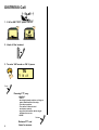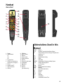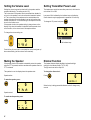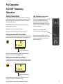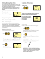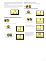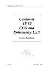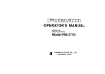
1
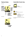
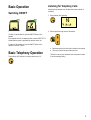
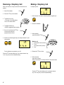
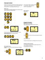
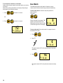
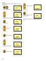
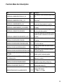
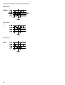
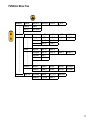
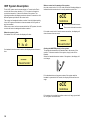
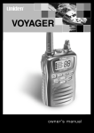
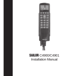
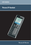
SAILOR A1 Basic VHF
Operating Instructions
Distress Call, see page ii. Contents, see page 1.
DISTRESS Call
1. If off or UNIT OFF: press ON/OFF.
2. Hook off the handset.
3. To enter VHF mode on CH 16 press
16
MEM
VOL
SQ
1 10 03
Press
Pressing PTT, say:
“MAYDAY”
“This is”
- the 9-digit identity and the call sign or
other identification of the ship,
- The ship’s position,
- The nature of distress and
assistance wanted,
- any other information which might
facilitate the rescue.
“OVER.”
Release
ii
Release PTT and
listen for answer.
Handset
What is What?
1
2
3
4
7
8
9
10
11
18
5
6
12
19
13
14
15
16
17
Abbreviations Used in this
Manual
1. Display
2. Indicator lamps
TX
1W
US
3. TX power level
4. INT/US (for information on
the BI version, see page 7.)
5. Dimmer
6. Speaker ON/OFF
7. Channel selection
8. Shift key
9.
10.
11.
12.
13.
14.
15.
16.
17.
18.
19.
FUNC key
ON/OFF button
Earpiece
Volume control
Squelch selection
Intercom
Channel 16 quick select
Loudspeaker
Microphone
PTT key
25W key
(US versions only)
ADDR
ATIS
BI
CU
DSC
DUP
DW
GMDSS
GPS
LF
MEM
MMSI
MSG
PTT
RX
SQ
STN
TEL
TX
UTC
Address
Automatic Transmitter Identification System
Channel Mode used when sailing on European rivers
(details on p. 7)
Control Unit
Digital Selective Calling
Duplex
Dual Watch
Global Maritime Distress and Safety System
Global Positioning System
Low Frequency
Memory
Maritime Mobile Service Identity
Message
Push-To-Talk (talk button)
Receive(r)
Squelch
Station
Telephony
Transmit(ter)
Coordinated Universal Time
iii
Introduction
About this Manual
For more than half a century, Sailor has been synonymous with highquality maritime communication equipment.
This manual is for the daily user of the system. The manual includes
two main sections, “basic” operation and “full” operation. The basic
part offers a short easily-read description of the main functions; the
full part offers elaborate descriptions of the functions of the product.
When it comes to making use of the very latest technology, S. P.
Radio is at the forefront. We are ready for the future, both technologically and commercially, and will continue to supply top-quality
equipment for global communication in the years to come.
S. P. Radio’s experience in maritime safety and communication is
extensive; the company has built as many as 250,000 VHF units,
mainly for the professional market. One of the main reasons for this
huge success is continual product development, which makes it
possible for us to offer products that are truly excellent in terms of
quality, sturdiness, ease of operation, and compact design.
Please note
Any responsibility or liability for loss or damage in connection with
the use of this product and the accompanying documentation is
disclaimed. The information in this manual is furnished for informational use only, is subject to change without notice, may contain
errors or inaccuracies, and represents no commitment whatsoever.
This agreement is governed by the laws of Denmark.
Doc. No.: B4900GB0
The SAILOR A1 Basic and A1 DSC are part of the new SAILOR
System 4000. This is a full range of maritime communication
equipment developed to increase safety and ease communication for
all kinds of vessels: leisure boats, fishing vessels, cargo ships, and
cruise liners.
As our central concern is fast and professional service, we have
introduced the SAILOR Certified Service Centre (CSC) concept.
This, we feel, is the ultimate way of ensuring a high level of service,
continuously monitored and adjusted.
Today S. P. Radio is the leading VHF supplier in the world, represented in 90 countries around the world. Consequently we are able
to service your SAILOR VHF equipment in the best way possible. No
matter where.
iv
Issue: H/0139
Contents
DISTRESS Call ..................................................................... ii
Handset ................................................................................ iii
What is What? .................................................................. iii
Abbreviations Used in this Manual .................................. iii
Introduction ......................................................................... iv
About this Manual .............................................................. iv
Telephony Display ............................................................... 2
Handset Main Function Keys ............................................. 2
Basic Operation ................................................................... 3
Switching ON/OFF ........................................................... 3
Basic Telephony Operation ................................................ 3
Listening for Telephony Calls ........................................... 3
Receiving a Telephony Call ............................................. 4
Making a Telephony Call .................................................. 4
Channel Control ............................................................... 5
Squelch Control ............................................................... 5
Setting the Volume Level ................................................. 6
Muting the Speaker .......................................................... 6
Setting Transmitter Power Level ...................................... 6
Dimmer Function .............................................................. 6
Full Operation ...................................................................... 7
Full VHF Telephony Operation ........................................... 7
Setting Channel Mode ..................................................... 7
Setting International/US Channel Mode .......................... 7
Setting International/BI Channel Mode ............................ 7
25W Transmitter Power Level ......................................... 7
Setting Memory Scan Table ............................................. 8
Scanning of Channels ...................................................... 8
Dual Watch ..................................................................... 10
Keyboard Lock ................................................................ 11
Intercom .......................................................................... 11
Function Menu ................................................................... 13
Function Menu Item Description .................................... 15
FUNCtion Menu Tree ..................................................... 17
VHF System Description ................................................ 18
International Channels ...................................................... 19
US Channels ....................................................................... 20
BI Channels ........................................................................ 21
1
Telephony Display
Handset Main Function Keys
Normal display
ON/OFF key.
Turns the handset on or off.
“16” key.
Selects TELEPHONY mode and channel 16.
Scanning display
Function menu.
Enters the function menu to set up the
handset and system.
If function menu is active it enters
VHF telephony mode.
After 5 minutes of inactivity the handset will resume in telephony
mode by default.
2
Basic Operation
Switching ON/OFF
Listening for Telephony Calls
According to international rules, all ships shall monitor channel 16
constantly:
1. Select channel 16 by pressing:
16
MEM
VOL
SQ
1 10 03
2. Set the squelch level by means of the buttons
To switch on the handset unit, push the ON/OFF button on the
handset.
If the handset unit is off, the display is blank or shows “UNIT OFF” to
indicate that the system is operated from another control unit.
To switch off the handset unit, push the ON/OFF button on the
handset for at least 1 second.
Basic Telephony Operation
To activate the VHF functions if not active press the key “16”.
a. Step down squelch level until noise is heard on free channel.
b. Then step up to the first level where just silent.
(To listen for calls on other channels, select the channel number
or use the scanning facility.)
3
Receiving a Telephony Call
Making a Telephony Call
When a call comes in, and your call name is heard in the loudspeaker:
In telephony mode:
1. Hook off the handset.
74
Press
MEM
VOL
SQ
1 08 02
2. Press the PTT key on the handset.
1. Select channel 16 or another channel specified or agreed upon:
3. To answer the call, say:
“<The name of the calling station>
This is <Your station name>“
2. Hook off the handset.
4. To suggest channel, say:
“Channel <suggested channel number>”
5. Say “over” and release the PTT key
to let the caller accept the
proposed channel number.
Release
3. When speaking,
press the handset PTT key.
Press
6. Switch to the channel agreed upon (for example channel 71) and
communicate:
71
MEM
VOL
SQ
0 10 03
For short-distance communication, use 1W.
Make the call:
1. <Called station name (3 times)>
2. “This is “
<Your station name (3 times)>
3. “Over”
4. Release the PTT key to listen.
Release
Press the PTT key when talking only. If on a simplex channel, say
“over” every time you have completed talking.
5. When answered,
agree upon a channel,
switch to the channel (for example channel 6) and communicate.
6
MEM
VOL
SQ
1 08 02
Press the PTT key when talking only. If on a simplex channel,
say “over” every time you have completed talking.
4
Channel Control
Setting the VHF channel can be done in three ways by means of the
numeric input keys (sequentially) or by means of the function “next
channel up/down”, or by using the quick select key “16”:
Numeric keys:
Press the numeric input keys (sequentially) until the desired channel
number is shown on the handset display:
The next channel function is active until the key
is released again, toggling through the
channels as long as pushed.
Quick select key:
Press the key
16
.
MEM
VOL
SQ
1 10 03
Squelch Control
Manual squelch level setting:
Set the squelch sensitivity of the receiver by buttons
Ex:
71
MEM
VOL
6
SQ
MEM
0 10 03
VOL
SQ
1 08 02
If private channels are available in your VHF system, a private
channel number is selected by pushing the buttons:
Ex: Private channel 23
Press
up/down automatically.
P23
MEM
VOL
for more than 4 seconds and the squelch level goes
The squelch setting is shown on the display below the “SQ” symbol.
SQ
0 09 01
Next channel function:
To select the next channel up or down (starting point is displayed
channel).
71
Push
MEM
VOL
Automatic squelch level setting:
The VHF system automatically sets the optimal squelch level to
mute the background noise level.
To set squelch level automatically:
Press
SQ
0 09 01
5
Setting the Volume Level
Setting Transmitter Power Level
Setting the volume level can be done both for the speaker and the
earpiece individually. (The setting can be 0-15).
The volume level of the speaker can be controlled when handset is
on hook, or the speaker is set to be active when handset is hooked
off. The volume level of the earpiece can be controlled when the
handset is hooked off, and the speaker is not set to be active when
handset is hooked off. The volume setting for the earpiece can also
be set in the function menu.
If the speaker is active the speaker setting is always shown on the
display. Only when the handset is hooked off and the speaker is not
set to be active, is the volume level of the earpiece shown.
The handset can control the transmitter power level, which can be
set to either 1W or 25W.
Low power 1W is indicated by the indicator lamp on the display.
Some channels may be programmed to operate at 1W level only.
.
To change the TX power level press
16
To change the volume setting use
MEM
VOL
SQ
1 08 04
6
the key
MEM
VOL
1W indicator lamp
SQ
1 10 01
Press the key for more than 1 second and the volume level goes up/
down automatically (until the volume limit is reached).
Muting the Speaker
Dimmer Function
If the speaker is active the handset automatically mutes the speaker
when the PTT is pressed, and then reactivates the speaker when the
PTT is released.
The handset features display backlight, keyboard backlight
and light in the indicator lamps (TX, 1W, US).
The light can be set at four steps 0-3.
The speaker icon on the display shows the speaker state.
To change the dimmer level:
Speaker active:
Press
To mute the speaker, press:
6
MEM
VOL
SQ
1 08 04
Speaker muted:
To reactivate the speaker, press:
6
MEM
VOL
SQ
1 08 04
6
6
LEVEL 2
When the key is being pressed the dimmer level will change every
second.
Full Operation
Full VHF Telephony
Operation
Setting Channel Mode
25W Transmitter Power Level
Some VHF radios offer a choice between two sets of channels,
called channel modes. If your VHF features two modes, you can
either switch between international/US channels, or between
international/BI channels.
NB! For US channels 13 and 67.
If the VHF is programmed with the set of US
channels, some of those channels are
specified to be used only with the limited
transmitter power level of 1W. This means
that the TX power level cannot be changed
to 25W as described.
International mode is used when sailing on any sea in the
world, except in US waters.
US mode is used when sailing in US waters.
BI mode is used when sailing on the rivers of Europe.
Setting International/US Channel Mode
If your VHF features the choice of international/US mode, switching
between those two sets of channels is done by pressing the key:
However, it is still possible to set
the TX power level to 25W by using:
The TX power level of 25W is only active
while the key is being pressed down; when
the key is released the TX power level is
again reduced to 1W.
6
MEM
VOL
SQ
1 08 01
Channel mode indication
When US mode is selected, the yellow US indicator lamp is lit.
Otherwise, the radio is in international mode.
Setting International/BI Channel Mode
If your VHF features the choice of international/BI mode, switching
between those two sets of channels is done by pressing the key:
6
MEM
VOL
SQ
1 08 01
Channel mode indication
When BI mode is selected, the yellow BI indicator lamp is lit.
Otherwise, the radio is in international mode.
When BI mode is selected, ATIS is activated automatically.
7
Setting Memory Scan Table
Scanning of Channels
The VHF 4000 system has eight independent sets of memory tables
to save channels for making scanning sessions. Each memory table
may contain all channels available in the system.
To distinguish between the tables, each table has a number (0-7)
and to each number can be attached a name of maximum seven
characters.
To attach a name to a scan table, enter the function menu.
The scan table number
selected is shown in the
left corner of the handset display.
6
MEM
VOL
SQ
7 09 01
Pre-programmed memory tables for scanning of channels:
Table 6:
Channels for intership communication.
Table 7:
All channels in system.
To start scanning:
Press
Pr MEM
P-CH
7 ALL 16
The lower part of the display shows from left to right: scan table
number, scan table name, priority channel of scan table.
If scan table contains no channels,
no scanning will be started, and the
display will show the
following message:
MEM EMPTY
It is recommended not to alter the pre-programmed channels in
scanning tables 6 and 7. These scanning tables are used to search
for channels for intership DSC communication, and altering the
channels may exclude you from performing intership communication
on certain channels.
To stop scanning:
Scanning in progress can be terminated in the following ways:
1. Press
Setting the selected scan table:
To set the selected scan table to be number 0:
The system resumes normal VHF operation on the channel
selected before the scanning session was initiated.
SEL
1. Press
2. Press
MEM
The system resumes normal VHF operation on quick select
channel “16”.
7 ALL
The handset display shows the message “SEL”ect and the MEM
symbol flashes. The lower part of the display shows the scan
table’s number and name.
3. Hook off the handset.
The system resumes normal VHF operation on the channel
selected before the scanning session was initiated.
4. Push the PTT
6
2. Press
MEM
The display now shows
the new scan table number 0.
8
VOL
SQ
0 09 01
If no signal has been detected on any channel, the system
resumes normal VHF operation on the channel selected before
the scanning session was initiated. If a signal has been detected
on a channel, the system resumes normal VHF on the last
channel where signal was detected.
If scanning is in progress and a signal is detected on eg. channel 6,
the display changes to show the selected channel number and
volume level.
When a priority scanning is in progress, channel 16 is scanned once
for every channel scanned in the scan table. Channel 16 cannot be
deleted or excluded while a scanning is in progress.
6
MEM
VOL
7 09
To delete a channel from a scan table:
Select channel number (shown on the display), and then
press
Ex: To delete channel 6 from scan table number 1:
6
1. Press
P-CH
16
Channel 6 is selected.
MEM
VOL
SQ
1 08 04
To add a channel to a scan table:
Select channel number (shown on the display), and then press
6
2. Press
The message “delete channel”
is shown for one second.
DELETE CH
Ex: To add channel 6 to scan table number 1:
1. Press
6
Channel 6 is selected.
MEM
VOL
Then the display will show
the next channel in the scan table.
The message “stores channel” is
shown for two seconds.
VOL
SQ
1 09 01
SQ
6
7
MEM
1 08 04
2. Press
DUP
If there are no more channels in
the scan table and deletion is
attempted, the display will show
the message “mem empty”.
MEM EMPTY
STORES CH
9
To view contents of channels in a scan table:
Viewing which channels a specific scan table contains, can be done
in two ways:
While the key is being pressed down, the display will step through
the channels of the scan table selected.
1. Press
, the latter for 1 second.
Dual Watch
The handset may perform a dual watch of channels, a priority
channel and the selected channel being monitored simultaneously.
To start a dual watch with channel 6 and priority channel 16:
Select channel 6.
Then press
OR
6
DW
2. Press
, the latter for 1 second.
12
MEM
7 CONTENT
When a dual watch is in progress, “DW”
appears in the top left corner of the
display and the priority channel is shown
in the bottom right corner of the display.
MEM
VOL
P-CH
1 08
16
To stop a dual watch: When a dual watch is in progress it can be
terminated in three ways.
1. Press
2. Push PTT
6
MEM
VOL
SQ
1 08 04
The system resumes VHF on the selected channel 6 and starts
transmitting.
16
3. Push
MEM
VOL
SQ
1 08 04
The system resumes VHF on the quick select channel (normally
16).
10
Keyboard Lock
Intercom
The handset has a keyboard lock, which locks some keys to avoid
unintentional channel changes during a telephony session.
When the keyboard is locked the only functions that can be controlled are:
If your VHF system has more than one control unit, it is possible to
carry out an intercom between two control units.
When the intercom feature is used the handset will perform as
follows:
1. Setting the volume level.
2. Setting the squelch level.
3. Channel up/down.
Initiating an intercom from the handset to another control unit:
To call another control unit:
IC
1. Press
SELECT NO
To lock the keyboard:
Press
(second time, press for 1 second).
6
MEM
VOL
This display indicates that the handset expects an input of the
location number to be called.
2. Press a numeric key to choose location to be called
SQ
1 08 04
The key symbol appears, indicating that the keyboard is locked.
Unlocking the keyboard can be done in two ways:
6
1. Press
MEM
The keyboard is unlocked.
VOL
Ex:
SQ
1 08 04
3. If location 2 is NOT available,
the display shows
2. Press
16
for 1 second.
The keyboard is unlocked
and channel 16 selected.
MEM
VOL
and no dialling is carried out.
SQ
IC2
NOT AVAIL
1 08 04
If location 2 is available the
display shows
and a ringing tone is heard in
the speaker/earpiece.
IC2
CALLING
11
This indicates that a dial-up is in progress to the control unit with
location number 2. The lower part of the display now toggles the
message CALLING and the NAME of the called control unit.
During the dialling time of 30 seconds it is possible to hook off
the handset and speak into the microphone. As LF is activated in
the called control unit during dialling, the receiver of the call can
hear you in the speaker without hooking off. This makes it
possible to use the VHF system as a sort of paging system.
4. If the intercom attempt is answered:
When the receiver of the call
hooks off his handset, the
intercom is established.
IC2
During intercom the handset is able to:
“NAME”
If the intercom attempt is not
answered:
If the receiver of the call does not
answer the intercom within
30 seconds, the handset
automatically hangs up and
reenters normal VHF operation.
1. Adjust volume level
16
MEM
VOL
SQ
1 10 03
Receiving an intercom attempt from another control unit:
When an intercom is attempted from another control unit to the
handset, this will act as illustrated in the following example, where
the caller has location number 3.
1. Receiving an intercom
The display toggles CALLING
and the NAME of the caller.
A ringing tone is heard in the speaker.
IC3
CALLING
2. To answer the intercom, hook off handset.
2. Mute/unmute speaker
3. Adjust squelch level
4. Adjust dimmer level
Terminating an intercom session:
The intercom connection can be terminated by either of the control
units.
To end an intercom:
1. Place handset on hook.
The handset resumes in VHF mode.
2. Key
The handset resumes in VHF mode.
The intercom connection between the two control units is now
established; to communicate, simply press PTT and speak into the
microphone.
12
3. Key
The handset resumes in VHF mode selecting channel “16”.
4.
Function Menu
The function menu offers facilities to view and set up the functionality
of the handset unit. It also offers facilities to view and change
functionality of the VHF transceiver and of the DSC modem as well.
To enter the function menu.
To view or set any specific items in the function menu press the keys
___
FUNC
a. To enter an alphanumeric character in the
cursor’s place.
TELEPHONY
To move around in the function menu use the keys:
1.
:
To set menu entry to be entered.
To leave the function menu:
NB: If any setting has been changed when leaving the function
menu, the handset has to be turned off and then on again for the
changes to take effect.
The function menu can be left in the following ways:
2.
:
To enter the entry set in 1.
3.
:
To reenter the function menu (press for 1 second).
1.
:
Activates VHF mode, selecting channel 16
16
MEM
VOL
SQ
1 08 04
To edit items in the function menu, use the keys:
2.
1.
:
a. To change option “Y”/“N”.
b. To change single numeric value,
up or downwards until limit.
2.
:
a. To save/select item setting, entering the
next item too.
b. To move one step to the right in an item with more
inputs.
3.
:
a. To reenter the function menu (press for 1
second).
b. To delete the character to the left of the cursor
(moving one step to the left in an item).
:
Activates VHF mode
13
Example:
To activate keyboard “beep” function for keyboard to beep every time
a key is pressed.
1.
:
Enters the function menu
2.
:
___
FUNC
___
FUNC
Pushed twice, finds the general entry
:
Enters the entry
: Finds the entry
4.
___
FUNC
ILLUMIN
___
FUNC
SOUND
5.
: Enters the sound entry
___
FUNC
EARPIECE
6.
:
Pushed twice, finds the entry
7.
: Enters keyboard entry
___
FUNC
KEYBOARD
___
SELECT
FUNC
KB.BEEP N
14
FUNC
8.
:
Edits item Y(es)/N(o)
KB.BEEP Y
TELEPHONY
GENERAL
3.
SELECT
When Y(es)...
9.
:
Selects the setting and reenters
the function menu
___
FUNC
TELEPHONY
To activate the new settings, turn the handset off and then on
again.
Function Menu Item Description
Path:
Data:
GENERAL\ILLUMIN\INDICATOR\LEVL_0-3
0-3
GENERAL\ILLUMIN\DISPLAY\DB_L_0-3
0-9
GENERAL\ILLUMIN\DIMMER\D_LEVL
0-3
GENERAL\ILLUMIN\DIMMER\D_LEVL\DIMDIR
0-2
GENERAL\ILLUMIN\KEYB0ARD\SECS
0-20
GENERAL\ILLUMIN\KEYB0ARD\SECS\D_LEVL 0-3
GENERAL\SOUND\EARPIECE\NORM
0-15
GENERAL\SOUND\EARPIECE\NORM\ALARM
0-15
GENERAL\SOUND\LOUDSPEAK\NORM
0-15
GENERAL\SOUND\LOUDSPEAK\NORM\ALARM 0-15
GENERAL\SOUND\LOUDSPEAK\NORM\ALARM
\EXT_SPK
0-3
GENERAL\SOUND\LOUDSPEAK\NORM\ALARM
\EXT_SPK\HO_SPK
0-1
GENERAL\SOUND\KEYB0ARD\KBBEEP
GENERAL\SOUND\SIDETONE\ST ATT
SERVICE\TELEPHONY\CH+MODE\INPUTS
Description:
Light intensity of each indicator lamp dimmer
level.
Light intensity of each display backlight
dimmer level.
Dimmer level when handset is turned on.
Dimmer level start direction (see diagram on
next page).
Number of seconds that handset light is on
after a key has been pushed.
Dimmer level when any key has been pushed
(provided number of seconds in item above is
1 or more)
Earpiece normal volume level when handset
is turned on.
Earpiece alarm volume level when receiving
DSC call or intercom.
Speaker normal volume level when handset
is turned on.
Speaker alarm volume level when receiving
DSC call or intercom.
Handset control of external speaker.
Speaker state when handset is hooked off.
Default on=1 or off=0.
"Y"/"N" Keyboard key beep when pushing key.
Feedback level of microphone to earpiece
0-3
(recommended setting=1).
Setup of number of input digits when
changing VHF channel.
"Y"/"N" Y = 3 digits, N = 2 digits
15
The dimmer start direction can be set up in three different ways:
Start direction 0:
Start direction 1:
Start direction 2:
16
FUNCtion Menu Tree
Telephony
|
|
|
General
|
|
|
|
|
|
|
|
|
|
|
|
|
Service
Scanner
Squelch
Atis no
Mem-no X Name XXX
Mode X
XXXXXXXXX
Pr-ch XX
Pr_sc X
Illumin
|
|
|
|
Sound
|
|
|
|
|
Version
Indicator
Display
Dimmer
Keyboard
Levl_0 X
Levl_0 X
D_levl X
Secs XX
Levl_1 X
Levl_1 X
D_dir X
D_levl X
Levl_2 X
Levl_2 X
Levl_3 X
Levl_3 X
Earpiece
Loudspeak
Keyboard
Sidetone
Norm XX
Norm XX
Beep X
St att X
Alarm XX
Alarm XX
Extspk X
Ho spk X
Handset
Transceiv
Software
Software
XXXXXX
XXXXXX
Serial no
Serial no
XXXXXXXX
XXXXXXXX
Code XXX
Bus setup
Telephony
Handset
Ch_Mode
Loc_No X
Inputs X
Name XXX
17
VHF System Description
To the VHF system can be connected up to 7 control units. Each
control unit has a unique location (1-7). If a control unit wants to
control the transceiver, it has to be master of the system. The
following describes the display read-outs shown in connection with
different system priorities of the control units:
The control unit assigned location number 1 has the highest priority
in the VHF system and is able to become master of the system at
any time needed.
When more control units are connected to the VHF system, the main
control unit has to be assigned location number 1.
When the system is free:
If a handset is in VHF mode, the display will show.
6
MEM
VOL
SQ
1 08 02
If a handset’s function menu is active, the display shows the menu
item.
___
When a control unit is master of the system,
the other control units, if in VHF mode, show the following display to
indicate that the transceiver is in use by another control unit:
oCC
1 BRIDGE
The control unit location name
The control unit location number
If the other control units’ function menus are active, the display will
show the menu item as usual.
___
TELEPHONY
Getting the MASTER priority in the system:
To operate the transmitter, the handset has to be master of the
system. To become master of the system, simply hook off the
handset.
When the handset becomes master of the system, the display will
not change.
TELEPHONY
If the handset does not become master of the system and the
handset is operated in VHF mode, the display will show the message:
oCC
1 BRIDGE
If the system is occupied by another control unit, hang up and wait
for the system to become free.
18
International Channels
&KDQQHOV
1
2
3
4
5
6
7
8
9
10
11
12
13
14
15
16
17
18
19
20
21
22
23
24
25
26
27
28
7;
0+]
156,050
156,100
156,150
156,200
156,250
156,300
156,350
156,400
156,450
156,500
156,550
156,600
156,650
156,700
156,750
156,800
156,850
156,900
156,950
157,000
157,050
157,100
157,150
157,200
157,250
157,300
157,350
157,400
5;
6,03/(;
'83/(;
0+] ,QWHUVKLS
3RUW
3RUW
3XEOLF
160,650
160,700
160,750
160,800
160,850
156,300
160,950
156,400
156,450
156,500
156,550
156,600
156,650
156,700
156,750
156,800 'LVWUHVVDQGFDOOLQJ
156,850
161,500
161,550
161,600
161,650
161,700
161,750
161,800
161,850
161,900
161,950
162,000
&KDQQHOV
60
61
62
63
64
65
66
67
68
69
70
71
72
73
74
75
76
77
78
79
80
81
82
83
84
85
86
87
88
7;
0+]
156,025
156,075
156,125
156,175
156,225
156,275
156,325
156,375
156,425
156,475
156,525
156,575
156,625
156,675
156,725
156,775
156,825
156,875
156,925
156,975
157,025
157,075
157,125
157,175
157,225
157,275
157,325
157,375
157,425
5;
6,03/(;
'83/(;
0+] ,QWHUVKLS
3RUW
3RUW
3XEOLF
160,625
160,675
160,725
160,775
160,825
160,875
160,925
156,375
156,425
156,475
156,525
'6&
'6&
156,575
156,625
156,675
156,725
156,775
/
156,825
/
156,875
161,525
161,575
161,625
161,675
161,725
161,775
161,825
161,875
161,925
157,375
157,425
Notes:
L)
*)
NB!
1 W TX power.
Due to the introduction of the channels AIS1 at 161.975 MHz
and AIS2 at 162.025 MHz for Automatic Identification
System, channels 87 and 88 became simplex channels as of
1 January.
The RX and TX frequencies can be read out on the control
unit handset display by pressing (for more than one second)
and holding the CH key.
At a front-operated VHF radio, the RX and TX frequencies can
be displayed on a menu.
19
US Channels
&KDQQHOV
1
2
3
4
5
6
7
8
9
10
11
12
13
14
15
16
17
18
19
20
21
22
23
24
25
26
27
28
7;
5;
6,03/(;
0+]
0+]
156,050 156,050
'83/(;
%
156,150 156,150
%
156,250
156,300
156,350
156,400
156,450
156,500
156,550
156,600
156,650
156,700
156,800
156,850
156,900
156,950
157,000
157,050
157,100
157,150
157,200
157,250
157,300
157,350
157,400
156,250
156,300
156,350
156,400
156,450
156,500
156,550
156,600
156,650
/
156,700
156,750
5;
156,800 'LVWUHVVDQGFDOOLQJ
156,850
156,900
156,950
157,000
157,050
157,100
157,150
161,800
161,850
161,900
161,950
162,000
&KDQQHOV
60
61
62
63
64
65
66
67
68
69
70
71
72
73
74
75
76
77
78
79
80
81
82
83
84
85
86
87
88
7;
0+]
B)
!)
RX)
NB!
20
6,03/(;
'83/(;
&KDQQHOV
%
P1
P2
P3
P4
P5
P6
P7
P8
P9
P10
156,075 156,075
%
156,175
156,225
156,275
156,325
156,375
156,425
156,475
156,525
156,575
156,625
156,675
156,725
156,175
156,225
156,275
156,325
156,375
156,425
156,475
156,525
156,575
156,625
156,675
156,725
/
'6&
%
%
156,875
156,925
156,975
157,025
157,075
157,125
157,175
157,225
157,275
157,325
157,375
157,425
Notes:
L)
5;
0+]
1 W TX power. By pressing the 25W button in the US hook,
the transmitter will transmit at 25W on channel 13 and 67,
which are normally limited to 1W transmission.
Channels 2, 4, 60, 62, 75 and 76 cannot be selected in US
mode.
Channels 3, 21, 23, 61, 64, 81, 82 and 83 may be legally
used in certain instances, but they are not for use by the
general public in US waters.
Only RX. Transmitter is blocked.
The RX and TX frequencies can be read out on the control
unit handset display by pressing (for more than one second)
and holding the CH key.
At a front-operated VHF radio, the RX and TX frequencies
can be displayed on a menu.
156,875
156,925
156,975
157,025
157,075
157,125
157,175
161,825
161,875
161,925
161,975
157,425
/
:;
WX1
WX2
WX3
WX4
WX5
WX6
WX7
WX8
WX9
WX10
5;
0+]
162,550
162,400
162,475
162,425
162,450
162,500
162,525
161,650
161,775
163,275
BI Channels
&KDQQHOV
1
2
3
4
5
6
7
8
9
10
11
12
13
14
15
16
17
18
19
20
21
22
23
24
25
26
27
28
7;
0+]
156,050
156,100
156,150
156,200
156,250
156,300
156,350
156,400
156,450
156,500
156,550
156,600
156,650
156,700
156,750
156,800
156,850
156,900
156,950
157,000
157,050
157,100
157,150
157,200
157,250
157,300
157,350
157,400
5;
6,03/(;
'83/(;
0+] ,QWHUVKLS
3RUW
3RUW
3XEOLF
160,650
160,700
160,750
160,800
160,850
156,300
/
160,950
156,400
/
156,450
156,500
/
/
156,550
/
156,600
/
156,650
/
/
156,700
/
156,750
/
/
156,800 'LVWUHVVDQGFDOOLQJ
156,850
/
/
161,500
161,550
161,600
161,650
161,700
161,750
161,800
161,850
161,900
161,950
162,000
&KDQQHOV
60
61
62
63
64
65
66
67
68
69
70
71
72
73
74
75
76
77
78
79
80
81
82
83
84
85
86
87
88
7;
0+]
156,025
156,075
156,125
156,175
156,225
156,275
156,325
156,375
156,425
156,475
156,525
156,575
156,625
156,675
156,725
156,775
156,825
156,875
156,925
156,975
157,025
157,075
157,125
157,175
157,225
157,275
157,325
157,375
157,425
5;
6,03/(;
'83/(;
0+] ,QWHUVKLS
3RUW
3RUW
3XEOLF
160,625
160,675
160,725
160,775
160,825
160,875
160,925
156,375
156,425
156,475
156,525
'6&
'6&
156,575
/
156,625
/
156,675
156,725
/
156,775
%
156,825
%
156,875
/
161,525
161,575
161,625
161,675
161,725
161,775
161,825
161,875
161,925
157,375
157,425
Notes:
B)
L)
*)
NB!
Channels 75 and 76 cannot be selected in BI mode.
1W TX power on channels 6, 8, 10, 11, 12, 13, 14 ,15, 17,
71, 72, 74, and 77.
Due to the introduction of the channels AIS1 at 161.975 Mhz
and AIS2 at 162.025 MHz for Automatic Identification
System, channels 87 and 88 became simplex channels as
of 1 January 1999.
- The ATIS function is enabled on all channels.
- The RX and TX frequencies can be read out on the control
unit handset by pressing (for more than one second) and
holding the CH key.
At a front-operated VHF radio, the RX and TX frequencies can
be displayed on a menu.
21
v