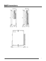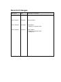
1
Safety Precautions
Observe the following notices to ensure personal safety or to prevent accidents.
To ensure that you use this product correctly, read this User’s Manual thoroughly before use.
Make sure that you fully understand the product and information on safety.
This manual uses two safety flags to indicate different levels of danger.
WARNING
If critical situations that could lead to user’s death or serious injury is assumed by
mishandling of the product.
-Always take precautions to ensure the overall safety of your system, so that the whole
system remains safe in the event of failure of this product or other external factor.
-Do not use this product in areas with inflammable gas. It could lead to an explosion.
-Exposing this product to excessive heat or open flames could cause damage to the lithium
battery or other electronic parts.
CAUTION
If critical situations that could lead to user’s injury or only property damage is
assumed by mishandling of the product.
-To prevent excessive exothermic heat or smoke generation, use this product at the values
less than the maximum of the characteristics and performance that are assured in these
specifications.
-Do not dismantle or remodel the product. It could cause excessive exothermic heat or smoke
generation.
-Do not touch the terminal while turning on electricity. It could lead to an electric shock.
-Use the external devices to function the emergency stop and interlock circuit.
-Connect the wires or connectors securely.
The loose connection could cause excessive exothermic heat or smoke generation.
-Do not allow foreign matters such as liquid, flammable materials, metals to go into the inside
of the product. It could cause excessive exothermic heat or smoke generation.
-Do not undertake construction (such as connection and disconnection) while the power
supply is on. It could lead to an electric shock.
Copyright / Trademarks
-This manual and its contents are copyrighted.
-You may not copy this manual, in whole or part, without written consent of Panasonic Electric
Works SUNX Co., Ltd.
-Windows is a registered trademark of Microsoft Corporation in the United States and other
countries.
-All other company names and product names are trademarks or registered trademarks of
their respective owners.
PLC_ORG
Table of Contents
Precautions before Usage
1 Unit Outlines................................................................................................................................. 1
1.1 Functions ..................................................................................................................................................... 1
1.2 Model ........................................................................................................................................................... 1
1.3 Unit Connection Limit .................................................................................................................................. 1
2 Part Names and Functions.......................................................................................................... 2
3 Input Range Setting Switch ........................................................................................................ 3
4 Wiring............................................................................................................................................ 4
5 Conversion Characteristic .......................................................................................................... 6
6 What is Averaging ? .................................................................................................................... 8
7 I/O Allocations and Program....................................................................................................... 9
7.1 I/O No. ......................................................................................................................................................... 9
7.2 Program ..................................................................................................................................................... 10
8 When Error Occurred ................................................................................................................ 13
8.1 What to Do................................................................................................................................................. 13
8.2 Digital Value when Out of Range .............................................................................................................. 13
9 Specifications............................................................................................................................. 14
9.1 Specifications............................................................................................................................................. 14
9.2 Dimensions ................................................................................................................................................ 17
Precautions before Usage
- Accuracy
・Connecting/disconnecting the Thermocouple input terminal block while the Thermocouple Unit is ON will
lower an accuracy temporarily. Accordingly, use the temperature data obtained 15 minutes after its action.
・When a high-accurate temperature data is required, use the temperature data obtained 15 minutes after
turning ON the Thermocouple Unit. (However, the temperature data within 15 minutes is also within the
Total accuracy range.)
・A rapid temperature change in the Thermocouple Unit might change the temperature data temporarily.
・The direct air (wind) from the cooling fan built in the control panel etc. to the Thermocouple Unit will lower
an accuracy. Prevent a direct air.
- Programming
・From the Power-ON to the converted data Ready, the digital value will be K8001 or K16001. Create a
ladder program not to use the data obtained during that period.
・When the thermocouple is broken, the digital value will change to K8000 or K16000 within 70 seconds.
Practice in the ladder program a process for avoiding a risk, would be resulting from a broken thermocouple,
and exchange the thermocouple.
・ When the Input range setting switch is set for 4 channels or more, use a program described in “7.2
Program>, without fail.
1 Unit Outlines
1.1 Functions
1. Thermocouple input unit for FP0/FPΣ Control Unit
The temperature data obtained using the thermocouple is converted to the digital value to be read into the
FP0/ FPΣ Control Unit.
2. Thermocouple types K, J, T and R are available.
3. 3 temperature measurement ranges are available.
-100.0 to +500.0
(Thermocouple types: K and J)
-100.0 to +400.0
(Thermocouple type : T)
0.0 to +1500.0
(Thermocouple type : R)
4. The data can be converted to the degree Celsius or the degree Fahrenheit.
The temperature data measured using the sensor is converted to the degree Celsius or the degree
Fahrenheit inside the Thermocouple Unit.
5. The averaging function is installed.
The converted data (degree Celsius or Fahrenheit) is averaged, so that even unstable input signals can
be properly read.
6. The broken-thermocouple detector is attached.
A thermocouple, broken, can be detected.
1.2 Model
- Thermocouple Unit
Part number
FP0-TC4
FP0-TC8
Thermocouple
input points
4 points
8 points
Product number
AFP0420
AFP0421
1.3 Unit Connection Limit
- Number limit
Up to 3 expansion units can be connected with the Control Unit.
- Position limit
Install the thermocouple unit on the right side of other expansion unit. If it is installed on the left side, the
total
precision will deteriorate.
Reference: “7.1 I/O No.”.
1
2 Part Names and Functions
- Thermocouple Unit
①Input range setting switch
changes between the input ranges (thermocouple types). Only the same range setting is available for all
the 8 channels. (The setting can not be specified per channel.)
②Thermocouple input terminal block (9-pin)
is made by Phoenix Contact Co. Model No. is MC1.5/9-ST-3.5 (Part No.: 1840434)
Suitable wires
Size
Nominal cross-sectional area
AWG# 28 to 16
0.08 mm2 to 0.25mm2
③Expansion connector
Connects the expansion unit to the internal circuit of the Control Unit.
④DIN rail attachment lever (One-touch hook)
The unit can be installed to the DIN rail through one-touch operation.
This is also used for installing the unit to the FP0 Slim Type Mounting Plate (AFP0803).
⑤Expansion hook
Fixes the expansion unit with the Control Unit.
2
3 Input Range Setting Switch
MODE
ON
OFF
- Input range setting switch
1
2
3
4
5
(The following switch settings are read once when the Control Unit is turned ON. Any change will not be
reflected even if made while ON.)
1) Input range setting switch
OFF
MODE SW
ON
OFF
ON
OFF
ON
OFF
ON
1
2
Thermocouple type
K
2) Temperature unit switch
OFF
MODE SW
ON
OFF
T
R
ON
3
℃
Unit
3) Input channel selection switch
OFF
MODE SW
J
℉
ON
OFF
ON
OFF
ON
OFF
ON
4
5
Input channel
CH0, 1
Number of input
2
channels
* Do not specify it for the FP0-TC4.
CH0 to CH3
CH0 to CH5
CH0 to CH7
4
6*
8*
3
4 Wiring
- Wiring method
- Input line wiring
・Keep the space more than 100mm between the input line and the power line/high-voltage line.
・It is recommended grounding the unit using the insulated compensating wire.
4
- Input terminal block
Pin No.
1
2
3
4
5
6
7
8
9
1
2
3
4
5
6
7
8
9
Name
CH.0 +
CH.0 CH.1 +
CH.1 CH.2 +
CH.2 CH.3 +
CH.3 NC
Function
CH0 + thermocouple input
CH0 - thermocouple input
CH1 + thermocouple input
CH1 - thermocouple input
CH2 + thermocouple input
CH2 - thermocouple input
CH3 + thermocouple input
CH3 - thermocouple input
no connection
CH.4 +
CH.4 CH.5 +
CH.5 CH.6 +
CH.6 CH.7 +
CH.7 NC
CH4 + thermocouple input
CH4 - thermocouple input
CH5 + thermocouple input
CH5 - thermocouple input
CH6 + thermocouple input
CH6 - thermocouple input
CH7 + thermocouple input
CH7 - thermocouple input
no connection
* Where between channels are insulated using the PhotoMos relay.
5
5 Conversion Characteristic
- K and J range (-100.0℃ to 500.0℃)
When the input out of the range is made
Input
converted to
K -1001
-100.1℃ Max.
K 5001 or K 8000
500.1℃ Min.
When the thermocouple
K 8000
is broken
- R range (0.0℃ to 1500.0℃)
When the input out of the range is made
Input
converted to
K0
0.0℃ Max.
K 15001 or K 16000
1500.1℃ Min.
When the thermocouple
K 16000
is broken
6
- T range (-100.0℃ to 400.0℃)
When the input out of the range is made
Input
converted to
K -1001
- 100.1℃ Max.
K 4001 or K 8000
400.1℃ Min.
When the thermocouple
K 8000
is broken
- K and J range (-148.0℉ to 790.0℉)
When the input out of the range is made
Input
converted to
K -1481
148.1℉ Max.
K 7901 or K 8000
790.1℉ Min.
When the
K 8000
thermocouple is
broken
- T range (-148.0℉ to 752.0℉)
When the input out of the range is made
Input
converted to
K -1481
-148.1℉ Max.
K 7521 or K 8000
752.1℉ Min.
When the
K 8000
thermocouple is
broken
- R range(32.0℉ to 1590.0℉)
When the input out of the range is made
Input
converted to
K 320
32.0℉ Max.
K 15901 or K 16000
1590.1℉ Min.
When the
K 16000
thermocouple is
broken
Note: The measurement range available for degree Celsius is not available for degree
Fahrenheit, of which the upper-limit measurement is set lower than degree Celsius, since
the digital value (temperature value displayed) for degree Fahrenheit is bigger than that for
degree Celsius.
7
6 What is Averaging ?
The followings are processed inside the Thermocouple Unit.
The example below is for when the number of the input channels is 2. (The input range setting switches,
No.4 and No.5, are OFF.)
The values for the 6-time measurements, from the latest 8-time measurements, excluding the Max. and the
Min., are averaged and the newest average is always output to WX2 and WX3. (The decimal fractions are
rounded off.)
8
7 I/O Allocations and Program
7.1 I/O No.
- I/O No.
Note: *Install the thermocouple unit on the right side of other expansion unit. If it is installed on the
left side, the total precision will deteriorate.
*In case of 3 expansion unit (1 of which is the Thermocouple Unit): Mount the Thermocouple
Unit in the place of Expansion Unit, 3.
*In case of 3 expansion unit (2 of which is the Thermocouple Unit): Mount the Thermocouple
Unit in the places of Expansion Units, 2 and 3.
- The data from each channel is assigned as the I/O data to the data registers below when the A/D Converter
Unit is installed in the above unit configuration;
Thermocouple Unit
input channel
CH0, 2, 4, 6
CH1, 3, 5, 7
Expansion Unit, 1
Expansion Unit, 2
Expansion Unit, 3
WX2
WX3
WX4
WX5
WX6
WX7
- Example of the I/O allocations
The converted data for channels when the Thermocouple Unit is installed in the Expansion Unit, 1 and its
assignment to WX2 and WX3
WX3
WX2
X X X X X X X X X X X X X X X X
3 3 3 3 3 3 3 3 3 3 3 3 3 3 3 3
F E D C B A 9 8 7 6 5 4 3 2 1 0
bit F
A A
1 0
bit 0
Converted data for CH1, 3 ,5 and 7
(signed 14-bit data)
X X X X X X X X X X X X X X X X
2 2 2 2 2 2 2 2 2 2 2 2 2 2 2 2
F E D C B A 9 8 7 6 5 4 3 2 1 0
bit 0
bit F
Converted data for CH 0, 2, 4 and 6
(signed 16-bit data)
Conversion data switch flag
A1
0
0
1
1
A0
0
1
0
1
WX3
CH1 data
CH3 data
CH5 data
CH7 data
WX2
CH0 data
CH2 data
CH4 data
CH6 data
9
7.2 Program
7.2.1 Thermocouple Types K, J and T
- Ladder program to read the data from input channels
The program to store in the data registers, DT0 to DT7, the temperature
data for CH0 to CH7 of the Thermocouple Unit installed in the 1st.
Reference: “7.1 I/O No.”.
10
- Conversion data switch flag
When transferring the data from the Thermocouple Unit to the Control Unit, it is converted to the 32-bit data
including the channel information. The data for WX2 can be used as is, but the following process is required
for the WX3 data since its higher 2 bits are used as a conversion data switch flag;
- What to do
When the temperature data is negative, the data for WX2 and WX3 will be 2’s complement.
That is, bit F for WX2 and bit D for WX3 will be “1”.
The higher 2 bits for WX3 are used as the conversion data switch flag, so that masking using “00” is
needed when the conversion data is positive, using “11” when negative.
Data for CH3
1
-1
recognizes Positive or
Negative at bit D.
WX3
0100000000000001
0111111111111111
→
→
→
Data after masked
0000000000000001
1111111111111111
The above values to be masked.
Conversion data switch flag
Note: X3D, X3E, X3F, WX2 and WX3 are changed depending on where the Thermocouple Unit is
installed.
11
7.2.2 Thermocouple Types, R
- Ladder program to read the data from input channels
The program to store in the data registers, DT0 to DT7, the temperature
data for CH0 to CH7, of the Thermocouple Unit installed in the 1st.
Reference: “7.1 I/O No.”.
- Conversion data switch flag
When transferring the data from the Thermocouple Unit to the Control Unit, it is converted to the 32-bit data
including the channel information. The data for WX2 can be used as is, but the following process is required
for the WX3 data since its higher 2 bits are used as a conversion data switch flag;
- What to do
The temperature data is positive only, so that the data of bit 0 to bit F for WX2 and bit 0 to bit D for WX3
can be handled intact as a temperature.
The higher 2 bits for WX3 are used as the conversion data switch flag, so that masking using “00” is
needed.
Data for CH3
1
WX3
0100000000000001
→
→
Data after masked
0000000000000001
The above values to be masked
Conversion data switch flag
Note: X3E, X3F, WX2 and WX3 are changed depending on where the Thermocouple Unit is
installed.
12
8 When Error Occurred
8.1 What to Do
What to do ①
Check whether the input signal line are properly connected.
When the thermocouple is not connected properly or broken, K8000 is displayed for the
Thermocouple type K, J and T and K16000 for R.
What to do ②
Check whether the Input range setting switch (, which specifies the allowable temperature range,
the thermocouple type and the valid channel) is properly set.
What to do ③
Use the program described in “7.2 Program” when the number of input channels are more than 4.
Reference: “3 Input Range Setting Switch”.
Reference: “7 I/O Allocations and Program”.
8.2 Digital Value when Out of Range
When the input of the FP0 Thermocouple Unit is out of the range, the digital values below are displayed;
K, J range
T range
R range
℃
℉
℃
℉
℃
℉
5001 or
7901 or
4001 or
7521 or
15001 or
15901 or
The temp-measured
8000
8000
8000
8000
16000
16000
>the upper-limit
The temp-measured
- 1001
- 1481
- 1001
- 1481
0
32
<the lower-limit
The thermocouple is
8000
8000
8000
8000
16000
16000
connected improperly
or broken
13
9 Specifications
9.1 Specifications
- General specifications
Item
Consumption current increased
for the Control Unit
Operating ambient temperature
Storage ambient temperature
Operating ambient humidity
Storage ambient humidity
Withstand voltage
Insulation resistance
Vibration resistance
Shock resistance
Noise immunity
Operating condition
Weight
14
Specifications
25mA Max. (24V DC)
0℃ to +55℃
-20℃ to +70℃
30%RH to 85%RH (at25°C no condensing)
30%RH to 85%RH (at25°C no condensing)
between “all the thermocouple input terminals” and “all the Control
unit power/functional earth terminals”: 500V AC for 1min.
between thermocouple input terminal channels: 200V AC for 1 min.
between “all the thermocouple input terminals” and “all the Control
unit power/functional earth terminals”: more than 100MΩ
(Testing voltage: 500V DC)
10Hz to 55Hz 1 sweep/min. with double amplitude in 0.75mm
for 10 min. on 3 axes (toward X, Y and Z directions)
98m/s2 for 4 times on 3 axes (toward X, Y and Z directions)
1000V [P-P] Pulse width 50ns, 1µs (using noise simulator)
Must be free from corrosive gases and excessive dust.
about 85g (FP0-TC4)
about 95g (FP0-TC8)
- Input specifications
Item
Specification
Input point
Up to 8 channels per unit (The number of Input points can be changed
2, 4, 6 and 8 channels are available.)
-100.0℃ to 500.0℃
Thermocouple types K, J
-148.0℉ to 790.0℉*1
-100.0℃ to 400.0℃
Input range
Thermocouple type T
-148.0℉ to 752.0℉*1
0.0℃ to 1500.0℃
Thermocouple type R
32.0℉ to 1590.0℉*1
Digital output
K and J (when using ℃)
: K - 1000 to K 5000
K and J (when using ℉)
: K - 1480 to K 7900*1
When range over using(℃) : K -1001, K 5001 or K 8000
When range over using(℉) : K -1481, K 7901 or K 8000
(when the thermocouple Broken: K 8000)*2
(Until the temperature can be measured at the initial startup: K 8001)*3
T (when using ℃)
T (when using ℉)
When range over using(℃)
When range over using(℉)
: K - 1000 to K 4000
: K - 1480 to K 7520*1
: K -1001, K 4001 or K 8000
: K -1481, K 7521 or K 8000
(when the thermocouple Broken: K 8000)*2
(Until the temperature can be measured at the initial startup: K 8001)*3
R (when using ℃)
R (when using ℉)
When range over using(℃)
When range over using(℉)
: K 0 to K 15000
: K 320 to K 15900*1
: K 0,
K 15001 or K 16000
: K 0,
K 15901 or K 16000
(when the thermocouple Broken: K 16000)*2
(Until the temperature can be measured at the initial startup: K 16001)*3
Resolution
Sampling cycle*5
Accuracy
Input impedance
Insulation method
Input/Output points
0.1℃
300ms : when using 2 channels for an input points*4
500ms : when using 4 channels for an input points*4
700ms : when using 6 channels for an input points*4
900ms : when using 8 channels for an input points*4
Range for K and J (-100℃ to 500℃) : ±0.8℃
Range for T
(-100℃ to 400℃) : ±0.8℃
Range for R
(0℃ to 99.9℃)
: ±3℃
(100℃ to 299.9℃) : ±2.5℃
(300℃ to 1500℃) : ±2℃
more than 1MΩ
・between thermocouple input terminals and Control Unit internal circuits
Photo-coupler insulation/DC-DC insulation
・between thermocouple input terminal channels
PhotoMos relay insulation
Input - 32 points 16 points for WX2, 4, 6: Analog input
CH0, 2, 4, 6 (WX2)*6*7
16 points for WX3, 5, 7: Analog input
CH1, 3, 5, 7 (WX3)*6*7
Output 32 points (reserved.)
15
*1 The measurement range available for degree Celsius is not available for degree Fahrenheit, of which the
upper-limit measurement is set lower than degree Celsius, since the digital value (temperature value
displayed) for degree Fahrenheit is bigger than that for degree Celsius.
*2 When the thermocouple is broken, the digital value will become K8000 or K16000 within 70 seconds
since broken. Practice in the ladder program a process for avoiding a risk, would be resulting from a
broken thermocouple, and exchange the thermocouple.
*3 Until the conversion data will be ready after the initial startup was made, the digital value shows K8001
or K16001. Those are not a temperature data. Create a ladder program, so that they are not acquired as
a temperature data.
*4 The settings of the Input channel selection switch.
*5 Conversion values for 6-time measurements (6 from the latest 8 measurements, excluding the Max. and
Min.) are averaged, so that it takes time for the digital value to be displayed due to the rapid temperature
change.
*6 The Control Unit reads the data for 2 channels per 1 scan by the Control Unit.
Read the data using the program described in 7.2.
*7 This changes depending on where the Thermocouple Unit is installed. (This is when the Thermocouple
Unit is installed in the 1st.)
- Insulation outline
Thermocouple Unit
Bus
FP Σ/FP0
Control Unit
24 V DC
(Increased
amount 25mA
Max.)
16
Analog input
circuit
I/F
+5 V
CH0
Photo-coupler
insulation
DC-DC converter
insulation
PhotoMos relay
channel switch
circuit (insulated
between
channels)
to
CH7
9.2 Dimensions
17
Record of changes
Manual No.
Date
Description of changes
ARCT1F366E
SEPT.2002
First edition
ARCT1F366E-1
FEB.2006
Second edition
ARCT1F366E-2
NOV.2008
Third edition
- Change in Corporate name
ARCT1F366E-3
AUG.2011
Fourth edition
- Change in Corporate name
- Fixed Errors