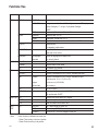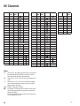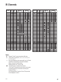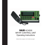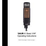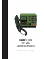
1
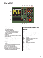
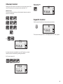
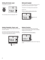
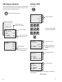
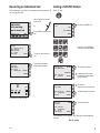
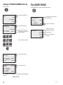
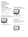
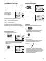
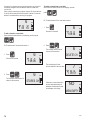
SAILOR RT4822
VHF-DSC
Operating Instructions
Distress Calls, see page ii . Contents, see page 1.
Acknowledgment
DISTRESS Call
Quick DISTRESS Call
1. If off or UNIT OFF: press ON/OFF.
Distress
acknowledgment received
FROM: 002191000
VIEW
Read call contents.
4. Press VIEW.
2. Open DISTRESS lid.
3. Press DISTRESS until RELEASE is displayed.
This takes 5 seconds, during which the indicator lamps TX and
ALARM will flash
5 - 4 - 3 - 2 - 1 - RELEASE
Press the DISTRESS button
for
5 seconds to transmit
TYPE
MSG.
Pos
Time
: Distress
: Undesignated
: N:05°01E:009°54
: 18.12 UTC
CANCEL
Call contents
first page
Time: 18.22.06 19 Aug 97
TYPE : All station
FROM: 002191000
CAT : Distress
ACK : Call
Call contents
second page
View next page.
MORE
CONNECT
COMM: Distress ackn
SHIP : 123456789
MSG. : Undesignated
Pos : N:05°01E:009°54
AGAIN
View call again.
Mayday Procedure
5. Press “16”.
16
MEM
VOL
25W
INT
SQ
2 13 06
6. Lift handset.
Waiting for
Distress
Acknowledgment
16
Retransmit distress
call every 4 minutes
Wait
for answer!
CANCEL
(The distress call is autorepeated every 3.5-4.5 minutes.)
NB!
ii
DISTRESS is only to be used in case of
an emergency!
Press
Press PTT and say:
“MAYDAY”
“This is”
- the 9-digit identity and the call sign or
other identification of the ship,
- The ship’s position,
- The nature of distress and
assistance wanted,
- any other information which might
facilitate the rescue.
“OVER.”
Release PTT and
listen for answer.
Release
0144
What is What?
14
13
12
11
5
6
7
8
10
9
1
2
3
4
1. Display.
2. Indicator lamps. Condition when lit:
Tx: Transmitting.
1W: 1 watt transmission mode.
US: US channel system activated.
(For information on the BI version, see page 11)
CALL: DSC (see button 10) call for you received.
ALARM: Alarm call received.
3. Loudspeaker.
4. Squelch control. Adjust to silent when no station is received.
5. ON/OFF push button.
6. Volume control.
7. Shift key. Press and hold for yellow functions.
8. DISTRESS button, protected by shield. To use, lift the shield and
press for 3 seconds, guided by the text displayed.
9. Keyboard.
10. TEL/DSC function switch.
In TEL mode radiotelephone parameters are shown and
selected.
In DSC mode DSC parameters are shown and selected.
11. Open the ADDR BOOK in DSC mode.
12. Tx CALL: Press to start creating a DSC call.
13. Open the Rx log of received calls in DSC mode.
14. Display keys. The function of each key is described in its
respective line on the right side of the display.
Abbreviations Used in this
Manual
ADDR
ATIS
BI
DSC
DUP
DW
GMDSS
GPS
LF
MEM
MMSI
MSG
PTT
RX
SQ
STN
TEL
TX
UTC
Address
Automatic Transmitter Identification System
Channel mode used when sailing on European rivers
(more details on p. 11)
Digital Selective Calling
Duplex
Dual Watch
Global Maritime Distress and Safety System
Global Positioning System
Low Frequency
Memory
Maritime Mobile Ship Identification
Message
Push-To-Talk
Receive(r)
Squelch
Station
Telephony
Transmit(ter)
Coordinated Universal Time
iii
Introduction
S. P. Radio A/S
For more than half a century S. P. Radio A/S has been the market
leader within maritime radio communication.
Sailor
The communication products and systems of S. P. Radio are
recognized under the brand name Sailor. The Sailor name has
become a guarantee of reliable and technologically superior radio
equipment, ranging from basic VHF units to satellite systems and
complete compact GMDSS solutions.
Products
The SAILOR COMPACT 2000 GMDSS is based on the well proven
range of Sailor products specifically developed to meet the GMDSS
requirements and supported by a world-wide Certified GMDSS
service concept, giving several hundred reasons for shipping
companies to choose equipment manufactured by S. P. Radio A/S.
Today S. P. Radio A/S is recognized as the world’s leading supplier
of GMDSS solutions.
The SAILOR COMPACT 2000 GMDSS has already been and still is
constantly supplied to a large number of the world’s leading shipping
companies and national naval fleets. It is a complete GMDSS
solution which matches communication and safety needs exactly regardless of whether you operate with A1, A2, A3 or A4.
The System 4000 GMDSS sets new standards. It is constructed on
the basis of our comprehensive experience developing GMDSS
equipment. It satisfies all the relevant requirements regarding safety
and efficiency. The System 4000 presents a large number of
attractive convenience and safety facilities, either as a complete
solution or as a series of stand-alone products.
Sailor has a long history as a satellite communications supplier
offering a full programme of satellite systems which includes Mini M,
SAT-C and a number of stationary satellite systems. Our SAT-B is a
breakthrough in maritime aerial technology and reliability. The SAT-B
is the best possible choice when high quality speech transmission,
top level security and the capacity to deal with large volumes of
telex, fax, data and high-speed data (HSD) transmissions are required.
Training certification
Training of deck officers to meet the requirements within the concept
of GMDSS, as to operation of equipment and basic understanding of
the systems, is an extremely important factor for the overall successful implementation of GMDSS. As a unique initiative for GMDSS
solutions, we can supply a complete software training programme for
on-board training, to be used as preparation in order to fulfil the
GMDSS requirements for obtaining the
General Operation Certificate.
iv
Service
A world-wide Sailor GMDSS certified service concept has been
established in order to provide the shipping industry with a highly
professional and uniform level of service. The Sailor GMDSS
Certified Service Centre concept, which is constantly monitored,
ensures that replacement units and spare parts are available at all
the Sailor Certified Service Centres around the world. Service
centres which are in position along all the major shipping routes.
Furthermore the Certified Service Centres ensure that technicians
with an annually updated training are ready to provide service 24
hours a day, 365 days a year.
Maintenance
Because of the fact that GMDSS equipment has been installed on
board ships in order to meet the SOLAS (Safety of Life At Sea)
convention, manufacturers and suppliers of GMDSS equipment have
a certain responsibility to secure reliable supplies of equipment and
spares in the years to come.
Therefore shipowners operating ships both locally and internationally
should be fully aware of the importance of fitting GMDSS solutions
which will be fully supported by the manufacturer.
It is a firm policy of S. P. Radio A/S, as the world’s major manufacturer and supplier of GMDSS solutions, that for both the present
GMDSS solutions and for future, alternative product solutions, all
Sailor GMDSS systems will be entering the next century in fully
parallel production.
About this Manual
This manual is for the daily user of the system. The manual includes
two main sections, “basic” operation and “full” operation. The basic
part offers a short easily-read description of the main functions; the
full part offers elaborate descriptions of the functions of the product.
Please note
Any responsibility or liability for loss or damage in connection with
the use of this product and the accompanying documentation is disclaimed. The information in this manual is furnished for informational
use only, is subject to change without notice, may contain errors or
inaccuracies, and represents no commitment whatsoever. This
agreement is governed by the laws of Denmark.
Doc. No.: B4822GB0
Issue: J/0547
Contents
DISTRESS Call ..................................................................... ii
Quick DISTRESS Call ....................................................... ii
Acknowledgment ............................................................... ii
Mayday Procedure ............................................................ ii
What is What? ..................................................................... iii
Abbreviations Used in this Manual .................................. iii
Introduction ......................................................................... iv
About this Manual .............................................................. iv
VHF Fundamental Info ........................................................ 2
The VHF Channel System ............................................... 2
Verbal VHF Communication ............................................. 2
DSC Digital Communication ............................................ 2
Basic Operation ................................................................... 3
Switching ON/OFF ........................................................... 3
Basic Telephony Operation ................................................ 3
Listening for Telephony Calls ........................................... 3
Receiving a Telephony Call .............................................. 4
Making a Telephony Call .................................................. 4
Channel Control ............................................................... 5
Squelch Control ............................................................... 5
Setting the Volume Level ................................................. 6
Setting Transmitter Power Level ...................................... 6
Muting the Speaker .......................................................... 6
Dimmer Function .............................................................. 6
Basic DSC Operation .......................................................... 7
DSC Main Buttons ........................................................... 7
Position ............................................................................. 7
DSC Display Operation .................................................... 8
Calling a SHIP .................................................................. 8
Receiving an Individual Call ............................................ 9
Calling a SHORE Station ................................................. 9
Calling a PHONE NUMBER Directly ............................. 10
The ADDR BOOK ............................................................... 10
The Rx LOG ........................................................................ 11
Full Operation .................................................................... 12
Full VHF Telephony Operation .......................................... 12
Setting Channel Mode ................................................... 12
Setting International/US Channel Mode ........................ 12
Setting International/BI Channel Mode ......................... 12
25W Transmitter Power Level ........................................ 12
Setting Memory Scan Table ........................................... 13
Scanning of Channels .................................................... 13
Dual Watch ..................................................................... 15
Intercom ......................................................................... 16
Full DSC Operation ............................................................
Receiving DSC Calls .....................................................
TX CALL Menu ...............................................................
Tone signalling when receiving DSC Calls .....................
Function Menu ...................................................................
Changing a Function ......................................................
Functions Tree ................................................................
VHF System Description ...................................................
International Channels ......................................................
US Channels .......................................................................
BI Channels ........................................................................
18
18
19
21
22
22
23
24
25
26
27
1
VHF Fundamental Info
Telephony display
The VHF Channel System
Normal display
The VHF radio telephony system uses a limited number of frequencies called channels. The public system has 57 channels, numbered
CH 1 to 28 and 60 to 88, each of which has a certain purpose:
intership, ship-to-port, or ship-to shore (public). You can have private
channels, too. In US waters, the channels are different. Therefore
you need to set the system to “US” channels there. Other waters like
the Rhine have their own different systems, too.
Four channels have special purposes:
16:
To be used for verbal distress calls and for calling “all
stations” only. All large ships are obliged to monitor it
constantly. Never to be used for chatting, etc.!
70:
The DSC channel, see below.
75-76: Used as Guard Band for distress channel 16.
DUP
DW
MEM
12
VOL
25W
INT
1 10 03
Dimmer
Scanning display
DSC Digital Communication
DSC is a digital data transfer system using VHF CH 70. The
transmitter waits until the channel is free and then sends its data,
either to a designated address, or to “all stations” for example for a
DSC distress call. It is mainly used for getting in contact in order to
establish verbal communication.
2
Pr MEM
INT/US mode indication
Speaker On/Off
SQ
Verbal VHF Communication
All channels except channel 70 are used for verbal communication.
There are two types of channels, simplex and duplex:
- On a simplex channel, both parties transmit and receive on the
same frequency. Therefore you cannot talk and listen at the
same time. When you have finished talking, say “over”, and
release the handset’s PTT key.
- On a duplex channel, you talk and listen on two different
frequencies. You can therefore speak and listen at the same
time. To save power, release the handset’s PTT key except when
talking.
Note that everybody with a VHF receiver can listen to your conversation, but it is forbidden to use or pass on what is heard.
TX Power indicator
P-CH
7 ALL 16
25W
INT
Listening for Telephony Calls
Basic Operation
According to international rules, all ships shall monitor channel 16
constantly:
Switching ON/OFF
1. Select channel 16 by pressing:
1. Press the ON/OFF button.
16
MEM
VOL
16
25W
INT
MEM
SQ
INT
SQ
1 10 03
1 10 03
In UNIT OFF mode, the VHF set is remote controlled.
To activate the panel, press ON/OFF.
VOL
25W
2. Set the squelch level by means of the button
a.
b.
Step down squelch level until noise is heard on free channel.
Then step up to the first level where just silent.
(To listen for calls on other channels, select the channel number
or use the scanning facility.)
Basic Telephony Operation
To activate the VHF functions if not active press the key
TEL/DSC or the key “16”.
or
3
Receiving a Telephony Call
Making a Telephony Call
When a call comes in and your call name is heard in the loudspeaker:
In telephony mode:
1. Hook off the handset.
71
Press
MEM
2. Press the PTT key on the handset.
VOL
25W
INT
SQ
6 10 03
1. Select channel 16 or another channel specified or agreed upon:
3. To answer the call, say:
“<The name of the calling station>
This is <Your station name>“
4. To suggest channel, say:
“Channel” <suggested channel number>”
5. Say “over” and release the PTT key
to let the caller accept the
proposed channel number.
2. Hook off the handset.
Release
6. Switch to the channel agreed upon (for example channel 71) and
communicate:
71
MEM
VOL
3. When speaking,
press the handset PTT key.
Press
25W
INT
SQ
6 10 03
Press the PTT key when talking only. If on a simplex channel, say
“over” every time you have completed talking.
Make the call:
1. <Called station name (3 times)>
2. “This is “
<Your station name (3 times)>
3. “Over”
4. Release the PTT key to listen.
Release
5. When answered,
agree upon a channel,
switch to the channel (for example channel 6) and communicate.
6
MEM
VOL
25W
INT
SQ
6 10 03
Press the PTT key when talking only. If on a simplex channel,
say “over” every time you have completed talking.
4
Channel Control
Setting the VHF channel can be done in two ways by means of the
numeric input keys or by using the quick select key “16”:
Numeric keys:
Press the numeric input keys until the desired channel number is
shown on the display:
Quick select key:
Press the key
16
MEM
VOL
25W
INT
SQ
0 10 03
Squelch Control
Set the squelch sensitivity of the receiver by the button
6
MEM
VOL
25W
INT
SQ
1 08 02
The squelch setting is shown on the display below the “SQ” symbol.
Ex:
71
MEM
VOL
25W
INT
SQ
0 10 03
If private channels are available in your VHF system, a private
channel number is selected by pushing the buttons:
Ex: Private channel 23
P23
MEM
VOL
25W
INT
SQ
0 09 01
5
Setting the Volume Level
Muting the Speaker
To change the volume setting use
If the speaker is active, it is automatically muted when the PTT is
pressed, and then reactivated when the PTT is released.
6
MEM
VOL
25W
The speaker icon on the display shows the speaker state.
INT
Speaker active:
SQ
1 10 01
To mute or unmute the speaker, press the soft key
6
The volume setting is shown on the display below “VOL”.
MEM
VOL
25W
INT
SQ
Speaker muted
1 00 04
Setting Transmitter Power Level
Dimmer Function
The VHF set can control the transmitter power level, which can be
set to either 1W or 25W.
The VHF set features display backlight, keyboard backlight
and light in the indicator lamps (TX, 1W, US, CALL and ALARM).
The light can be set in four steps 0-3.
Low power 1W is indicated by the indicator lamp on the display.
Some channels may be programmed to operate at 1W level only.
To change the TX power level press the soft key.
6
MEM
VOL
SQ
1 08 04
1W indicator
6
1W
To change the dimmer level press the soft key
6
25W
INT
INT
LEVEL 2
When the key is being pressed the dimmer level will change every
second.
Position
Basic DSC Operation
The VHF 4000 system has a GPS interface for automatic position
update. The actual known position and time for the last update is
displayed in the DSC status display. If the position update from the
GPS is missing or is invalid, a warning will be shown in the display
and an alarm tone will sound.
DSC Main Buttons
To switch between the TEL and DSC screens, press TEL/DSC.
CHANGE
To manually update the
position
NO GPS update
CANCEL
67
DSC status
Channel: 70
POS:
N:59°09 E:009°63
At UTC: 09.14
DSC status display or
previously used DSC display
MEM
VOL
To return to previous display
25W
INT
SQ
6 10 03
Telephony Display
If the position is unknown or the known position has not been
updated for more than 4 hours, an error-message “Position Error” is
displayed and an alarm tone will sound. This is repeated every 10
minutes until the position is updated.
In this situation, it is advisable to manually update the position by
pressing CHANGE.
CHANGE
To manually update the
position
Position error
The
button opens the screen menu where all DSC calls are
stored, for up to 48 hours.
In this menu CALLS or ALARM CALLS can be read separately and
sorted according to time of reception.
The
button opens the DSC transmitter menu. From here it is
possible to make simple calls (SHORE, SHIP, ALL SHIP) and more
complicated calls including special category and telecommands.
(EXTENDED)
The
button opens the address book menu.
An ADDR BOOK call is a complete DSC call incl. a name. It is
possible to transmit, add or delete calls from here.
The
0442
button switches between the TEL and the DSC screen.
CANCEL
To return to the previous
display without changing
position
If the position information has not been updated for 23 1/2
hours, the position is considered unknown.
When a GPS is not connected, the position can be entered manually
through the menu
Func DSC Position Change
If the position is unknown, time/position will be shown
as:
Current GPS data
UPDATE
Time: 88:88:88 UTC
NO GPS update
S: 99°99’9999 W: 999°99’9999
CHANGE
Time: 88:88:88 UTC
S:99°99’9999 W:999°99’9999
Speed: 000.0 Knots
Course: 000.0°
CANCEL
In the DSC status display and in outgoing DSC calls the position will
be printed as unknown.
7
DSC Display Operation
Calling a SHIP
Featuring a self-explanatory menu-driven system, the display guides
the user by textual instructions. Also, the function of each soft key
placed to the right of the display is shown.
Press TX CALL
Opens the address book menu.
Select type
of call:
SHORE
SHIP
To select a SHIP call.
LAST CALL
MORE
Lower left corner of the
display is the data area.
Right side shows the
function of the soft keys.
Upper left corner of
the display is used for
textual instructions
Use or keyboard
to search in addr book
Ms Magretha
TO
MSG
: 219 219 219
: Working CH
Select ADD to
make a new call
ACCEPT
Key in the nine digit MMSI
number of the wanted ship.
To accept the data.
^
NAME
v
MORE
To go to the next screen
on the same subject.
Key in the ship
station MMSI number
ADD
AGAIN
To accept the number.
<
DELETE
CANCEL
ACCEPT
DIRECTORY
One step back.
To go to the first screen
on the same subject.
TYPE : Individual
TO
: 2190000016
CANCEL
A submenu where a preprogrammed ship can be
selected.
A free international ship channel is suggested.
Key in the
working channel
TYPE : Individual
TO
: 2190000016
AD
: Working CH 08
Select send
to transmit
TYPE : Individual
TO
: 219000016
AD
: Working CH 8
ACKN : Request
ACCEPT
To accept the channel.
CANCEL
SEND
To transmit the call
CANCEL
You see the flashing messages “Call in progress” and “Waiting for
acknowledgment”
Wait for answer
8
0442
Receiving an Individual Call
Calling a SHORE Station
When switched on, your VHF set is constantly monitoring channel 70
for incoming DSC calls.
Press TX CALL
Lift the handset to connect
to the caller.
Lift HANDSET TO CONNECT
Individual
acknowledgment received
FROM:219000016
or
VIEW
Call contents
First page
Time : 12:26:47 16 Sep 97
TYPE : Individual
FROM : 219000016
CAT : Routine
ACKN : Reply
MORE
Call contents
Second page
COMM: Simplex
TEL2. : No info
AD
: Working CH 8
CONNECT
INT
To select a SHORE call.
SHIP
ALL STATIONS
Press VIEW to read out the
call.
MORE
Key in the nine digit MMSI
number of the coast station.
To view the second part of
call.
To change to telephony
mode and set channel.
Key in the coast
station MMSI number
ACCEPT
To accept the number.
<
DIRECTORY
TYPE : Individual
TO
: 002191000
CANCEL
25W
8
VOL
SHORE
CANCEL
AGAIN
MEM
Select type
of call:
Key in the
phone number
ACCEPT
A submenu where a preprogrammed coast station
can be selected.
To make an
automatic phone station call.
<
SQ
2 13 07
TYPE : Phone call
TO
: Lyngby Radio
98180809
WITHOUT
To delete the phone number.
CANCEL
Lift handset and start talking.
Select send
to transmit
TYPE
TO
AD
ACKN
:
:
:
:
Individual
Lyngby Radio
No info
Request
SEND
To transmit the call.
CANCEL
The messages “Call in progress” and “Waiting for acknowledgment”
will flash.
Wait for answer.
0442
9
Calling a PHONE NUMBER Directly
Press TX CALL
The ADDR BOOK
Press ADDR BOOK to open the address book menu.
Select type
of call:
SHORE
To select a SHORE call.
Use or keyboard
to search in addr book
SHIP
ALL STATIONS
Ms Magretha
MORE
TO
: 219 219 219
MSG : Working CH 6
Key in the coast
station MMSI number
ACCEPT
ACCEPT
To accept the call, and go to
the SEND menu.
^
NAME
v
MORE
To go to the next page.
To accept the number.
<
DIRECTORY
TYPE : Individual
TO
: 002191000
CANCEL
A submenu where a preprogrammed coast station
can be selected.
Select ADD to
make a new call
ADD
To store a new call in
address book register.
DELETE
To delete calls.
CANCEL
To return to telephony
operation.
AGAIN
Key in the phone number.
Key in the
phone number
ACCEPT
To accept the number.
<
TYPE : Phone call
TO
: Lyngby Radio
98180809
Select send
to transmit
TYPE : Phone call
TO
: Lyngby Radio
TEL : 98180809
ACKN : Request
WITHOUT
CANCEL
ACCEPT
To transmit the call.
CANCEL
The messages “Call in progress” and “Waiting for acknowledgment”
will flash.
Wait for answer.
10
0442
The Rx LOG
Press RX LOG
Select type of
message to view
CALLS
ALARM CALLS
To view ordinary calls.
To view alarm calls.
CANCEL
ALARM CALLS buffer contains:
Distress calls, distress acknowledgment, distress relay, and calls of
category distress and urgency.
CALLS buffer contains:
All other types of calls
Call contents
first page
TIME : 8:57:52 19 Aug 97
TYPE : Individual
FROM : 219000330
CAT : Routine
ACKN : Request
^
MSG
v
MORE
Select CONNECT
CONNECT
to reply call
COMM : Simplex
CHANGE
TEL2 : No info
AD
: Working CH 8
CANCEL
AGAIN
0442
To scroll in the buffer.
To go to the next screen.
To reply to call and set
channel.
To change reply.
To view first page again.
11
Full Operation
Full VHF Telephony
Operation
Setting Channel Mode
Some VHF radios offer a choice between two sets of channels,
called channel modes. If your VHF features two modes, you can
either switch between international/US channels, or between
international/BI channels.
International mode is used when sailing on any sea in the world,
except in US waters.
US mode is used when sailing in US waters.
Setting International/BI Channel Mode
If your VHF features the choice of international/BI mode, switching
between those two sets of channels is done by pressing the soft key:
6
MEM
VOL
25W
INT
SQ
1 08 01
BI mode is used when sailing on the rivers of Europe.
Channel mode indication
Setting International/US Channel Mode
If your VHF features the choice of international/US mode, switching
between those two sets of channels is done by pressing the soft key:
6
MEM
VOL
When BI mode is selected, the yellow BI indicator lamp is lit.
Otherwise, the radio is in international mode.
When BI mode is selected, ATIS is activated automatically.
25W
INT
SQ
1 08 01
25W Transmitter Power Level
NB! For US channels 13 and 67.
If the VHF is programmed with the set of US channels, some of
those channels are specified to be used only with the limited
transmitter power level of 1W. This means that the TX power level
cannot be changed to 25W as described.
Channel mode indication
When US mode is selected, the yellow US indicator lamp is lit.
Otherwise, the radio is in international mode.
However, it is still possible to set the TX power level to 25W by
using:
13
MEM
VOL
25W
INT
SQ
1 08 01
When the key has been pushed for 1 second the TX power level will
change if allowed.
12
0442
Setting Memory Scan Table
Scanning of Channels
The VHF 4000 system has eight independent sets of memory tables
to save channels for making scanning sessions. Each memory table
may contain all channels available in the system.
To distinguish between the tables, each table has a number (0-7)
and to each number can be attached a name of maximum seven
characters.
To attach a name to a scan table, enter the function menu.
To start scanning:
The scan table number
selected is shown in the
left corner of the display.
6
MEM
VOL
25W
INT
7 09 01
Pre-programmed memory tables for scanning of channels:
Table 6:
Channels for intership communication.
Table 7:
All channels in system.
SEL
25W
INT
MEM
7 ALL
The VHF set display shows the message “SEL”ect and the MEM
symbol. The lower part of the display shows the scan table’s
number and name.
6
2. Press
The VHF display now shows
the new scan table number 0.
0442
INT
PCH
7 ALL 16
The lower part of the display shows from left to right: scan table
number, scan table name and priority channel of scan table.
NO
25W
INT
To stop scanning:
Scanning in progress can be terminated in the following ways:
1. Press
The system resumes normal VHF operation on the channel
selected before the scanning session was initiated.
Setting the selected scan table:
To set the selected scan table to be number 0:
MEM
MEM
MEM EMPTY
It is recommended not to alter the pre-programmed channels in
scanning tables 6 and 7. These scanning tables are used to search
for channels for intership DSC communication, and altering the
channels may exclude you from performing intership communication
on certain channels.
1. Press
Press
If scan table contains no channels,
no scanning will be started, and the
display will show the
following message:
SQ
25W
Pr -
VOL
SQ
0 09 01
2. Press
The system resumes normal VHF operation on quick select
channel 16.
3. Hook off the handset.
The system resumes normal VHF operation on the channel
selected before the scanning session was initiated.
4. Push the PTT
25W
INT
If no signal has been detected on any channel, the system
resumes normal VHF operation on the channel selected before
the scanning session was initiated. If a signal has been detected
on a channel, the system resumes normal VHF on the last
channel where signal was detected.
13
If scanning is in progress and a signal is detected on eg. channel 6,
the display changes to show the selected channel number and
volume level.
When a priority scanning is in progress, channel 16 is scanned once
for every channel scanned in the scan table. Channel 16 cannot be
deleted or excluded while a scanning is in progress.
25W
6
MEM
VOL
To delete a channel from a scan table:
Select channel number (shown on the display), and then
press
Ex: To delete channel 6 from scan table number 1:
INT
P-CH
6
1. Press
7 09 16
Channel 6 is selected.
To add a channel to a scan table:
Select channel number (shown on the display), and then press
MEM
VOL
2. Press
Channel 6 is selected.
MEM
VOL
SQ
6
The message “delete channel”
is shown for one second.
6
INT
1 08 04
Ex: To add channel 6 to scan table number 1:
1. Press
25W
25W
INT
25W
DELETE CH
INT
SQ
1 08 04
Then the display will show
the next channel in the scan table.
7
MEM
2. Press
The message “stores channel” is
shown for two seconds.
6
STORES CH
VOL
25W
INT
SQ
1 09 01
25W
INT
If there are no more channels in
the scan table and deletion is
attempted, the display will show
the message “mem empty”.
NO
25W
INT
MEM EMPTY
14
0442
To view contents of channels in a scan table:
Viewing which channels a specific scan table contains, can be done
in two ways:
While key is being pressed down, the VHF display will step through
the channels of the scan table selected.
Dual Watch
1. Press
Then press
, the latter for 1 second.
The VHF set may perform a dual watch of channels, a priority
channel and the selected channel being monitored simultaneously.
To start a dual watch of channel 6 and priority channel 16:
Select channel 6.
OR
2. Press
, the latter for 1 second.
12
MEM
When a dual watch is in progress,
“DW” appears on the display
and the priority channel is shown
in the lower right corner of the display.
6
DW
MEM
VOL
25W
INT
P-CH
1 08 16
25W
INT
To stop a dual watch: When a dual watch is in progress it can be
terminated in three ways.
0 CONTENT
1. Press
6
MEM
VOL
25W
INT
SQ
1 08 04
2. Push PTT
The system resumes VHF on the selected channel 6 and starts
transmitting.
16
3. Push
MEM
VOL
25W
INT
SQ
1 08 04
The system resumes VHF on the quick select channel (normally
16).
0442
15
Intercom
If your VHF system has more than one control unit, it is possible to
carry out an intercom between two control units.
When the intercom feature is used the VHF will perform as follows:
Initiating an intercom from the VHF set to another control unit:
To call another control unit:
1. Press
IC
SELECT NO
This display indicates that the unit expects an input of the
location number to be called.
2. Press a numeric key to choose location to be called
Ex:
3. If location 2 is NOT available,
the display shows
and no dialling is carried out.
If location 2 is available the
display shows
and a ringing tone is heard in
the speaker/earpiece.
16
IC2
NOT AVAIL
IC2
CALLING
0442
This indicates that a dial-up is in progress to the control unit with
location number 2. The lower part of the display now toggles the
message CALLING and the NAME of the called control unit.
During the dialling time of 30 seconds it is possible to hook off
the handset and speak into the microphone. As LF is activated in
the called control unit during dialling, the receiver of the call can
hear you in the speaker without hooking off. This makes it
possible to use the VHF system as a sort of paging system.
4. If the intercom attempt is answered:
When the receiver of the call
hooks off his handset, the
intercom is established.
IC2
“NAME”
If the intercom attempt is not
answered within
30 seconds, the unit
automatically hangs up and
reenters normal VHF operation.
During intercom the unit is able to:
1. Adjust volume level
2. Mute/unmute speaker
16
MEM
VOL
3. Adjust squelch level
4. Adjust dimmer level
SQ
1 10 03
Receiving an intercom attempt from another control unit:
When an intercom is attempted from another control unit, the
following will happen (the caller has location number 3).
1. Receiving an intercom
Terminating an intercom session:
The intercom connection can be terminated by either of the control
units.
To end an intercom:
1. Place handset on hook.
The VHF set resumes in VHF mode.
IC3
The display toggles CALLING
and the NAME of the caller.
A ringing tone is heard in the speaker.
CALLING
2. Key
The VHF set resumes in VHF mode.
2. To answer the intercom, hook off handset.
3. Key
The VHF set resumes in VHF mode selecting channel 16.
The intercom connection is now established; to communicate, simply
press PTT and speak into the microphone.
0442
17
Full DSC Operation
Furthermore the unit does as follows:
1. If on hook:
Receiving DSC Calls
A. If VHF mode active:
When a DSC call is received, the user will be advised by the unit.
This is done in different ways, depending on the type of DSC call
and the unit operation mode:
Lift HANDSET TO CONNECT
Individual call
received
Sound,
CALL indicator lamp or
CALL and ALARM indicator lamps.
FROM:”MMSI NO”
VIEW
The unit automatically changes to DSC mode.
B. If DSC mode or function menu active, the
unit continues the function in progress.
Select type
of call:
SHORE
SHIP
LAST CALL
MORE
2. If hooked off:
A. If VHF mode active:
The unit continues in VHF mode, for your VHF control.
Press
to view the limited call contents as in 1 A.
B. If DSC mode or function menu active:
The unit continues the function in progress.
In all cases, to view all DSC call contents:
and view all call contents by
Press
entering the RX LOG menu.
18
0442
TX CALL Menu
An extended DSC call makes it possible for you to control the call
completely within international rules, including the possibility of
sending data or fax from optional equipment connected to your VHF
set.
Select type
of call:
To start an extended call, select EXTENDED as the “Type of call” in
the TX menu below, and then continue in the extended calls menu
on next page.
All ships safefy call.
DISTRESS
To complete distress call.
EXTENDED
Extended calls.
MORE
Select type of
extended call
Press TX CALL
ALL SHIPS
INDIVIDUAL
GROUP
G.AREA
TYPE:
Select type
of call:
SHORE
Select type of
extended call
SHIP
LAST CALL
MORE
To go to the second page in
EXTENDED menu.
ALL SHIPS
DISTRESS RELAY
To return to last call.
MORE
CANCEL
TYPE:
AGAIN
TX CALL menu. Enter correct data instead of examples:
Type of call
Address
Options
SHORE
Shore: 001234567
No info: Call shore station
Shore -->Phone: or from
98765432: Call Phone No.
ADDR.BOOK
SHIP
123456789
(none)
LAST CALL
Repeat the last call made.
ALL SHIPS
All ships
(none)
DISTRESS
COLLISION
SINKING
PIRACY
UNDESIGNATED
GROUNDING
MAN OVER BOARD
ABANDONING SHIP
FLOODING
FIRE
LISTING (CAPSIZING)
DISABLED AND ADRIFT
EXTENDED
(See next page)
VTS CALL
(Reserved for future use)
0442
Other data transmitted
Routine - Simplex
Routine - Simplex - <Phone number>
Add. MSG.
No info
No info
Ackn.
Yes
Yes
Routine - Simplex - No Info
Working ch xx Yes
Safety - Simplex - No Info
Working ch xx No
Position
UTC time for position
No
... to be entered manually if not obtained from e.g. a GPS.
19
EXTENDED TX call started from “EXTENDED” in the table on the previous page. Enter correct data instead of examples:
Type of call
Address
INDIVIDUAL Phone 001234567
Shore: 001234567
Ship: 123456789
GROUP
012345678
G.AREA
N:57° d02°
W:009° d03°
The data in the example
gives the area:
N:57..55°
W:9..6°
Options
Phone number
Category
Routine
Telecom 1
Simplex
SIMPLEX
POLLING
POSITION
NO INFO
FAX
ARQ
DATA
ROUTINE
URGENCY
DISTRESS
SAFETY
BUSINESS
Unable to
comply
ALL SHIPS
DISTRESS RELAY Type of
Address
address
ALL SHIPS All ships
INDIVIDUAL 001234567
DISTRESS Simplex
URGENCY No info
SAFETY
FAX
ARQ
DATA
Ship in
Distressed Distress
distress
ship's MMSI
UNKNOWN
KNOWN
123456789
Telecom 2
No info
No info
MEDICAL
NEUTRAL
No info
No info
V.21
V.22
V.22 bis
V.23
V.26 bis
V.26 ter
V.27 ter
V.32
No reason
Congestion
Busy
Queue
Station
barred
No operator
Temporarily
engaged
Equipment
disabled
Bad channel
Bad mode
No info
Add. MSG. Ackn.
No info
Yes
Yes/No
No info
Position
Working
ch xx
Working
ch xx
No
No
As for DATA
above
As for
Position
DISTRESS
in table Tx
Call menu
MMSI address rule:
Shore station numbers start with 00, group numbers start with 0, ship numbers start with a digit 1-9.
20
0442
Tone signalling when
receiving DSC Calls
30 sec.
Restarts
after
30 sec.
TONE SIGNAL
DISTRESS
CALL
DISTRESS &
URGENCY
1 sec.
7 sec.
VHF
CONNECT
3 sec.
ALL SHIP
SAFETY CALLS
OTHER
DSC CALLS
35294
The tone signalling sequence is repeated every 30 seconds or
until the DSC call is either read or answered.
When handset is hooked off, there is a short tone every 30 seconds
until call is read.
Please note that if the radio receive a distress call when the speaker
volume is less than 10, the volume will be 10 until you change it back
again.
0442
21
Function Menu
Changing a Function
There are a large number of function settings available, selectable
from a functions tree, see next page. This chapter only deals with the
principles of how to use the functions tree.
Example used: Changing the display contrast.
Press SHIFT and FUNC to enter function menu.
Select function or
group of settings
USER
To select the USER function.
TELEPHONY
DSC
MORE
Select type of
general user
functions
DISPLAY
To open display settings.
SOUND
VERSION
MORE
Select type of
display settings
CONTRAST
To open contrast menu.
BACKLIGHT
MODE
AGAIN
Use
to change value
ACCEPT
^
Contrast : 4
v
CANCEL
22
ACCEPT stores the selected value in memory.
^ To change contrast value
v To change contrast value
(up = darker)
(down = lighter)
CANCEL leaves this menu and reloads the old contrast value.
0442
Functions Tree
Menu
Submenu Level
1
Submenu Level
2
Parameters
USER
DISPLAY
CONTRAST
0 to 7. High contrast = 7.
BACKLIGHT
Settings for each of the "Level 0..3" backlight levels on the TEL display.
Display: Backlight (0..7, no light = 0) Keyboard: Backlight.
ON/OFF.
SOUND
MODE
Dimmer mode: To minimum / To centre, To maximum.
EARPIECE
EARPIECE level : 0 to 15.
ALARM
Loudspeaker ALARM level: 0 to 15.
SPEAKER
Selects if the loudspeaker is to be active with handset OFF.
VERSION
Software version.
Your apparatus' serial number.
PRINT SETUP
Printer: ON/OFF / Codes.
Paper width: 80 or 24 char.
LANGUAGE
The languages
selectable
TELEPHONY CHANNELS
Only active if allowed.
Read out VHF channel information
SCANNER
DSC
Selects the language of the display texts.
Setup/edit name of scan tables
ATIS
Your station's ATIS number
MMSI
Your station's MMSI number.
POSITION *
TIME
Automatic if connected to a GPS or equiv., otherwise enter here.
CHANGE
Automatic if connected to a GPS or equiv., otherwise set here.
Local time zone: -12 to + 12 (-12 to +12).
Displays
Time hh mm ss: (0-23:59:59h).
time and date
Date: dd-mm-yy.
TEST
DSC TEST CALLS
AUTO ACKN
Auto acknowledgment on request: ON/OFF.
With position data: ON/OFF.
DIRECTORY ADD
Adds new entry in the DIRECTORY register.
DELETE
Deletes an entry.
VIEW
Key in
"9876"
*) Note:
0442
UNIT
Views the contents of the DIRECTORY.
LOCATION
1 to 7 unique number of control unit.
NAME
Unit name, e.g. "BRIDGE".
SPEAKER
Must be set to 1. Not to be changed for future use.
If time of position is different from current time:
1. Select 'Time' and key in the time of position.
2. Select 'Position' and key in the position.
23
VHF System Description
To the VHF system can be connected up to 7 control units. Each
control unit has a unique location (1-7). If a control unit wants to
control the transceiver, it has to be master of the system. The
following describes the display read-outs shown in connection with
different system priorities of the control units:
The control unit assigned location number 1 has the highest priority
in the VHF system and is able to become master of the system at
any time needed.
When more control units are connected to the VHF system, the main
control unit has to be assigned location number 1.
When a control unit is master of the system,
the other control units, if in VHF mode, show the following display to
indicate that the transceiver is in use by another control unit:
oCC
1 BRIDGE
The control unit location name
The control unit location number
When the system is free:
If a control unit is in VHF mode, it shows the VHF display.
6
MEM
VOL
25W
INT
SQ
If the other control units are in DSC mode or the function menu is
active, the display will show the menu item as usual.
Select type
of call:
SHORE
SHIP
1 08 02
LAST CALL
MORE
If a control unit in DSC mode or the function menu is active, the
display shows the menu item.
Select type
of call:
SHORE
SHIP
LAST CALL
MORE
Getting the MASTER priority in the system:
To operate the transmitter, the control unit has to be master of the
system. To become master of the system, simply hook off the
handset.
When the control unit becomes master of the system, the display will
not change.
If the control unit does not become master of the system and it is
operated in VHF mode, the display will show the message:
oCC
1 BRIDGE
If the system is occupied by another control unit, hang up and wait
for the system to become free.
24
0442
International Channels
Channels
1
2
3
4
5
6
7
8
9
10
11
12
13
14
15
16
17
18
19
20
21
22
23
24
25
26
27
28
TX
MHz
156,050
156,100
156,150
156,200
156,250
156,300
156,350
156,400
156,450
156,500
156,550
156,600
156,650
156,700
156,750
156,800
156,850
156,900
156,950
157,000
157,050
157,100
157,150
157,200
157,250
157,300
157,350
157,400
RX
SIMPLEX
MHz Intership
Port
160,650
160,700
160,750
160,800
160,850
156,300
160,950
156,400
156,450
156,500
156,550
156,600
156,650
156,700
156,750
156,800 Distress and calling
156,850
161,500
161,550
161,600
161,650
161,700
161,750
161,800
161,850
161,900
161,950
162,000
DUPLEX
Port
Public
Channels
60
61
62
63
64
65
66
67
68
69
70
71
72
73
74
75
76
77
78
79
80
81
82
83
84
85
86
87
88
TX
MHz
156,025
156,075
156,125
156,175
156,225
156,275
156,325
156,375
156,425
156,475
156,525
156,575
156,625
156,675
156,725
156,775
156,825
156,875
156,925
156,975
157,025
157,075
157,125
157,175
157,225
157,275
157,325
157,375
157,425
RX
SIMPLEX
MHz Intership
Port
160,625
160,675
160,725
160,775
160,825
160,875
160,925
156,375
156,425
156,475
156,525
DSC
DSC
156,575
156,625
156,675
156,725
156,775
L)
156,825
L)
156,875
161,525
161,575
161,625
161,675
161,725
161,775
161,825
161,875
161,925
157,375
*)
157,425
*)
DUPLEX
Port
Public
Notes:
L)
*)
NB!
0442
1 W TX power.
Due to the introduction of the channels AIS1 at 161.975 MHz
and AIS2 at 162.025 MHz for Automatic Identification
System, channels 87 and 88 became simplex channels as of
1 January 1999.
The RX and TX frequencies can be read out on the control
unit handset by pressing (for more than one second) and
holding the CH key.
At a front-operated VHF radio, the RX and TX frequencies
can be displayed on a menu.
25
US Channels
Channels
1
2
3
4
5
6
7
8
9
10
11
12
13
14
15
16
17
18
19
20
21
22
23
24
25
26
27
28
TX
RX
SIMPLEX
MHz
MHz
156,050 156,050
DUPLEX
B)
156,150 156,150
!)
B)
156,250
156,300
156,350
156,400
156,450
156,500
156,550
156,600
156,650
156,700
156,800
156,850
156,900
156,950
157,000
157,050
157,100
157,150
157,200
157,250
157,300
157,350
157,400
156,250
156,300
156,350
156,400
156,450
156,500
156,550
156,600
156,650
L)
156,700
156,750
RX)
156,800 Distress and calling
156,850
156,900
156,950
157,000
157,050
!)
157,100
157,150
!)
161,800
161,850
161,900
161,950
162,000
Channels
60
61
62
63
64
65
66
67
68
69
70
71
72
73
74
75
76
77
78
79
80
81
82
83
84
85
86
87
88
TX
MHz
RX
MHz
SIMPLEX
156,075 156,075
DUPLEX
Channels
WX
B)
P1
P2
P3
P4
P5
P6
P7
P8
P9
P10
WX1
WX2
WX3
WX4
WX5
WX6
WX7
WX8
WX9
WX10
!)
B)
156,175
156,225
156,275
156,325
156,375
156,425
156,475
156,525
156,575
156,625
156,675
156,725
156,175
156,225
156,275
156,325
156,375
156,425
156,475
156,525
156,575
156,625
156,675
156,725
!)
L)
RX
MHz
162,550
162,400
162,475
162,425
162,450
162,500
162,525
161,650
161,775
163,275
DSC
B)
B)
156,875
156,925
156,975
157,025
157,075
157,125
157,175
157,225
157,275
157,325
157,375
157,425
156,875
156,925
156,975
157,025
157,075
157,125
157,175
161,825
161,875
161,925
157,375
157,425
L)
!)
!)
!)
Notes:
L)
B)
!)
RX)
NB!
26
1W TX power. By pressing the 25W button in the US hook,
the transmitter will transmit 25W on channels 13 and 67,
which are normally limited to 1W transmission.
Channels 2, 4, 60, 62, 75 and 76 cannot be selected in US
mode.
Channels 3, 21, 23, 61, 64, 81, 82 and 83 may be legally
used in certain instances, but they are not for use by the
general public in US waters.
Only RX. Transmitter is blocked.
The RX and TX frequencies can be read out on the control
unit handset by pressing (for more than one second) and
holding the CH key.
At a front-operated VHF radio, the RX and TX frequencies
can be displayed on a menu.
0547
BI Channels
Channels
1
2
3
4
5
6
7
8
9
10
11
12
13
14
15
16
17
18
19
20
21
22
23
24
25
26
27
28
TX
MHz
156,050
156,100
156,150
156,200
156,250
156,300
156,350
156,400
156,450
156,500
156,550
156,600
156,650
156,700
156,750
156,800
156,850
156,900
156,950
157,000
157,050
157,100
157,150
157,200
157,250
157,300
157,350
157,400
RX
SIMPLEX
MHz Intership
Port
160,650
160,700
160,750
160,800
160,850
156,300
L)
160,950
156,400
L)
156,450
156,500
L)
L)
156,550
L)
156,600
L)
156,650
L)
L)
156,700
L)
156,750
L)
L)
156,800 Distress and calling
156,850
L)
L)
161,500
161,550
161,600
161,650
161,700
161,750
161,800
161,850
161,900
161,950
162,000
DUPLEX
Port
Public
Channels
60
61
62
63
64
65
66
67
68
69
70
71
72
73
74
75
76
77
78
79
80
81
82
83
84
85
86
87
88
TX
MHz
156,025
156,075
156,125
156,175
156,225
156,275
156,325
156,375
156,425
156,475
156,525
156,575
156,625
156,675
156,725
156,775
156,825
156,875
156,925
156,975
157,025
157,075
157,125
157,175
157,225
157,275
157,325
157,375
157,425
RX
SIMPLEX
MHz Intership
Port
160,625
160,675
160,725
160,775
160,825
160,875
160,925
156,375
156,425
156,475
156,525
DSC
DSC
156,575
L)
156,625
L)
156,675
156,725
L)
156,775
B)
156,825
B)
156,875
L)
161,525
161,575
161,625
161,675
161,725
161,775
161,825
161,875
161,925
157,375
*)
157,425
*)
DUPLEX
Port
Public
Notes:
B)
L)
*)
NB!
0442
Channels 75 and 76 cannot be selected in BI mode.
1W TX power on channels 6, 8, 10, 11, 12, 13, 14 ,15, 17,
71, 72, 74, and 77.
Due to the introduction of the channels AIS1 at 161.975 Mhz
and AIS2 at 162.025 MHz for Automatic Identification
System, channels 87 and 88 became
simplex channels as of 1 January 1999.
- The ATIS function is enabled on all channels.
- The RX and TX frequencies can be read out on the control
unit handset pressing (for more than one second) and
holding the CH key.
At a front-operated VHF radio, the RX and TX frequencies
can be displayed on a menu.
27