1
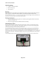
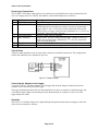
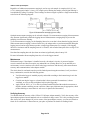
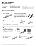
12-Bit 0-5 Volt Input Adapter (Part # S-VIA-CM14) The 12-Bit 0-5 Volt Input Adapter is used for measuring voltage levels and provides a trigger source voltage for powering external sensors and an open collector trigger. The input adapter has a plug-in modular connector that allows it to be added easily to a logger. Specification 12-Bit 0-5 Volt Input Adapter Measurement Range Accuracy 0 to 5 V ± 0.025 V (± 0.5% full scale) over full temperature range of -40°C to 75°C (-40°F to 167°F) ± 1.221 mV 1 MΩ Resolution Input Impedance Maximum Input Voltage Sensor Trigger: Open Collector Sensor Trigger: Source Operating Temperature Range Housing User Connection Dimensions Weight Number of Data Channels* Measurement Averaging Option Digital Filtering Bits per Sample Length of Network Cable* Part Number 30 V Maximum sink current: 115 mA On time: 12.7 ms ± 3% Voltage: 2.5 V ± 2.4%; maximum current: 1 mA On time: 12.7 ms ± 3% -40° to 75°C (-40° to 167°F) Plastic case; must be placed inside logger enclosure to protect from direct exposure to the weather Six-position screw terminal strip (16 - 30AWG); shielded cable recommended with outside diameter of 3.2 mm to 3.8 mm (0.125 in. to 0.150 in.) 4.5 x 4.8 x 1.6 cm (1.8 x 1.9 x 0.6 in.) 25 g (0.88 oz) 1 Yes Automatic digital filtering with 32 readings/sample in 2.4 ms 12 14 cm (5.5 in.) S-VIA-CM14 The CE Marking identifies this product as complying with all relevant directives in the European Union (EU). * A single logger can accommodate up to 15 data channels and up to 100 m (328 ft) of network cable (the digital communications portion of the input adapter and smart sensor cables), although available space in the enclosure may limit the number of sensors you can attach. © 2003–2013 Onset Computer Corporation. All rights reserved. Onset and HOBO are registered trademarks of Onset Computer Corporation. Part #: MAN-S-VIA Doc #: 7554-B Distributed by MicroDAQ.com, Ltd. www.MicroDAQ.com (603) 746-5524 12-Bit 0-5 Volt Input Adapter Inside this package 12-Bit 0-5 Volt Input Adapter Hook-and-loop tape Three cable ties Mounting Use the self-adhesive hook-and-loop tape included in the package to mount the input adapter inside the logger enclosure. To mount more than one adapter, use the back of the logger enclosure door. For the HOBO Micro Station, you can place the input adapter inside the logger enclosure and allow it to float freely. It is not necessary to use the hook-and-loop tape. Mounting Considerations If sensor cables are left on the ground, use a conduit to protect against animals, lawn mowers, exposure to chemicals, etc. Refer to the logger manual for additional details on mounting. Attaching Sensor Cables Insert the cable through the opening at the bottom of the logger enclosure as described in the logger manual. Be sure to provide “drip loops” underneath the logger to prevent water from trickling up the cable and into the logger. Pack the opening with duct seal. For the HOBO Micro Station, bring the cable through the logger’s sensor port. (See the HOBO Micro Station User’s Guide for details on removing the dome nut and stuffing gland from the sensor port.) Ensure that the cables to the sensor are the appropriate size for the stuffing gland (0.125-0.15 inches). Be sure to provide “drip loops” underneath the logger to prevent water from trickling up the cable and into the logger. Use the included cable tie to provide strain relief to the cable (or individual wires), as shown below. Figure 1: Cable strain relief Page 2 of 4 Distributed by MicroDAQ.com, Ltd. www.MicroDAQ.com (603) 746-5524 12-Bit 0-5 Volt Input Adapter Sensor Input Connections The 12-Bit 0-5 Volt Input Adapter utilizes a 6-position screw-terminal block for sensor connections with wire sizes ranging from 16 to 30AWG. Pin numbers, names and descriptions are as follows: Pin # 1 2 Pin Name GROUND TRIG. OPEN COLL. 3 4 VOLTAGE INPUT TRIG. SOURCE 5 6 NC SHIELD Description Ground. Used as a common connection. Trigger open collector (used to activate external sensors). Provides a switched ground for external power sources (connects to ground when trigger signal is “true”). Can also be used in conjunction with external pull-up resistor to trigger external circuitry. Maximum 30 V, 115 mA. See “Operation” below for timing diagrams. Provides voltage input for sampling. Trigger source. Provides voltage from the logger’s battery to power, or trigger, the external circuitry. Maximum 2.5 V, 1 mA. See “Operation” below for timing diagrams. No connection. Connects cable shield for noise suppression and circuit protection. Typical Setup A typical voltage transducer setup is shown below with power and shield connections. This configuration requires the transducer to be continuously powered. Figure 2: Transducer setup Connecting the Adapters to the Logger To use the 12-Bit 0-5 Volt Input Adapter, stop the logger and insert the adapter’s modular jack into an available sensor connection port on the logger. The logger automatically detects the new input adapter the next time you launch it. Launch the logger and verify that the input adapter is functioning correctly. Measurements are recorded in volts (V). See the logger manual for details. Operation The 12-Bit 1-5 Volt Input Adapter uses digital filtering and optional measurement averaging to reduce the effect of noise and improve accuracy. Page 3 of 4 Distributed by MicroDAQ.com, Ltd. www.MicroDAQ.com (603) 746-5524 12-Bit 0-5 Volt Input Adapter Regardless of whether measurement averaging is used or not, each sample is comprised of a 10.3 ms (± 3%) warmup period and a 2.4 ms (± 3%) sample period. During the sample period, digital filtering is accomplished by taking 32 readings. These readings are then averaged to produce a single measurement, as shown in the following diagram: Figure 3: Measurement averaging (not to scale) Optional measurement averaging can be selected at launch. Use measurement averaging if measurements may fluctuate significantly within the logging interval. Measurement averaging helps to prevent the sampling error known as aliasing. To use measurement averaging, set the Sampling Interval to a rate that is faster than the logging interval. When measurement averaging is selected in this way, the adapter takes several measurements during the logging interval and averages them to produce a single logged data point. For example, if the logging interval is 10 minutes and the sampling interval is 1 minute, each recorded data point is the average of 10 measurements. Note that fast sampling intervals (less than one minute) significantly reduce battery life. For more information about sampling intervals, refer to the logger manual. Maintenance With normal usage, if the adapter is installed correctly, the adapter’s circuitry is protected against excessive moisture and does not require any maintenance or cleaning. However, in an unusually wet environment, excessive moisture can collect in the logger enclosure and adversely affect measurement accuracy and communications in the adapter module. The circuit board is conformal coated to provide limited protection against moisture, but if you observe heavy condensation, consider the following options: Verify that the logger is installed properly and sealed according to the instructions given in the logger user manual. Consider moving the logger to a location that is better protected from moisture, is better ventilated, or receives some sunlight to help keep the logger dry. Apply WD-40, LPS 1, or 711 to the six-position terminal block and the modular connectors to displace moisture and help prevent corrosion. (Other spray lubricants may be appropriate; check product labeling to ensure that it is safe to use on plastics and electronics.) Verifying Accuracy You should check the accuracy of the 12-Bit 0-5 Volt Input Adapter annually. Verify the accuracy of the input adapter against a known standard, such as a calibrated voltage source. If it is not providing accurate data, it may have been damaged. If you are unsure of the input adapter accuracy, you can send it back to Onset for re-certification. Contact Onset or your place of purchase for details on sending it back. Page 4 of 4 Distributed by MicroDAQ.com, Ltd. www.MicroDAQ.com (603) 746-5524